
 Open Access Article
 This Open Access Article is licensed under a Creative Commons Attribution-Non Commercial 3.0 Unported Licence
Nanostructuring determines poisoning: tailoring CO adsorption on PtCu bimetallic nanoparticles†
Lorena
Vega‡
 ab,
Julia
Garcia-Cardona‡
a,
Francesc
Viñes
*ab,
Pere L.
Cabot
*a and
Konstantin M.
Neyman
abc
ab,
Julia
Garcia-Cardona‡
a,
Francesc
Viñes
*ab,
Pere L.
Cabot
*a and
Konstantin M.
Neyman
abc
aDepartament de Ciència de Materials i Química Física, Universitat de Barcelona, c/Martí i Franquès 1-11, 08028 Barcelona, Spain. E-mail: francesc.vines@ub.edu; p.cabot@ub.edu
bInstitut de Química Teòrica i Computacional (IQTCUB), Universitat de Barcelona, c/Martí i Franquès 1-11, 08028 Barcelona, Spain
cICREA (Institució Catalana de Recerca i Estudis Avançats), Pg. Lluís Companys 23, 08010 Barcelona, Spain
First published on 11th March 2022
Abstract
Here we show, combining CO stripping voltammograms on different PtCu nanoparticle (NP) low-temperature fuel cell electrocatalysts and density functional calculations, that surface chemical ordering and the presence of certain defects explain the CO tolerance vs. poisoning of such systems. The CO withdrawal for these duelling CO-slingers depends on whether they are well-shaped core@shell Cu@Pt NPs, more CO-tolerant, or having Cu-surrounded surface Pt atoms or adatoms/vacancies surface defects, less CO-tolerant. The latter sites are critical on nm-sized PtCu NPs, displaying stronger CO adsorption compared to pure Pt NPs. Avoiding such sites is key when designing less expensive and CO-poisoned Cu@Pt NP-based electrocatalysts.
1 Introduction
Fuel cells are regarded as a forefront, efficient way to transform chemical energy into electricity involving low pollutant emissions,1 highly appealing, e.g., to provide power for small residential areas, even when remote. Aside, fuel cells are attractive to the automotive sector and portable electronic devices, to mention a few applications of technological interest.2,3 In this context, proton exchange membrane fuel cells (PEMFCs) have arisen as one of the most promising technologies contributing to meeting the growing global energy demands while keeping sustainable zero carbon emissions, particularly thanks to their high energy density and efficiency, with demonstrated durability.4Platinum is the main electrocatalyst for PEMFCs, long regarded as the best material to carry out the hydrogen oxidation reaction (HOR) and the oxygen reduction reaction (ORR). However, Pt scarcity translates into prohibitive costs, plus it gets readily poisoned when the industrial grade hydrogen (H2) source contains carbon monoxide (CO) impurities,5 given the strong bond of CO to Pt surfaces.6 The CO tolerance can be improved, e.g., using PtRu alloy electrocatalysts, but at the expense of decreasing the fuel cell efficiency and yet introducing another expensive metal.7
An appealing way of decreasing the costs is to employ core@shell M@Pt nanoparticles (NPs), in which a more abundant and cheaper metal constitutes the NP core not directly participating in the catalytic process. In addition, the NP shaping aids at increasing the surface-to-mass ratio. Note that such solutions may imply a modulation of the Pt shell electronic structure by the core M metal,8 affecting the catalytic power, the CO affinity, and even the core@shell NP stability.9 Thus, the core@shell NPs composition, size, and shape are envisaged as controllable features to maximize the H2 activation while reducing the CO poisoning.
Along this line, diverse experiments have been performed with a plethora of cheaper sacrificial metal cores, M = Co, Ni, Fe, Sn, Mn, Zn, or Pb.10–16 Among them, the Cu@Pt formulation has attracted great attention10,17,18 given the availability of Cu, a common catalyst, e.g. for the reverse water gas shift reaction,19 and used as an electrocatalyst for the carbon dioxide reduction reaction.20 There exists a number of methodologies to prepare Cu@Pt NPs supported on porous carbon, including direct current,21 and chemical reduction of Cu ions by sodium borohydride or formaldehyde,22–25 generally followed by galvanic exchange with Pt. The galvanic exchange has been previously used as a simple and cost-effective method to synthesize catalysts for different important electrochemical applications.26 Thus, as some examples of pioneering works, Pt submonolayers on Ru NPs,27 Pt layers on Au surfaces,28,29 Pt monolayers on core–shell NPs (by displacing Cu monolayers),30 and Pt shells covering Cu, Ni, and Co deposits on glassy carbon substrates31 were prepared in this form.
It is known that Cu@Pt NPs are excellent catalysts for NOx reduction.32 Their thermodynamic stability, rationalized by density functional theory (DFT) simulations on NP models,33 revealed a significant cohesion and commensurability of Cu and Pt phases. The improved catalytic activity was assigned to a Cu → Pt electron transfer and a lowering of the Pt d-band centre. This mechanism was invoked as well to explain the weaker CO binding on Cu@Pt systems using slab-model DFT simulations of Pt monolayers on Cu support.34 Note that on extended systems the effect is maintained, although less expressed, even in case of a surface Pt single atom alloy (SAA) as follows from the observations of improved CO poisoning tolerance of PtCu SAA.35
However, not all that glitters is gold, and the manufacturing of Cu@Pt NPs is not exempt from adverse effects in terms of CO poisoning, which may be enhanced by particular NP size, shape, or synthesis procedures. We show this here by decreasing the size limits to circa 1.5 nm for Cu@Pt particles obtained by galvanic exchange and Cu selective oxidation, thus prompting the possibility of having a diversity of abundant defects at the NP surface. The CO stripping voltammograms on a series of synthesized and commercially available Cu@Pt NPs with different particle sizes and Pt:Cu ratios reveal that the CO adsorption is, in general terms, weakened compared to pure Pt NPs, but, in the smallest size limit, it may be remarkably strengthened. An atomistic insight gained by DFT simulations on Cu@Pt NP models reveals that certain surface defects, including Cu-surrounded Pt atoms, Pt adatoms, and Pt vacancies, may decrease the tolerance towards CO poisoning.
2 Experimental details
2.1 PtCu bimetallic nanoparticles synthesis
The PtCu catalysts studied in this work were synthesized by different procedures. They all consisted in a two-step synthesis where carbon-supported Cu NPs (Cu/C) were firstly obtained by different deposition methods. Later, once the Cu/C was formed, a partial galvanic replacement took place when the powder was suspended in a 5 mM H2PtCl6 + 0.1 M HClO4 solution with vigorous stirring for 45 min, proceeded according to the following reaction:| 2Cu + PtCl62− → 2Cu2+ + Pt + 6Cl−. | (1) |
The resulting carbon-supported Cu@Pt core@shell NPs were separated, cleaned, and dried. Carbon XC72 from Cabot Corp. was used as the support in all cases. All the solutions were prepared from Milli-Q water (Merck) and the analytical-grade reagents from Merck GmbH (NaBH4, H2PtCl6, Na2-EDTA, n-heptane, Brij-30, acetone, ethanol) and Panreac Applichem GmbH (CuSO4·5H2O, formaldehyde, NaOH, polyvinylpyrrolidone).
The electroless deposition to obtain Cu NPs was performed in basic aqueous media, using formaldehyde or NaBH4 as reducing agents, and in water in oil microemulsion, using NaBH4. Synthesis 1, S1, consists in the preparation of the Cu/C catalyst precursor following the work of Georgieva et al.23 The carbon powder was dispersed in 100 mL of a solution containing 10 mM CuSO4·5H2O as the Cu precursor, 30 mL L−1 CH2O as the reducing agent, 50 mM Na2-EDTA as the complexing agent, and as the surfactant 0.0005 mM polyvinylpyrrolidone (PVP). The pH was raised up to 12.5–13.0 with NaOH and then the suspension was kept at 45 °C in a water bath under stirring for 30 min. The suspended solid was centrifuged at 9500 rpm for 15 min and then re-suspended in ultrapure ethanol and centrifuged again several times to remove the surfactant. The Cu/C NPs were left to dry under vacuum overnight. Synthesis 2, S2, was performed from a sonicated suspension containing given amounts of CuSO4·5H2O and the carbon support in 1.0 M NaOH. Then, NaBH4 was slowly added during 15 min for the copper deposition, the sonication continued for 30 min more and then, the suspension was filtered.25 In Synthesis 3, S3, the catalysts were prepared by a water-in-oil method,36 which consists in a microemulsion containing n-heptane, Brij-30 as the surfactant, and an aqueous solution of CuSO4, with a water-to-surfactant molar ratio of 7. An excess of NaBH4 was added to form Cu NPs, further sonicating the microemulsion for 2 h. Finally, 21 mg of the carbon support were added to the microemulsion, which was further kept stirred for 1 h and then, the phase separation was produced by acetone addition. Once the organic phase was separated from aqueous phase and cleaned, the resulting powder was filtered.
2.2 CO stripping experiments
The electrochemical experiments were done in a three-electrode electrochemical cell using an Ag|AgCl|KClsat reference electrode, a Pt stick auxiliary electrode, and a 5 mm-diameter glassy carbon electrode (GCE) as the working one (all from Metrohm). The GCE was polished to mirror finish as described elsewhere.25 The electrolyte was 0.5 M H2SO4 (Merck, analytical grade) and the experiments were performed using an Ecochemie Autolab PGSTAT100 commanded by the Autolab Nova 2.1.4 software. The GCE was coated with 20 μL of the catalyst ink, prepared by sonicating 1 mg of the catalyst powder dispersed in 0.5 cm3 of a water![[thin space (1/6-em)]](https://www.rsc.org/images/entities/char_2009.gif) :isopropanol (analytical grade, Panreac) mixture (1:1 in volume), and left to dry at room temperature. Despite not using the Nafion binder, the particulate films were found to be stable during the present measurements. Prior to the CO stripping experiments, the ink-modified electrode was cleaned by repetitive cycling between −0.2 and 0.8 V at 100, 50 and 20 mV s−1 up to a steady profile. It is worth mentioning that this is a normal procedure to obtain clean Pt surfaces also for PtCu NPs (activation process). To this respect, it is important to note that the steady profiles were rapidly obtained, with no extra peaks apart from those typical of pure Pt, and that the difference between the first and the steady curves was only a slight increase in the peak currents (also observed for Pt/C). Therefore, the surface restructuration, being possible, should be minimum. To obtain the CO stripping curves, CO gas (99.9% Linde) was bubbled through the 0.5 M H2SO4 solution for 15 min keeping the electrode potential at −0.1 V. Dissolved CO was removed by N2 bubbling (99.9995% Linde) through the solution for 30 min and then, the monolayer of CO adsorbed on the surface was oxidized by cyclic voltammetry (CV) between −0.2 and 1.0 V at 20 mV s−1 without stirring. The experimental results were compared with those obtained using commercial 20 wt% Pt/C and 20 wt% PtCu/C (1:1 at. ratio), both from Premetek, after preparing the corresponding working electrodes in the same way as indicated above.
:isopropanol (analytical grade, Panreac) mixture (1:1 in volume), and left to dry at room temperature. Despite not using the Nafion binder, the particulate films were found to be stable during the present measurements. Prior to the CO stripping experiments, the ink-modified electrode was cleaned by repetitive cycling between −0.2 and 0.8 V at 100, 50 and 20 mV s−1 up to a steady profile. It is worth mentioning that this is a normal procedure to obtain clean Pt surfaces also for PtCu NPs (activation process). To this respect, it is important to note that the steady profiles were rapidly obtained, with no extra peaks apart from those typical of pure Pt, and that the difference between the first and the steady curves was only a slight increase in the peak currents (also observed for Pt/C). Therefore, the surface restructuration, being possible, should be minimum. To obtain the CO stripping curves, CO gas (99.9% Linde) was bubbled through the 0.5 M H2SO4 solution for 15 min keeping the electrode potential at −0.1 V. Dissolved CO was removed by N2 bubbling (99.9995% Linde) through the solution for 30 min and then, the monolayer of CO adsorbed on the surface was oxidized by cyclic voltammetry (CV) between −0.2 and 1.0 V at 20 mV s−1 without stirring. The experimental results were compared with those obtained using commercial 20 wt% Pt/C and 20 wt% PtCu/C (1:1 at. ratio), both from Premetek, after preparing the corresponding working electrodes in the same way as indicated above.
2.3 NP size, morphology, and composition characterization
Transmission electron microscopy (TEM) by means of a 200 kV JEOL JEM 2100 microscope was used for the sample observation. The X-ray diffraction (XRD) analyses were performed sandwiching the powders between 3.6 μm-thick polyester films using a PANanalytical XPert PRO MPD θ/θ powder diffractometer (Cu anode, 45 kV, 40 mA). The measurements were conducted with a Cu Kα-filtered radiation ( = 1.5418 Å), 2θ step size of 0.026° and 200 s per step of measuring time. The TEM observation of the specimens studied showed the presence of small nanoparticles, dispersed on the supporting carbon. Representative examples are shown in Fig. 1a and b for S1 and commercial PtCu/C, respectively. NPs about 1–2 nm in diameter can be observed in the picture of the former and of about 3–4 nm in that of the latter, also presenting, as expected, some size distribution.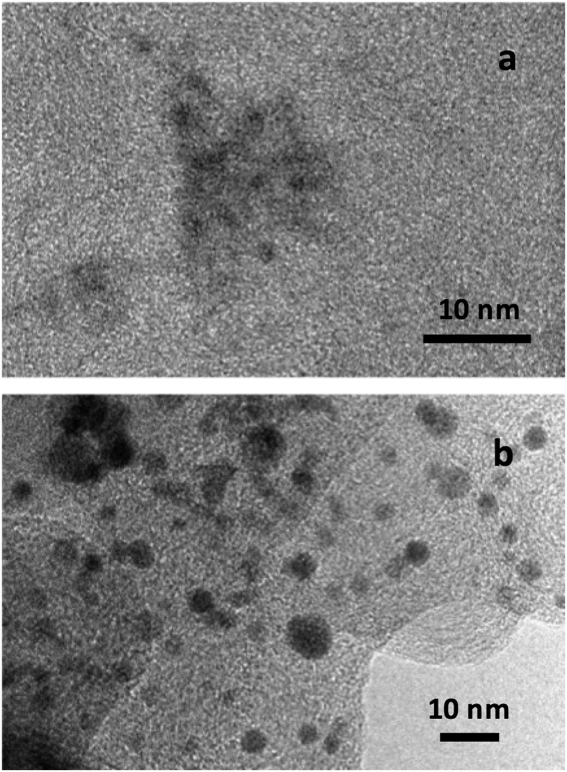 | ||
| Fig. 1 Representative TEM pictures of the PtCu catalysts studied. (a) S1 and (b) commercial PtCu/C. | ||
As shown in this Fig. 1, the NPs were rather spherical, and some aggregation could also be observed. It is then difficult to identify whether all the dark spots are single crystals (crystallites). Different analytical techniques such as XRD, X-ray photoelectron spectroscopy (XPS), energy-dispersive spectroscopy (EDS) and inductively coupled plasma have been used to analyse the composition of the samples.10,17,18,22,24,25 It should be noted, however, that the analytical results obtained from all these techniques would coincide only when the NPs were composed of the zero-valent elements and were completely crystalline and homogeneous. It was shown by XPS that Pt and Cu oxidized states appeared for PtCu NPs supported on different carbons, which could not be integrated into the crystallites.25,52 In addition, the Pt(0):Cu(0) at% ratios obtained by the XPS analyses performed with different sputtering time approached those of XRD. It was also shown that the overall composition given by EDS significantly differed from the composition of the crystallites ascertained by XRD and XPS, which was then explained by the presence of the significant amounts of the identified Pt and Cu oxidized species. Considering that the metallic PtCu solid solution—Pt(0):Cu(0)—is the main structure involved in CO oxidation, since the oxidized species are not expected to work for this reaction, and that XRD allows identifying such Pt(0):Cu(0) single crystals, the studied catalysts were accordingly analyzed by means of the XRD technique.
The XRD patterns of the synthesized catalysts are shown in Fig. 2, where they are compared to commercial Pt/C and PtCu/C samples. The focus on the 35 to 55° region allows one comparing the peaks to the expected signals for Pt and Cu(111) and (200) surfaces, and thus confirming the Pt phase of Pt/C reference, as well as Pt-like and Cu-like phases of different composition on commercial PtCu/C and samples S1 to S3. It is worth mentioning that the XRD results show the mean composition of the crystallites through the peak displacements from those corresponding to the pure metals. The peak diffraction angles of the PtCu NPs shown in Table 1 are between those of pure Pt and pure Cu, but closer to the former, thus indicating that Pt is dominant in the crystallites.
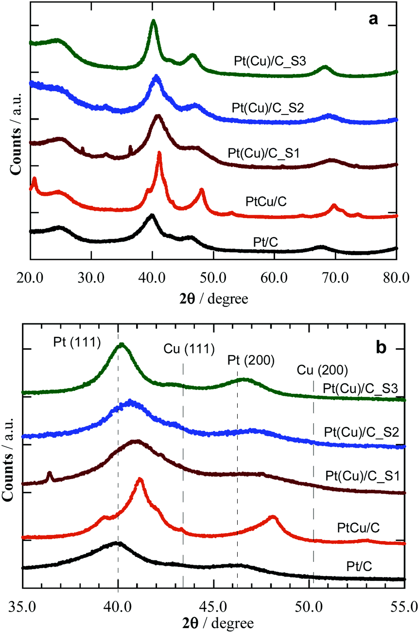 | ||
| Fig. 2 XRD patterns of the studied Pt and PtCu catalysts. (a) Extended XRD diffractograms and (b) magnification of the peaks with higher intensity. The diffraction angles of pure Pt and Cu crystallites have been marked for comparison. | ||
| Catalyst | Crystallite size/nm | Pt:Cu ratio/at% |
Lattice parameter (a)/nm |
|---|---|---|---|
| PtCu/C_S1 | 1.5 | 64:36 |
0.3814 |
| PtCu/C_S2 | 2.0 | 73:27 |
0.3838 |
| PtCu/C_S3 | 3.5 | 91:9 |
0.3885 |
| PtCu/C | 3.4 | 57:43 |
0.3805 |
| Pt/C | 2.6 | 100:0 |
0.3911 |
Table 1 summarizes the XRD results, i.e. the average NP size (from Scherrer's equation) and the Pt:Cu ratios (Vegard's law). Note that commercial PtCu/C and Pt/C samples have mean NP sizes of 3.4 and 2.6 nm, the former with a Pt:Cu at% ratio of 57:43. Samples S1 to S3 featured increasing size, from 1.5 to 3.5 nm, and decreasing of the Cu content, from Pt:Cu 64:36 in S1 to 91:9 for S3, in line with a Cu@Pt core@shell structure, since the surface Cu atoms were removed and replaced by Pt atoms during the galvanic exchange.25 The samples offer cases of similar size, around 2 (S1, S2, and Pt reference) or 3.5 (S3 and PtCu) nm, with variable composition, and also cases with similar composition and different size, e.g.S3 and Pt reference, or S1 and PtCu, enabling a discussion of size and composition effects.
Aside, the lattice parameters, a, determined from the XRD diffractograms, go along with the Cu content, i.e. the larger the Cu content, the smaller is a, thus resulting in a concomitant lattice strain increase while reducing the NP size.33Table 1 shows that an increase in the Cu content in S1–S3 is paired with a NP size decrease. This is an expected result when the number of the overall atoms in the NPs are the same. However, this is difficult to control in the synthesis, also because of the distribution of NP sizes and compositions achieved, which makes their analysis only viable through mean values. The final NPs were the result of the galvanic replacement of Cu by Pt, which means that the initial Cu NPs were partially destroyed together with an alloy formation, with the final composition and size as indicated in Table 1. Therefore, the NP size has to be mainly related to the different synthesis methods, which also conditioned the NPs composition. Note the different NP composition of commercial PtCu/C, resulting from another synthesis procedure, involving the simultaneous chemical reduction of Pt and Cu precursors with the alloy formation to a given NP size.
3 Methods and models
3.1 Computational details
The present DFT calculations were carried out using the plane-wave based Vienna ab initio simulation package (VASP) code.37,38 The Perdew–Burke–Ernzerhof (PBE)39 exchange–correlation functional was used in the description of the valence electrons, combined with the projector augmented wave (PAW) representation of core electrons.40,41 Given the strong adsorption of CO on Pt, the inclusion of dispersive forces just slightly increases the adsorption strength, as shown on Pt(111), by ∼0.3 eV.42 Thus, the poisoning by CO due to its strong chemical bonding to Pt is reasonably well accounted at the PBE level. Metal NPs were modeled within a 2.5 × 2.5 × 2.5 nm large periodically repeated cells with at least 0.75 nm separation between adjacent particles, with negligibly weak interactions of metal NPs at such distances.43 Only the Γ Brillouin zone k-point was sampled for the single NPs. The kinetic energy cut-off for the plane-waves basis set was set to 415 eV, a value large enough to acquire adsorption energies converged within chemical accuracy, i.e. below ∼0.04 eV. For the electron density calculation, a cut-off value of 450 eV provided properly converged Bader charges. One-electron levels were smeared by 0.2 eV through a Gaussian function, yet finally the converged energies were extrapolated to zero smearing. All atoms were fully relaxed accomplishing a maximum forces criterion of 0.02 eV Å−1. Charges were evaluated through a Bader atoms-in-molecules analysis, and charge density difference (CDD) plots gained as the electron density difference of the system containing the NP with the adsorbed CO, and the electron densities of the isolated NP and CO at fixed geometry of the adsorption system.443.2 Employed nanoparticles models
The PtCu NPs models were constructed mimicking the experimental ca. 60 at% Pt and 40 at% Cu composition of sample S1, while using as template 201-atoms truncated octahedrons, following the Wulff construction shape minimizing the NP overall surface tension,45 which resulted in an average NPs diameter of ∼1.5 nm, explicitly meeting the sample S1 NPs size, although the models are suited to simulate the CO adsorption on larger NPs, such as those of samples S2 and S3, being the CO adsorption of local character, vide infra, while such NPs being within the so-called scalable regime,33,43 where adsorption results are converged with the NP model size. The model NPs already feature a metallic band structure, at variance with the discrete energy levels featured by smaller metal clusters.33 The models created to simulate different present active sites in experiments are as follows: (i) an immaculate (regular) Cu@Pt core@shell NP, Cu79@Pt122—model 3—which obeys the topological stability preference;46 (ii) a Cu78Pt@Pt121Cu model derived from model 3 exchanging one surface Pt atom with one core Cu atom—model 5—; (iii) NPs with single surface Pt atoms surrounded by surface and subsurface Cu neighbors—model 6—; (iv) NPs with single surface Pt atoms surrounded by surface Cu neighbors—model 7—, (v) models derived from model 7 removing surface Cu atoms and optimizing the resulting structure—model 8—; and (vi) models with surface defects created on the immaculate Cu79@Pt122 model—adatom and vacancy models—.Except for the Cu79@Pt122 NP, different models had to be built to duly represent the variety of surface defects. Notice that models 5–7 represent situations with a marginal surface Cu content, which cannot be completely ruled out neither from the synthesis procedure, nor the XRD analysis, nor the Cu surface segregation under working conditions. However, model 8 and adatoms and vacancies mimic situations where such surface Cu has been selectively oxidized and removed during the voltammogram cycles. Finally, apart from the just mentioned PtCu model NPs, the following reference systems were also calculated: Pristine Pt201—model 1—and Cu201 NPs—model 2—, inverse Pt79@Cu122—model 4—, and pure Pt201 NPs with generated surface defects, see Fig. 3.
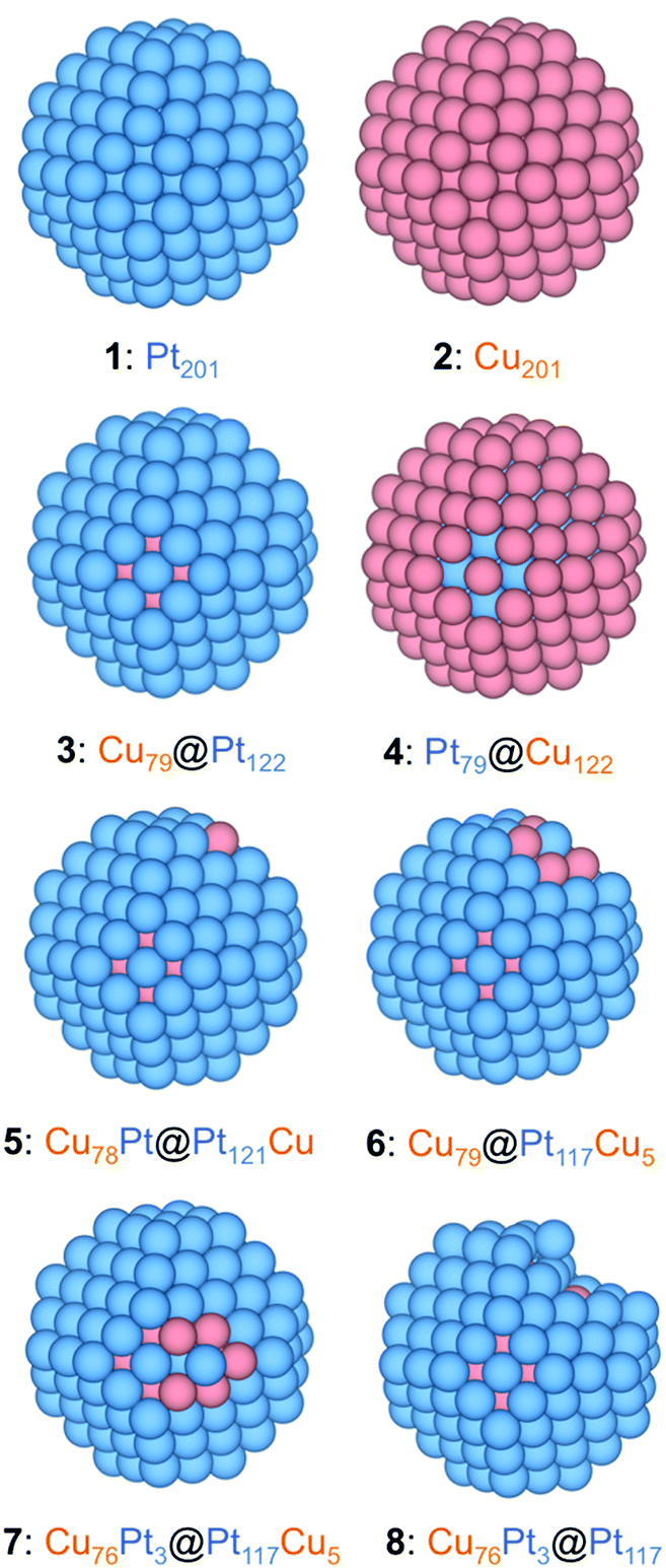 | ||
| Fig. 3 Eagle-eye views of the different employed NP models: 1: pure Pt201; 2: pure Cu201; 3: Cu79@Pt122—perfect Cu-core@Pt-shell; 4: Pt79@Cu122—perfect Pt-core@Cu-shell; 5: Cu78Pt@Pt121Cu—an example of exchanging a core Cu atom with a surface Pt atom (a corner site in the example); 6: Cu79@Pt117Cu5—with a surface Pt atom (a corner site in the example) surrounded by Cu atoms; 7: Cu76Pt3@Pt117Cu5—as in 6, but with the Pt atom surrounded by 5 surface Cu atoms and one subsurface Pt atom; 8: Cu76Pt3@Pt117—resulted from 7 by removing 5 surface Cu atoms and subsequent geometry optimization. Pt and Cu atoms are shown as blue and brown spheres. | ||
3.3 CO adsorption assessment
CO molecule adsorption was systematically studied on the aforementioned NP models. Numerous positions were considered, see Fig. S1 of the ESI,† including top, bridge, and face-centred cubic (fcc) hollows, regarded to be more stable than hexagonal close packed (hcp) hollows.33 In addition, CO adsorption was investigated on the surface vacancy defected models with one, three, or seven atoms missing on the (001) and (111) facets. CO adsorption energy, Eads, was calculated from the energies of the optimized CO molecule, ECO, clean NP, ENP, CO adsorbed on the NP model, ECO/NP, as follows:| Eads = ECO/NP − ENP − ECO. | (2) |
Within this definition, the more negative the Eads is, the stronger is the CO adsorption. Aside from testing hcp from fcc sites, our calculations revealed a clear trend towards the perpendicular CO adsorption via its C atom, even when starting from a parallel CO adsorption mode with both C and O atoms interacting with the NP. Aside, a very weak O-connected CO perpendicular adsorption is found, with Eads of at most of −0.05 eV, see Table S1 of the ESI.† Thus, the latter adsorption mode has been discarded in the oncoming discussion, considering only the much stronger C-connected CO perpendicular adsorption, see Table 2.
| Model/Site | A | B | C | D | E | F |
|---|---|---|---|---|---|---|
| 1 | −2.08 | −2.01 | −1.77 | −1.52 | −1.68 | −2.05 |
| 2 | −0.98 | −0.90 | −0.79 | −0.60 | −0.62 | −0.86 |
| 3 | −1.74 | −1.54 | −1.40 | −0.61 | −1.03 | −1.65 |
| 4 | −1.25 | −1.15 | −1.09 | −0.97 | −0.97 | −1.13 |
| 5 | −0.95 | −0.82 | −0.60 | −0.35 | −0.45 | −0.88 |
| 6 | −1.88 | −1.83 | −1.81 | −1.21 | −1.44 | −1.76 |
| 7 | −2.24 | −2.27 | −2.22 | −1.67 | −1.94 | −2.07 |
| 8 | −2.07 | −2.21 | −2.61 | −2.29 | −1.58 | −1.81 |
4 Results and discussion
4.1 CO stripping voltammograms on reference Pt and PtCu bimetallic nanoparticles
The CO stripping studies have been carried out for three PtCu bimetallic NP systems synthesized on a carbonaceous support, named S1, S2, and S3, and compared with Pt/C and PtCu/C commercial catalysts, see Fig. 4. The general shape of these curves is typical for Pt.47 The main peak appears in these curves during the anodic sweep, in the potential range 0.5–0.8 V, which corresponds to the oxidation of adsorbed CO. This peak is preceded by a suppression of H adsorption/desorption due to CO adsorption at Pt active sites. After the CO stripping, Pt is oxidized to surface PtO, which is reduced again to Pt in the cathodic sweep, leading to the peak located at about 0.6 V. Afterwards, the hydrogen adsorption profile, also typical for Pt, appears in the potential range from 0.1 to −0.2 V. It is also apparent that the carbon powder substrates show high capacitive currents in that region, thus obscuring the H adsorption picture.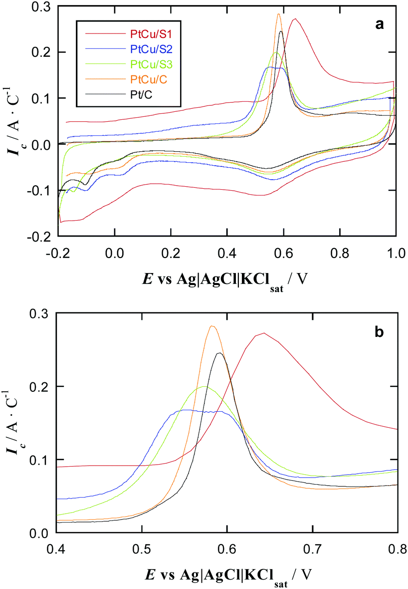 | ||
| Fig. 4 (a) CO stripping curves of PtCu and reference Pt samples in deaerated 0.5 mol dm−3 H2SO4 at a scan rate of 20 mV s−1. (b) Magnification of the curves to better visualise the onset potential for CO oxidation. | ||
Note that the currents have been referred to the CO stripping charge of each specimen. When normalizing in this form, the Pt loading is not relevant, since the stripping charges are proportional to the number of active sites, and then, the onset potentials for CO oxidation, which indicate the relative catalytic activities, can be easily compared. Importantly, no Cu oxidation is perceived in the CV curves of Fig. 4. In the case that some free Cu remained on the surface, it should be oxidized at 0.0–0.2 V potentials48 and no peaks can be observed in this potential region.
In the case of the S1, S2, and S3 samples, this can happen because (i) during the galvanic replacement, Pt atoms remove the surface Cu atoms of the previously deposited Cu NPs and (ii) after the repetitive cycling to reach the steady profile, the possible remaining surface Cu atoms are removed. NPs of the commercial PtCu/C catalyst should also undergo a surface Pt enrichment according to the point (ii). However, it is important to note that no extra peaks apart from those typical of pure Pt appeared in the cleaning protocol (repetitive cyclic voltammograms), and, therefore, any Cu oxidation peak was not detected in any case, including the first voltammogram. This points out to a minimum Cu surface removal by the Pt shell protection of the underlying Cu, the CO stripping voltammograms showing the effect of Cu on Pt through shifting the onset of the CO oxidation potential. Besides, the size of the NPs studied in this paper was too small to detect Pt and Cu concentration gradients along the NP diameter (line profile) by energy-dispersive X-ray spectroscopy (EDS) because of insufficient spatial resolution of the technique.25,49–52 For small PtCu NPs (2–5 nm), obtained also by galvanic displacement of Cu by Pt on different carbon supports, X-ray photoelectron spectroscopy (XPS) analyses with different Ar+ sputtering times were performed.25,49–52 Interestingly, the XPS results showed that the Pt(0):Cu(0) ratio decreased when increasing the sputtering time, thus strongly indicating a Pt surface enrichment. Thus, the NPs can be described as having core@shell structures with a PtCu alloy core and a shell mainly composed of Pt atoms.
The profiles of the cyclic voltammograms in Fig. 4 are then the same as that of Pt/C, although with different potential shifts of the CO stripping peaks. The onset potential of these peaks indicates the strength of CO adsorption, being smaller as the onset potential is shifted in the negative direction. According to literature, many PtCu samples feature more negative onset potential for CO oxidation than pure Pt, seen e.g. in Cu@Pt core@shell NPs produced by electrochemical reduction of Cu followed by a partial galvanic replacement with Pt,21 NPs with a Cu–core to Pt–shell gradient structure,53 Pt NPs with a small content of dissolved Cu,54 even PtCu alloy NPs prepared using a reducing agent in basic media followed by a partial galvanic replacement with Pt.25 This is indeed observed in the CO stripping plots in Fig. 4 for commercial PtCu, PtCu_S2, and PtCu_S3 samples, revealing a weaker CO adsorption when compared to commercial Pt/C, and so, such samples duly accomplish the sought mission of performing similarly or even better than reference Pt/C, but with a lower Pt mass content.
The adsorbed OH necessary to generate CO2 (and water) during the oxidation process appears to play a minor role, a point quantified by DFT calculations. The calculated hydroxyl adsorption energy below −0.5 eV on pure Pt NPs54 suggests its easy displacement by CO molecules adsorbed at least 1 eV stronger; vide infra. Regarding the deviations with respect to pure Pt, commercial PtCu/C is the closest to Pt/C, with a peak potential shift of merely −10 mV, even when a Pt:Cu ratio is close to 60:40, see Table 1. The PtCu_S3 shows a peak shift of circa −50 mV; its similar size to commercial PtCu/C implies that the extra shift comes from the Pt:Cu composition of ca. 90:10, indicating that some effect is achieved at small contents of Cu, as observed for PtCu NPs with decreasing Cu content,55 even in solid solution limits containing just ca. 1 at% Cu.54 The PtCu_S2 sample has a particle size close to that of Pt/C, but with a ∼70:30 Pt:Cu ratio, also revealing a weaker CO adsorption.
Note that in this latter sample, a broad band appears in which one can discern two features at 0.54 and 0.58 V, which could be well related to well-faceted (111) and (100) Pt domains reported in the literature.56 Another possibility could be the coexistence of different orientations of the CO adsorbed molecule (horizontal and vertical), with different Pt-CO binding energies. However, the vertical orientation is normally considered due to the strong adsorption of CO on Pt. Related to this point, it is worth noting that the H desorption (the same as adsorption) charges in other PtCu/C alloys explored by us were half of the CO stripping charges,25 thus suggesting only one H atom (one electron for desorption) and only one CO molecule (two electrons for stripping) per Pt active atom and indicating the vertical adsorption of CO on the latter.
The most striking feature is that PtCu_S1 sample with Pt:Cu ratio 60:40 and 1.5 nm large particles features a CO oxidation peak shifted by ∼50 mV to more positive potentials compared to Pt/C sample, indicating a stronger CO poisoning of PtCu_S1. To the best of our knowledge, this is the first observation of CO poisoning enhancement for nanostructured PtCu samples. This is in strong contrast with the results obtained for commercial PtCu/C sample featuring not very different Pt:Cu composition, but significantly different NP size (3.4 nm). Note, however, that the negative onset potential shift for CO oxidation for commercial PtCu/C is smaller than those for PtCu_S2 and PtCu_S3 samples, thus suggesting that decreasing the amount of Cu in the PtCu alloy can facilitate the CO removal. However, probably there is not only a mere size effect. The synthesized NPs are the result of a galvanic exchange of Cu by Pt. If the initially deposited Cu NPs have significantly different sizes and surface structures in the applied preparation protocols the galvanic exchange may lead to PtCu NPs varying both sizes and surface defectiveness.
Since CO adsorption is a surface phenomenon, it is expected to strongly depend on the surface structure, being sensitive to the surface defects presence. To the best of the authors’ knowledge, it is, a priori, not yet possible to observe from experimental surface analyses the existence of surface defects in an about monolayer shell thickness. Indeed, the computational calculations performed for a wide set of possible models bridges this gap identifying defective and non-defective surface positions with different CO adsorption energies. We started with the simplest models, having in mind the complexity of the experimental NPs (and also of the calculations), with a complete coverage of the surface Pt sites by CO molecules, the solvent and electrolyte, and the carbon support.
4.2 Computational CO adsorptive landscapes on Pt and PtCu nanoparticles
In order to explain the aforementioned experimental findings, a systematic DFT study of the CO adsorption on realistic NP models has been carried out. Truncated octahedron shapes have been considered, in line to the equilibrium Wulff shape minimizing the NP surface tension.45 The basic NPs contain 201 atoms, corresponding to ∼1.5 nm size, comparable to the particles size in the PtCu_S1 sample. Pure Pt201 was used as a reference, and an immaculate Cu79@Pt122 core@shell NP with ∼40 at% Cu and ∼60 at% Pt has been studied, which may serve as explicit models the experimentally synthesized PtCu_S1 NPs, but are suited models for local adsorption simulations of larger NPs. Other references, such as pure Cu201 and an inverse Pt79@Cu122 NP, have been studied as well, vide supra. Pt adatoms on Pt201 and Cu79@Pt122 template NPs were inspected, as an ultimate expression of Pt low-coordination. Also, surface Pt vacancies were generated, mimicking situations in which surface Cu atoms have been selectively oxidized (removed). Furthermore, partially surface oxidized models, still containing Cu surface atoms, were investigated, e.g. exchanging core Cu and surface Pt exchange positions—Cu78Pt@Pt121Cu—, in line with previous studies suggesting that such surface Cu atoms could be beneficial for the CO oxidation, serving as vicinal OH adsorbing centres.54 Finally, we explored models with a surface Pt atom surrounded by Cu neighbors, see Fig. 3, since such structures have been appointed to bind CO stronger than Pt(111) surfaces, where the CO adsorption may favor the surface segregation of the subsurface Cu and increase the stability of surface alloys.57A thorough DFT study on all the plethora of adsorption sites and CO connection ways was carried out employing the above-mentioned NP models. Notice that the goal here is to find particular surface sites or structures that, because of their nature, favor or disfavor the CO bond strength, which is regarded as the key factor determining the CO bias in the experimental CO stripping curves. However, one should refrain from direct comparing the adsorption energies changes with the observed peak shifts, as the latter are also affected by factors other than the specific NP surface structure, e.g. coverage, solvation, and presence of electrolytes, to name a few.58 In addition, the samples feature a distribution of sizes and compositions, with a diversity of active sites. Thus, the aim is to find particular surface active sites responsible of the weakening or strengthening of the CO bond.
With that in mind, let us focus on the Eads. Not unexpectedly, DFT results show stable M–CO adsorption through C atom. Note that horizontal CO adsorption was also systematically tested, although in all cases the molecule raised to adopt a minimum with a vertical configuration, in line with experiments.25 The top positions were found to be the most preferred, and even though bridge and hollow positions feature CO adsorption minima, the CO tends to displace from many of them upon relaxation, decreasing its coordination, i.e. hollow → bridge and bridge → top, see Tables S2 and S3 of the ESI.† Thus, for a due comparison, only top adsorption sites are discussed in the following, see Table 2, present on all of the employed PtCu NP models and the Cu201 and Pt201 references.
Overall results on pure Cu and Pt@Cu NPs, as well as on isolated surface Cu atoms—Cu78Pt@Pt121Cu NP model—reveal weaker CO adsorption compared to Pt201, with Eads ranging from −0.35 eV—on Cu78Pt@Pt121Cu—to −1.25 eV—on Pt@Cu NP—, in line with data from Pt146Cu NP models,54 and clearly smaller in magnitude than on the corresponding sites of Pt201 NP, from −1.52 to −2.09 eV. As far as Cu@Pt NPs are concerned, the presence of surface Cu atoms would not prevent CO occupying exposed more strongly adsorbing surface Pt sites. So, surface Cu atoms would only lower the number of available Pt surface active sites per NP. Thus, only weaker CO bonding would be observed on pure Cu or Pt@Cu NPs. However, the Cu phase is not a viable substitute to the Pt phase in PEMFCs, plus the Pt@Cu NPs feature instability issues.32,33 If any, as aforementioned, such surface Cu atoms could be beneficial for a somewhat stronger OH adsorption, which could tune the CO oxidation performance towards CO2.54
Focusing on the CO adsorption on surface Pt atoms, a comparison is made between reference Pt201 NP, pristine Cu79@Pt122, and other Cu@Pt models where a Pt surface atom is fully surrounded by Cu atoms—having both surface and subsurface Cu neighbors—or superficially surrounded—having only surface Cu neighbors—. In the latter case, models were relaxed and analyzed, in which the surface Cu atoms were removed, mimicking the aforementioned Cu selective oxidation used to prepare the PtCu S1–S3 samples.25Fig. 5 shows the difference of CO adsorption energy, ΔEads, for these four models with respect to the Pt201 NP reference and reveals that the perfect Cu@Pt NP consistently features CO adsorption by 0.35 to 0.91 eV weaker, in line with the potential reductions shown in Fig. 3, and as a result of Cu → Pt charge transfer and lowering of the d-band centre.33
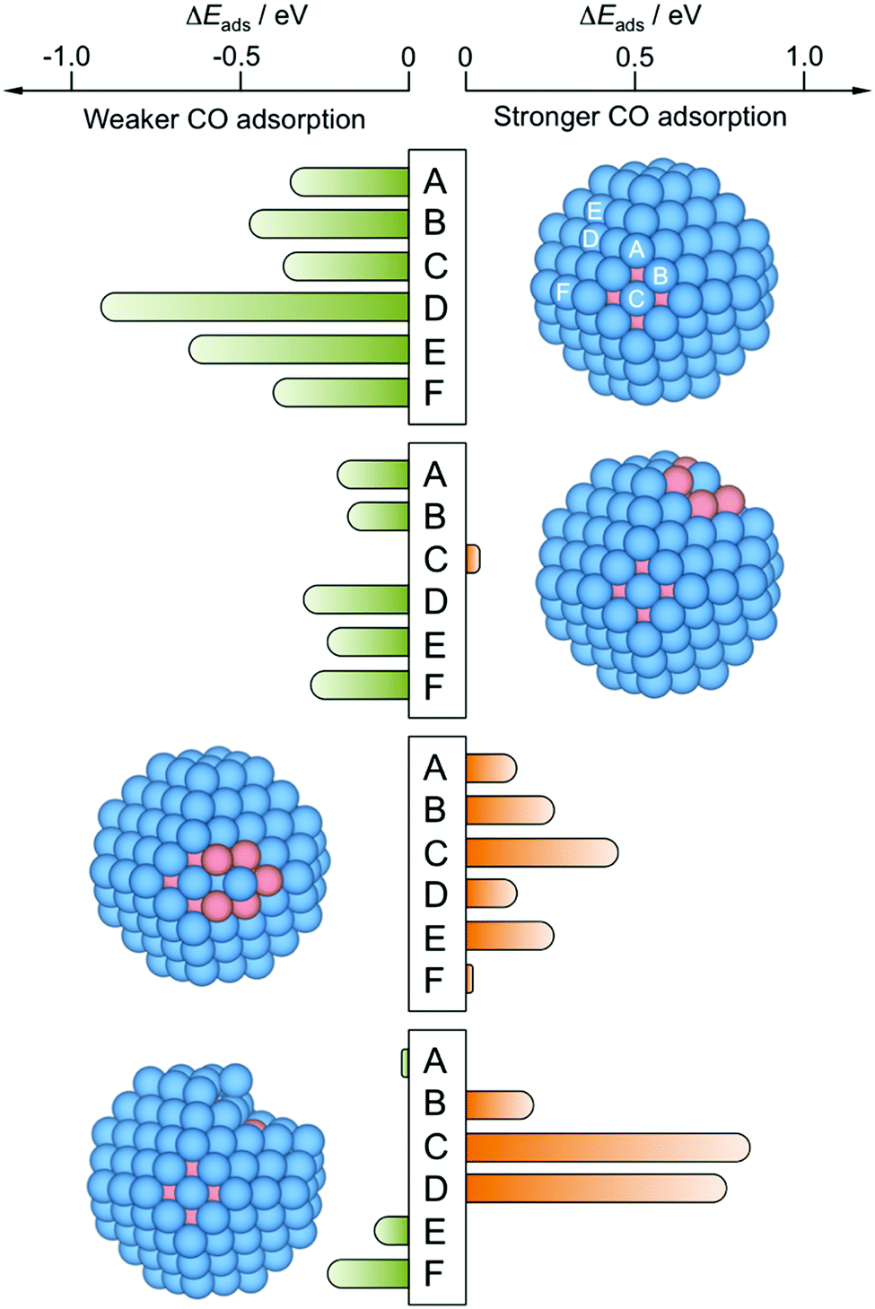 | ||
| Fig. 5 Differences in CO adsorption energies, ΔEads, on PtCu NPs with respect to reference Pt201 NP, calculated for all topologically different top sites, see Fig. S1 of the ESI.† From top to bottom, perfect Cu@Pt core@shell NP—model 3, see Fig. 4—with a surface Pt atom fully coordinated to Cu atoms—model 6—, with a surface Pt atom coordinated to surface Cu atoms—model 7—, and model 8 resulting from removal of five surface Cu atoms from model 7 and subsequent optimization. Sites A–D are shown in model 1 but are the same for the rest of models 6–8. | ||
4.3 Effect of surface Cu
However, the exposure of surface Cu may disrupt this better performance, e.g. as a result of a partial selective Cu oxidation, a preference of Cu atoms to be located around surface corner sites at 50:50 Cu:Pt compositions,46 or due to the formation of a surface alloy.57 Indeed, the NP model exposing surface Pt atoms fully surrounded by Cu atoms features still negative, yet more moderate ΔEads values, with Eads reduced by 0.21 eV. The presence of Cu atoms around single Pt atoms may even lead to sites with a slightly stronger CO Eads when compared to Pt201 NP, as calculated on terrace (001) sites; see Fig. 5 and Table 2. Such a CO bond strengthening is aggravated when the surface Pt atom is just superficially surrounded by Cu atoms; thus, the presence of subsurface Pt atoms makes the exposed surface Pt atom a highly active site, strengthening the CO adsorption by up to 0.44 eV, in line with findings for PtCu surface alloy surfaces.57 This clearly shows that the Pt surface isolation by Cu atoms is detrimental for resistance of PtCu nanoalloys to CO poisoning, and is a plausible explanation for the larger potential observed on PtCu_S1 sample.
However, the above results have to be taken with caution, as such surface Cu may well be oxidized and dissolved in the course of several cycles of the CO stripping as that shown in Fig. 4. Still, the CO affinity can as well be counteracted or accentuated by this selective oxidation of the surface Cu, see Fig. 5. Whenever surface Cu atoms surrounding the surface Pt active center are removed, the resulting relaxed structure becomes distorted, featuring highly undercoordinated Pt atoms, shown on model 8. The adsorption on such sites is quite similar to that on the Pt201 reference NP, although in some cases with a strengthened CO adsorption —Pt atom at C, see Section S2 of the ESI,†— or a weakened CO adsorption—Pt atom at F in Fig. 5.
4.4 Effect of surface undercoordinated Pt atoms and vacancies
Indeed, undercoordinated Pt atoms after the surface Cu removal display Eads values larger in magnitude than the most stable A site on Pt201 model with Eads = −2.07 eV; particularly, Eads for the (001) and (111) facets on model 8 are −2.61 and −2.29 eV respectively, see Table 2. Other types of sites featuring stronger CO adsorption are Pt atoms of the model 7 surrounded by surface Cu atoms, yet having subsurface Pt neighbors, displaying Eads of −2.22, −2.24, and −2.27 eV for C, A, and B sites, respectively. Clearly, Pt isolation, either Cu-surrounded, or as adatoms after Cu oxidation, seems to be a key factor in the CO bond strengthening explaining the peculiarity of the observed CO stripping curve of PtCu_S1 sample with its peak at larger bias than for pure Pt. Note, that such sites with a stronger CO binding may well be present in other PtCu samples, however, their effect might be hidden for larger NPs exposing a majority of sites binding CO in a weaker fashion. Thus, the effect of the stronger binding sites may be relevant and observable for their statistically sound amount, as appears to be the case for smaller PtCu NPs.To further substantiate this finding, we examined CO adsorption propensity of a Pt adatom on (001) and (111) facets of Pt201vs. the Cu@Pt NP, and of Pt vacancies on the same facet for the same models, see Table 3, both as models of low-coordinated Pt atoms resulting from a surface Cu removal. In particular, Pt adatom on (111) facets of the Cu@Pt model stabilizes the CO attachment by 0.28 eV. The vacancies of one and three missing Pt atoms strengthen the CO adsorption by 1.01 and 1.23 eV, respectively, due to a surface reconstruction leading to a distorted, and so, a priori, more active (111) facet. Indeed, CO adsorption on two sites of the Cu@Pt NP—the Pt adatom and the three-Pt atom (Pt3) vacancy on the (111) facet—is stronger than on the most stable regular site of the Pt201 NP.
| Facet | Site | Cu79@Pt122 | Pt201 |
|---|---|---|---|
| (001) | Pt adatom | −1.96 | −1.95 |
| Pt vacancy | −1.88 | −2.02 | |
| (111) | Pt adatom | −2.53 | −2.25 |
| Pt1 vacancy | −1.70 | −0.69 | |
| Pt3 vacancy | −2.43 | −1.21 | |
| Pt7 vacancy | −0.73 | −1.69 |
4.5 Electronic structure assessment of CO adsorption
The seemingly counterintuitive CO adsorption strengthening can be understood though a Bader charge analysis and charge density difference (CDD) plots, see Fig. 6. Briefly, the stronger CO bonding is mainly due to the more negative charge of the surface Pt atom when it is Cu-surrounded compared to a pure Pt NP case. Such accentuated negatively charge site favors attraction to it of the Cδ+ CO atom, see Bader charges in Tables S3 and S4 of the ESI,† and their corresponding discussion. Aside, CDD plots in Fig. 6 reveal a donation/back-donation mechanism, where the aforementioned excess charge is back-donated from Pt 5d states to the 2π* CO orbital, contributing to a stronger binding. This electron transfer is a common feature observed on Pt3 vacancies and Pt adatoms attaching CO stronger to PtCu NPs than to pure Pt one.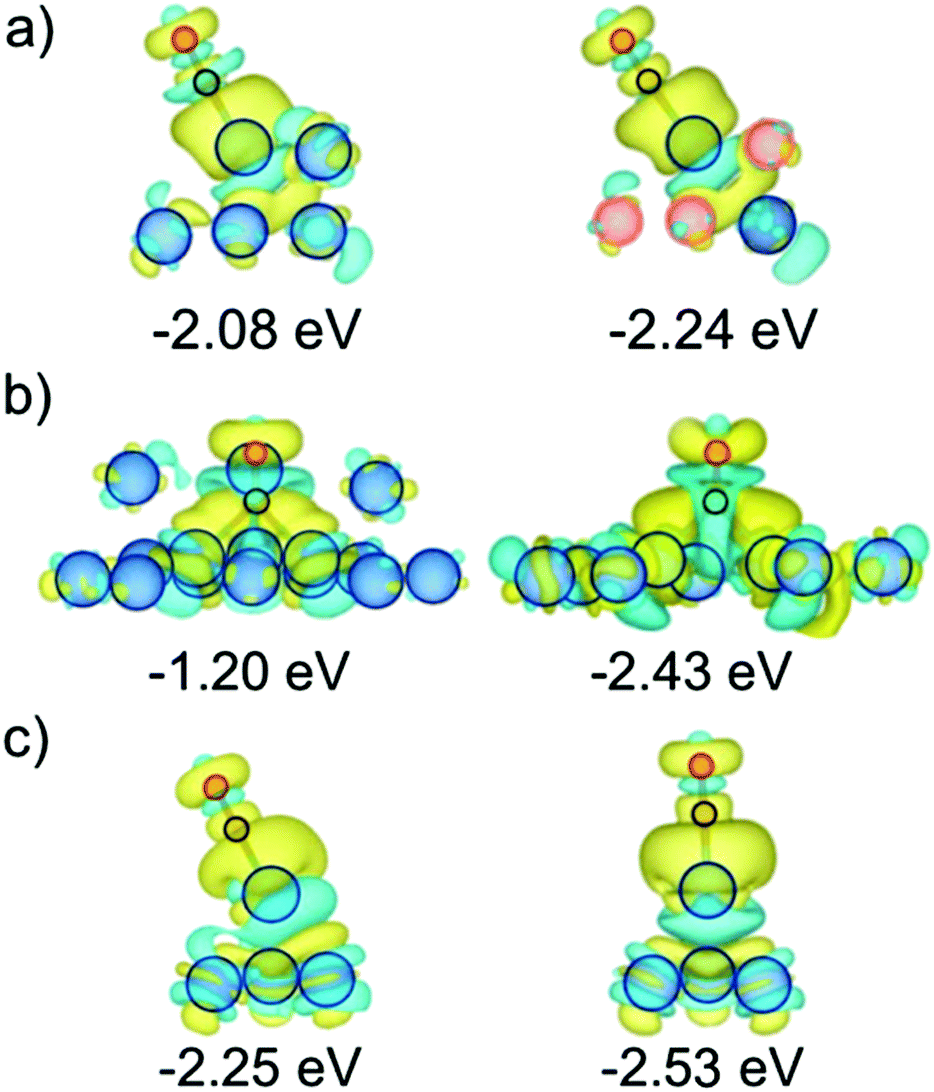 | ||
| Fig. 6 CDD plots of PtCu NPs (right images) with stronger CO adsorption than on the corresponding sites of purely Pt NPs (left images): (a) A site on Pt201vs. it superficially Cu-surrounded, and having subsurface Pt neighbors; (b) CO Adsorption on the centre of 3 Pt atom terrace (111) vacancy of Pt201 and on 3 Pt atom terrace (111) vacancy restructured surface of core@shell Cu79@Pt122; (c) CO Adsorption on terrace (111) Pt adatom of Pt201 and core@shell Cu79@Pt122. Cyan and yellow contours denote electron density depletion and accumulation regions, displayed for values of ±0.001 e Bohr3. | ||
5 Conclusions
To conclude, the CO stripping studies of differently synthesized and commercial PtCu NPs compared to pure Pt NPs reveal notably different CO adsorption behavior. The latter depends on the synthesis method, which defines the size and structure of PtCu NPs indicating that well-shaped particles larger than 2 nm with low Cu content are more resilient towards CO poisoning. However, this CO resistance is compromised for core@shell PtCu NPs of ca. 1.5 nm with a relatively low Pt:Cu content of ∼60:40. Rationalizing these observations, the present DFT simulations on diverse PtCu models show, as expected, a weakening of the CO adsorption on regular sites exposed by the Cu@Pt NPs. Interestingly, this effect is calculated to disappear on such sites as single Pt atoms surrounded by surface Cu ones or under-coordinated Pt atoms resulting, e.g., from the selective oxidation of surface Cu atoms. Indeed, Pt adatoms and few-atom Pt vacancies in Cu@Pt NPs may even strengthen the CO binding, implying an easier poisoning. The effect of these surface defects may get hidden in the presence of a majority of the regular sites, explaining the peak shifts and broadenings detected in the CO stripping voltammograms for differently prepared Cu@Pt NPs. Nevertheless, the effect can become critical for relatively small NPs, highlighting the importance of synthesis procedures in which the appearance of such defects is minimized and setting a size threshold for the employment of PtCu samples as electrocatalysts in PEMFCs. Aside, in order to avoid such CO poisoning enhancement by the surface presence of Cu, or the formation of Pt defects, the PtCu NP synthesis should be driven towards forming a complete and uniform Pt shell, probably favored by a slow cationic exchange and working temperatures enabling the atomic rearrangement within the NPs.
Conflicts of interest
There are no conflicts to declare.Acknowledgements
The work has been supported by the Ministerio de Ciencia y Universidades (MICIUN) RTI2018-095460-B-I00, PGC2018-093863-B-C22, and CTQ2016-78616-R research grants, and by the Spanish Structures of Excellence María de Maeztu program through grant MDM-2017-0767. The research was also funded by the Agencia Estatal de Investigación (AEI, Spain) under project number PID2019-109291RB-I00 and the Generalitat de Catalunya (AGAUR, Spain) through the FI-SDUR PhD scholarship received by J. G. C. (2020 FISDU 00005). The authors are grateful to the CCiT-UB (Scientific and Technological Centers of the Universitat de Barcelona) for their support with the XRD and TEM analyses. The authors are also grateful to Generalitat de Catalunya for the pre-doctoral grant 2018FI-B-00384 for L. V. and partial support through grants 2017SGR13 and XRQTC. F. V. is thankful to Ministerio de Economía y Competitividad (MEC) for his Ramón y Cajal (RYC-2012-10129) research contract. The authors are thankful to Red Española de Supercomputación (RES) for the granted computing time (QS-2020-1-0002 and QS-2020-2-0006).Notes and references
- D. Thompsett, Pt Alloys as Oxygen Reduction Catalysts. Handbook of Fuel Cells. Fundamentals, Technology and Applications, John Wiley & Sons, 2003, New York Search PubMed.
- M. K. Mahapatra and P. Singh, Fuel Cells: Energy Conversion Technology, Future Energy: Improved, Sustainable and Clean Options for our Planet, Elsevier, 2014, London Search PubMed.
- M. K. Debe, Nature, 2012, 486, 43–51 CrossRef CAS PubMed.
- S. Sui, X. Wang, X. Zhou, Y. Su, S. Riffat and C.-J. Liu, J. Mater. Chem. A, 2017, 5, 1808–1825 RSC.
- K. Ruth, M. Vogt and R. Zuber, Development of CO-Tolerant Catalysts on Pt/Ru Catalysts, John Wiley & Sons, 2010, New York Search PubMed.
- P. Janthon, F. Viñes, J. Sirijaraensre, J. Limtrakul and F. Illas, J. Phys. Chem. C, 2017, 121, 3970–3977 CrossRef CAS.
- A. Velázquez-Palenzuela, E. Brillas, C. Arias, F. Centellas, J. A. Garrido, R. M. Rodríguez and P. L. Cabot, J. Catal., 2013, 298, 112–121 CrossRef.
- V. R. Stamenkovic, B. S. Mun, M. Arenz, K. J. J. Mayrhoffer, C. A. Lucas, G. Wang, P. N. Ross and N. M. Markovic, Nat. Mater., 2007, 6, 241–247 CrossRef CAS PubMed.
- Y. Shao, G. Yin and Y. Gao, J. Power Sources, 2007, 171, 558–566 CrossRef CAS.
- M. Gatalo, M. Bele, F. Ruiz-Zepeda, E. Šest, M. Šala, A. R. Kamšek, N. Maselj, T. Galun, P. Jovanovič, N. Hodnik and M. Gaberšček, Angew. Chem., Int. Ed., 2019, 58, 13266–13270 CrossRef CAS PubMed.
- N. Kristian, Y. Yu, J.-M. Lee, X. Liu and X. Wang, Electrochim. Acta, 2010, 56, 1000–1007 CrossRef CAS.
- V. V. Pham, V.-T. Ta and C. Sunglae, Int. J. Hydrogen Energy, 2017, 42, 13192–13197 CrossRef CAS.
- B. B. Bokhonov and D. V. Dudina, J. Alloys Compd., 2017, 707, 233–237 CrossRef CAS.
- M. M. S. Pupo, F. E. López-Suárez, A. Bueno-López, C. T. Menses, K. I. B. Eguiluz and G. R. Salazar-Banda, J. Appl. Electrochem., 2015, 45, 139–150 CrossRef CAS.
- K. M. El-Khatib, R. M. Abdel Hameed, R. S. Amin and A. E. Fetochi, Microchem. J., 2019, 145, 566–577 CrossRef CAS.
- S. Wojtysiak, M. Kamiński, J. Krajczewski, P. Dłużewski and A. Kudelski, Vib. Spectrosc., 2014, 75, 11–18 CrossRef CAS.
- A. Sarkar and A. Manthiram, J. Phys. Chem. C, 2010, 114, 4725–4732 CrossRef CAS.
- S. Baek, K. H. Kim, M. J. Kim and J. J. Kim, Appl. Catal., B, 2017, 217, 313–321 CrossRef CAS.
- A. A. Gokhale, J. A. Dumesic and M. Mavrikakis, J. Am. Chem. Soc., 2008, 130, 1402–1414 CrossRef CAS PubMed.
- Y. Hori, A. Murata, R. Takahashi and S. Suzuki, J. Am. Chem. Soc., 1987, 109, 5022–5023 CrossRef CAS.
- G. Caballero-Manrique, A. Velázquez-Palenzuela, E. Brillas, F. Centellas, J. A. Garrido, R. M. Rodríguez and P. L. Cabot, Int. J. Hydrogen Energy, 2014, 39, 12859–12869 CrossRef CAS.
- I. Mintsouli, J. Georgieva, S. Armyanov, E. Valova, G. Avdeev, A. Hubin, O. Steenhaut, J. Dille, D. Tsiplakides, S. Balomenou and S. Sotiropoulos, Appl. Catal., B, 2013, 136–137, 160–167 CrossRef CAS.
- J. Georgieva, E. Valova, I. Mintsouli, S. Sotiropoulos, S. Armyanov, A. Kakaroglou, A. Hubin, O. Steenhaut and J. Dille, J. Appl. Electrochem., 2014, 44, 215–224 CrossRef CAS.
- V. V. Pryadchenko, V. V. Srabionyan, A. A. Kurzin, N. V. Bulat, D. B. Shemet, L. A. Avakyan, S. V. Belenov, V. A. Volochaev, I. Zizak, V. E. Guterman and L. A. Bugaev, Appl. Catal., A, 2016, 525, 226–236 CrossRef CAS.
- J. Garcia-Cardona, I. Sirés, F. Alcaide, E. Brillas, F. Centellas and P. L. Cabot, Int. J. Hydrogen Energy, 2020, 45, 20582–20593 CrossRef CAS.
- A. Papaderakis, I. Mintsouli, J. Georgieva and S. Sotiropoulos, Catalysts, 2017, 7, 80 CrossRef.
- S. R. Brankovic, J. X. Wang and R. R. Adzic, Electrochem. Solid-State Lett., 2001, 4, A217–A220 CrossRef CAS.
- S. Ambrozic and N. Dimitrov, Electrochim. Acta, 2015, 169, 248–255 CrossRef.
- Y.-G. Kim, J. K. Kim, D. Vairavapandian and J. L. Stickney, J. Phys. Chem. B, 2006, 110, 17998–18006 CrossRef CAS PubMed.
- R. R. Adzic, J. Zhang, K. Sasaki, M. B. Vukmirovic, M. Shao, J. X. Wang, A. U. Milekar, M. Mavrikakis, J. A. Valerio and F. Uribe, Top. Catal., 2007, 46, 249–262 CrossRef CAS.
- S. Papadimitrou, S. Armyanov, E. Valova, A. Hubin, O. Steenhaut, E. Pavlidou, G. Kokkinidis and S. Sotiropoulos, J. Phys. Chem. C, 2010, 114, 5217–5223 CrossRef.
- S. Zhou, B. Varughese, B. Eichhorn, G. Jackson and K. McIlwrath, Angew. Chem., Int. Ed., 2005, 44, 4539–4543 CrossRef CAS PubMed.
- F. Viñes and A. Görling, Chem. – Eur. J., 2020, 26, 11478–11491 CrossRef PubMed.
- Z.-J. Zhao, R. Mu, X. Wang and J. Gong, Langmuir, 2017, 33, 8700–8706 CrossRef CAS PubMed.
- G. Giannakakis, M. Flytzani-Stephanopoulos and E. C. H. Sykes, Acc. Chem. Res., 2019, 52, 237–247 CrossRef CAS PubMed.
- J. Solla-Gullón, V. Montiel, A. Aldaz and J. Clavilier, J. Electrochem. Soc., 2003, 150, E104–E109 CrossRef.
- G. Kresse and J. Furthmüller, Phys. Rev. B: Condens. Matter Mater. Phys., 1996, 54, 11169–11186 CrossRef CAS PubMed.
- G. Kresse and J. Hafner, Phys. Rev. B: Condens. Matter Mater. Phys., 1994, 49, 14251–14269 CrossRef CAS PubMed.
- J. P. Perdew, K. Burke and M. Ernzerhof, Phys. Rev. Lett., 1996, 77, 3865–3868 CrossRef CAS PubMed.
- P. E. Blöchl, Phys. Rev. B: Condens. Matter Mater. Phys., 1994, 50, 17953–17979 CrossRef PubMed.
- G. Kresse and D. Joubert, Phys. Rev. B: Condens. Matter Mater. Phys., 1999, 59, 1758–1775 CrossRef CAS.
- P. Janthon, F. Viñes, J. Sirijaraensre, J. Limtrakul and F. Illas, J. Phys. Chem. C, 2017, 121, 3970–3977 CrossRef CAS.
- F. Viñes, F. Illas and K. M. Neyman, Angew. Chem., Int. Ed., 2007, 46, 7094–7097 CrossRef PubMed.
- M. Happel, N. Luckas, F. Viñes, M. Sobota, M. Laurin, A. Görling and J. Libuda, J. Phys. Chem. C, 2011, 15, 479–491 CrossRef.
- J. Ruvireta, L. Vega and F. Viñes, Surf. Sci., 2017, 664, 45–49 CrossRef CAS.
- L. Vega, H. A. Aleksandrov, R. Farris, A. Bruix, F. Viñes and K. M. Neyman, Mater. Adv., 2021, 2, 6457–6734 RSC.
- H. A. Gasteiger, N. M. Markovic and P. N. Ross Jr., J. Phys. Chem., 1995, 99, 8290–8298 CrossRef CAS.
- G. Caballero-Manrique, E. Brillas, F. Centellas, J. A. Garrido, R. M. Rodríguez and P. L. Cabot, Catalysts, 2015, 5, 815–837 CrossRef CAS.
- J. Garcia-Cardona, F. Alcaide, E. Brillas, I. Sirés and P. L. Cabot, Catalysts, 2021, 11, 724 CrossRef CAS.
- V. V. Pryadchenko, S. V. Belenov, D. B. Shemet, V. V. Srabionyan, L. A. Avakyan, V. V. Volochaev, A. S. Mikheykin, K. E. Bdoyan, I. Zizak, V. V. Guterman and L. A. Bugaev, J. Phys. Chem. C, 2018, 122, 17199–17210 CrossRef CAS.
- V. E. Guterman, S. V. Belenov, A. A. Alekseenko, R. Lin, N. Y. Tabachkova and O. I. Safronenko, Electrocatalysis, 2018, 9, 550–562 CrossRef CAS.
- J. Maya-Cornejo, R. Carrera-Cerritos, D. Sebastián, J. Ledesma-García, L. G. Arriaga, A. S. Aricò and V. Baglio, Int. J. Hydrogen Energy, 2017, 42, 27919–27928 CrossRef CAS.
- A. A. Alekseenko, V. E. Guterman, S. V. Belenov, V. S. Menshikov, N. Y. Tabachkova, O. I. Safronenko and E. A. Moguchikh, Int. J. Hydrogen Energy, 2018, 43, 3676–3687 CrossRef CAS.
- L. Luo, L. Zhang, Z. Duan, A. S. Lapp, G. Henkelman and R. M. Crooks, ACS Nano, 2016, 10, 8760–8769 CrossRef CAS PubMed.
- R. M. Castagna, J. M. Sieben, A. E. Alvarez and M. M. E. Duarte, Int. J. Hydrogen Energy, 2019, 44, 5970–5982 CrossRef CAS.
- M. R. Zamanzad Ghavidel, A. H. A. Monteverde Videla, S. Specchia and E. Bradley Easton, Electrochim. Acta, 2017, 230, 58–72 CrossRef CAS.
- K. J. Andersson and I. Chorkendorff, Surf. Sci., 2010, 604, 1733–1736 CrossRef CAS.
- E. V. Carino, H. Y. Kim, G. Henkelman and R. M. Crooks, J. Am. Chem. Soc., 2012, 134, 4153–4162 CrossRef CAS PubMed.
Footnotes |
| † Electronic supplementary information (ESI) available: Adsorption sites and energies on bridge, hollow, and O-connected top sites. Bader charges on minima and discussion on them. See DOI: 10.1039/d2ma00196a |
| ‡ L. V. and J. G.-C. equally contributed. |
| This journal is © The Royal Society of Chemistry 2022 |