
 Open Access Article
 This Open Access Article is licensed under a Creative Commons Attribution-Non Commercial 3.0 Unported Licence
Scalable and robust silica aerogel materials from ambient pressure drying†
Massimigliano
Di Luigi
a,
Lu
An
 a,
Jason N.
Armstrong
a and
Shenqiang
Ren
*abc
a,
Jason N.
Armstrong
a and
Shenqiang
Ren
*abc
aDepartment of Mechanical and Aerospace Engineering, University at Buffalo, The State University of New York, Buffalo, New York 14260, USA. E-mail: shenren@buffalo.edu
bDepartment of Chemistry, University at Buffalo, The State University of New York, Buffalo, NY 14260, USA
cResearch and Education in Energy, Environment & Water (RENEW), University at Buffalo, The State University of New York, Buffalo, NY 14260, USA
First published on 18th January 2022
Abstract
Aerogels constitute one of the most effective superinsulation materials, typically featuring remarkably low values of thermal conductivity due to their extremely high porosity comprised mostly of mesopores with an average size of approximately 10 nm, as well as considerably high values of specific surface area, all properties that give rise to an outstanding thermal insulator for applications related to energy-saving purposes. However, two of their main disadvantages are (i) a relatively high cost, and (ii) a pearl-necklace structure that result in inherent mechanical brittleness. Here, by leveraging the benefits of ion-exchange sodium silicate solution as a silica source, as well as the use of surfactants, the resulting silica aerogel precursor obtained using the ambient pressure drying (APD) technique is combined with the cellulose-based fiber to produce a composite material that yields an extraordinary combination of significantly low thermal conductivity (28.6 mW m−1 K−1) and high mechanical properties (∼11 MPa maximum compressive stress and Young's modulus of 13.5 MPa in compression at 50% strain). Such a combination of aqueous-based material components and the ambient pressure drying process provides an exceptional low-cost alternative for the production of aerogel-based, eco-friendly solutions that are suitable for energy efficient applications at an industrial scale.
Introduction
Aerogels are renowned for being high-performance thermal insulating materials (ultralow thermal conductivity values even less than that of air) because of their remarkable low density, a direct consequence of their high porosity (typically between 90 and 99%1,2), and comprised mostly of mesopores with an average size of approximately 10 nm.3,4 Other outstanding properties of aerogels include extremely high values of specific surface area (>500 m2 g−1), as well as low dielectric constant and air-like refractive index.5 While these significant advantages of aerogels open up a vast range of applications – such as composite materials, absorbents, sensors, catalysts, storage media, and clothing, to name a few,6 aerogels are predominantly related to energy-saving purposes, particularly as energy-efficient insulation when used in windows,7,8 as aggregates for lightweight cement-based thermal renders,9 and for acoustic purposes amongst their most relevant usability.10Metal oxides, metalloid oxides, polymers, and even noble metals have been employed to produce aerogels.11–15 However, one of the most popular materials used as a base component is silica due to its proneness to form transparent-like products, as well as relative ease of synthesis. Sodium silicate solution (a.k.a. waterglass) has become a very popular and widely used silica source in the synthesis of silica materials by virtue of its significant low cost, which is highly anticipated to increase both the feasibility and large-scale production in the industrial sector. However, waterglass also contains a number of impurities that negatively impact the thermal conductivity of the resulting silica materials. Eradication of sodium ions, and impurities in general, is expected to produce silica aerogels with enhanced properties, mostly due to a more uniform pore size and pore distribution, which could lead to the development of continuous manufacturing processes from ion-exchanged waterglass.16 On the other hand, the supercritical drying (SCD) technique is indispensable for the manufacturing of silica aerogels by appropriately removing the surface tension of the solvent, as well as the capillary pressure gradient that builds up within the pore walls of the wet gels to avoid the potential pore collapse. Additionally, cracking and shrinking of the gels are avoided as the solvent is effectively extracted without developing stress on the pores, thus preserving the porous texture of the gels.17,18 Such a supercritical drying process, in some cases, would entail the need for high-cost autoclaves operating at high temperature (260 °C) and pressure (∼100 bar) in order to heat and evacuate solvents that are typically highly flammable,19 which could also represent a safety hazard during the manufacturing of aerogel products. Both surface modification treatments on the wet gels20 and the addition of compatible surfactants during synthesis, for instance, are relatively simple approaches that could be attempted in order to replace the costly supercritical drying method in favor of the ambient pressure drying (APD) technique. Surfactants, in particular, leverage the ability to form micelles at certain concentrations during hydrolysis, which would facilitate the incorporation of the aqueous phase into the micellar domains in the organic phase that would result in a sharp decrease of the interfacial tension to negligible values,21 therefore allowing the use of APD procedures.
Furthermore, surfactants play a critical role in the sol–gel process for the development of silica aerogels, with only a gel skeleton of macroporous morphology being obtained in the absence of any surfactant as a result of a noticeable phase separation of the condensates of hydrophobic nature.22 Hence, surfactants can be defined as a determinant factor that heavily influences the porosity of the aerogels, while it has been previously reported that a mixture of surfactants is acknowledged to possess improved physicochemical properties due to the synergic effects between cationic and anionic surfactants.23 Cetyltrimethylammonium bromide (CTAB) for instance – one of the most commonly used cationic surfactants – is responsible for the change of the gel skeleton structure from a course granular morphology to continuous fiber as its concentration gradually increases.24 Another benefit of including CTAB during the synthesis of silica aerogels is the decrease of the extent of phase separation that would result from using precursors from the siloxane groups and water as the solvent, with the surfactant being accountable for promoting the miscibility of water and the organic components present, therefore overcoming the strong hydrophobicity of the siloxane networks.25 On the other hand, surfactant induced self-assembly has been reported to adequately control the morphology of porous nanostructures in aerogels, which, in turn, regulates their thermal insulation performance.26
The improvement of the mechanical properties of aerogels ranges from the development of aerogel-like monoliths by different methods such as (i) cross-linking the aerogel particles with polymer cross-linkers of the triacrylate family,27 (ii) the use of a co-precursor approach28,29 as a way to control the cross-linking density – and hence flexibility of the resulting aerogel, and (iii) the use of silica aerogels as unique nanostructured fillers for epoxy nanocomposites.30 Another commonly applied technique incorporates a fiber matrix in the preparation of fiber/aerogel composite products.31–35 Cellulose-based fibers, which can also be referred to as “green” fibers, have become a rather popular alternative over the past couple of years, not only because of their relatively low-cost and environment-friendly nature, but also due to their ease of production – typically obtained from 85% recycled paper – and versatility that has made them a viable alternative for the production of sound absorbers,36 fire-resistant boards,37 and other eco-friendly building materials.
The overall goal being pursued with this work is to capitalize on the low-cost of both ion-exchanged waterglass as the silica source and cellulose-based fiber as the matrix reinforcement agent, as well as to leverage the synergic effect of anionic sodium dodecyl sulfate (SDS) and cationic CTAB as surfactants in order to accomplish aerogel-based solutions that (i) have improved thermal performance, (ii) are commercially feasible for large-scale industrial applications, and (iii) ensure high repeatability and an advantageous performance/cost relationship. The ion-exchange waterglass-based aerogel obtained shows a thermal conductivity as low as 23.4 mW m−1 K−1, with a specific surface area of 412.83 m2 g−1, and a porosity of 97.4%. The developed aerogel precursor/cellulose-fiber composite material possesses hydrophobic capabilities, in addition to an extraordinary combination of significantly low thermal conductivity (28.6 mW m−1 K−1) and improved mechanical properties (∼11 MPa maximum compressive stress and Young's modulus of 13.5 MPa in compression at 50% strain) that results in unique machinability attributes using some of the standard tools as summarized in Fig. 1.
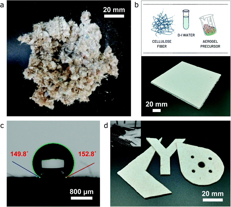 | ||
| Fig. 1 (a) Optical image of cellulose-based fiber from 85% recycled paper. (b) Optical image of the cellulose fiber/silica aerogel composite specimen and outline of its main components. (c) Image showing the hydrophobic capability of the composite specimen after in situ trichlorosilane surface coating. (d) Main image showing different shapes obtained following basic manufacturing operations and the image in the inset illustrating the machinability attributes of the cellulose fiber/silica aerogel composite specimen. | ||
Materials and methods
For preparation of diluted ion-exchange sodium silicate solution (waterglass)
A suggested volume ratio of approximately 0.75/1 would be used for the diluted-sodium-silicate/Amberlite® IRC120 H – hydrogen form resin mix. Firstly, the required cation-exchange resin (Amberlite® IRC120 H – hydrogen form | Sigma Aldrich) is washed 4–5 times for 10 minutes with deionized water before use. During the washing process of the cation-exchange, sodium silicate solution (Technical Grade 40–42° Bé | Fisher Scientific) is diluted to approximately 10% v/v using deionized water (DI H2O) in a beaker, followed by stirring of the solution with a magnetic stirrer for at least 15 min. Finally, the diluted ion-exchange waterglass is passed through an ion-exchange column that has been carefully loaded with the already washed cation-exchange resin.For synthesis of the ion-exchange-sodium-silicate-based aerogel precursor
A flowchart of the synthesis of the ion-exchange-sodium-silicate-based aerogel precursor including both an anionic (SDS) and a cationic surfactant (CTAB) is shown in Fig. 2. Initially, urea [CH4N2O; 98% | Beantown Chemical (BTC)] is added to 400 mL of deionized water [DI H2O] in a beaker using five different molar ratios (namely 4.125, 5.5, 6.875, 11, and 16.5 mol L−1), and the solution is stirred with a magnetic stirrer for at least 60 min until complete dilution takes place. Subsequently, sodium dodecyl sulfate – SDS – [C12H25NaSO4; ≥90% | Sigma Aldrich] and cetrimonium bromide – CTAB – [C19H42BrN; High purity | VWR], with different surfactant ratios and an overall co-surfactant ratio of 0.12 mol L−1, are added to the DI water–urea mixture, with continuous and uniform stirring for at least 120 min or until a homogeneous, white-colour solution is achieved. This will be referred to as Solution A. Typically, the resulting solution will be mixed for at least 6 hours or overnight before the next step. Once fully mixed, the diluted ion-exchange sodium silicate obtained previously is added to the mixture at a proportion of 25 wt% and stirring is continued for at least 2–3 minutes until completely mixed with Solution A to form Solution B. While the last previous step is taking place, hydrochloric acid [HCl(aq); 36.5–38.0% | Capitol Scientific] – 25% v/v HCl/diluted ion-exchange sodium silicate ratio – is added to deionized water [DI H2O] in a small beaker or graduated cylinder to a 50% v/v HCl/DI H2O ratio. Finally, the diluted HCl is added to Solution B and stirring is continued for approximately 2–3 additional minutes until fully blended in the resulting precursor. The pre-aerogel precursor is transferred to a sealed plastic container (target pH of solution ≈ 1.6–1.8), which is closed as tightly as possible before placing it into a pre-heated oven at 80 °C for a period of 24 hours.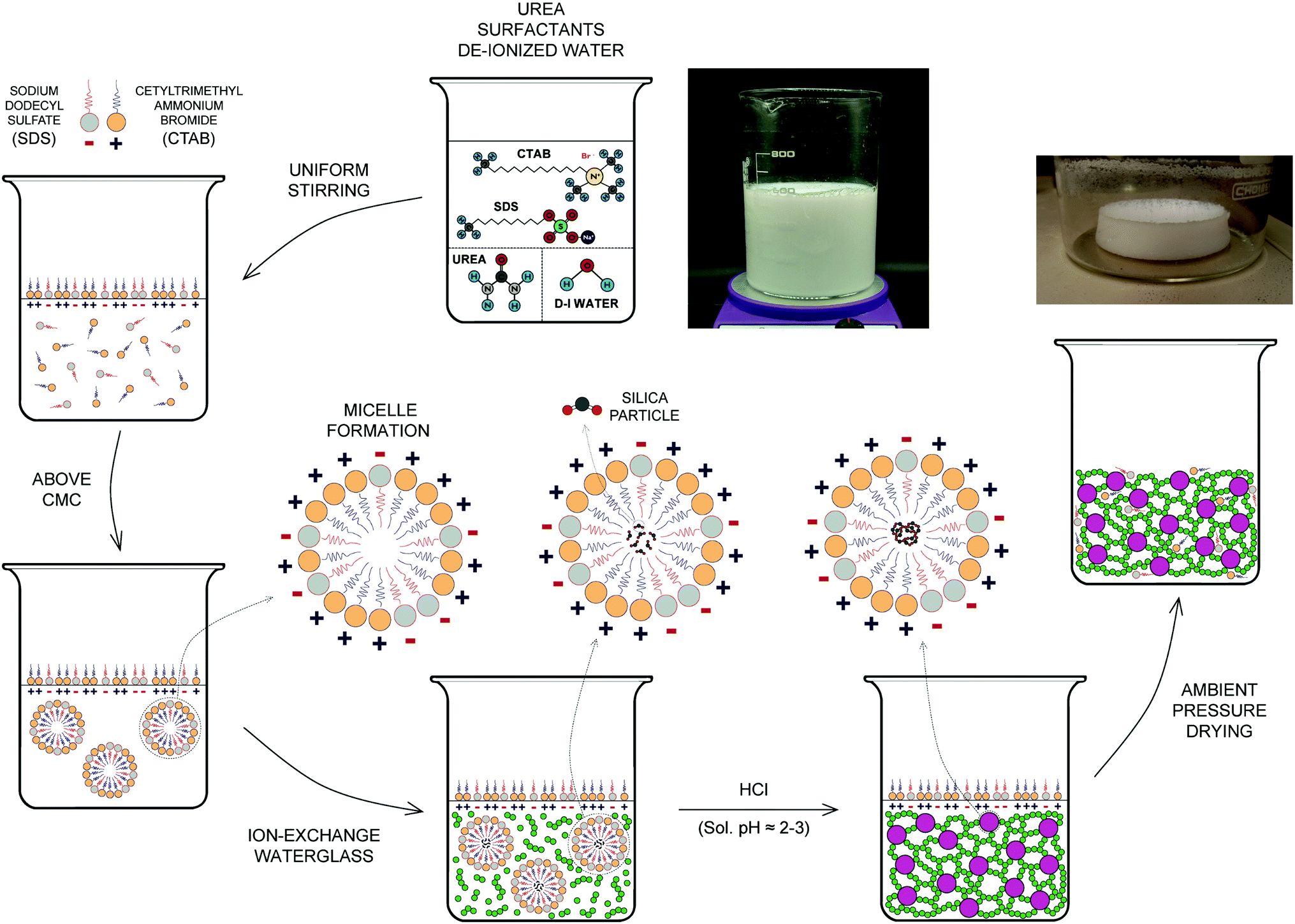 | ||
| Fig. 2 Flowchart of the synthesis of the ion-exchange-sodium-silicate-based aerogel. | ||
Following the completion of the gelation stage, an aerogel precursor of white colour and very smooth aspect – rather fine texture, showing little water separation at the top of the container has formed. The raw precursor is then transferred to a beaker and fully immersed in DI water for washing and aging purposes. The beaker will be placed on a hot plate at approximately 50–55 °C, and DI water should be completely replaced 4–5 times as part of the washing process during a period of at least 24 hours, or until the DI water covering the aerogel precursor is almost fully transparent and all ammonia, and possible unreacted surfactant, have been removed. Upon completion of the washing and aging processes, and once the excess of water is removed from the beaker, the precursor is ready for post-processing. For this work, post-processing would include (a) drying of the aerogel precursor using the ambient pressure drying (APD) technique in a pre-heated oven at 60 °C, followed by the respective calcination of the aerogel samples to 300, 400, 500 and 600 °C, as well as (b) the preparation of aerogel precursor/cellulose-based fiber composite samples.
For preparation of sodium-silicate-based composite samples
Different amounts of cellulose-based fiber (Sanctuary Cellulose Fiber by Greenfiber) have been used in order to study the effect of the aerogel precursor/cellulose-based fiber ratio on the physical, mechanical, and thermal properties of the composite samples. The required amount of cellulose-based fiber is blended with approximately 1.25 L of DI water – to ensure full immersion of the fiber in the liquid – for about 30 seconds using a blender. Following this, the blended fiber is transferred to a larger container and the required volume of the aerogel precursor is added to the mixture, which is thoroughly mixed without any further reaction using an overhead liquid mixer, while gradually adding DI water to complete a volume of approximately 3 L to achieve adequate dispersion of the fiber. A centrifugal-pump-operated composite sample making unit is used to process the previously obtained aerogel precursor/cellulose-based fiber mixture, and the resulting wet composite specimens are afterwards dried in a pre-heated oven at 60 °C for a period of 24–48 hours. Couch sheets are used on both sides of the composite samples during the drying process, in order to increase the water removal rate and ensure the integrity of the samples.Physical, structural, thermal, and mechanical property characterization
The bulk or tapped density of the aerogel samples is calculated from the relationship between the mass of the sample and the volume containing such an amount of the sample, which can be represented by eqn (1): | (1) |
The skeletal density (ρs) is measured by means of a pycnometry system (Micromeritics Accu-Pyc II 1340 Gas Pycnometer), which employs the gas displacement method to measure the volume, and hence determines the density of the solid matter contained within the measuring chamber using highly pressurized helium gas as the measuring medium. The values of porosity of the aerogel samples are then calculated from eqn (2):
 | (2) |
The specific surface area (SSA), pore size, cumulative pore volume, and nanoparticle size of the aerogel samples are determined by means of nitrogen sorption isotherm (adsorption/desorption) analysis using a surface area and porosity analyzer (Micromeritics TriStar II). Previously calcinated aerogel samples (to 600 °C) are pre-treated by heating to 280 °C for 3 hours of degassing of a flowing gas used to remove any form of impurities and contaminants. Samples are subsequently cooled to cryogenic temperatures (−195 °C) under vacuum conditions during the test. The specific surface area (SSA) is calculated from the relative pressure (P/Po from 0.003 to 0.3) data obtained from the adsorption isotherm plot and based on the Brunauer–Emmett–Teller (BET) theory. The pore size and pore volume, on the other hand, are calculated from the desorption branch of the isotherm curve using the method of Barrett, Joyner, and Halenda (BJH) based on the Kelvin model of pore filling.
The structure of the silica aerogel samples is investigated through an X-ray diffraction system (XRD – Rigaku Ultima IV), with copper as the target material for single-crystal diffraction and the X-ray detector rotating at an angle of 2θ from 5° to 80°, these being typical values for data collection of powder patterns. Fourier-transform infrared spectroscopy (FTIR – Agilent Cary 630 FTIR spectrometer) is used to analyze the chemical bonding state of the finely ground aerogel samples, as well as the interfacial bonding of aerogel-based composite samples that could be relevant in order to understand their mechanical performance. The microstructure of both the aerogel and aerogel/fiber composite samples is examined using a focused ion beam scanning electron microscope (FIB-SEM, Carl Zeiss AURIGA CrossBeam).
The thermal conductivity of both the aerogel and aerogel/fiber composite samples is determined through measuring instruments using the steady-state methodology. For aerogel samples, an in-house setup that complies with the ASTM C518 standard, which applies to standard test methods for steady-state thermal transmission properties by means of a heat flow meter apparatus, is used. The PHFS-01e heat flux sensor from FluxTeq has been fitted to the thermal conductivity measurement setup, with the required calibration achieved by virtue of a commercial, translucent aerogel as the reference. The values of thermal conductivity can be calculated using the readings for temperature of top and bottom plates, once steady heat flux between and through the sample has been established. For aerogel/fiber composite samples, on the other hand, the heat flow meter – 100 series (HFM-100) thermal conductivity measurement system from Thermtest – is used, which also complies with the ASTM C518 standard. In a similar fashion, pertinent calibration is accomplished by utilizing commercial samples of extruded polystyrene of appropriate thickness and with a known value of thermal conductivity. Upon insertion of the aerogel/fiber composite sample between the upper and lower plates, and following loading of the calibration file, the system provides the value of thermal conductivity of the sample once the heat flux between the plates, and through the sample, has converged to a constant value over time. In regards to evaluating the thermal stability of aerogel samples, thermogravimetric analysis and differential scanning calorimetry (TGA/DSC) tests were carried out using the TA Instrument DSC SDT Q600. This test provides measurements of weight change (TGA) and true differential heat flow (DSC) on the sample that are heat-treated in a nitrogen atmosphere (with a purge rate of 100 mL per minute) from room temperature (RT – 15 to 25 °C) to 800 °C at a rate of 25 °C per minute.
The mechanical property characterization of the aerogel/fiber composite samples includes uniaxial compression tests of specimens with bulk dimensions of 15 mm × 15 mm and thickness in the region of 4 mm, using a universal test system (Model SSTM-20KN form United Testing Systems) for testing samples up to 20 kN (4500 lbf). Flexural (bending) and tensile tests were also performed to determine both the ultimate strength of the materials under each of the regimes and flexural modulus/elastic modulus (tensile) respectively. For tensile tests, a dog-bone shaped sample was implemented for the determination of tensile strength, while a constant cross-sectional sample was used for the elastic modulus analysis. The same approach (constant cross-section sample) was employed for the flexural tests.
Results and discussion
The schematic drawing shown in Fig. 2 includes a flowchart of the synthesis of the ion-exchange-sodium-silicate-based aerogel precursor comprising both an anionic (SDS) and a cationic surfactant (CTAB). It also highlights the difference between the surfactant molecules, in particular, due to the dissimilar ionic head groups, while confirming the self-association and formation of spherical micelles – mixed micellization – once the critical micelle concentration (CMC) has been reached. The spherical mixed micelles formed in the aqueous solution feature a typical colloidal structure, with the outer barrier composed of perfectly arranged hydrophilic groups and the hydrophobic groups gathering next to each other in the inner core as a result of their amphipathic nature. Following the addition of ion-exchange waterglass, part of the silica source comes together in the inner core of the micelles due to its hydrophobicity associated with a reasonable lack of defined polarity, while the rest remains as suspended silica particles in the solution. Incorporation of the acidic catalyst is expected to trigger the aggregation of silica particles into clusters to initiate the silica network structure, alongside the attachment of the micelles to the formed chains that results in the development of a reinforced network structure during an accelerated gelation rate. The use of urea as an in situ foaming agent, on the other hand, could promote pore formation due to its decomposition in ammonia and carbon dioxide as a result of the chemical reactions existing during solvent condensation under APD conditions. The presence of ammonia would increase the pH of the precursor during condensation, while also accelerating the polymerization of silicon alkoxides34 that could eventually deliver shorter gelation times as highlighted in Fig. S8 (ESI†). The silica aerogel is produced following the APD method.A key factor in improving both the thermal performance and physical properties of waterglass-based aerogels is the implementation of an ion-exchange procedure prior to synthesis of the aerogel precursor. As the diluted waterglass (in de-ionized water) is passed through a bed of cation-exchange resin, sodium ions contained in the aqueous waterglass solution are replaced by hydrogen ions – present in the resin, hence giving rise to an aqueous solution of active silicic acid as a result of the ion-exchange mechanism that takes place. A simplistic scheme of this procedure is shown in Fig. 3a, which typically yields an acidic colloidal solution with pH values between 2 and 4 that contains particles with a diameter of 2 nm or lower.38 Elemental mapping (energy dispersive spectroscopy – EDS) analysis of the aerogel samples that have been synthesized using waterglass-based solutions prior to and after the ion-exchange procedure confirms effective removal of sodium ions from the diluted waterglass, as shown in the tables of composition included in Fig. 3b. Aerogels obtained by means of this purified silica source tend to form a homogeneous bulk monolithic configuration when compared to the non-ion-exchange waterglass counterpart (Fig. S1b and S1a, ESI†), as well as featuring a uniform, dense microstructure in the nanoscale range – as shown in Fig. 3c, in part as a direct effect of the high contents of silica nanoparticles. Furthermore, aerogels produced with ion-exchange waterglass offer a better thermal performance, by virtue of a lower value of thermal conductivity than the non-ion-exchange waterglass specimen (24.9 mW m−1 K−1 and 30.8 mW m−1 K−1 respectively) – as seen from Fig. 3d, which can be attributed to a refined structure skeleton and superlative pore integrity due to the appropriate removal of sodium ions and other impurities that could seemingly develop blockage of the pores and a potential increment of the solid phase of the thermal conductivity of the aerogel.
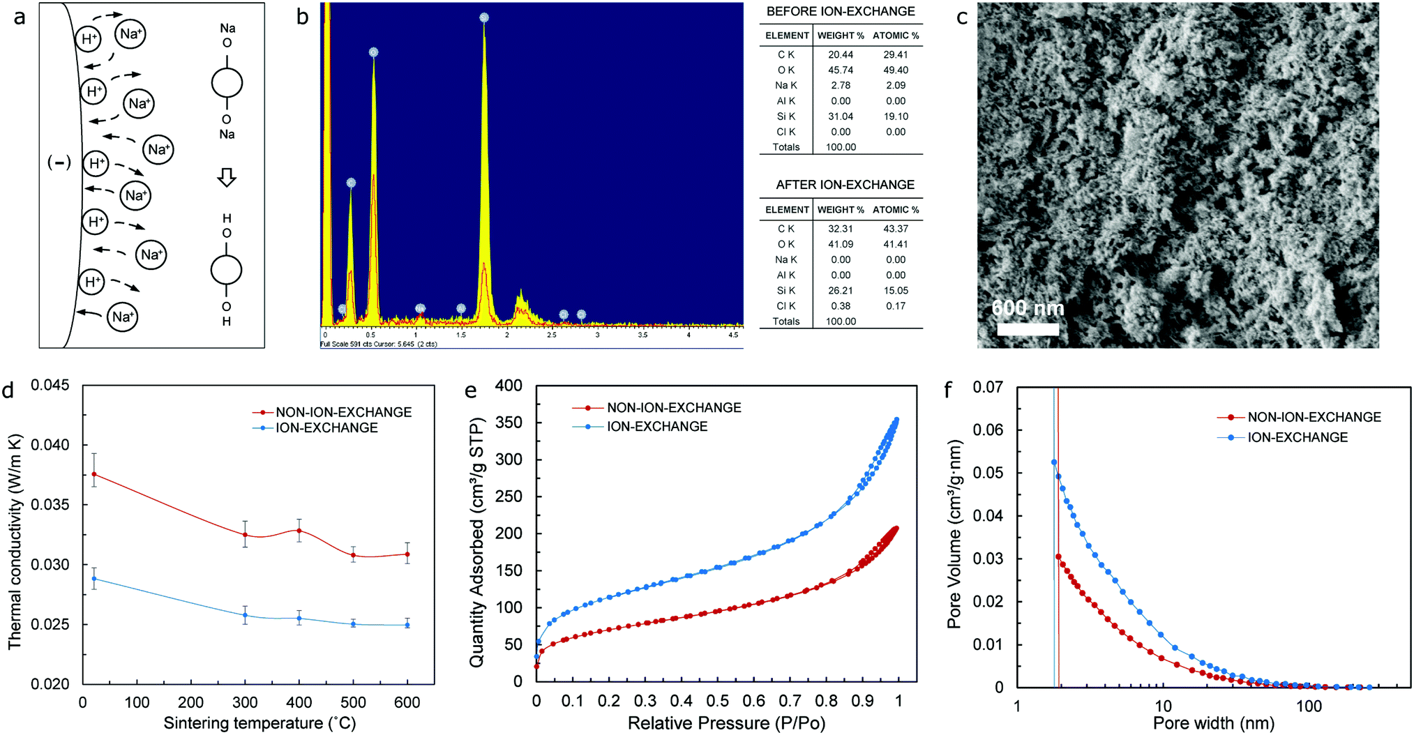 | ||
Fig. 3 (a) Schematic of the ion-exchange waterglass procedure. (b) Elemental mapping (energy dispersive spectroscopy – EDS) analysis of aerogel samples including waterglass before and after the ion-exchange procedure, respectively. (c) SEM image showing the microstructure of the ion-exchange waterglass-based aerogel. (d) Thermal conductivity vs. sintering temperature for both non-ion-exchange and ion-exchange waterglass-based aerogels, respectively. (e and f) Isotherm curve and pore volume plots from BET/BJH tests for both non-ion-exchange and ion-exchange waterglass-based aerogels respectively. All results correspond to aerogel specimens (sintered to 600 °C) with a 1![[thin space (1/6-em)]](https://www.rsc.org/images/entities/char_2009.gif) :1 SDS/CTAB ratio, and urea molar ratios of 4.125 mol L−1 (b–d) and 6.875 mol L−1 (e and f) respectively. :1 SDS/CTAB ratio, and urea molar ratios of 4.125 mol L−1 (b–d) and 6.875 mol L−1 (e and f) respectively. | ||
A thorough analysis of the values of thermal conductivity of aerogel samples with different urea molar ratios and weight percentage of ion-exchange waterglass suggests that, for a one-to-one ratio (1:1) of the surfactants (SDS/CTAB), a urea molar ratio of 4.125 mol L−1 and 25 wt% ion-exchange waterglass yield an optimum thermal performance by virtue of lower values of thermal conductivity (24.9 mW m−1 K−1) as shown in Fig. S2 (ESI†). Two opposite trends can be noticed for such a surfactant ratio, with (i) values of thermal conductivity tending to increase (24.9 mW m−1 K−1 for 4.125 mol L−1 of urea, to 27.8 mW m−1 K−1 for 16.5 mol L−1 of urea) and (ii) values of porosity decreasing as the quantity of urea increases (96.3% for 4.125 mol L−1 of urea, to 87.3% for 16.5 mol L−1 of urea) – as shown in Fig. S3 (ESI†), which could be the result of both a concurrent increment of the average pore size of the aerogel and a decrease in the number of pores that would presumably introduce a simultaneous increase in the thermal conductivity of the aerogel in the gas and solid phases, respectively.
On the other hand, an assessment of the specific surface area (SSA) as a critical physical property of aerogels shows that for the same one-to-one ratio (1:1) of the surfactants (SDS/CTAB), the highest value of SSA (399.2 m2 g−1) occurs at a urea molar ratio of 6.875 mol L−1 and 25 wt% ion-exchange waterglass, results obtained from tests based on the Brunauer–Emmett–Teller (BET) adsorption method. In a similar fashion to the case of the analysis of thermal conductivity, this highest value of SSA corresponds to one of the lowest values of porosity (∼89.4%) as shown in Fig. S4 (ESI†). The above highlights the importance of both pore size and porosity on the volume of gas adsorbed at standard temperature and pressure (STP) required to produce an apparent monolayer on the surface of the sample, this amount of the adsorbate gas being the most critical factor when determining the SSA of a powder. Moreover, Fig. 3e and f confirm that aerogels obtained from ion-exchange waterglass would both (i) absorb a much higher quantity of gas during the BET test, and (ii) have a larger pore volume than the non-ion-exchange waterglass aerogel, respectively, which could be a direct consequence of the urea present in the precursor that acts as a polymerization accelerator of the purified waterglass, hence freezing the structure prior to any macroscopic phase separation taking place39 and preserving structural homogeneity during APD of the aerogels.
The results obtained from thermal conductivity tests at room temperature (RT – 15 to 25 °C) of aerogel samples with different surfactant ratios indicate that the lowest values occur for a 1:2 ratio (SDS/CTAB) – as shown in Fig. 4a, which would happen for both the original state and sintered specimens (to 300 °C, 400 °C, 500 °C, and 600 °C), respectively. Typically, the SEM images of these aerogels show a three-dimensional type network structure, which is particularly noticeable in specimens that have been sintered to 600 °C as a mechanism to remove the organic matter and preserve the mesoporous microstructure typical of silica aerogels as depicted in Fig. 4b and Fig. S5 (ESI†). A CTAB ratio of 0.66/1 (i.e. 1:2 SDS/CTAB) yields the lowest value of thermal conductivity at 23.4 mW m−1 K−1, while a complete opposite trend is observed in regards to porosity with significantly high values of 97.4% and 98.3% for CTAB ratios of 0.66/1 and 0.75/1, respectively, as shown in Fig. 4c, which highlights the direct, but inverse, relationship that exists between these two properties. It is important to notice that even though the overall molar ratio of the combined surfactants remains the same (0.12 mol L−1), only one particular ratio of the surfactants would yield superlative thermal performance by virtue of the mixed micelle formation of the anionic (SDS) and cationic (CTAB) surfactants that takes place within the mixed SDS/CTAB system as a result of the attractive interactions between the monomers.23 Moreover, mixed micelles not only exhibit different physicochemical properties according to their surfactants’ composition ratio, but these can also host different amounts of silica from the waterglass in their core that will eventually break through the barrier that has been formed by the surfactants’ system and form the silica aerogel backbone. Consequently, silica contents in the aerogel will be determined by the nature of the mixed micelles, which is, in turn, defined by the surfactants’ composition ratio.
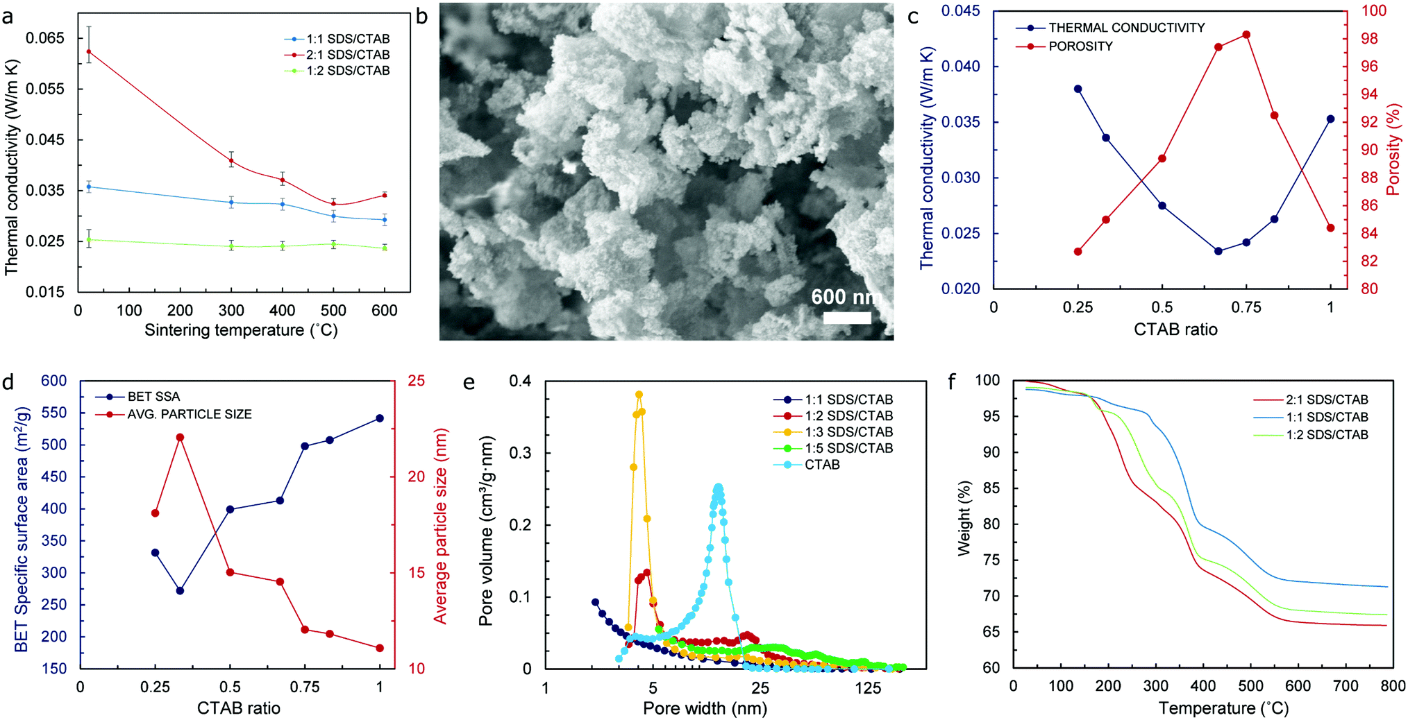 | ||
| Fig. 4 (a) Thermal conductivity vs. sintering temperature for ion-exchange waterglass-based aerogels with different co-surfactant ratios. (b) SEM image showing the typical mesoporous microstructure of ion-exchange waterglass-based aerogels. (c) Thermal conductivity and porosity vs. CTAB ratio; (d) BET SSA and average particle size vs. CTAB ratio for silica aerogels with optimal quantities of ion-exchange waterglass and urea. (e) Pore volume plot from BET/BJH tests, and (f) weight loss % vs. temperature curves (TGA test) for aerogel samples with different co-surfactant ratios and optimal quantities of ion-exchange waterglass. All results correspond to aerogel specimens (sintered to 600 °C) with 6.875 mol L−1 of urea and 25 wt% ion-exchange waterglass. | ||
In regard to the values of specific surface area (SSA), from the lowest value obtained (271.96 m2 g−1) for a CTAB ratio of 0.33/1 (or 2:1 SDS/CTAB), the SSA of sintered specimens increases gradually until reaching a maximum value of 541.6 m2 g−1 for the CTAB only sample (control value) as shown in Fig. 4d. Nevertheless, the values of the average particle size indicate an opposite tendency, achieving the highest value of approximately 22 nm for a CTAB ratio of 0.33/1, which then decreases gradually to the lowest value of 11.08 nm for the CTAB only specimen. The values of porosity, on the other hand, increase steadily as the CTAB ratio also increases, although it starts to decrease at a CTAB ratio of 0.75/1 (or 1:3 SDS/CTAB) – after reaching a maximum value in the vicinity of 98%, to drop to approximately 84% for the CTAB only sample as indicated in Fig. 4c. The fact that the values of SSA keep increasing beyond such a CTAB ratio of 0.75/1 where the values of porosity decrease by almost 14% can be attributed to a significant improvement of the pore volume values for specimens with a CTAB ratio beyond this mark – as shown in Fig. 4e, which will actually produce higher values of surface area of the pores, even though the number of these seem to reduce by a considerable fraction. Data in connection with these relevant aerogel properties (namely thermal conductivity, SSA, pore width, average particle size, and porosity) can be found in Table S1 (ESI†).
The thermal stability of the waterglass-based aerogels with different surfactant composition ratios was investigated by means of TGA/DSC analysis that was performed from RT (15 to 25 °C) to 800 °C. In all cases, a congruent pattern could be observed, with weight % vs. temperature curves shown in Fig. 4f indicating that the initial weight loss occurs at around 70 °C due to the removal of water molecules that are still present in the specimens. This is followed by a sharp weight loss that begins at around 200–300 °C – depending on the composition ratio of the surfactants in the aerogels, and that continues until approximately 550 °C for all samples analyzed, which could be attributed to the thermal degradation of organic matter existing in the specimens. The thermal degradation of the aerogel samples beyond 550 °C is almost negligible, with the resulting weight loss totaling approximately 30% of their initial mass once the temperature has reached 800 °C. This difference in weight loss could be associated with the removal of different amounts of not only organic molecules from the surfactants and urea resulting essentially from the dissimilar chemical reactions present during the sol–gel process, but also the residual, unreacted silica that had not been effectively extracted during the washing stage of the aerogel precursor. From the X-ray diffraction (XRD) spectra obtained – and shown in Fig. S6 (ESI†), only a rather noticeable peak at 2θ approximately equal to 22° is observed in all aerogel specimens, which is typical of their amorphous structure and directly related to the bonding angle of the Si–O–Si siloxane functional groups40 that form the backbone of the silica aerogels.
Aerogels are renowned for their brittleness and fragility. When produced in bulk, monolithic form, they possess some inherent mechanical strength, although they can rapidly collapse once the value of maximum allowable stress is achieved due to their inability to withstand loads beyond the elastic regime. Moreover, cyclic load schemes are rarely feasible since their structure is substantially damaged when the load range within the elastic regime is accomplished. One of the most common practices to overcome such brittleness and fragility is to mix fibers with the aerogel precursor – prior to the drying stage – to produce composite specimens, in order to (i) take advantage of the physical properties of the fiber to introduce some degree of elasticity to the resulting product, as well as (ii) improving the thermal performance of fiber-based products by virtue of the aerogel precursor being used. Fig. 5a shows the schematic of the methodology that has been used for the preparation of cellulose fiber/aerogel composite specimens, a scalable procedure that is thoroughly explained in the materials and methodology section. Since vacuum filtration is implemented in order to remove all the liquid from the fiber/precursor mix and allow for the effortless extraction of the sample from the experimental setup, a rather neat layer-upon-layer fiber/aerogel arrangement is typically achieved as revealed by the SEM images of the cross-section of the specimens shown in the insets to Fig. 5b and c. It is worth emphasizing that when optimal quantities of the aerogel precursor are used, the methodology reported promotes a superior cross-linking between the fiber and aerogel as illustrated in the SEM images included in Fig. 5c (both main and inset), while Fig. 5b, on the other hand, shows the microstructure of both the surface and cross-section (main and inset, respectively) of a composite specimen with low thermal performance (high value of thermal conductivity) due to a noticeably poor cross-linking between the fiber and aerogel.
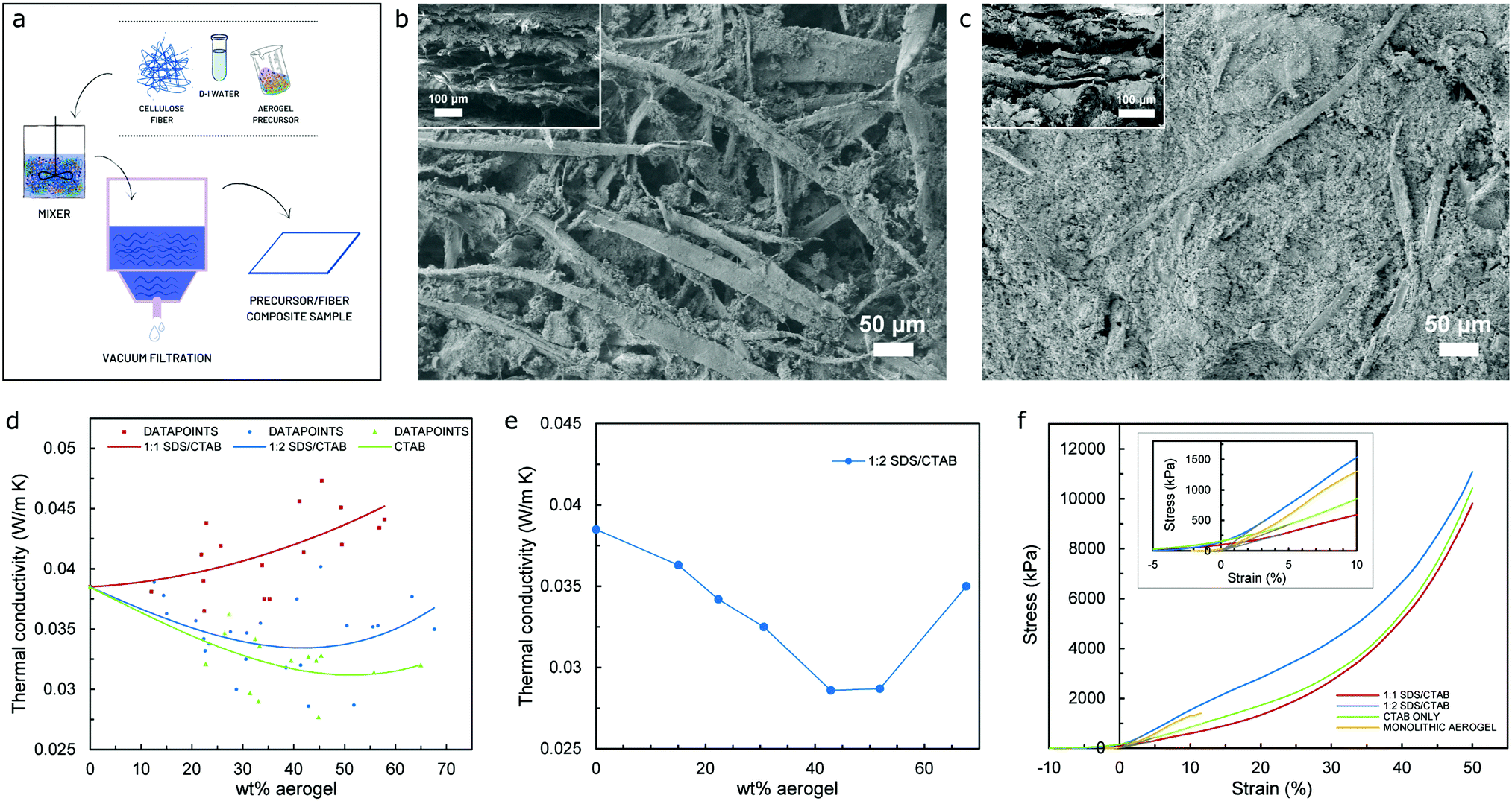 | ||
| Fig. 5 (a) Schematic of the fiber/aerogel composite specimen procedure. (b and c) SEM image showing the microstructure of surface and cross-sectional area (inset) for composite specimens with poor and good thermal performance, respectively. (d and e) Thermal conductivity vs. aerogel weight% for composite specimens with different co-surfactant ratios – includes the resulting trend for all samples produced and thickness dependence, respectively. (f) Stress vs. strain curves of composite specimens with different co-surfactant ratios and monolithic aerogel samples, respectively. | ||
Fig. 5d, on the other hand, presents the results of thermal conductivity in relation to the quantity of aerogels contained for the entire group of samples – including the three different aerogel precursors used, with the curves shown representing each of the trends for the full set of datapoints obtained following thermal conductivity tests. Logarithmic fit has been used for curve fitting due to the nature of the dataset, which only presents one substantial change in the trend (minimum values of thermal conductivity) to then follow a definite increasing tendency as the wt% of aerogel increases. Analysis of the trendlines suggest that as the percentage of CTAB increases in the aerogel precursor, the value of thermal conductivity of the composite samples tends to decrease, with the lowest values belonging to the CTAB only precursor (overall lowest value of 27.7 mW m−1 K−1) that has been used as a control value, while specimens from the 1:2 SDS/CTAB ratio follow closely with and overall lowest value of thermal conductivity of 28.6 mW m−1 K−1. Such a tendency could be attributed to the distinct effect of the different concentrations of cationic surfactant (CTAB) on the resulting silica aerogel structure for the different aerogel precursors used, which may have interacted distinctively with the cellulose fiber, hence producing different fiber/aerogel morphologies that would in turn introduce dissimilarity in the thermal performance of the specimens. Since diverse concentrations of CTAB would have a direct effect on the micelle being formed during hydrolysis, which in turn would affect both the resulting silica nanoparticle, porosity, and pore size of the aerogel amongst its most relevant physicochemical properties, different cross-linking effects of the fiber/aerogel duo would occur, hence affecting the thermal conductivity of the produced specimen in both the gas and the solid phase. Furthermore, the values of thermal conductivity versus weight percentage of the aerogel for groups of composite samples with a similar thickness (∼2.2 mm) for the 1:2 SDS/CTAB aerogel precursor are shown in Fig. 5e, which does not only fairly correlate with the results in Fig. 5d, but also confirms that the best thermal performance for the SDS/CTAB based precursor (1:2 ratio) – by means of the lowest values of thermal conductivity at 28.6 mW m−1 K−1 – occurs for a weight percentage of the aerogel of approximately 42%, this value being in agreement with that reported by research work previously carried out on surfactant-based aerogels.35
Uniaxial compression tests were performed to characterize the mechanical performance, with stress vs. strain curves for bulk and composite samples shown in Fig. 5f. In order to more effectively acquire meaningful results from the data obtained after the tests, any readings related to both slack and alignment/seating of the sample (which is not a true response of the sample, but an artifact of its geometry) has been disregarded by including a “toe compensation” portion of the curve that would help us obtain more accurate values of the elastic modulus. The calculation of the elastic or Young's modulus has been performed using the tangent modulus in the linear region of the stress–strain curve up to 10% strain, hence ensuring that the sample is still in the elastic regime. The bulk monolithic aerogel sample fractured at approximately 15% strain with a maximum stress of 1405 kPa. The composite specimens were compressed to 50% strain and then unloaded, with the obtained results indicating that all composite samples could withstand at least 50% strain without collapsing. Even though some of the composite specimens (namely 1:1 SDS/CTAB and CTAB only) yield compressive stresses at 15% strain that are lower than that of the monolithic aerogel specimen at the fracture point, the composites can be compressed further and remain still fully functional after going through a full cycle of loading/unloading. Furthermore, all composite specimens tested allow a maximum compressive stress that is notably superior (up to about 11 MPa as presented in Table S2, ESI†) to those previously reported – in the region of 20 kPa at 40% strain – for composite samples using ceramic fibers.34,35 This can be attributed to the nature of the fibril used, with cellulose-based fibers being highly hydrophilic in essence, hence promoting a strong bonding with both adjacent threads and interfacing the aerogel precursor during the drying stage. Similarly, improvement in the Young's modulus (in compression) when compared to composite specimens using ceramic fibers34 has been observed, with a maximum value of 13.5 MPa for the cellulose-based samples (as reported in Table S2, ESI†) in contrast to 55 kPa as the highest value for the former.
On the other hand, tensile and flexural (or bending) tests were also carried out to understand the performance of the cellulose-fiber-based materials under these different stress regimes. From the plots shown in Fig. S10 (ESI†), the material prepared using the 1:1 SDS/CTAB aerogel precursor shows superlative mechanical properties under tensile and bending loads (∼1.3 MPa and 1.85 MPa for tensile and flexural strength, respectively), when compared with those specimens produced using the other precursors being analysed. Such a trend in both tension and bending – where a portion of the sample is subject to tensile stress, which is completely the opposite one during uniaxial compression, emphasizes that the in-plane and out-of-plane properties of the materials vary from one to the other, thus suggesting that a different fiber/precursor cross-linking mechanism may be present and could have an impact on the structural properties of the fiber/aerogel compound. Nevertheless, these superior mechanical properties and rigidity of the samples translate into outstanding machinability attributes by easily enduring some of the standard manufacturing operations, specifically sawing as one of the most useful processes (depicted in Fig. 1d), which undeniably opens up a vast range of applications for aerogel-based products in a number of industrial sectors.
Conclusions
An all-around low-cost strategy for the production of silica-based aerogel composite materials is proposed in this research work, which comprise purified sodium silicate solution (also referred to as waterglass) and commercial cellulose-based fibers (∼85% newsprint) as fundamental components. An economical, straightforward ion-exchange procedure has been used for the purification of the waterglass, yielding a colloidal solution with high contents of silica nanoparticles that result in better thermal performance due to the presence of a refined structure skeleton and superlative pore integrity following the removal of sodium ions and other impurities. Optimizing the quantities of urea and surfactants (i.e. both the anionic SDS and the cationic CTAB), which were introduced as pore developing agents during the sol–gel process to allow for the implementation of ambient pressure drying techniques of both aerogels and composite specimens, proved to be instrumental in accomplishing superior physicochemical properties such as porosity, density, cumulative pore volume, and specific surface area that would have a direct impact on the improvement of values of the thermal conductivity of the aerogel-based materials.Through a scalable, vacuum-filtration-assisted procedure, along with the inclusion of cellulose-based fibers generated from recycled paper and widely available, composite specimens have been produced, which not only achieved outstanding values of maximum compressible strength at relatively low strain when compared with the ceramic-fiber-based counterparts, but also resulted in an improved balance between elasticity and rigidity that allows for easy, safe machinability of the generated fiber/aerogel products. Such attributes position these functional materials as promising alternatives in the development of thermal-performance-enhanced products with a broad range of applicability at an industrial scale.
Author contributions
All authors discussed the results and commented on the manuscript. M. D. and S. R. designed all experiments. M. D. prepared the samples and conducted experiments regarding mechanical and thermal properties, as well as structural and physicochemical characterization. J. A. conducted the partial mechanical study. S. R. conceived the project and directed the research. All authors contributed to the writing and editing of the manuscript.Conflicts of interest
There are no conflicts to declare.Acknowledgements
This work at University at Buffalo is supported by the US. Department of Energy's Office of Energy Efficiency and Renewable Energy (EERE) under the Building Technology Office (BTO) Award Number DE-EE0008675.Notes and references
- B. M. Gauthier, S. D. Bakrania, A. M. Anderson and M. K. Carroll, J. Non-Cryst. Solids, 2004, 350, 238–243 CrossRef CAS.
- J.-H. Kim, J.-H. Ahn, J.-D. Kim, D.-H. Lee, S.-K. Kim and J.-M. Lee, Materials, 2021, 14(7), 1790 CrossRef CAS PubMed.
- S. Iswar, S. Galmarini, L. Bonanomi, J. Wernery, E. Roumeli, S. Nimalshantha, A. M. B. Ishai, M. Lattuada, M. M. Koebel and W. J. Malfait, Acta Mater., 2021, 213, 116959 CrossRef CAS.
- H. Cai, Y. Jiang, J. Feng, S. Zhang, F. Peng, Y. Xiao, L. Li and J. Feng, Mater. Des., 2020, 191, 108640 CrossRef CAS.
- A. S. Dorcheh and M. Abbasi, J. Mater. Process. Technol., 2008, 199(1-3), 10–26 CrossRef.
- J. L. Gurav, I.-K. Jung, H.-H. Park, E. S. Kang and D. Y. Nadargi, J. Nanomater., 2010, 2010 Search PubMed.
- C. Garnier, T. Muneer and L. McCauley, Build. Environ., 2015, 94, 231–238 CrossRef.
- U. Berardi, Appl. Energy, 2015, 154, 603–615 CrossRef.
- M. de Fátima Júlio, A. Soares, L. M. Ilharco, I. Flores-Colen and J. de Brito, Cem. Concr. Compos., 2016, 72, 309–318 CrossRef.
- P. C. Thapliyal and K. Singh, J. Mater., 2014, 2014, 10 Search PubMed.
- A. Benad, F. Jürries, B. Vetter, B. Klemmed, R. Hübner, C. Leyens and A. Eychmüller, Chem. Mater., 2018, 30(1), 145–152 CrossRef CAS.
- J. Shen, Q. Li, B. Zhou, J. Wang and L. Chen, J. Non-Cryst. Solids, 1997, 220(1), 102–106 CrossRef CAS.
- A. Harley-Trochimczyk, T. Pham, J. Chang, E. Chen, M. A. Worsley, A. Zettl, W. Mickelson and R. Maboudian, Adv. Funct. Mater., 2016, 26(3), 433–439 CrossRef CAS.
- T. Wang, M.-C. Long, H.-B. Zhao, B.-W. Liu, H.-G. Shi, W.-L. An, S.-L. Li, S.-M. Xu and Y.-Z. Wang, J. Mater. Chem. A, 2020, 8(36), 18698–18706 RSC.
- H. Wang, Q. Fang, W. Gu, D. Du, Y. Lin and C. Zhu, ACS Appl. Mater. Interfaces, 2020, 12(47), 52234–52250 CrossRef CAS PubMed.
- T. Kim, S. Hwang and S. Hyun, Ind. Eng. Chem. Res., 2008, 47(18), 6941–6948 CrossRef CAS.
- J. Estella, J. C. Echeverría, M. Laguna and J. J. Garrido, Microporous Mesoporous Mater., 2007, 102(1-3), 274–282 CrossRef CAS.
- T. Y. Wei, T. F. Chang, S. Y. Lu and Y. C. Chang, J. Am. Ceram. Soc., 2007, 90(7), 2003–2007 CrossRef CAS.
- P. B. Sarawade, J.-K. Kim, A. Hilonga and H. T. Kim, Powder Technol., 2010, 197(3), 288–294 CrossRef CAS.
- Z. Li, S. Zhao, M. M. Koebel and W. J. Malfait, Mater. Des., 2020, 193, 108833 CrossRef CAS.
- D. o. L. Goldfarb, J. J. de Pablo, P. F. Nealey, J. P. Simons, W. M. Moreau and M. Angelopoulos, J. Vac. Sci. Technol., B: Microelectron. Nanometer Struct. – Process., Meas., Phenom., 2000, 18(6), 3313–3317 CrossRef CAS.
- V. G. Parale, K.-Y. Lee and H.-H. Park, J. Korean Ceram. Soc., 2017, 54(3), 184–199 CrossRef CAS.
- M. S. Alam, R. Ragupathy and A. B. Mandal, J. Dispersion Sci. Technol., 2016, 37(11), 1645–1654 CrossRef CAS.
- X. Li, Z. Yang, K. Li, S. Zhao, Z. Fei and Z. Zhang, J. Sol-Gel Sci. Technol., 2019, 92(3), 652–661 CrossRef CAS.
- X. Cheng, C. Li, X. Shi, Z. Li, L. Gong and H. Zhang, Mater. Lett., 2017, 204, 157–160 CrossRef CAS.
- R. Yang, J. Wang, L. An, D. Petit, J. N. Armstrong, Y. Liu, Y. Huang, Y. Hu, Z. Shao and S. Ren, J. Mater. Chem. C, 2020, 8(30), 10319–10324 RSC.
- H. Maleki, L. Durães and A. N. Portugal, J. Phys. Chem. C, 2015, 119(14), 7689–7703 CrossRef CAS.
- G. Hayase, K. Kanamori, K. Kazuki and T. Hanada, In Synthesis of new flexible aerogels from MTMS/DMDMS via ambient pressure drying, IOP Conference Series: Materials Science and Engineering, IOP Publishing, 2011, p 032013 Search PubMed.
- S. Li, H. Ren, J. Zhu, Y. Bi, Y. Xu and L. Zhang, J. Non-Cryst. Solids, 2017, 473, 59–63 CrossRef CAS.
- S. Salimian and A. Zadhoush, J. Porous Mater., 2019, 26(6), 1755–1765 CrossRef CAS.
- C.-Y. Kim, A.-R. Jang, B.-I. Kim and D.-H. Suh, J. Sol-Gel Sci. Technol., 2008, 48(3), 336–343 CrossRef CAS.
- A. Ślosarczyk, Nanomaterials, 2021, 11(2), 258 CrossRef PubMed.
- H. Wu, Y. Chen, Q. Chen, Y. Ding, X. Zhou and H. Gao, J. Nanomater., 2013, 2013 Search PubMed.
- L. An, J. Wang, D. Petit, J. N. Armstrong, K. Hanson, J. Hamilton, M. Souza, D. Zhao, C. Li and Y. Liu, Nano Lett., 2020, 20(5), 3828–3835 CrossRef CAS PubMed.
- L. An, J. Wang, D. Petit, J. N. Armstrong, C. Li, Y. Hu, Y. Huang, Z. Shao and S. Ren, Appl. Mater. Today, 2020, 21, 100843 CrossRef.
- J.-O. Yeon, K.-W. Kim, K.-S. Yang, J.-M. Kim and M.-J. Kim, Constr. Build. Mater., 2014, 70, 494–500 CrossRef.
- P. Moreno, N. Villamizar, J. Perez, A. Bayona, J. Roman, N. Moreno and N. S. M. Cardozo, Clean Technol. Environ. Policy, 2021, 1–10 Search PubMed.
- M. J. Schick and T. Hubbard, Surfactant Science Series: Chapter of Colloid Science 2006 Search PubMed.
- K. Kanamori, M. Aizawa, K. Nakanishi and T. Hanada, Adv. Mater., 2007, 19(12), 1589–1593 CrossRef CAS.
- L. Wa, L. Fengyun, Z. Fanlu, C. Mengjing, C. Qiang, H. Jue, Z. Weijun and M. Mingwei, Appl. Surf. Sci., 2015, 353, 1031–1036 CrossRef CAS.
Footnote |
| † Electronic supplementary information (ESI) available: Details of the ion-exchange procedure, microstructure, thermal conductivity, porosity, surface area, pore width, average particle size, and structural characterization of aerogel specimens; mechanical properties of cellulose fiber/aerogel composite specimens. See DOI: 10.1039/d1ma01086g |
| This journal is © The Royal Society of Chemistry 2022 |