
 Open Access Article
 This Open Access Article is licensed under a Creative Commons Attribution-Non Commercial 3.0 Unported Licence
CsPbI3 perovskite quantum dot solar cells: opportunities, progress and challenges
Jahangeer
Khan†
,
Ihsan
Ullah†
and
Jianyu
Yuan
 *
*
Institute of Functional Nano & Soft Materials, Jiangsu Key Laboratory for Carbon-Based Functional Materials & Devices, Soochow University, Suzhou 215123, China. E-mail: jyyuan@suda.edu.cn
First published on 31st December 2021
Abstract
Due to the rapid increase in population, total electricity demands have been quickly increasing. Under this circumstance, renewable energy technologies such as photovoltaic (PV) materials need to be urgently developed. Among these diverse PV devices, solution-processable materials like organic semiconductors and inorganic quantum dots (QDs) are desirable for designing lightweight, low-cost, semi-transparent, and portable solar cells. All-inorganic CsPbI3 perovskite QDs have quickly emerged as a rising star for QD PV materials and have achieved a remarkable efficiency of over 16% via advanced surface chemistry and device engineering. In this review, we first summarize the latest breakthroughs in perovskite technology via various strategies such as the optimization of synthesis procedures, surface modifications, and solid QD inks. In addition, we briefly discuss device architecture engineering for achieving higher PV efficiency and improved long-term stability. Finally, we present the next steps in QD preparation, processing, and architecture to further improve the device performance.
 Jianyu Yuan | Jianyu Yuan is currently a Professor at the Institute of Functional Nano & Soft Materials (FUNSOM), Soochow University. He received his PhD degree from Soochow University in 2016. In 2014–2015, he worked at the University of California, Santa Barbara (UCSB), as a joint PhD student, and in 2018, he was a visiting professor at National Renewable Energy Laboratory (NREL). Currently, his research interests include the design and synthesis of functional conjugated polymers, perovskite nanocrystals and organic/nanocrystal hybrid systems for photovoltaic and other emerging optoelectronic applications. |
1. Introduction
One of the most challenging hurdles towards developing a power and energy sector using traditional energy generation sources is the globally increasing energy demands, cost, and negative environmental impact due to the immense amount of fossil fuel emissions.1–3 To overcome these issues, renewable and clean energies are one of the most promising and suitable approaches. Photovoltaic systems, which are devices that convert sunlight into electrical power, are one of the most suitable options among all renewable energy resources because of their immense potential.4 Photovoltaic devices based on silicon technology are ruling over the solar cell industry due to their long-term stability and high power conversion efficiency (PCE). However, obtaining a high quality silicon-based active layer with a melting point greater than 1400 °C requires an expensive fabrication process due to extremely high processing temperatures, which limits the commercialization on a large scale.5,6 To overcome these obstacles, third generation solar cells have the capability to overcome the day-by-day energy crises and also provide a straightforward low-temperature fabrication process.7 In such types of solar cells, perovskites are one the most promising candidates used as a sensitizer for the first time in a liquid electrolyte in 2009 with a PCE of 3.8%.8 Three years later, in 2012, Kim et al. first reported a solid-state perovskite solar cell by replacing the liquid electrolyte and achieved a breakthrough PCE of 9.7% and stability up to 500 h in an open air environment.9 Now, the certified PCE of such solar cells is above 25%, making them the most leading and innovative technology in the field of solar energy.10The word “perovskite” is named after Russian mineralogist L. A. Perovski, who first calculated the structure of calcium titanium oxide (CaTiO3). He later discovered that any such crystal composition can be recognized as a perovskite.11 The structural formula of a lead halide perovskite (LHP) is written as ABX3, where A is a monovalent cation with a large radius, B is a divalent cation with a small radius, and X is an anion. In an organic–inorganic hybrid perovskite these are A = MA+ and FA+, B = Pb2+ and X = Cl−, Br−, I− or mixed, respectively.12,13 Moreover, LHPs possess the combined nature of organic and inorganic semiconductors. This allows for the simple chemical tuning of their optical and electronic properties, a low temperature and solution-based deposition, enhanced diffusion lengths, strong carrier mobility, and a longer exciton lifetime.14 However, hybrid perovskites are limited by thermal instability under operating conditions due to their structural decomposition caused by the volatile nature of the organic component, leading to poor device performance.15,16 All-inorganic perovskites have emerged as a feasible approach for improving the thermal stability of the device by replacing the organic A-site cation with an inorganic (Cs+) cation.17,18 The all-inorganic device exhibits excellent stability under environmental conditions (90–95% RH, 25 °C) and at a high temperature (100 °C) without encapsulation.17 These results validate that an organic component is not essential to achieve a high performance perovskite solar cell. Among different types of all-inorganic perovskites, α-CsPbI3 has been mainly studied for photovoltaic applications due to its ideal bandgap of 1.73 eV, which matches well with the solar spectrum. However, devices based on this crystalline composition still exhibit a low PCE.19–21 This limit in PCE is caused by the low temperature phase transition (δ-CsPbI3), which has a larger bandgap (2.82 eV) and poor optical properties.21–24 However, the phase stability of α-CsPbI3 can be improved by reducing its size down to the nanoscale by taking advantage of high surface tension which can cause high tensile strain under room temperature conditions.25–28
A quantum dot (QD) is a nanometer-sized semiconducting crystal confined in all three dimensions.29 The distinguishing features of QDs include multi exciton generation (MEG) and the tuning of optical and electronic states via size reduction and quantum confinement effects.30–32 MEG makes QDs exceptional among all the other PV materials, enabling the device to surpass the single-junction Shockley–Queisser (S–Q) limit of 33% PCE.33 Traditional QDs (CdTe, CdS/Se, and PbS/Se) have been explored for the last thirty years and are well established in the light display market, while the emergence of halide perovskite QDs has paved a new avenue for solar-harvesting technology.34–39 The synthesis of perovskite QDs (PQD) is similar to that of traditional QDs, in which organic capping ligands are used for growth control (steric hindrance) and surface passivation, but the difference in bonding chemistry leads to the discrepancy in their structure chemistry, surface chemistry, and material stability.40,41 Among all QDs, PQDs have admirable characteristics such as narrow photoluminescence (PL), high carrier mobility, and tunable absorbance over the visible region.3,42,43 Moreover, the key feature of inorganic PQDs (CsPbI3) is excellent defect tolerance. This property enables low non-radiative recombination despite huge defect density.44 More importantly, colloidal QDs, unlike their organic and perovskite bulk counterparts, are ideal candidates for fabricating large-area devices through printing techniques because they do not simultaneously require fine crystallinity and morphological control during the film deposition process.33 Currently, CsPbI3 QD solar cells achieved a PCE of over 16%, which is much higher than that of conventional PbS QDs, demonstrating their great potential for next-generation QD photovoltaics.45
In this review paper, we summarize the advances of CsPbI3 PQDs and their potential application in photovoltaic technology: in the first section, we discuss the intrinsic properties of CsPbI3 PQDs; in the second section, a brief protocol of PQD synthesis via hot injection with a post-treatment mechanism to achieve QD ink is presented; in the third section, we further discuss the working principle and device architecture engineering, novel strategies such as absorber layers, interfaces, composition engineering, tandem architectures, and flexible devices. Finally, we provide critical clues for challenges encountered with CsPbI3 QDs in the future development of third-generation solar cells.
2. Intrinsic properties of CsPbX3 PQDs
2.1. Crystal structure and surface chemistry
The fundamental crystal structure of all-inorganic perovskites (CsPbX3) is identical to that of methylammonium lead iodide (CH3NH3PbI3), which is often used as an archetypical reference compound. These compounds are based on the ABX3 formula. The B cation can be found at the center of octahedra space surrounded by six halide ions (BX6). The A cation occupies a void created by eight corner-sharing octahedra (BX6), which is shown in Fig. 1a. This structure takes advantage of the ionic bonding between ions, allowing for low-temperature preparation.46 The formation of 3D perovskites with different crystalline structures relies on the temperature, doping, size geometry of cations/anions, and the synthesis methods.47 The perovskite structures formed and their stability is determined by the Goldschmidt tolerance factor (GTF) (τ):Here rA, rB, and rX represent the ionic radii of the cation and anion of the perovskite lattice. It examines how efficiently the space of lattice is filled in the perovskite structure. For halide perovskites, the value of τ lies within the range of 0.81 to 1.1.48 If τ is computed outside this range, the perovskite is not capable of retaining its 3D structure and appears as low dimension halide compounds such as 2D layers, 1D chains or 0D BX6 octahedral clusters. Apart from the tolerance factor, the octahedral factor (μ) is also a valuable criterion for the assessment of perovskite stability. The formula of μ is given as:

For a halide perovskite, the value of μ lying in the range of 0.44 < μ < 0.90 tends to stabilize [BX6]4− octahedra.48 So, these two factors are critical for the formation of stable 3D perovskites.

 | ||
| Fig. 1 (a) Schematic representation of the crystal structure of the PQD.62 (b–d) Schematic diagram of three different phases (α, β, and γ) of CsPbI3 perovskite NCs.28 (e) XRD standard powder pattern of α, β, and γ phases plotted with vertical lines corresponding to the diffraction peaks.28 (f) Schematic illustration of the surface chemistry of PQDs and CsX facets terminating a cesium- and halide-deficient surface.58 (g) PL stability of PQDs with appropriate ligands of C8 and C8/C18 and images of the as-synthesized QDs and after 180 days of aging.59 (h) Schematic of conventional semiconductor defect intolerance and defect tolerance in PQDs (σ and σ* represent the bonding and antibonding orbitals, respectively).63 (i) Mechanism of MEG in QDs.64 | ||
From available lists of A-cations, MA-based perovskites have an effective τ value (0.91) which indicates the formation of a stable cubic phase at room temperature, while exhibiting a leading efficiency of 25.2%.49 However, organic (MA) components of relevant structure have the thermal instability bottleneck. All-inorganic CsPbI3 perovskites exhibit a smaller tolerance factor (τ = 0.85) which stems from the smaller ionic radius of cesium (Cs+ = 167 pm).46,50 Consequently, Cs-based perovskites exist in their orthorhombic phase at room temperature, therefore possessing a wide bandgap of 2.82 eV and act as an inactive layer for photon absorption. This unfavorable phase can transform into a cubic phase at a high temperature (>320 °C), but such a high-temperature condition is unacceptable for the fabrication and scalability.51 To overcome this severe issue, one effective way is modifying the synthesis of CsPbI3 QDs, which can sustain a cubic phase at room temperature. The underlying reason for colloidal phase stability remains unclear, but here we speculate on two explanations. First, colloidal QDs capped by long-chain organic amine/acid ligands, where the amine occupies 50% of the surface, are found to increase the overall tolerance factor. Second, the high surface to volume ratio of PQDs can cause a high tensile strain on the crystal, helping them to maintain their black/cubic phase at room temperature.26,28 In this context, we observed the phase changes in CsPbI3 NCs due to lattice softness which are recognized as α, β, γ, and δ phases, respectively. The α-phase has a cubic shape with an undistorted corner-sharing (PbX6)4− octahedron. In the β-phase, the corner-sharing octahedra rotate which destroys the cubic symmetry. The γ-phase represents the second distortion in the orthorhombic structure of the δ-phase which leads to a further breaking of symmetry. This is presented in Fig. 1b–d.28 The occurrence of these different phases in CsPbX3 NCs could be verified through structural defects and particle size factors. Ma and coworkers studied two different samples of CsPbCl3 NCs with/without Cl vacancies for defect induced phase transitions. In the defective crystal study under Car–Parrinello molecular dynamics (CPMD) calculations, Pb–Cl–Pb bonds experience a large fluctuation at 290 K because the Cl vacancy produced a strong lattice distortion. Such local structural deformation can release the lattice strain, resulting in less Pb–Cl–Pb tilting away from the Cl vacancy center. This result ensures the phase transition of CsPbCl3 NCs via structural defects which definitely influences the optoelectronic properties of perovskite NCs.52 Apart from structural defects, CsPbI3 NCs undergo phase transition based on the particle size. As the size of CsPbI3 NCs increases, additional peaks appeared in between 20 and 28° which indicates a lower symmetry, which is shown in Fig. 1e. In addition, the CsPbI3 NCs of small size (15.3–5.2 nm) have high surface energy (3–5.1 eV) which may stabilize the high symmetric phase at low temperatures because the high energy surface can release lattice strain, resulting in less octahedral tilting.28 Furthermore, these native ligands have made the surface chemistry of colloidal QDs more complex. Therefore, it is compulsory to study the surface chemistry of PQDs in depth, which is still not fully understood.
Like conventional QDs, the surface chemistry of PQDs is very important, as it holds a strong influence on the optoelectronic properties and stability.53,54 As mentioned above, PQDs are commonly synthesized with organic ligands. The most prototypical ligands used today are oleic acid (OA) and oleyl amine (OLA). OA ligands also act as proton sources for the formation of ammonium cations (R-NH3+), which occupy the A-site position in the perovskite QD structure.55 However, the ligand interaction with the PQD surface is not fully understood due to the highly ionic and dynamic interaction. Therefore, different ambiguous views were established on the modes of ligands with the PQD surface. First, Wheeler et al. demonstrated that OA is not bound to the surface of QDs and provides colloidal stability to NCs by forming an equilibrium with the surface bound OLA+ ions.56 In contrast, Fourier transform infrared (FTIR) and NMR spectroscopies revealed that both the OA and OLA bind onto the surface of PQDs.57 Furthermore, CsPbX3 QD surfaces are terminated by AX facets, leading to the formation of trap states at the surface, as shown in Fig. 1f. As part of the surface morphology, these defects strongly influence the optical and electronic properties of QDs and their ambient stability. It is also well-established that the stability and photoluminescence quantum yield (PLQY) of PQDs are strongly dependent on the ligand binding affinity.58 Therefore, it is important to introduce such ligands which can act as an alternative of OA–OLA pairs in the PQD synthesis. For example, Chen et al. demonstrated the combination of OA/OLA (C18) and octanoic acid (OctAc)/octylamine (OctAm) (C8) ligands in the synthesis process of α-CsPbI3 QDs. The strong adsorption energy between C8 ligands and the QD surface provided a high phase stability (>180 days) while achieving a stronger PLQY relative to intrinsic ligands, which is depicted in Fig. 1g.59 Due to the surface's fragile nature, a further loss of iodide ions and new defects can occur during the purification and film fabrication processes. Therefore, it is required to reconstruct this surface by a post-solid-state exchange method.60,61
2.2. Defect tolerance
Defect tolerance is the most striking feature of halide perovskites, enabling them to possess low non-radiative recombination in the presence of high defect density. Defect tolerance of perovskites (MAPbI3 and CsPbX3) originates from the interaction of bonding–antibonding orbitals of the conduction band (CB) and valence band (VB), respectively. In contrast, this character is very different in conventional semiconducting materials, where a bandgap is formed between bonding and anti-bonding orbitals of the VB and CB.65,66Fig. 1h. represents the bandgap structure of conventional semiconductors with trap state allocation and ideal defect tolerance of the halide perovskite structure. In (MA/Cs)PbI3 perovskites, the antibonding nature of the VBM originates from Pb(6s)–I(5p) coupling, which demonstrates the ideal characteristics of defect tolerance, while the bonding nature of the CBM arises from the sole contribution of Pb(6p), which does not seem to fulfil the optimal criteria of defect tolerance.46 However, strong spin–orbit coupling causes the split of energy levels that further widens the band. This widening moves the lower end of the conduction band below the Pb(6p) atomic orbital and enhances the probability that the halide vacancies will form intra-conduction band states. Therefore, defects produced upon the vacancy or interstitial atoms will probably appear as resonance inside the band. According to these inducements, surface states do not appear within a gap state. Owing to this intrinsic defect tolerance, PQDs exhibit an excellent PL performance without any passivation. This passivation step is required for conventional chalcogenide QDs as the PL properties deteriorate upon surface defects.63Besides the electronic structure, the crystal lattice also influences defect tolerance. For example, as mentioned above, CsPbI3 emerges in three different phases (α-phase, δ phase and γ phase) with different Pb–I–Pb bond angles, i.e. 180° for the α-phase, 155° for the γ phase and 95° for the δ phase. We found that the bond angle of the δ-phase is almost two times smaller than that of the α-phase, which reduced the overlapping of the Pb and I orbitals. Consequently, the VBM displays a weak anti-bonding character, which leads to worse defect tolerance.67 Therefore, CsPbI3 QD synthesis has advantages of size reduction to obtain the most favorable form (α-phase) with an ideal defect tolerance value.
2.3. Multi exciton generation
In general, when a semiconductor material absorbs a high energy photon, the absorbed photon generates an electron–hole pair, where the excess energy is dissipated as heat (phonons).68 To surpass this limit, the research community investigated multiple exciton generation (MEG) or carrier multiplication (CM) in semiconductor materials in an attempt to take advantage of the extra energy, rather than letting it dissipate as heat. The phenomenon which generates multiple excitons by the absorption of a single high energy photon is called multiple exciton generation (MEG). In nanomaterials, high energy incident photons can excite the generated multiple electron–hole pairs due to quantum confinement effects.28,69,70 The schematic representation of the MEG phenomena is visualized in Fig. 1i. In a bulk semiconductor, the MEG effect has been studied for the last three decades. Still, poor performance has been recorded due to intrinsic factors of high energy photons (hν > 5Eg), fast phonon emission, and energy-momentum conservation.71 Subsequently, NCs of strong quantum confinement can exhibit high MEG due to strong Coulombic interaction, relaxing momentum conditions, and prolonging the hot carrier cooling effect.72 As a result, Semonin and coworkers took advantage of the MEG effect in PbSe QD solar cells, manifested by a peak EQE value of 114 ± 1%. Such behavior in QDs provides a route to surpass the S–Q limits and enhance the PCE of QD solar cells.32,33 However, conventional QDs failed to materialize the phonon bottleneck effect at a small size which has led to the challenge of the slowdown of the hot-carrier cooling process. A high MEG yield can be achieved by harvesting hot carriers via prolonging the cooling rate, such as that observed in PQDs having two times higher magnitude than their bulk counterpart.73 Li et al. demonstrated enhanced MEG in confined states of FAPbI3 QDs with a reduced threshold energy of 2.25 times its bandgap (Eg), much lower than that in bulk and conventional QDs. The highest MEG yield of 132% is achieved for the smallest size (7.5 nm) of FAPbI3 PQDs with high energy photons (2.7 times Eg).74 In the CsPbI3 QD context, the established MEG is not very encouraging and the reported value is less than 100% due to its high bandgap (1.73 eV).69 Let us consider that the threshold is equivalent to three times that of PQDs, then it corresponds to more than 5 eV (about 230 nm excitation wavelength). This wavelength is far away from the solar spectrum for PV applications.75 However, the property can be further refined by chemical doping of cations such as FA, which has the fastest hot cooling relaxation.763. CsPbI3 PQD synthesis, post-treatment mechanism and QD ink
3.1. QD synthesis
Currently, two approaches (bottom-up and top-down) are widely used for the reliable and simple synthesis of QDs. The preference is given to the bottom-up approach, which is the liquid phase synthesis.77–79 This approach can be classified into two subcategories: high temperature hot injection (HI) and low temperature (LT).80,81 In this section, we discuss their synthesis protocols and their respective challenges, and make suggestions for future optimization.![[thin space (1/6-em)]](https://www.rsc.org/images/entities/char_2009.gif) :Pb:I = 1:1:6). The reaction yield of CsPbI3 QDs was scaled up to seven times with a cost reduction of $42 per g from $303 per g. Similarly, Imran et al. reported the employment of benzyl halide in the ternary approach of all CsPbX3 QD synthesis.89 In short, these strategies validate the necessity and importance of an iodide-rich environment for highly stable CsPbI3 QD synthesis.
:Pb:I = 1:1:6). The reaction yield of CsPbI3 QDs was scaled up to seven times with a cost reduction of $42 per g from $303 per g. Similarly, Imran et al. reported the employment of benzyl halide in the ternary approach of all CsPbX3 QD synthesis.89 In short, these strategies validate the necessity and importance of an iodide-rich environment for highly stable CsPbI3 QD synthesis.
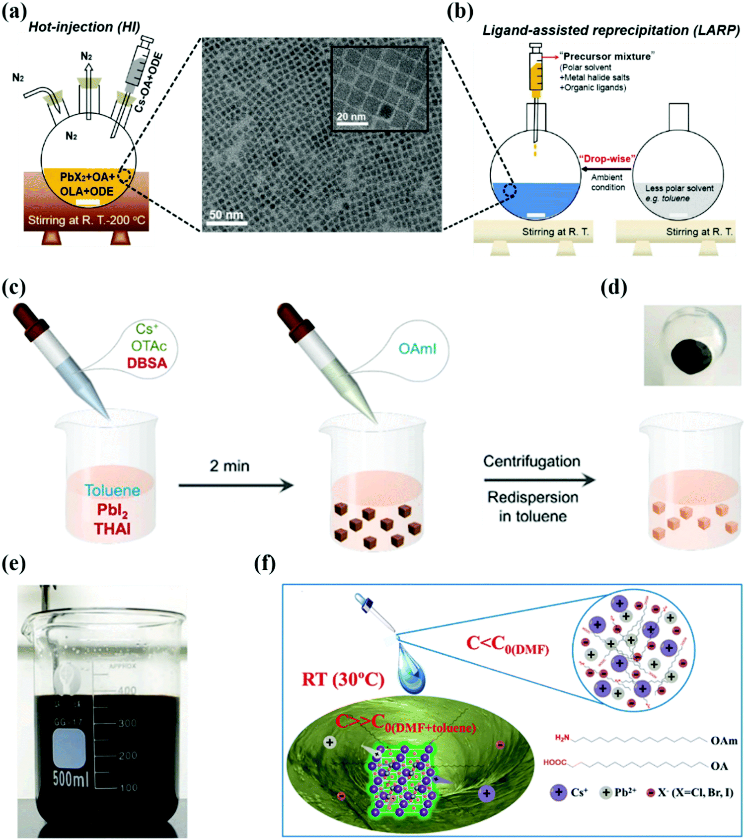 | ||
| Fig. 2 (a and b) Schematic representation of perovskite QDs by hot-injection and ligand-assisted reprecipitation methods (OA, OLA, and ODE represent oleic acid, oleylamine, and octadecene respectively and PbX2 [X = Cl, Br]), the as-synthesized CsPbI3 QDs with corresponding transmission electron microscopy (TEM) and high-resolution TEM images.101 (c) Schematic diagram of CsPbI3 QD synthesis using the ligand-mediated strategy (LMS). (d) Schematic representation of CsPbI3 QD precipitation after purification. (e) Photograph of the crude solution in the scaled-up synthesis of CsPbI3 NCs. (c–e) Ref. 100. (f) Schematic of RT synthesis of CsPbX3 QDs.90 | ||
Besides these improvements, the HI strategy is carried out under an inert gas atmosphere and at high temperatures, which directly influence the cost and output limit of the synthesis procedure. Second, the Cs oleate/iodide precursor synthesized in advance with a pre-heating temperature of 100 °C is indispensable to be injected into main reaction flask. So, it is difficult to control the large quantity of injecting agents at high temperatures during synthesis and acts as a bottleneck to produce QDs on a large scale. To tackle these issues, research teams developed alternative and straightforward routes of LT that can be employed in an open environment with affordable apparatus.41,90
Besides potential advantages, some shortcomings were associated with the LARP method: polar solvents quickly degrade PQDs, especially CsPbI3 QDs. The reason behind this fast degradation was the “solvent effect”, which produced a defective structure with a residual solvent and iodide vacancy on its surface layer.98,99 Additionally, these polar solvents (DMF and DMSO) have high boiling points and toxicity, which limit their applications in large scale production. Therefore, it is required to develop an alternative and facile strategy using nonpolar solvents to synthesize high luminance CsPbX3 QDs.41 In 2016, Pan et al. synthesized CsPbX3 QDs using a nonpolar solvent which exhibited a high PLQY of 50–85%. When these QDs are synthesized in toluene and xylene, a higher PLQY can be obtained relative to those of QDs in hexane and dichloromethane, which elaborates the significance of solvent engineering.95 The same strategy was extended to the synthesis of MAPbX3 QDs, where their high luminescence properties endow them with great potential for optoelectronic applications. Recently, Wang et al. synthesized CsPbI3 QDs at room temperature in nonpolar solvents by introducing the 4-dodecylben-zenesulfonic acid (DBSA) ligand, as shown in Fig. 2a–c. After adding the DBSA ligand and further increasing its ratio to octanoic acid (OTAc), the yellow color of the CsPbI3 QDs gradually changed into a brown-black color which indicates the desired form of QDs for optoelectronic applications. The reason behind these obvious changes is the synergistic effect of the DBSA ligand which suppresses the [PbX6]4− distortion and provides phase stability at room temperature. This facile synthetic route of CsPbI3 QDs is highly appropriate for their large scale production due to their high reaction yield of 1.3 g.100
3.2. Post-treatment of CsPbI3 QD
Despite the defect tolerance nature of CsPbI3 QDs, A, X surface vacancy defects are detrimental to the device's photoelectric performance. These defects arise from the lack of ligand bonding which leaves empty sites of intrinsic halides at the surface during synthesis.54,102 Furthermore, it was experimentally confirmed through nuclear magnetic resonance (NMR) results that R-NH3+ captured the A-site in the perovskite structure and connected with the X-site via hydrogen bonding.56 This defect was eliminated by using amine-based passivating materials (formamidinium iodide, phenethylammonium iodide). The low Jsc is due to residual OLA ligand on QDs surface even after methyl acetate washing, exchanged by formamidinium iodide (FAI) ligand and higher Jsc up to 15.246 mA cm−2, which correspondingly enhanced the device efficiency from 10.7% to 13.43%.103 Due to detrimental effects associated with FAI treatment, Kim and coworkers exchanged the OLA ligand with phenethylammonium iodide (PAEI) to improve the electronic coupling and moisture stability. Here PEA has an aromatic organic cation of large size, which can block the phase decomposition of the PQD structure caused by environmental factors. This conclusion can be deduced from the black color of the film, which was retained for fifteen days. Finally, PEAI treated QD solar cells (QDSCs) have shown the maximum performance of 14.1% with excellent stability and the PEAI post-treatment mechanism on resultant CsPbI3 QDs is shown in Fig. 3a.104 In 2019, we adopted CsAc salt for filling those vacancies which occurred from the detachment of additional (OAm)+ during the ligand exchange process. This modification enhanced the QD coupling and reduced the trap-assisted non-radiative recombination by filling these vacancies, which is shown in Fig. 3b.60 Afterwards, we reported the secondary amine (di-n-propylamine) treatment between the washing process of QD films and FAI post-treatment, providing efficient control over the surface ligand density, which is essential for balancing the charge transport and phase stability. Eventually, CsPbI3 QD solar cells exhibited improved charge transport with a high PCE approaching 15%.105 Quite recently, a novel GA matrix-capped CsPbI3 QD film was achieved by dipping the material in a guanidinium thiocyanate (GASCN) solution which helped in maintaining a cubic structure and increasing the QD coupling. The champion device exhibits a high reproducible PCE of 15.21%, which is shown in Fig. 3c.106 These strategies provide the future roadmap to exceed the Jsc of QD solar cells, enhancing the device performance and long-term stability. On the other hand, XPS analysis detected a non-stoichiometry ratio of ions, Cs:Pb:I (1:1:2), which led to the formation of X-site termination.57 This halide vacancy was filled by the OA ligand, but it does not provide colloidal integrity to the QD structure in terms of long-term storage. The reason behind this failure is weak bond formation, which occurred from the mismatch between the hard OA and soft Pb. In light of this mismatch, Nenon et al. offered softer carboxylate ligands (benzoate, difluoroacetate) which exhibit strong binding with the under-coordinated Pb2+ atom, yielding a trap free CsPbX3 QD.58 Shi and coworkers exhibited in situL-phenylalanine (L-PHE) strategies. This bifunctional ligand acts as an aromatic surfactant which can passivate both the cations and anions of the QD surface. Through this modification, they achieved a superb photovoltaic and LED performance. This result was supported by density functional theory (DFT), which shows a stronger bonding between the L-PHE and CsPbI3 QD surfaces relative to native ligands. This is visualized in Fig. 3d.107 In this process, by removing the long-chain native ligands which are involved in the QD purification and film preparation, degeneration of ions occurs, leaving behind defects on the surface.61,108 To address such problems, a single-step of ligand exchange was used by Jia et al. to eliminate defect occurrence during each layer of spin coating. They used amino acids as a dual passivating agent for cationic and anionic defects caused by the antisolvent immersion process. The absence of defects on the QD surface lessens non radiative recombination, leading to improved carrier mobility and device performance.109 Moreover, Khan et al. proposed a solid-state passivation mechanism for halide vacancies caused by purification and film fabrication processes. By using 4-mercaptopyridine (4-MP) as a bi-functional ligand, where anchoring position play significant role in ligand performance. As a result, solid QDs retained their cubic phase for 70 days under standard humidity conditions and at room temperature and achieved efficiency over 14%. In addition, this strategy also eliminates the time sensitive FAI treatment which has a negative impact on the perovskite QD crystal structure.110 Hence, rational post-treatment of either the as-prepared QD solution or the film provides an important way for the improvement and stability of CsPbI3 QDs.
 | ||
| Fig. 3 (a) Schematic representation of the post-treatment mechanism using PEAI on the resultant CsPbI3 QDs.104 (b) Schematic illustration of CsPbI3 QD film deposition and CsX post-treatment mechanism.60 (c) Schematic diagram of the ligand exchange process for the formation of GA-matrix-capped CsPbI3 QD solids by thermal annealing induced by guanidinium thiocyanate (GASCN).106 (d) Schematic illustration of the CsPbI3 QD surface and theoretically calculated adsorption energy of different ligands (OLA, OA and L-PHE) using DFT application on the pure CsPbI3 QD surface.107 | ||
3.3. PQD ink
As is known, the current fabrication process of CsPbI3 QD photovoltaics is mainly reliant on solid-state ligand exchange, which can be performed through repeated layer-by-layer cycles to achieve the desired thickness of the CsPbI3 QD absorber.106 Such a time-consuming and costly method is not a proficient way to fabricate photovoltaic devices having an active area greater than 800 cm2 on a commercial scale.111 To overcome this critical issue, solution-phase ligand exchange (SPLE) is an advanced and practical approach to realizing QD films on a large scale using one-step deposition with well-defined and repeatable thicknesses. QD inks can be coated directly onto a substrate with appropriate short ligands.112 Moreover, the precise and uniformly exchanged QD ink eases all the fabrication steps and thus provides a new avenue for optimizing the efficiency and stability of QD solar cells. In this perspective, PbS QDs achieved a well-established process of solution exchange, through which a relevant device PCE of over 12% was achieved.113 This fruitful progress has taken a decade of struggle to achieve PbS QD inks. In contrast, the solution exchange process of CsPbI3 QDs is not so simple and easy because it requires polar solvents to dissolve inorganic ligands, which can destroy the ionic structure of the perovskite.114,115 Quite recently, some research groups initiated work on the development of the SPLE process of CsPbX3 QDs. The relevant literature has shown that Zhang et al. produced dry CsPbX3 QDs by the SPLE process which exhibit a high PLQY and demonstrate good stability under an ambient atmosphere. This excellent job was achieved by using a thiol halide (SOCl2), which simultaneously removes the long native ligands and protects the QD surface with halide ions.116 Similarly, Wang demonstrated solution exchange of CsPbI3 QDs via inorganic (KI) ligands, where I− ions are used to treat vacancies that occurred during ligand substitution. At the same time, K+ promotes mechanical coupling in the light of a small radius. As a result, the device exhibited a maximum EQE of 23% with improved phase stability.117 Recently, our group successfully implemented CsPbI3 QD ink for photovoltaic applications. The short and functional ligands of phenylethyl ammonium (PEA+)/2-(4-fluorophenyl) and ethyl ammonium (FPEA+) effectively passivate the surface defects of CsPbI3 QDs and boost the device PCE up to 14.65% with excellent stability. This prolonged device stability is due to the hydrophobic nature of PEA+ and FPEA+, which increased the solid-state QD resistance against moisture.118 However, the current protocol of solution exchange is not mature like PbS or PbSe QDs because it mainly relies on short organic ligands. Therefore, we should add new ligands/multi-functional ligands which bind strongly with the surface of PQDs for sufficient protection during the solution exchange process.4. CsPbI3 PQD solar cells
4.1. Device architecture engineering
In this section, we focus on the PQD photovoltaic device operation principle and their device structure optimization. It is necessary to know the physics of the optoelectronic mechanism involved in the operation of QD solar cells, which directly affects the optical and electrical characteristics, separation and transport of charge carriers, their recombination mechanisms, and finally extract useful output power in an external circuit. The entire working process is strongly dependent on various materials used in each layer and their properties, and the overall configuration of the device, as shown in Fig. 4a. In this perspective, PQDs are a promising candidate to be used as a light-harvesting layer due to their appropriate tunable bandgap and effective generation of electron–hole (e–h) pairs. It is now mandatory to separate and collect sufficient holes and electrons precisely to avoid recombination in their corresponding hole and electron transport layers. In addition, the electrons are moved to the electron transport layer from the PQD absorber layer and then get accumulated at FTO. At the same moment, the holes are shifted to the hole transport layer and, at last, proceed to the metal electrode. Finally, the current passes through the external circuit by connecting the metal electrode and FTO. In addition, the research community has focused on the PCE of all types of solar cells to judge the performance under some standard test conditions. The PCE is obtained by calculating the maximum output power from the well-known current density–voltage characteristic (J–V) curve by considering the standard conditions for characterization of solar cells under global AM 1.5 spectrum with an input light intensity (Pin) of 100 mW cm−2.119,120 We can find the output power (PO) from the illuminated J–V characteristic curve in terms of Voc, Jsc, and fill factor (FF). Mathematically, the PCE can be expressed as:
where Vmax and Jmax represent the maximum voltage and current density at the maximum power, respectively.

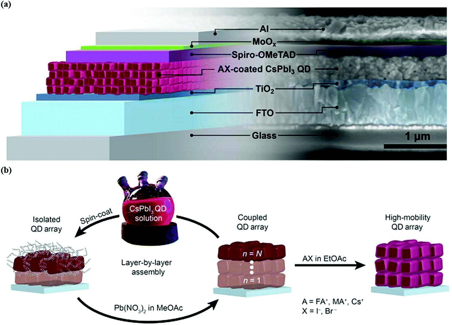 | ||
| Fig. 4 (a) Illustration of the working principle of QDSCs. (b) Growth of the CsPbI3 QD absorber layer via the spin coating process.103 | ||
Device structure optimization plays a vital role in boosting the performance of PQD solar cells after the surface chemistry modification. The PQD solar cell device is a multilayer structure consisting of a front layer, usually a transport conductive oxide (FTO, ITO), a PQD absorber layer between electron transport materials (TiO2, SnO2,),121,122 and a hole transport layer (Spiro-OMeTAD, PTB7, PTAA, P3HT)123 which helps in charge carrier separation and collection. There are mainly two types of device architectures that have been reported for QDSCs depending on the illumination side and current direction. These are called planar (N–i–P) conventional or (P–i–N) inverted. The simple layer-by-layer device architecture mechanism is presented in Fig. 4b. Despite high efficiency, the choice of hole-transporting materials (HTMs) is still not explored very well because the existing HTMs used in conventional structures face both stability issues and increased cost. For instance, Spiro-OMeTAD possess poor stability, and low hole mobility and conductivity in its pure form. However, a doping and oxidation mechanism can enhance their hole mobility, conductivity, and stability for its use in photovoltaics. For this reason, it is necessary to replace Spiro-OMeTAD with other organic or polymer-based HTMs such as PTAA and PTB7, both of which demonstrate good stability. In addition, these organic/polymer based HTMs cannot be used directly because they need a further purification mechanism, which increases the cost of the conventional structure. On the other hand, compact TiO2 is incompatible with ITO and a flexible substrate due to its preparation method at high temperatures.62 Therefore, the best alternative is the inverted N–i–P structure, which offers simple preparation techniques at relatively low temperatures, making it suitable for flexible and tandem devices.62,124Table 1 illustrates the recent progress of CsPbI3 PQD solar cells. For example, Tavakoli et al. effectively fabricated semitransparent inverted PQD solar cells. They achieved an extraordinary average visible transmittance up to 53%, suitable for window applications with a PCE of 6.8%.125 However, the HTM used in such a device was PTAA which exhibits a lower Voc. This can badly affect the overall performance of inverted solar cells due to indigent QD deposition on PTAA.126 Shivarudraiah et al. successfully prepared inorganic CsPbI3 PQD solar cells with an inverted device structure by utilizing the inorganic NiOx as an HTL having an insensitive nature in the solvent, achieving an enhanced PCE of up to 13%.127 Owing to these unique properties, it is essential to design and fabricate low-temperature processing, cost-effective, and efficient PQDs based on inverted solar cells in the future. Moreover, in QDSCs, it is practically feasible to use a bilayer or multi-layer deposition of PQDs as a light-harvesting layer, which forms a heterojunction-based device structure. For instance, Bian et al. systemically engineered a heterojunction structure containing a CsPbI3 QD layer on the top of the CsPbI2Br QD layer. This structure possesses a graded bandgap at the interface, effectively increasing charge collection as well as device efficiency (14.45%).128 These results revealed that PQDs could provide an ideal platform for fabricating different and multiple layer devices for photovoltaic applications.
| Device configuration | QD size (nm) | PCE (%) | J sc (mA cm−2) | FF (%) | V oc (V) | Year | Ref. |
|---|---|---|---|---|---|---|---|
| FTO/TiO2/α-CsPbI3 QDs/Spiro-OMeTAD/MoO3/Al | 9 | 10.77 | 13.47 | 65.0 | 1.23 | 2016 | 26 |
| FTO/TiO2/FAI treated-α-CsPbI3 QDs/Spiro-OMeTAD/MoO3/Al | 9 | 13.40 | 14.37 | 78.0 | 1.20 | 2017 | 103 |
| FTO/TiO2/μGR α-CsPbI3 QDs/PTAA/Au | 10 | 11.40 | 13.59 | 72.6 | 1.18 | 2018 | 129 |
| FTO/TiO2/α-CsPbI3 QDs/PTB7/MoO3/Ag | 8 | 12.55 | 12.4 | 80.0 | 1.27 | 2018 | 123 |
| FTO/TiO2/α-CsPbI3 QDs/Spiro-OMeTAD/Au | 9.8 | 11.87 | 16.98 | 67.2 | 1.04 | 2019 | 59 |
| FTO/TiO2/GeI2-α-CsPbI3 QDs/Spiro-OMeTAD/Au | 12 | 12.15 | 14.8 | 74.0 | 1.11 | 2019 | 130 |
| FTO/TiO2/α-CsPbI3 QDs/Spiro-OMeTAD/MoOx/Ag | 10 | 13.30 | 15.21 | 74.2 | 1.18 | 2019 | 131 |
| ITO/PTAA/α-CsPbI3 QDs/C60/BCP/Cu | — | 13.40 | 17.10 | 70.0 | 1.12 | 2019 | 132 |
| FTO/TiO2/α-CsPbI3 QDs/PTAA/MoOx/Ag | 9 | 14.10 | 14.96 | 75.6 | 1.24 | 2019 | 60 |
| FTO/TiO2/α-CsPbI3:Yb QDs/PTB7/MoOx/Ag | 10 | 13.12 | 14.2 | 74.0 | 1.25 | 2019 | 133 |
| FTO/TiO2/α-CsPbI3 QDs/Spiro-OMeTAD/Au | 9.1 | 14.32 | 17.80 | 75.8 | 1.06 | 2020 | 121 |
| FTO/TiO2/α-CsPbI3 QDs/PTAA/MoOx/Ag | 9 | 14.90 | 15.84 | 75.5 | 1.24 | 2020 | 105 |
| FTO/TiO2/α-CsPbI3 QDs/PTAA/MoO3/Ag | 10 | 14.10 | 15.3 | 74.8 | 1.23 | 2020 | 104 |
| FTO/TiO2/α-CsPbI3 QDs/PBDB-T/MoOx/Ag | 10 | 13.80 | 15.10 | 75 | 1.22 | 2020 | 134 |
| FTO/TiO2/α-CsPbI3 QDs/PTAA/MoOx/Ag | 9 | 14.65 | 15.38 | 74.7 | 1.27 | 2021 | 106 |
| ITO/SnO2/PCBM/α-CsPbI3 QDs/PTB7/MoOx/Ag | 10 | 15.10 | 15.2 | 78.0 | 1.26 | 2021 | 135 |
| ITO/SnO2/α-CsPbI3 QDs/Spiro-OMeTAD/Ag | 9 | 16.21 | 16.21 | 72.0 | 1.27 | 2021 | 136 |
| FTO/TiO2/F6TCNNQ dopped-CsPbI3 QDs/PTAA/MoOx/Ag | 9.6 | 15.29 | 17.12 | 71.4 | 1.25 | 2021 | 142 |
| FTO/TiO2/α-CsPbI3 QDs/PTAA/MoOx/Ag | 10 | 15.21 | 15.54 | 79.45 | 1.23 | 2021 | 146 |
4.2. The role of the CsPbI3 PQD layer
As we discussed above, the role of the absorber layer is crucial in determining the performance of the photovoltaic device. The material used as an absorber layer of solar cells depends on important parameters such as film thickness, bandgap, doping concentration, defects density, and operating temperature.136,137 Up to now, various conventional and solution processed sunlight absorbers have been reported. For instance, a dye molecule is used as an absorber in dye synthesized solar cells (DSSCs) to harvest sunlight. However, its short range of visible wavelength and liquid phase correlating with the bandgap and operating temperature parameters of the absorber layer limit the device performance as well as stability.138,139 Polymer absorbers are cheap, demonstrate a high absorption coefficient, and have a tunable bandgap by changing the length/functional group of the polymer. However, its intrinsic issues like low crystallinity and shorter diffusion length limit the carrier transportation, and finally yield low efficiency of polymer solar cells.140 In contrast to the above-mentioned absorber layers, perovskite materials, especially all-inorganic perovskites (CsPbI3 QDs), possess all basic characteristics of the absorber layer and exhibited a PCE of over 16% in a minimal time.141To utilize a CsPbI3 QD film as an absorber layer in a photovoltaic material, it would be a wise strategy to increase the thickness of the absorber layer (∼1 μm). This is because it has a defect free nature which helps in optimizing the photon absorption while demonstrating impressive extraction of photogenerated carriers and their transportation. In this perspective, Zhang et al. successfully developed a thick-film of over 1 μm of CsPbI3 QDSCs which consist of a P/N homojunction of QD arrays. They used 2,2′-(perfluoronaphthalene-2,6 diylidene)dimalononitrile (F6TCNNQ) for developing p-type CsPbI3 QDs by a charge transfer doping strategy and established an internal P–N junction with n-type QDs. The wide depletion region of the novel device relative to that of the pristine QDs helped in ensuring an effective extraction of photogenerated carriers, their transportation, and lower carrier recombination. These effects help in obtaining a high PCE of 15.29%. However, the novel device efficiency decreased to 12.28% at 1.2 μm thickness.142 This thickness restricts the carrier's diffusion length and recombination before reaching the corresponding electrodes.143 In the light of these defects (A/X sites), which occurred at the CsPbI3 QD surface, can be passivated by ammonium cation or same halide. Along this line, FAI, PAEI, and guanidinium thiocyanate(GASCN) have proved to be the best ligands for refilling the A-site and halide vacancies to form an optimized surface of CsPbI3 QDs.103,104,106 There are other types of ligands which can be used to passivate both the A/X sites. For example, Shi et al. introduced L-phenylalanine via an in situ passivation process for cation and ion passivation at the surface of CsPbI3 QDs.107 Some Lewis base ligands were also implemented for passivation of under coordinate sites of Pb2+ and achieved excellent device performance and stability. The Lewis base molecules contain a lone pair of electrons on nitrogen (N), sulphur (S), oxygen (O), or phosphorus (P) atoms, which enable them to form bonds with the electron deficit counterpart (Pb2+) by donating these electrons.144 Bi et al. introduced 2-aminoethanethiol (2-AET) for passivation of Pb2+ ions on the surface of solid CsPbI3 QDs, which have a high binding affinity toward Pb2+.145 The strong interaction between P and Pb of chalcogenide QDs helped in passivating Pb2+ ions of CsPbI3 QDs and improved the device performance up to 15.21% by introducing an organic triphenyl phosphite (TPPI) ligand.146Fig. 5 describes different types of ligands used for the passivation of perovskite NCs. After well furnishing of PQDs, we briefly discuss other aspects of the absorber layer of CsPbI3 QDs. For instance, we introduce mixed PQDs for optimization of the bandgap of the absorber layer, which increases the harvesting of sunlight and carrier transportation toward corresponding electrodes. Zhao et al. demonstrated the tunability of a wider bandgap of CsPbI3 QDs by Cs0.25FA0.75PbI3 QD heterojunctions that enable rational design of a charge separating interface within an absorber layer and achieved a PCE of 16.6%.43 Non-radiative recombination arises from undesired energy levels in the perovskite absorber with the corresponding transporting layer. This mismatch of energy levels can suppress the induction of the desired size of PQDs. Wang et al. established a beach-chair shape for CsPbI3 solar cells, which not only increased the charge transport but also decreased the recombination loss during the carrier extraction process.147
 | ||
| Fig. 5 Schematic illustration of various ligands used for the passivation of the PQD absorber layer.54 | ||
4.3. The role of the interface
As QDs have a large defect density at its surface relative to a bulk film, their defect density increases during colloidal transformation into solid QDs.148 These defects are located at the interface between the QDs and carrier transporting layers of the device, acting as charge trapping centers which negatively affect the device performance and stability.149 The degree of complexity in the device increases with the number of interfaces that directly impact the device performance and stability. This phenomenon is truly observed in perovskite-based multijunction structures such as tandem devices.150 To address this interfacial problem, it is necessary to diminish interfacial nonradiative recombination losses via interface molecular passivation, which occur from interface defects and imperfect energy level alignments.151 Hu et al. adopted a hybrid interfacial strategy (HIS) for the passivation of under coordinated Pb2+ ions on the CsPbI3 QD surface. The phenyl-C61-butyric acid methyl ester (PCBM) molecule bonds with the Pb2+ ion via its carboxyl functional group. It produces an exciton cascade between the PQD absorber layer and the ETL of the device, which is shown in Fig. 6a. Furthermore, the champion device retained its approximate performance for 14 days in a dry-air glovebox, demonstrating HI's role in device stability.135 In addition to the front interface, the difference in surface energy between the QD absorber and conventional HTLs (PTAA, Spiro-OMeTAD) obstructs the photo-induced holes, adversely affecting the device performance. Ji et al. introduced a bulk heterojunction of polymer and PQDs at the bottom interface, which enhances charge transfer and lessens interfacial recombination of photo carriers, improving the device performance. This is presented in Fig. 6b.134 In the same context, Zhang et al. tailored interfacial carrier dynamics using poly(acrylic acid)-block-polystyrene (PAA-b-PS) capped-CsPbBrxI3−x QDs at the MAPbI3/HTL interface. The PS-ligated CsPbBrxI3−x QDs at the perovskite absorber layer/HTL reduced the surface trap states and achieved a favorable band alignment which led to a long mobile carrier life time and high charge collection efficiency. Subsequently, the PCE of CsPbBrxI3−x incorporated devices approached 19.21% with excellent stability.152 Despite one side passivation, the synergistic effect of double sided passivation is more worthwhile because the QD layer is a sandwich-like wafer biscuit between the charge carrier transporting layers. Both the upper and bottom surface of the QD layer have interface problems that can influence carrier behavior inside the device. Thus, Xu et al. introduced organic molecules layers (P![[double bond, length as m-dash]](https://www.rsc.org/images/entities/char_e001.gif) O, SO, and CO) between the top and bottom interface regions of the CsPbX3 QD device to reduce the defect density and interfacial non-radiative recombination. Among the various functional groups, strong interaction between Pb and the phosphorus oxygen group suppressed defect regeneration leading to better device stability. The decrease in defect density was confirmed by transient photocurrent methods like SCLC and DLCP.149 To extend light harvesting, the absorber layer of the device can be constructed using different QDs such as CsPbI3 and FAPbI3 QDs (Eg = 1.5 eV). Li and coworkers took advantage of this idea and successfully fabricated a solar cell with a bilayer structure (CsPbI3QDs/FAPbI3 QDs) with the addition of graded composition by thermal annealing, which is shown in Fig. 6c. The net device demonstrated a high photo induced current density (17.26 mA cm−2) with leading efficiency (15.6%). Furthermore, they found high phase stability in the graded structure compared with the parent structure (CsPbI3 QDs) due to the large size of organic (FA+) cations.153 From these results, we concluded on the qualitative importance of the interface, which guides us to modify the interfacial properties for achieving both enhanced PCE and stability of the photovoltaic device.
O, SO, and CO) between the top and bottom interface regions of the CsPbX3 QD device to reduce the defect density and interfacial non-radiative recombination. Among the various functional groups, strong interaction between Pb and the phosphorus oxygen group suppressed defect regeneration leading to better device stability. The decrease in defect density was confirmed by transient photocurrent methods like SCLC and DLCP.149 To extend light harvesting, the absorber layer of the device can be constructed using different QDs such as CsPbI3 and FAPbI3 QDs (Eg = 1.5 eV). Li and coworkers took advantage of this idea and successfully fabricated a solar cell with a bilayer structure (CsPbI3QDs/FAPbI3 QDs) with the addition of graded composition by thermal annealing, which is shown in Fig. 6c. The net device demonstrated a high photo induced current density (17.26 mA cm−2) with leading efficiency (15.6%). Furthermore, they found high phase stability in the graded structure compared with the parent structure (CsPbI3 QDs) due to the large size of organic (FA+) cations.153 From these results, we concluded on the qualitative importance of the interface, which guides us to modify the interfacial properties for achieving both enhanced PCE and stability of the photovoltaic device.
 | ||
| Fig. 6 (a) Schematic illustration of the device structure and energy level of pristine and an optimized device by utilizing a PCBM modified layer between the SnO2 and CsPbI3 QD layer.135 (b) Schematic diagram of the device structure and energy level of PQD solar cells with polymer-QD BHJ connecting layers.134 (c) Schematic representation of the CsPbI3 QD and FAPbI3 QD bilayer structure with an optimized band alignment diagram.135,153 | ||
4.4. Long-term stability
It is known that the colloidal state of α-CsPbI3 QDs, unlike its bulk counterpart, retains its black phase stability at room temperature.26 The variant of this property motivated further exploration to avoid or minimize lattice distortion during the purification process of CQDs. Sun et al. reported the influence of polar solvents on the stability of CsPbI3 QDs.154 CsPbI3 QDs were dispersed in ethanol and stored in an ambient environment. The dark-red color slowly changed, indicating a phase transformation of the cubic phase into the orthorhombic phase. AC-STEM images were analyzed to visualize the distortion induced by polar solvents, which revealed structure evolution on an atomic scale. These results are shown in Fig. 7a–d. The reason behind this failure is the high ionic and dynamic interaction of ligands and the QD surface, which can be mitigated by using low polar anti solvents.26,155,167 Beyond polar solvents, it is also revealed that solid CsPbI3 QDs are also incapable of retaining their cubic phase due to ligand detachment which imparts tensile surface strain. With the passage of time, the film color changed into a yellow liquid, which coincided with the changes in the UV-vis absorption spectra and XRD results. These are shown in Fig. 7e and f.110 So, it is established that the crystal structure of solid CsPbI3 PQDs was not stable enough and got worse by the additional defects during the imperfect ligand exchange process of oleate for acetate.104,156 These additional defects were treated with a short chain ligand (4-MP) which bound strongly with the CsPbI3 QD surface. As a result, solid CsPbI3 QD films extended the cubic phase stability which is obvious from the absorption spectra and XRD analysis, which is shown in Fig. 7e and f.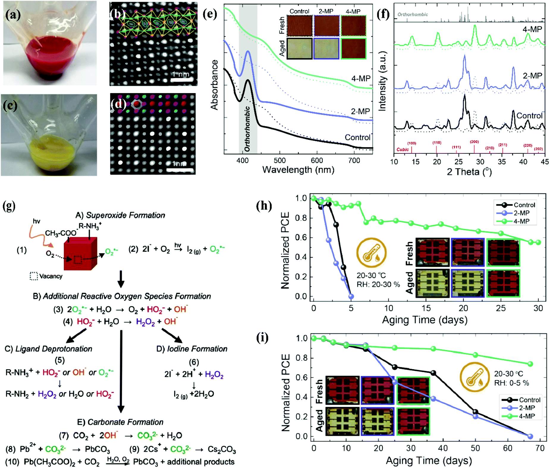 | ||
| Fig. 7 (a and b) Digital images of the reaction flask without an ice bath and with ice bath cooling after injecting Cs precursor at a reaction temperature of 180 °C. (c and d) Magnified view of high-angle annular dark field (HAADF) images of the pure cubic CsPbI3 and ethanol-absorbed CsPbI3 nanocrystals.167 (e and f) Schematic illustration of the phase change of solid QD films in an ambient environment supported by UV-vis absorption spectra and XRD results.110 (g) Photo-oxidation strategy of CsPbI3 QDs involving different processes, which are labelled as A, B, C, D and E, respectively.158 (h and i) Stability of CsPbI3 QD solar cells under an ambient environment after post-treatment of 2-MP and 4-MP as well as inserted images of fresh and aged solar cell devices.110 | ||
To evaluate the influence of external factors (heat, U-V light, water, oxygen and temperature) on the device performance and stability.62,157 It is ascertained from the literature that under-coordinated sites of CsPbI3 NCs were filled by molecular oxygen (O2−), which results in superoxide (O2−) formation. Fig. 7g represents the ways out of superoxide (O2−) formation at the CsPbI3 QD surface. First, the photoinduced electron was involved in the superoxide (O2−) formation. Second, the light-induced reaction of the I− ligand and the molecular oxygen resulted in I2 and O2− formation. Once the superoxide (O2−) matured, it then reacted with water and other reactive oxygen species (ROS) like hydroxide (OH−), perhydroxyl (HO2−), and hydrogen peroxide (H2O2), which triggered cluster chains of self-propagating reactions.158 As a result, ligand deprotonation occurred, where R-NH+3 acquired the R-NH2 form with additional products of water/ROS and left behind under-coordinated sites of I− at the surface.159,160 Second, H2O2 and free species (H+) of deprotonated R-NH+3 reacted with I−, yielding I2 formation and under-coordinated sites of Pb2+. Such a new channel of emerging vacancies speeds up the degradation process of solid CsPbI3 QDs, which further fluctuates the device performance and stability.158,161 Third, the superoxide (O2−) reacted with CO2 and produced carbonate (CO32−) and water. Then CO32− produced PbCO3 and CsCO3 by reaction with the under-coordinated sites of Pb2+ and Cs+.162 Eventually, it is confirmed that these under-coordinated sites are a key region of PQDs that cause the degradation of the perovskite structure. In addition, Spiro-OMeTAD is mostly used as the device HTL which further deteriorates the operational stability of the perovskite solar cells at high temperatures. The volatile nature of doping components provides a new avenue for the diffusion of gold/silver ions toward the perovskite film, where they react with a halogen of the perovskite. As a consequence, the device faced degradation, poor reproducibility, and high hysteresis in the J–V curve.123,163 To mitigate the degradation process of the CsPbX3 structure, different strategies are applicable such as compositional engineering, defect passivation, and unconventional strategies (e.g. star-like tri-block copolymers which act as nanoreactors and help in encapsulation of the device).44,46,164,165 In this new approach, Yoon et al. introduced amphiphilic star-like di-block copolymers consisting of a hydrophilic inner PAA and a hydrophobic outer PS block of varying lengths. Interestingly, the bond formation between this outer PS and inner PAA is covalent, ensuring a friendly and stable CsPbX3 QD surface capped with a PS block. This showed superior colloidal stability in nonpolar solvents and minimized QD aggregation.166
Furthermore, the encapsulation can eliminate the interaction of molecular oxygen, water, and ROS with the perovskite QD film. Still, a question arises on the decomposition and agglomeration of PQDs with device operation under continuous illumination. Therefore, compositional engineering and defect passivation is a vital strategy for improving the crystal lattice and ensuring a defect free surface. This helps in achieving long-term stability. The state-of-art stability of the CsPbI3 QD device via ligand passivation is shown in Fig. 7h and i.
4.5. Chemical composition engineering
Composition engineering is a promising strategy to stabilize the crystal structure and optoelectronic properties of PQDs.168,169 Due to the ionic nature of perovskites, the doping process of PQDs relative to chalcogenide QDs is much simpler.170 During the doping/alloying process, GTF (τ) has gained significant importance in predicting the perovskite crystal stability. According to equation (1.1) of tolerance factor, the stability of the crystal lattice can be improved by increasing the radius of the A-site or decreasing the radius of the B/X site.171 Besides GTF (τ) formulation, the octahedral factor (μ) is also a considerable evaluation criterion for composition engineering.172 The influence of doping/alloying at different sites of the perovskite structure will be discussed briefly in the following sessions.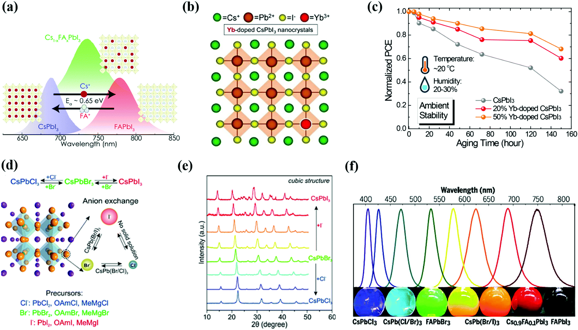 | ||
| Fig. 8 (a) Schematic representation of doping of FA cations in the CsPbI3 QD structure and developed Cs1−xFAxI3 structure.177 (b and c) Schematic illustration of Yb doping in CsPbI3 QDs and improvement in the device ambient stability on pristine CsPbI3 QDs and with 20% and 50% Yb doping without encapsulation.133 (d–f) The exchange of halide (X) composition and developed different structures of PQDs which are validated by XRD results and wavelength shift.170,186 | ||
4.6. Tandem and flexible solar cells
Single-junction perovskite solar cells achieved an optimum efficiency of 25.5%, where the maximum theoretical limit of the SC is 33.7%.10 Therefore, different strategies are employed to push the efficiency past this theoretical limit at reasonable costs using techniques such as using a defect-free absorber layer, MEG, and tandem devices. The working principle of a tandem device is based on a combination of two sub-cells that mainly work to maximize the photon absorption and reduce thermal losses. In a tandem structure, the perovskite layer is used as a top sub-cell to harvest high energy photons while a silicon/polymer material is used at the bottom for absorbing low energy photons. This architecture is shown in Fig. 9a.12 Besides efficiency, other factors like production cost are also critical for choosing the tandem device. Therefore, the broadband tunability of the perovskite inspired the concept of an all-perovskite tandem, which extended the general use of third-generation solar cells. In 2015, for the first time, the tandem structure of perovskite/perovskite solar cells was established by Heo et al. and achieved only 10.4% PCE.189 This reason behind this low efficiency is the small value of Jsc (10 mA cm−2) which stems from the mismatch of the bandgap of the top (2.25 eV) and bottom (1.55 eV) subcells.190 To overcome this intrinsic issue, Sn doping was introduced in the structure of MAPbI3 and achieved 1.22 eV bandgap for the bottom cell.191 For the top cell, the ideal band gap has the value of 1.75–1.85 eV, which directly aligns with that of all-inorganic CsPbI3 NCs (1.75 eV)26,190 Very recently, Zhang successfully prepared CsPbI3 QD inks by a solution exchange process, which prevented the recombination and protected the bottom layer of the tandem device during deposition.118 Additionally, the optical absorption of CsPbI3 QDs can be tuned by the doping of A/B/X elements, which allows PbS QD sub-cells for all-QD tandem solar cells.101 Perovskite thin-films emerged as the top sub-cell in Si/perovskite tandem devices and achieved a high PCE of 29.15%.192 So, PQDs could influence the fabrication process of the Si/PQD tandem device, resulting in low cost of the product in the energy market. That is why PQDs can provide the desired platform for acquiring high-performance tandem devices with diverse material combinations. | ||
| Fig. 9 (a) Schematic diagram of PQD based tandem solar cells.101 (b) PCE and stability comparison of flexible QDs and thin-film solar cells.135 (c–e) Schematic illustration of SEM images with investigation of cracks in PQDs and thin-film solar cells as a function of bending cycles.135 | ||
With technology development, solar cells have received more and more attention for their unique features including flexibility, portability, and light weight. As compared to rigid solar cells (silicon and GaAs), solution-processed solar cells (perovskites, polymers, and chalcogenide QDs) offer a unique opportunity for manufacturing flexible devices.193 For solar cells, high efficiency is the significant advantage of perovskites over other alternatives. In such context, MAPbI3 accomplished an 18.1% efficiency on a flexible substrate, though still lower than silicon performance.194 To improve the efficiency of the flexible device, MA can be substituted by FA for a broader absorption and achieved 20.1%.195,196 Unfortunately, the device cracks and delaminates during the high level of cyclic-bending fatigue test. In contrast, QDs show better mechanical flexibility due to the reduction of grain boundary dimensionality to the nanoscale. The utmost advantage of QDs is their deposition at room temperature, which is beneficial for flexible and stretchable devices. CsPbI3 QDs have also been utilized on flexible substrates and proved to be a prime candidate. For instance, Hu et al. demonstrated flexible QDSCs based on a hybrid interfacial structure and achieved a 12.3% PCE with high mechanical stability. This result is presented in Fig. 9b.135 To compare mechanical endurance, research groups conducted cyclic-bending fatigue tests for different solar cells like CbPbI3 QDs, CsPbI2Br, and Cs0.05MA0.85MA0.1PbI2.55Br0.45 thin films with 1000 bending cycles. They found no cracks/distortions in the morphology of CsPbI3 QD solar cells which appear in the thin film even after only 100 bending cycles. The same effect was investigated for the perovskite thin film which produced enormous cracks and spreading after 1000 bending cycles. This is depicted in Fig. 9c–e. All these findings proved that it is possible to design low-weight QDSCs because QDs possess superior compatibility with the flexible substrate due to the room temperature solution fabrication process and can be further explored in various optoelectronic applications.
5. Challenges and perspectives
CsPbI3 QDs have emerged as a promising candidate for photovoltaic applications since the pioneering work in 2016.26 In the past 5 years, CsPbI3 based QDs hold the highest PCE of 16.6% among all types of QD solar cells. The credit goes to attractive features like high defect tolerance, optimum band gap among all-inorganic perovskite QDs, and high carrier mobility.45 However, as shown in Fig. 10, there are severe problems such as soft ionic nature, lead (Pb) toxicity, and low efficiency at large-scale fabrication. These bottlenecks must be tackled prior to launching at a commercial scale.3,197 Therefore, we briefly highlight these core issues and provide a guideline for further device performance and stability improvements. The soft ionic nature of CsPbI3 QDs leads to fast formation kinetics which make it difficult to examine their nucleation and growth stages. To maintain the cubic phase, CsPbI3 QDs should be purified rapidly because excess ligands in the crude reaction promote the transformation of CsPbI3 NCs into Cs4PbI6.198,199 The purification process of CsPbI3 NCs has been largely restricted to a medium level anti-solvent such as methyl acetate and ethyl acetate due to their soft ionic nature. More common anti-solvents like acetone, ethanol, and isopropanol would corrode the crystal structure which leads to the instability of perovskite QDs.36 Furthermore, the ligand exchange process is a crucial step for NCs in optoelectronic devices to increase the inner coupling of QDs, leading to an improved current density of the device. To date, the solid-state exchange method has been the general protocol of ligand exchange of CsPbI3 QDs. Here, the timing of the ligand exchange is a very important factor for the complete removal of long-chain ligands and for avoiding QD agglomeration. Second, the highly dynamic interaction of the surface ligands and PQDs can cause fast desorption of the native ligand, which further complicates the time evaluation factor of ligand exchange which in turn triggers additional defects on the PQD surface. Once the superoxide gets access to these vulnerable sites, the structure collapses by propagating chain reactions of the superoxide and ROS.158 These flaws and surface imperfections can be treated using different strategies to achieve long-term stability.46,54,149 However, the PCE and stability of CsPbI3 QDs are unacceptable for researchers on comparing with counterpart solar cells at the commercial level. Second, all Pb-based perovskite QDs are a class of materials for photovoltaic applications and are expected to exceed the efficiency of the world-leading solar cells (CdTe, Si).43,200 However, a major concern is Pb toxicity that can be neurotoxic, immunotoxic, and nephrotoxic to the human body. So, the safety of human health and environmental protection should be the prerequisite for the installation of perovskite solar panels on a commercial scale.201 To address the Pb toxicity issue, Pb can be substituted with Sn2+ and Ge2+, which share the same electronic configuration as Pb. Unfortunately, Sn2+ is not stable and easily oxidizes to Sn4+ and the same behavior was observed in the Ge case.202 The health report card has shown more concern about the harmfulness of SnI2 relative to Pb poisoning induced by PbI2.203 Therefore, it is a very crucial and challenging aspect of perovskite structure to intact their optoelectronic properties while pursuing the stability and toxicity of Pb. The PCE of CsPbI3 QDSCs exceeds 16%. However, it still lags behind that of the bulk perovskite (>25%).45,49 This deficiency was caused by a wider bandgap of CsPbI3 QDs relative to MA-perovskites and high defect density at the QD surface which does not allow us to enlarge the film size and thickness.147,148 Therefore, we suggest some new directions to grip the current ongoing problems of CsPbI3 QDs and exceed efficiency over 20% for the device based on a single-junction structure.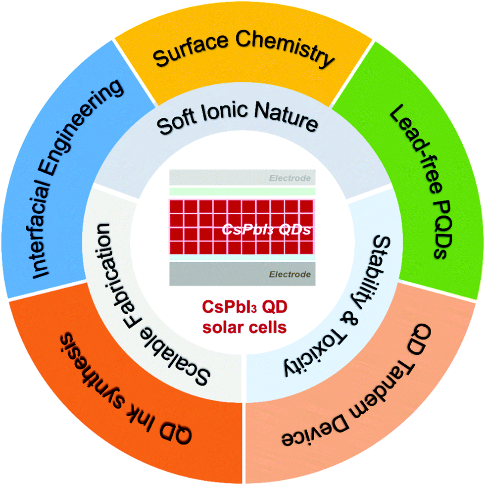 | ||
| Fig. 10 Challenges and prospects in CsPbI3 QD solar cells. | ||
In order to find an effective way for solving the intrinsic problems associated with soft ionic nature, the current ongoing binary approach of HI was carried out, which reproduced low yields of CsPbI3 QDs relative to chalcogenide QDs, the scale-up of which is essential for large-scale production. Therefore, we suggest a ternary precursor approach for CsPbI3 QDs and optimize it for CsPbI2.5Br0.5 QD synthesis to further strengthen the perovskite structure. However, the aggregation of PQDs during the purification process could be minimized by modifying the polarity of anti-solvents combined with different polarity anti-solvents.204 In light of device performance and stability, we explore short types of bifunctional ligands that bind strongly with A/X vacancies of CsPbX3 QDs with lower insulating structures for smooth transfer of charge carriers. Furthermore, we establish the optimum solution exchange process for robust passivation of CsPbX3 QD surface defects and avoiding the interfacial defects which arise from the layer-by-layer process of solid-state ligand exchange. Then, we can easily align the absorber bandgap with the corresponding layers of electron and hole transformers. These strategies are promising ideas for improvement in device performance and its state-of-art stability.
Pb-based PQDs dominate over lead-free PQDs, because of the high PLQY due to the crucial role of Pb2+ orbitals, which determine the VBM and CBM. On the other side, the substituting species added trap states between the VBM and CBM which coincide with its low PLQY. Therefore, it will be a better strategy to reduce the ratio of Pb by partial replacement of a metal cation (Mn, Zn, and Ni).46 In this regard, some double perovskite QDs were synthesized to mitigate the toxicity and stability issue of Pb-based QDs. For instance, Cs2AgBiBr6/Cs2AgBiCl6 QDs exhibit high air stability and are proposed as ideal candidates for photovoltaic applications, but their indirect bandgap causes low PL emissions and a low PCE of 2.2%.205 Later, Cs2AgInX6 QDs/Mn-doped Cs2AgInX6 QDs emerged as an alternative candidate with a direct bandgap, demonstrating good air stability and white PL emissions with a PLQY of 16%.206
The wider and tunable bandgap of CsPbI3 QDs makes them a promising candidate for the top sub-cell of tandem devices. Moreover, PQDs can be deposited at room temperature which added a feasible feature of flexibility as well as protected the morphology of the bottom film. Therefore, we believe that CsPbI3 QDs could combine with smaller bandgap QDs/polymers to fabricate tandem structures with flexible features which attract more attention of researchers for commercial applications such as wearable electronic devices and roll-to-roll roof panels.
Most high-efficiency CsPbI3 PQD devices are based on a small active area (<1 cm2), achieved in a controlled environment through a spin coating technique. For commercialization of CsPbX3 QD solar cells, large-scale fabrication is necessary. These processes should use techniques which are of low cost, feasible for large area, and have excellent reproducibility. In such a context, drop-casting and spin coating techniques are unfavorable for large-scale production. Some new techniques like blade-coating and spray coating are much more favorable for scale-up and large-scale fabrication. Right now, it is still a challenging task to fabricate devices at a large scale due to the failure of uniform and dense film deposition. However, non-radiative recombination of the rough film will be suppressed by improving deposition techniques which provide the way towards large-scale preparation of the device.
Conflicts of interest
There are no conflicts to declare.Acknowledgements
This work was supported by the National Key Research and Development Program of China (No. 2019YFE0108600), the National Natural Science Foundation of China (No. 52073198), the Natural Science Foundation of Jiangsu Province (BK20211598), the Science and Technology Program of Jiangsu Province (No. BZ2020011), the China Postdoctoral Science Foundation (Grant No. 2021T140495), and the “111” project, Collaborative Innovation Center of Suzhou Nano Science and Technology, Soochow University.References
- S. Shao and M. A. Loi, Adv. Mater. Interfaces, 2020, 7, 1901469 CrossRef CAS.
- N. Ameli and D. M. Kammen, Energy Sustainable Dev., 2014, 19, 130–137 CrossRef.
- J. Yuan, A. Hazarika, Q. Zhao, X. Ling, T. Moot, W. Ma and J. M. Luther, Joule, 2020, 4, 1160–1185 CrossRef CAS.
- N. S. Lewis, Science, 2007, 315, 798–801 CrossRef CAS PubMed.
- Q. Tai, K.-C. Tang and F. Yan, Energy Environ. Sci., 2019, 12, 2375–2405 RSC.
- H. Li, F. Li, Z. Shen, S.-T. Han, J. Chen, C. Dong, C. Chen, Y. Zhou and M. Wang, Nano Today, 2021, 37, 101062 CrossRef CAS.
- Z. Ning, X. Gong, R. Comin, G. Walters, F. Fan, O. Voznyy, E. Yassitepe, A. Buin, S. Hoogland and E. H. Sargent, Nature, 2015, 523, 324–328 CrossRef CAS PubMed.
- A. Kojima, K. Teshima, Y. Shirai and T. Miyasaka, J. Am. Chem. Soc., 2009, 131, 6050–6051 CrossRef CAS PubMed.
- H.-S. Kim, C.-R. Lee, J.-H. Im, K.-B. Lee, T. Moehl, A. Marchioro, S.-J. Moon, R. Humphry-Baker, J.-H. Yum and J. E. Moser, Sci. Rep., 2012, 2, 519 CrossRef PubMed.
- R. Wang, T. Huang, J. Xue, J. Tong, K. Zhu and Y. Yang, Nat. Photonics, 2021, 15, 411–425 CrossRef CAS.
- S. I. Seok and T.-F. Guo, MRS Bull., 2020, 45, 427–430 CrossRef CAS.
- M. Anaya, G. Lozano, M. E. Calvo and H. Míguez, Joule, 2017, 1, 769–793 CrossRef CAS.
- J. H. Noh, S. H. Im, J. H. Heo, T. N. Mandal and S. I. Seok, Nano Lett., 2013, 13, 1764–1769 CrossRef CAS PubMed.
- S. Brittman, G. W. P. Adhyaksa and E. C. Garnett, MRS Commun., 2015, 5, 7–26 CrossRef CAS PubMed.
- B. Conings, J. Drijkoningen, N. Gauquelin, A. Babayigit, J. D'Haen, L. D'Olieslaeger, A. Ethirajan, J. Verbeeck, J. Manca and E. Mosconi, Adv. Energy Mater., 2015, 5, 1500477 CrossRef.
- E. J. Juarez-Perez, Z. Hawash, S. R. Raga, L. K. Ono and Y. Qi, Energy Environ. Sci., 2016, 9, 3406–3410 RSC.
- J. Liang, C. Wang, Y. Wang, Z. Xu, Z. Lu, Y. Ma, H. Zhu, Y. Hu, C. Xiao and X. Yi, J. Am. Chem. Soc., 2016, 138, 15829–15832 CrossRef CAS PubMed.
- C. Liu, W. Li, C. Zhang, Y. Ma, J. Fan and Y. Mai, J. Am. Chem. Soc., 2018, 140, 3825–3828 CrossRef CAS PubMed.
- J. Deng, J. Li, Z. Yang and M. Wang, J. Mater. Chem. C, 2019, 7, 12415–12440 RSC.
- Y. Hu, F. Bai, X. Liu, Q. Ji, X. Miao, T. Qiu and S. Zhang, ACS Energy Lett., 2017, 2, 2219–2227 CrossRef CAS.
- P. Wang, X. Zhang, Y. Zhou, Q. Jiang, Q. Ye, Z. Chu, X. Li, X. Yang, Z. Yin and J. You, Nat. Commun., 2018, 9, 2225 CrossRef PubMed.
- Q. Wang, X. Zheng, Y. Deng, J. Zhao, Z. Chen and J. Huang, Joule, 2017, 1, 371–382 CrossRef CAS.
- W. Ke, I. Spanopoulos, C. C. Stoumpos and M. G. Kanatzidis, Nat. Commun., 2018, 9, 4785 CrossRef PubMed.
- Y. Wang, T. Zhang, M. Kan and Y. Zhao, J. Am. Chem. Soc., 2018, 140, 12345–12348 CrossRef CAS PubMed.
- L. Wu, K. Chen, W. Huang, Z. Lin, J. Zhao, X. Jiang, Y. Ge, F. Zhang, Q. Xiao and Z. Guo, Adv. Opt. Mater., 2018, 6, 1800400 CrossRef.
- A. Swarnkar, A. R. Marshall, E. M. Sanehira, B. D. Chernomordik, D. T. Moore, J. A. Christians, T. Chakrabarti and J. M. Luther, Science, 2016, 354, 92–95 CrossRef CAS PubMed.
- L. Protesescu, S. Yakunin, M. I. Bodnarchuk, F. Krieg, R. Caputo, C. H. Hendon, R. X. Yang, A. Walsh and M. V. Kovalenko, Nano Lett., 2015, 15, 3692–3696 CrossRef CAS PubMed.
- Q. Zhao, A. Hazarika, L. T. Schelhas, J. Liu, E. A. Gaulding, G. Li, M. Zhang, M. F. Toney, P. C. Sercel and J. M. Luther, ACS Energy Lett., 2019, 5, 238–247 CrossRef.
- R. D. Harris, S. Bettis Homan, M. Kodaimati, C. He, A. B. Nepomnyashchii, N. K. Swenson, S. Lian, R. Calzada and E. A. Weiss, Chem. Rev., 2016, 116, 12865–12919 CrossRef CAS PubMed.
- L. Duan, L. Hu, X. Guan, C. H. Lin, D. Chu, S. Huang, X. Liu, J. Yuan and T. Wu, Adv. Energy Mater., 2021, 11, 2100354 CrossRef CAS.
- Y. Zhang, G. Wu, F. Liu, C. Ding, Z. Zou and Q. Shen, Chem. Soc. Rev., 2020, 49, 49–84 RSC.
- O. E. Semonin, J. M. Luther, S. Choi, H.-Y. Chen, J. Gao, A. J. Nozik and M. C. Beard, Science, 2011, 334, 1530–1533 CrossRef CAS PubMed.
- A. R. Kirmani, J. M. Luther, M. Abolhasani and A. Amassian, ACS Energy Lett., 2020, 5, 3069–3100 CrossRef CAS.
- A. P. Alivisatos, J. Phys. Chem., 1996, 100, 13226–13239 CrossRef CAS.
- J. Owen, Science, 2015, 347, 615–616 CrossRef CAS PubMed.
- K. Chen, C. Wang, Z. Peng, K. Qi, Z. Guo, Y. Zhang and H. Zhang, Coord. Chem. Rev., 2020, 418, 213333 CrossRef CAS.
- J. Song, J. Li, X. Li, L. Xu, Y. Dong and H. Zeng, Adv. Mater., 2015, 27, 7162–7167 CrossRef CAS PubMed.
- P. Ramasamy, D.-H. Lim, B. Kim, S.-H. Lee, M.-S. Lee and J.-S. Lee, Chem. Commun., 2016, 52, 2067–2070 RSC.
- H. Huang, M. I. Bodnarchuk, S. V. Kershaw, M. V. Kovalenko and A. L. Rogach, ACS Energy Lett., 2017, 2, 2071–2083 CrossRef CAS PubMed.
- G. Li, J. Huang, H. Zhu, Y. Li, J.-X. Tang and Y. Jiang, Chem. Mater., 2018, 30, 6099–6107 CrossRef CAS.
- J. Shamsi, A. S. Urban, M. Imran, L. De Trizio and L. Manna, Chem. Rev., 2019, 119, 3296–3348 CrossRef CAS PubMed.
- J. Pan, Y. Shang, J. Yin, M. De Bastiani, W. Peng, I. Dursun, L. Sinatra, A. M. El-Zohry, M. N. Hedhili and A.-H. Emwas, J. Am. Chem. Soc., 2017, 140, 562–565 CrossRef PubMed.
- Q. Zhao, A. Hazarika, X. Chen, S. P. Harvey, B. W. Larson, G. R. Teeter, J. Liu, T. Song, C. Xiao and L. Shaw, Nat. Commun., 2019, 10, 2842 CrossRef PubMed.
- L. Polavarapu, J. Ye, M. M. Byranvand, C. O. Martínez, R. L. Hoye and M. Saliba, Angew. Chem., Int. Ed., 2021, 133, 21804–21828 CrossRef.
- M. Hao, Y. Bai, S. Zeiske, L. Ren, J. Liu, Y. Yuan, N. Zarrabi, N. Cheng, M. Ghasemi and P. Chen, Nat. Energy, 2020, 5, 79–88 CrossRef CAS.
- C.-H. Lu, G. V. Biesold-McGee, Y. Liu, Z. Kang and Z. Lin, Chem. Soc. Rev., 2020, 49, 4953–5007 RSC.
- X. Xu and X. Wang, Small Structures, 2020, 1, 2000009 CrossRef.
- M. A. Green, A. Ho-Baillie and H. J. Snaith, Nat. Photonics, 2014, 8, 506–514 CrossRef CAS.
- E. J. Juarez-Perez and M. Haro, Science, 2020, 368, 1309 CrossRef CAS PubMed.
- J. S. Manser, J. A. Christians and P. V. Kamat, Chem. Rev., 2016, 116, 12956–13008 CrossRef CAS PubMed.
- B. Li, Y. Zhang, L. Fu, T. Yu, S. Zhou, L. Zhang and L. Yin, Nat. Commun., 2018, 9, 1076 CrossRef PubMed.
- J.-P. Ma, J. Yin, Y.-M. Chen, Q. Zhao, Y. Zhou, H. Li, Y. Kuroiwa, C. Moriyoshi, Z.-Y. Li and O. M. Bakr, ACS Mater. Lett., 2019, 1, 185–191 CrossRef CAS.
- S. R. Smock, T. J. Williams and R. L. Brutchey, Angew. Chem., Int. Ed., 2018, 57, 11711–11715 CrossRef CAS PubMed.
- J. Ye, M. M. Byranvand, C. O. Martínez, R. L. Hoye, M. Saliba and L. Polavarapu, Angew. Chem., Int. Ed., 2021, 60, 21636–21660 CrossRef CAS PubMed.
- S. ten Brinck and I. Infante, ACS Energy Lett., 2016, 1, 1266–1272 CrossRef CAS.
- L. M. Wheeler, E. M. Sanehira, A. R. Marshall, P. Schulz, M. Suri, N. C. Anderson, J. A. Christians, D. Nordlund, D. Sokaras and T. Kroll, J. Am. Chem. Soc., 2018, 140, 10504–10513 CrossRef CAS PubMed.
- V. K. Ravi, P. K. Santra, N. Joshi, J. Chugh, S. K. Singh, H. Rensmo, P. Ghosh and A. Nag, J. Phys. Chem. Lett., 2017, 8, 4988–4994 CrossRef CAS PubMed.
- D. P. Nenon, K. Pressler, J. Kang, B. A. Koscher, J. H. Olshansky, W. T. Osowiecki, M. A. Koc, L.-W. Wang and A. P. Alivisatos, J. Am. Chem. Soc., 2018, 140, 17760–17772 CrossRef CAS PubMed.
- K. Chen, Q. Zhong, W. Chen, B. Sang, Y. Wang, T. Yang, Y. Liu, Y. Zhang and H. Zhang, Adv. Funct. Mater., 2019, 29, 1900991 CrossRef.
- X. Ling, S. Zhou, J. Yuan, J. Shi, Y. Qian, B. W. Larson, Q. Zhao, C. Qin, F. Li and G. Shi, Adv. Energy Mater., 2019, 9, 1900721 CrossRef.
- J. Song, T. Fang, J. Li, L. Xu, F. Zhang, B. Han, Q. Shan and H. Zeng, Adv. Mater., 2018, 30, 1805409 CrossRef PubMed.
- J. Chen, D. Jia, E. M. Johansson, A. Hagfeldt and X. Zhang, Energy Environ. Sci., 2021, 14, 224–261 RSC.
- D. N. Dirin, L. Protesescu, D. Trummer, I. V. Kochetygov, S. Yakunin, F. Krumeich, N. P. Stadie and M. V. Kovalenko, Nano Lett., 2016, 16, 5866–5874 CrossRef CAS PubMed.
- M. C. Beard, J. M. Luther, O. E. Semonin and A. J. Nozik, Acc. Chem. Res., 2013, 46, 1252–1260 CrossRef CAS PubMed.
- J. Kang and L.-W. Wang, J. Phys. Chem. Lett., 2017, 8, 489–493 CrossRef CAS PubMed.
- R. E. Brandt, V. Stevanović, D. S. Ginley and T. Buonassisi, MRS Commun., 2015, 5, 265–275 CrossRef CAS.
- Y. Huang, W.-J. Yin and Y. He, J. Phys. Chem. C, 2018, 122, 1345–1350 CrossRef CAS.
- A. J. Nozik, Chem. Phys. Lett., 2008, 457, 3–11 CrossRef CAS.
- I. Marri and S. Ossicini, Nanoscle, 2021, 12, 12119–12142 RSC.
- A. J. Nozik, M. C. Beard, J. M. Luther, M. Law, R. J. Ellingson and J. C. Johnson, Chem. Rev., 2010, 110, 6873–6890 CrossRef CAS PubMed.
- D. Robbins, Phys. Status Solidi, 1980, 97, 9–50 CrossRef CAS.
- M. Wolf, R. Brendel, J. Werner and H. Queisser, J. Appl. Phys., 1998, 83, 4213–4221 CrossRef CAS.
- M. Li, S. Bhaumik, T. W. Goh, M. S. Kumar, N. Yantara, M. Grätzel, S. Mhaisalkar, N. Mathews and T. C. Sum, Nat. Commun., 2017, 8, 14350 CrossRef CAS PubMed.
- M. Li, R. Begum, J. Fu, Q. Xu, T. M. Koh, S. A. Veldhuis, M. Grätzel, N. Mathews, S. Mhaisalkar and T. C. Sum, Nat. Commun., 2018, 9, 4197 CrossRef PubMed.
- N. S. Makarov, S. Guo, O. Isaienko, W. Liu, I. Robel and V. I. Klimov, Nano Lett., 2016, 16, 2349–2362 CrossRef CAS PubMed.
- J. Chen, M. E. Messing, K. Zheng and T. Pullerits, J. Am. Chem. Soc., 2019, 141, 3532–3540 CrossRef CAS PubMed.
- L. Protesescu, S. Yakunin, O. Nazarenko, D. N. Dirin and M. V. Kovalenko, ACS Appl. Nano Mater., 2018, 1, 1300–1308 CrossRef CAS PubMed.
- N. Wang, W. Liu and Q. Zhang, Small Methods, 2018, 2, 1700380 CrossRef.
- C. de Weerd, T. Gregorkiewicz and L. Gomez, Adv. Opt. Mater., 2018, 6, 1800289 CrossRef.
- H. C. Wang, Z. Bao, H. Y. Tsai, A. C. Tang and R. S. Liu, Small, 2018, 14, 1702433 CrossRef PubMed.
- C. Yang, Y. Wu, Q. Ma and W.-H. Zhang, J. Energy Chem., 2018, 27, 622–636 CrossRef.
- C. Murray, D. J. Norris and M. G. Bawendi, J. Am. Chem. Soc., 1993, 115, 8706–8715 CrossRef CAS.
- F. Liu, Y. Zhang, C. Ding, S. Kobayashi, T. Izuishi, N. Nakazawa, T. Toyoda, T. Ohta, S. Hayase and T. Minemoto, ACS Nano, 2017, 11, 10373–10383 CrossRef CAS PubMed.
- H. Liu, J. S. Owen and A. P. Alivisatos, J. Am. Chem. Soc., 2007, 129, 305–312 CrossRef CAS PubMed.
- L. R. Becerra, C. B. Murray, R. G. Griffin and M. G. Bawendi, J. Chem. Phys., 1994, 100, 3297–3300 CrossRef CAS.
- F. Li, Y. Liu, H. Wang, Q. Zhan, Q. Liu and Z. Xia, Chem. Mater., 2018, 30, 8546–8554 CrossRef CAS.
- Y. Su, X. Chen, W. Ji, Q. Zeng, Z. Ren, Z. Su and L. Liu, ACS Appl. Mater. Interfaces, 2017, 9, 33020–33028 CrossRef CAS PubMed.
- Y. Qian, Y. Shi, G. Shi, G. Shi, X. Zhang, L. Yuan, Q. Zhong, Y. Liu, Y. Wang, X. Ling, F. Li, M. Cao, S. Li, Q. Zhang, Z. Liu and W. Ma, Sol. RRL, 2021, 5, 2100090 CrossRef CAS.
- M. Imran, V. Caligiuri, M. Wang, L. Goldoni, M. Prato, R. Krahne, L. De Trizio and L. Manna, J. Am. Chem. Soc., 2018, 140, 2656–2664 CrossRef CAS PubMed.
- X. Li, Y. Wu, S. Zhang, B. Cai, Y. Gu, J. Song and H. Zeng, Adv. Funct. Mater., 2016, 26, 2435–2445 CrossRef CAS.
- M. Kurlansky, Salt, Random House, 2011 Search PubMed.
- H. Kasai, H. S. Nalwa, H. Oikawa, S. Okada, H. Matsuda, N. Minami, A. Kakuta, K. Ono, A. Mukoh and H. Nakanishi, Jpn. J. Appl. Phys., 1992, 31, L1132 CrossRef CAS.
- Y. S. Zhao, H. Fu, A. Peng, Y. Ma, D. Xiao and J. Yao, Adv. Mater., 2008, 20, 2859–2876 CrossRef CAS.
- J. Shamsi, P. Rastogi, V. Caligiuri, A. L. Abdelhady, D. Spirito, L. Manna and R. Krahne, ACS Nano, 2017, 11, 10206–10213 CrossRef CAS PubMed.
- S. Wei, Y. Yang, X. Kang, L. Wang, L. Huang and D. Pan, Chem. Commun., 2016, 52, 7265–7268 RSC.
- K. H. Wang, L. Wu, L. Li, H. B. Yao, H. S. Qian and S. H. Yu, Angew. Chem., Int. Ed., 2016, 128, 8468–8472 CrossRef.
- S. Seth and A. Samanta, Sci. Rep., 2016, 6, 1–7 CrossRef PubMed.
- F. Zhang, H. Zhong, C. Chen, X.-G. Wu, X. Hu, H. Huang, J. Han, B. Zou and Y. Dong, ACS Nano, 2015, 9, 4533–4542 CrossRef CAS PubMed.
- F. Zhang, S. Huang, P. Wang, X. Chen, S. Zhao, Y. Dong and H. Zhong, Chem. Mater., 2017, 29, 3793–3799 CrossRef CAS.
- T. Wang, X. Li, T. Fang, S. Wang and J. Song, Chem. Eng. J., 2021, 418, 129361 CrossRef CAS.
- J. Yuan, A. Hazarika, Q. Zhao, X. Ling, T. Moot, W. Ma and J. M. Luther, Joule, 2020, 4, 1160–1185 CrossRef CAS.
- Y. Wu, X. Li and H. Zeng, ACS Energy Lett., 2019, 4, 673–681 CrossRef CAS.
- E. M. Sanehira, A. R. Marshall, J. A. Christians, S. P. Harvey, P. N. Ciesielski, L. M. Wheeler, P. Schulz, L. Y. Lin, M. C. Beard and J. M. Luther, Sci. Adv., 2017, 3, eaao4204 CrossRef PubMed.
- J. Kim, S. Cho, F. Dinic, J. Choi, C. Choi, S. M. Jeong, J.-S. Lee, O. Voznyy, M. J. Ko and Y. Kim, Nano Energy, 2020, 75, 104985 CrossRef CAS.
- Y. Wang, J. Yuan, X. Zhang, X. Ling, B. W. Larson, Q. Zhao, Y. Yang, Y. Shi, J. M. Luther and W. Ma, Adv. Mater., 2020, 32, 2000449 CrossRef CAS PubMed.
- X. Ling, J. Yuan, X. Zhang, Y. Qian, S. M. Zakeeruddin, B. W. Larson, Q. Zhao, J. Shi, J. Yang, K. Ji, Y. Zhang, Y. Wang, C. Zhang, S. Duhm, J. M. Luther and W. Ma, Adv. Mater., 2020, 32, 2001906 CrossRef PubMed.
- J. Shi, F. Li, Y. Jin, C. Liu, B. Cohen-Kleinstein, S. Yuan, Y. Li, Z. K. Wang, J. Yuan and W. Ma, Angew. Chem., Int. Ed., 2020, 132, 22414–22421 CrossRef.
- M. I. Bodnarchuk, S. C. Boehme, S. Ten Brinck, C. Bernasconi, Y. Shynkarenko, F. Krieg, R. Widmer, B. Aeschlimann, D. Günther and M. V. Kovalenko, ACS Energy Lett., 2018, 4, 63–74 CrossRef PubMed.
- D. Jia, J. Chen, M. Yu, J. Liu, E. M. Johansson, A. Hagfeldt and X. Zhang, Small, 2020, 16, 2001772 CrossRef PubMed.
- J. Khan, X. Zhang, J. Yuan, Y. Wang, G. Shi, R. Patterson, J. Shi, X. Ling, L. Hu and T. Wu, ACS Energy Lett., 2020, 5, 3322–3329 CrossRef.
- J. Yuan, N. Rujisamphan, W. Ma, J. Yuan, Y. Li and S.-T. Lee, J. Energy Chem., 2021, 62, 505 CrossRef.
- M. Liu, O. Voznyy, R. Sabatini, F. P. G. De Arquer, R. Munir, A. H. Balawi, X. Lan, F. Fan, G. Walters and A. R. Kirmani, Nat. Mater., 2017, 16, 258–263 CrossRef PubMed.
- J. Xu, O. Voznyy, M. Liu, A. R. Kirmani, G. Walters, R. Munir, M. Abdelsamie, A. H. Proppe, A. Sarkar and F. P. G. De Arquer, Nat. Nanotechnol., 2018, 13, 456–462 CrossRef PubMed.
- M. V. Kovalenko, M. Scheele and D. V. Talapin, Science, 2009, 324, 1417–1420 CrossRef PubMed.
- M. A. Boles, D. Ling, T. Hyeon and D. V. Talapin, Nat. Mater., 2016, 15, 141–153 CrossRef PubMed.
- B.-B. Zhang, S. Yuan, J.-P. Ma, Y. Zhou, J. Hou, X. Chen, W. Zheng, H. Shen, X.-C. Wang and B. Sun, J. Am. Chem. Soc., 2019, 141, 15423–15432 CrossRef PubMed.
- Y.-K. Wang, F. Yuan, Y. Dong, J.-Y. Li, A. Johnston, B. Chen, M. I. Saidaminov, C. Zhou, X. Zheng, Y. Hou, K. Bertens, H. Ebe, D. Ma, Z. Deng, S. Yuan, R. Chen, L. K. Sagar, J. Liu, J. Fan, P. Li, X. Li, Y. Gao, M. Fung, Z. Lu, O. M. Bakr, L. Liao and E. H. Sargent, Angew. Chem., Int. Ed., 2021, 60, 16164–16171 CrossRef PubMed.
- X. Zhang, H. Huang, Y. M. Maung, J. Yuan and W. Ma, Chem. Commun., 2021, 57, 7906–7909 RSC.
- K. A. Mazzio and C. K. Luscombe, Chem. Soc. Rev., 2014, 44, 78–90 RSC.
- O. Almora, D. Baran, G. C. Bazan, C. Berger, C. I. Cabrera, K. R. Catchpole, S. Erten-Ela, F. Guo, J. Hauch and A. W. Ho-Baillie, Adv. Energy Mater., 2021, 11, 2002774 CrossRef.
- K. Chen, W. Jin, Y. Zhang, T. Yang, P. Reiss, Q. Zhong, U. Bach, Q. Li, Y. Wang and H. Zhang, J. Am. Chem. Soc., 2020, 142, 3775–3783 CrossRef PubMed.
- J. Xue, R. Wang, L. Chen, S. Nuryyeva, T. H. Han, T. Huang, S. Tan, J. Zhu, M. Wang and Z. K. Wang, Adv. Mater., 2019, 31, 1900111 CrossRef PubMed.
- J. Yuan, X. Ling, D. Yang, F. Li, S. Zhou, J. Shi, Y. Qian, J. Hu, Y. Sun and Y. Yang, Joule, 2018, 2, 2450–2463 CrossRef.
- J. Tong, Z. Song, D. H. Kim, X. Chen, C. Chen, A. F. Palmstrom, P. F. Ndione, M. O. Reese, S. P. Dunfield and O. G. Reid, Science, 2019, 364, 475–479 CrossRef PubMed.
- M. M. Tavakoli, M. Nasilowski, J. Zhao, M. G. Bawendi and J. Kong, Small Methods, 2019, 3, 1900449 CrossRef.
- C. Xiao, Q. Zhao, C.-S. Jiang, Y. Sun, M. M. Al-Jassim, S. U. Nanayakkara and J. M. Luther, Nano Energy, 2020, 78, 105319 CrossRef.
- S. B. Shivarudraiah, M. Ng, C.-H. A. Li and J. E. Halpert, ACS Appl. Energy Mater., 2020, 3, 5620–5627 CrossRef.
- H. Bian, D. Bai, Z. Jin, K. Wang, L. Liang, H. Wang, J. Zhang, Q. Wang and S. F. Liu, Joule, 2018, 2, 1500–1510 CrossRef.
- Q. Wang, Z. Jin, D. Chen, D. Bai, H. Bian, J. Sun, G. Zhu, G. Wang and S. Liu, Adv. Energy Mater., 2018, 8, 1800007 CrossRef.
- F. Liu, C. Ding, Y. Zhang, T. Kamisaka, Q. Zhao, J. M. Luther, T. Toyoda, S. Hayase, T. Minemoto and K. Yoshino, Chem. Mater., 2019, 31, 798–807 CrossRef.
- J. Kim, B. Koo, W. H. Kim, J. Choi, C. Choi, S. J. Lim, J.-S. Lee, D.-H. Kim, M. J. Ko and Y. Kim, Nano Energy, 2019, 66, 104130 CrossRef.
- J. Xi, C. Piao, J. Byeon, J. Yoon, Z. Wu and M. Choi, Adv. Energy Mater., 2019, 9, 1901787 CrossRef.
- J. Shi, F. Li, J. Yuan, X. Ling, S. Zhou, Y. Qian and W. Ma, J. Mater. Chem. A, 2019, 7, 20936–20944 RSC.
- K. Ji, J. Yuan, F. Li, Y. Shi, X. Ling, X. Zhang, Y. Zhang, H. Lu, J. Yuan and W. Ma, J. Mater. Chem. A, 2020, 8, 8104–8112 RSC.
- L. Hu, Q. Zhao, S. Huang, J. Zheng, X. Guan, R. Patterson, J. Kim, L. Shi, C.-H. Lin and Q. Lei, Nat. Commun., 2021, 12, 466 CrossRef PubMed.
- D. Jia, J. Chen, X. Mei, W. Fan, S. Luo, M. Yu, J. Liu and X. Zhang, Energy Environ. Sci., 2021, 14, 4599–4609 RSC.
- L. Lin, L. Jiang, P. Li, B. Fan, Y. Qiu and F. Yan, Mater. Sci. Semicond. Process., 2019, 90, 1–6 CrossRef.
- T. Ouslimane, L. Et-Taya, L. Elmaimouni and A. Benami, Heliyon, 2021, 7, e06379 CrossRef PubMed.
- M. Giannouli, Int. J. Photoenergy, 2021, 6692858 Search PubMed.
- A. Yella, H.-W. Lee, H. N. Tsao, C. Yi, A. K. Chandiran, M. K. Nazeeruddin, E. W.-G. Diau, C.-Y. Yeh, S. M. Zakeeruddin and M. Grätzel, Science, 2011, 334, 629–634 CrossRef PubMed.
- G. Chidichimo and L. Filippelli, Int. J. Photoenergy, 2010, 123534 Search PubMed.
- X. Zhang, H. Huang, X. Ling, J. Sun, X. Jiang, Y. Wang, D. Xue, L. Huang, L. Chi, J. Yuan and W. Ma, Adv. Mater., 2021, 33, 2105977 Search PubMed.
- Z. Liu, J. Hu, H. Jiao, L. Li, G. Zheng, Y. Chen, Y. Huang, Q. Zhang, C. Shen and Q. Chen, Adv. Mater., 2017, 29, 1606774 CrossRef PubMed.
- B. Chen, P. N. Rudd, S. Yang, Y. Yuan and J. Huang, Chem. Soc. Rev., 2019, 48, 3842–3867 RSC.
- C. Bi, S. V. Kershaw, A. L. Rogach and J. Tian, Adv. Funct. Mater., 2019, 29, 1902446 CrossRef.
- Y. Wang, C. Duan, X. Zhang, J. Sun, X. Ling, J. Shi, L. Hu, Z. Zhou, X. Wu and W. Han, Adv. Funct. Mater., 2021, 2108615 CrossRef.
- K. Wang, Q. Tian, G. Zhao, J. Wen, J. Huang, C. Gao, Z. Xu, Y. Liu, L. Liang and L. Meng, Cell Rep. Phys. Sci., 2020, 1, 100180 CrossRef.
- J. Z. Zhang, J. Phys. Chem. Lett., 2019, 10, 5055–5063 CrossRef PubMed.
- L. Xu, J. Li, B. Cai, J. Song, F. Zhang, T. Fang and H. Zeng, Nat. Commun., 2020, 11, 3902 CrossRef PubMed.
- P. Schulz, D. Cahen and A. Kahn, Chem. Rev., 2019, 119, 3349–3417 CrossRef PubMed.
- J. Chen and N.-G. Park, ACS Energy Lett., 2020, 5, 2742–2786 CrossRef.
- S. Zhang, Y. J. Yoon, X. Cui, Y. Chang, M. Zhang, S. Liang, C.-H. Lu and Z. Lin, J. Mater. Chem. A, 2020, 8, 26098–26108 RSC.
- F. Li, S. Zhou, J. Yuan, C. Qin, Y. Yang, J. Shi, X. Ling, Y. Li and W. Ma, ACS Energy Lett., 2019, 4, 2571–2578 CrossRef.
- J.-K. Sun, S. Huang, X.-Z. Liu, Q. Xu, Q.-H. Zhang, W.-J. Jiang, D.-J. Xue, J.-C. Xu, J.-Y. Ma and J. Ding, J. Am. Chem. Soc., 2018, 140, 11705–11715 CrossRef PubMed.
- Q. A. Akkerman, G. Rainò, M. V. Kovalenko and L. Manna, Nat. Mater., 2018, 17, 394–405 CrossRef PubMed.
- L. Zhang, C. Kang, G. Zhang, Z. Pan, Z. Huang, S. Xu, H. Rao, H. Liu, S. Wu and X. Wu, Adv. Funct. Mater., 2021, 31, 2005930 CrossRef.
- D. Chen, D. Huang, M. Yang, K. Xu, J. Hu, S. Liang and H. Zhu, Nano Res., 2021, 15, 644–652 CrossRef.
- T. Moot, D. R. Dikova, A. Hazarika, T. H. Schloemer, S. N. Habisreutinger, N. Leick, S. P. Dunfield, B. A. Rosales, S. P. Harvey and J. R. Pfeilsticker, Chem. Mater., 2020, 32, 7850–7860 CrossRef.
- N. Aristidou, I. Sanchez-Molina, T. Chotchuangchutchaval, M. Brown, L. Martinez, T. Rath and S. A. Haque, Angew. Chem., Int. Ed., 2015, 127, 8326–8330 CrossRef.
- R. Davidson, Radiation curing in polymer science and technology, 1993, vol. 3, pp. 153–176 Search PubMed.
- W. C. Bray, J. Am. Chem. Soc., 1930, 52, 3580–3586 CrossRef.
- W. Huang, J. S. Manser, P. V. Kamat and S. Ptasinska, Chem. Mater., 2016, 28, 303–311 CrossRef CAS.
- S. Wu, R. Chen, S. Zhang, B. H. Babu, Y. Yue, H. Zhu, Z. Yang, C. Chen, W. Chen, Y. Huang, S. Fang, T. Liu, L. Han and W. Chen, Nat. Commun., 2019, 10, 1161 CrossRef PubMed.
- S. N. Raja, Y. Bekenstein, M. A. Koc, S. Fischer, D. Zhang, L. Lin, R. O. Ritchie, P. Yang and A. P. Alivisatos, ACS Appl. Mater. Interfaces, 2016, 8, 35523–35533 CrossRef CAS.
- Y. He, Y. J. Yoon, Y. W. Harn, G. V. Biesold-McGee, S. Liang, C. H. Lin, V. V. Tsukruk, N. Thadhani, Z. Kang and Z. Lin, Sci. Adv., 2019, 5, eaax4424 CrossRef CAS PubMed.
- Y. J. Yoon, Y. Chang, S. Zhang, M. Zhang, S. Pan, Y. He, C. H. Lin, S. Yu, Y. Chen and Z. Wang, Adv. Mater., 2019, 31, 1901602 CrossRef PubMed.
- A. Dutta and N. Pradhan, ACS Energy Lett., 2019, 4, 709–719 CrossRef CAS.
- S. Zou, Y. Liu, J. Li, C. Liu, R. Feng, F. Jiang, Y. Li, J. Song, H. Zeng and M. Hong, J. Am. Chem. Soc., 2017, 139, 11443–11450 CrossRef CAS.
- G. Pan, X. Bai, D. Yang, X. Chen, P. Jing, S. Qu, L. Zhang, D. Zhou, J. Zhu and W. Xu, Nano Lett., 2017, 17, 8005–8011 CrossRef CAS.
- G. Nedelcu, L. Protesescu, S. Yakunin, M. I. Bodnarchuk, M. J. Grotevent and M. V. Kovalenko, Nano Lett., 2015, 15, 5635–5640 CrossRef CAS PubMed.
- Y. Wang, X. Liu, T. Zhang, X. Wang, M. Kan, J. Shi and Y. Zhao, Angew. Chem., Int. Ed., 2019, 131, 16844–16849 CrossRef.
- W. Travis, E. Glover, H. Bronstein, D. Scanlon and R. Palgrave, Chem. Sci., 2016, 7, 4548–4556 RSC.
- Z. Li, M. Yang, J.-S. Park, S.-H. Wei, J. J. Berry and K. Zhu, Chem. Mater., 2016, 28, 284–292 CrossRef CAS.
- L. K. Ono, E. J. Juarez-Perez and Y. Qi, ACS Appl. Mater. Interfaces, 2017, 9, 30197–30246 CrossRef CAS.
- A. Swarnkar, V. K. Ravi and A. Nag, ACS Energy Lett., 2017, 2, 1089–1098 CrossRef CAS.
- A. Amat, E. Mosconi, E. Ronca, C. Quarti, P. Umari, M. K. Nazeeruddin, M. Gratzel and F. De Angelis, Nano Lett., 2014, 14, 3608–3616 CrossRef CAS PubMed.
- A. Hazarika, Q. Zhao, E. A. Gaulding, J. A. Christians, B. Dou, A. R. Marshall, T. Moot, J. J. Berry, J. C. Johnson and J. M. Luther, ACS Nano, 2018, 12, 10327–10337 CrossRef CAS PubMed.
- C. Yi, J. Luo, S. Meloni, A. Boziki, N. Ashari-Astani, C. Grätzel, S. M. Zakeeruddin, U. Röthlisberger and M. Grätzel, Energy Environ. Sci., 2016, 9, 656–662 RSC.
- S. Y. Park and H. C. Shim, ACS Appl. Mater. Interfaces, 2020, 12, 57124–57133 CrossRef CAS.
- T. C. Jellicoe, J. M. Richter, H. F. Glass, M. Tabachnyk, R. Brady, S. N. E. Dutton, A. Rao, R. H. Friend, D. Credgington and N. C. Greenham, J. Am. Chem. Soc., 2016, 138, 2941–2944 CrossRef CAS PubMed.
- F. Liu, C. Ding, Y. Zhang, T. S. Ripolles, T. Kamisaka, T. Toyoda, S. Hayase, T. Minemoto, K. Yoshino and S. Dai, J. Am. Chem. Soc., 2017, 139, 16708–16719 CrossRef CAS.
- Q. A. Akkerman, D. Meggiolaro, Z. Dang, F. De Angelis and L. Manna, ACS Energy Lett., 2017, 2, 2183–2186 CrossRef CAS PubMed.
- Z. Zhang, L. Shen, H. Zhang, L. Ding, G. Shao, X. Liang and W. Xiang, Chem. Eng. J., 2019, 378, 122125 CrossRef CAS.
- L. Wang, H. Zhou, J. Hu, B. Huang, M. Sun, B. Dong, G. Zheng, Y. Huang, Y. Chen and L. Li, Science, 2019, 363, 265–270 CrossRef CAS PubMed.
- D. N. Minh, J. Kim, J. Hyon, J. H. Sim, H. H. Sowlih, C. Seo, J. Nam, S. Eom, S. Suk and S. Lee, Chem. Mater., 2017, 29, 5713–5719 CrossRef CAS.
- M. V. Kovalenko, L. Protesescu and M. I. Bodnarchuk, Science, 2017, 358, 745–750 CrossRef CAS PubMed.
- Q. A. Akkerman, V. D'Innocenzo, S. Accornero, A. Scarpellini, A. Petrozza, M. Prato and L. Manna, J. Am. Chem. Soc., 2015, 137, 10276–10281 CrossRef CAS PubMed.
- A. S. F. Gualdrón-Reyes, S. J. Yoon, E. M. Barea, S. Agouram, V. Muñoz-Sanjosé, A. N. M. Meléndez, M. E. Niño-Gómez and I. N. Mora-Seró, ACS Energy Lett., 2018, 4, 54–62 CrossRef PubMed.
- J. H. Heo and S. H. Im, Adv. Mater., 2016, 28, 5121–5125 CrossRef CAS.
- M. Jošt, L. Kegelmann, L. Korte and S. Albrecht, Adv. Energy Mater., 2020, 10, 1904102 CrossRef.
- R. Prasanna, A. Gold-Parker, T. Leijtens, B. Conings, A. Babayigit, H.-G. Boyen, M. F. Toney and M. D. McGehee, J. Am. Chem. Soc., 2017, 139, 11117–11124 CrossRef CAS PubMed.
- A. Al-Ashouri, E. Köhnen, B. Li, A. Magomedov, H. Hempel, P. Caprioglio, J. A. Márquez, A. B. M. Vilches, E. Kasparavicius and J. A. Smith, Science, 2020, 370, 1300–1309 CrossRef CAS PubMed.
- D. Yang, R. Yang, S. Priya and S. Liu, Angew. Chem., Int. Ed., 2019, 58, 4466–4483 CrossRef CAS PubMed.
- J. Feng, X. Zhu, Z. Yang, X. Zhang, J. Niu, Z. Wang, S. Zuo, S. Priya, S. Liu and D. Yang, Adv. Mater., 2018, 30, 1801418 CrossRef PubMed.
- C. Wu, D. Wang, Y. Zhang, F. Gu, G. Liu, N. Zhu, W. Luo, D. Han, X. Guo and B. Qu, Adv. Funct. Mater., 2019, 29, 1902974 CrossRef.
- Q. Dong, C. Zhu, M. Chen, C. Jiang, J. Guo, Y. Feng, Z. Dai, S. K. Yadavalli, M. Hu, X. Cao, Y. Li, Y. Huang, Z. Liu, Y. Shi, L. Wang, N. P. Padture and Y. Zhou, Nat. Commun., 2021, 12, 973 CrossRef CAS PubMed.
- J. Chen, D. Liu, M. J. Al-Marri, L. Nuuttila, H. Lehtivuori and K. Zheng, Sci. China Mater, 2016, 59, 719–727 CrossRef CAS.
- T. Udayabhaskararao, L. Houben, H. Cohen, M. Menahem, I. Pinkas, L. Avram, T. Wolf, A. Teitelboim, M. Leskes and O. Yaffe, Chem. Mater., 2018, 30, 84–93 CrossRef CAS.
- W. Ke and M. G. Kanatzidis, Nat. Commun., 2019, 10, 965 CrossRef PubMed.
- S.-Y. Bae, S. Y. Lee, J.-W. Kim, H. N. Umh, J. Jeong, S. Bae, J. Yi, Y. Kim and J. Choi, Sci. Rep., 2019, 9, 4242 CrossRef PubMed.
- S. F. Hoefler, G. Trimmel and T. Rath, Monatsh. Chem., 2017, 148, 795–826 CrossRef CAS PubMed.
- A. Babayigit, D. D. Thanh, A. Ethirajan, J. Manca, M. Muller, H.-G. Boyen and B. Conings, Sci. Rep., 2016, 6, 18721 CrossRef CAS PubMed.
- K. Hoshi, T. Chiba, J. Sato, Y. Hayashi, Y. Takahashi, H. Ebe, S. Ohisa and J. Kido, ACS Appl. Mater. Interfaces, 2018, 10, 24607–24612 CrossRef CAS PubMed.
- W. Gao, C. Ran, J. Xi, B. Jiao, W. Zhang, M. Wu, X. Hou and Z. Wu, ChemPhysChem, 2018, 19, 1696–1700 CrossRef CAS PubMed.
- F. Locardi, M. Cirignano, D. Baranov, Z. Dang, M. Prato, F. Drago, M. Ferretti, V. Pinchetti, M. Fanciulli and S. Brovelli, J. Am. Chem. Soc., 2018, 140, 12989–12995 CrossRef CAS PubMed.
Footnote |
| † J. Khan and I. Ullah contributed equally to this work. |
| This journal is © The Royal Society of Chemistry 2022 |