 Open Access Article
Nitrogen-rich covalent organic frameworks: a promising class of sensory materials
Himanshi
Bhambri
a,
Sadhika
Khullar
 *b,
Sakshi
b and
Sanjay K.
Mandal
 *a
*a
aDepartment of Chemical Sciences, Indian Institute of Science Education and Research Mohali, Sector 81, Manauli PO, S.A.S. Nagar, Mohali, Punjab 140306, India. E-mail: sanjaymandal@iisermohali.ac.in
bDepartment of Chemistry, Dr B R Ambedkar National Institute of Technology Jalandhar, Jalandhar, Punjab 144011, India. E-mail: khullars@nitj.ac.in
First published on 19th October 2021
Abstract
Covalent organic frameworks (COFs) have emerged as highly crystalline porous organic materials and proven to be potential candidates for various interesting applications, such as gas adsorption and separation, catalysis, energy storage, and sensing. Fluorescence-based sensing has attracted significant attention due to its high selectivity, rapid response time, and real-time monitoring. Lately, luminescent COFs have been developed as sensing probes to detect various target molecules. In this review, we present a comprehensive account of the chronological development of the field of COFs starting from 2005 to date. We describe the design principles of COFs with a focus on various topologies reported, classification of their structural diversity based on thirty-two linkages and dimensionality, methods for their synthesis with examples, and the use of various characterization techniques. Interestingly, almost half of the COFs contain nitrogen-rich linkages. With a background in different processes involved in fluorescence sensing, we illustrate the potential applicability of nitrogen-rich COFs as sensors for numerous analytes, such as explosives, volatile organic molecules, pH, temperature, toxic anions, metal ions and biomolecules in different media utilizing their striking features with predesigned structures and diverse functionality.
1. Introduction
Polymers have been known for many years and are currently indispensable in daily life. The term ‘polymer’ was coined by Berzelius in 1833, which was initially muddled with the concept of ‘isomers’. At that time, polymers were described as two substances having a purely compositional relationship and had nothing to do with their relative sizes, building units (organic or inorganic), structures and ability to interconvert.1 However, with the evolution of organic chemistry, the two concepts of polymerism and isomerism were set equal. Later in 1922, Straudinger introduced the term ‘macromolecules’ to describe large covalently bonded organic chains carrying more than 1000 atoms.2 Organic polymers commonly have the drawback of being non-porous, one-dimensional mingled chains with compromised crystallinity and stability when exposed to heat and chemicals. There is little or no control over the synthesis of organic polymers, resulting in a lack of the above-mentioned properties. Although various attempts have been made to control the monomer sequence during the synthesis of polymers, which influences the macroscopic properties of these materials,3 the desired robustness and uniformity have not been achieved. Therefore, the two factors are of paramount importance, i.e., synthetic control of the polymer construction and choice of the precursor molecules. Consequently, covalent organic frameworks (COFs) have emerged.COFs are highly crystalline and porous framework materials built from purely organic monomers, which exhibit exceptional robustness and stability in a wide range of organic and inorganic solvents. The synthesis of the first COF was proposed and successfully achieved by O. M. Yaghi and co-workers in 2005 using boronic acid monomer units, in which the macromolecular framework is made up from diboronic benzene molecules.4 Soon after, a huge effort was made to synthesize controlled 2D and 3D porous covalent-bonded frameworks with variable functionalities and tailorable pore shapes and sizes.5,6 Utilizing their unique and tuneable electronic and photophysical properties based on the linkages and functionalities, this class of materials has been established as potential candidates for many applications, such as gas adsorption and separation, catalysis, energy production and storage, optoelectronics, drug delivery, and sensing.7–11 However, the recent focus on their luminescent properties, which have been exploited for sensing applications, is noteworthy.
In recent years, several reviews have been published on COFs, which selectively discussed their design principle and very concise topological description, synthesis and characterization with emphasis on a particular application topic. Furthermore, only a few of these reviews included mechanistic studies for the understanding of the control over the growth of their framework and critical steps to obtain single crystal materials. Lately, a few more reviews appeared on sensing due to the above-mentioned reasons.12,13 Therefore, it is necessary to compile all these topics in an elaborate manner to connect certain types of COFs to a particular application with the underlying principles discussed to achieve a structure–property-application correlation. In this review, we attempt to discuss in the following sequence: (a) the design principle with a detailed analysis of all the topologies reported for 2D and 3D COFs, (b) their classification based on thirty-two different linkages and dimensionality, (c) mechanistic details to understand the growth of their framework, (d) their synthesis with a background on all the general methods used, and (e) their characterization via six commonly used analytical techniques. Based on this detailed background in four different sections, we then describe their luminescence properties and the processes involved in the application of nitrogen-rich COFs, which are mainly the sensing of various analytes such as explosives, pH, VOCs and small organic molecules, toxic anions, metal ions, biomolecules and temperature.
2. Design principle
To make a pre-designable approach and set up a regular pore framework, topological delineation must be followed precisely. The fabrication of a regular net involves the placement of the Cn-reaction substrates (where ‘n’ is the number of reactive terminals) according to their topological connectivities and geometries, which further requires good knowledge of molecular symmetry.14 For instance, a covalent-bonded network with a honeycomb topology primarily requires a combination of planar C3- and C2-symmetric monomers,4 whereas a square lattice combines C4- and C2-symmetric units.15 The appropriate monomer/linker sets combine via strong covalently bonded linkages to reticulate into a highly ordered network under favourable conditions. Moreover, the plane of symmetry plays a vital role in the resulting dimensionality and nature of the framework. The systematic connection of planar organic monomers forms two-dimensional sheets, which lay on each other via supramolecular interactions such as π–π stacking, leading to 2D COFs. AA-stacked sheets create larger pores in comparison to AB- and ABC-stacked 2D sheets. Conversely, for an increase in the dimensionality of the framework, non-planar moieties are the appropriate choice, which yield either interpenetrated or non-interpenetrated 3D frameworks.162.1 Topologies of 2D COFs
The known topological designs for two-dimensional COFs include hcb (honeycomb), hxl (hexagonal), sql (square lattice), kgm (kagome), fxt, kgd (kagome-dual), fes, cpi, bex, mtf, htb and tth networks formed from C1, C2, C3, C4 and C6-symmetric and asymmetric building units (Fig. 1). These topologies are elaborated as follows.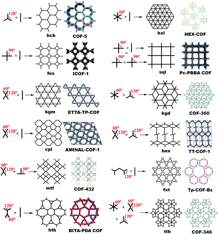 | ||
| Fig. 1 Topological design for 2D COFs guided by suitable symmetries and angularity of their planar building blocks. | ||
2.2 Topologies of 3D COFs
All the above-mentioned combinations with an appropriate planar geometry of organic monomers and suitable topological connectivities give rise to stacked 2D COF sheets. To increase the dimensionality of the framework, a deviation from planarity and implementation of geometric constraints over the building units are prominent choices.42 There are 15 topologies (Fig. 2) known thus far, in which 3D COFs are tessellated, six of which use monomers with a Td geometry, for instance, dia (diamond net), ctn (cubic-C3N4), bor (borcaite net), pts (platinum sulfide) net, ljh (Luojia Hill), lon (lonsdaleite) and rra. A few reports have been found in which the planar building units connect in such a way that they knit three-dimensional COFs, which are srs (SrSi2 net), ffc, tbo (twisted boracite) and fjh. The former utilizes the [C3 + C3] combination, whereas the other three amalgamates the triangular C3 unit with a C4 symmetric monomer unit with varying geometry (rectangular or square planar). An expansion in the topological library of 3D COFs is seen when high connectivity building units (C6 and C8) have been reported to give stp, acs, ceq and bcu (body-centered cubic) nets. Various examples of 3D COFs with different topological designs are elaborated as follows.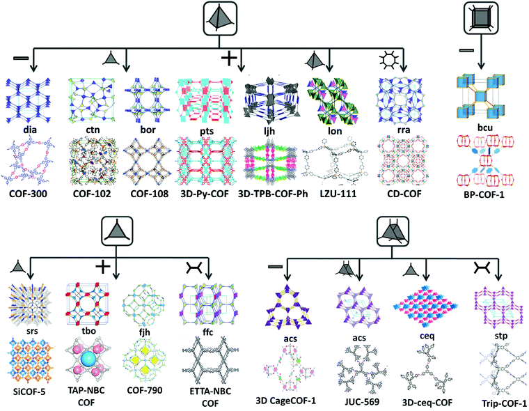 | ||
| Fig. 2 Topological designs for 3D COFs guided by combining symmetrical, planar and non-planar building blocks. | ||
3. Classification of COFs
3.1 Based on their linkages
There are numerous linkages used for constructing COFs with high crystallinity, stability towards heat, chemicals and water, and enormous surface areas with sizeable pores and functionalization (Fig. 3). Topological diversity can help explain the use of these linkages. COFs with good crystallinity, exceptional stability and multiple functionalization are challenging to synthesize given that control of their growth is required (long-range order), but functionalization results in the loss of this control. Furthermore, thermal, chemical and hydrolytic stability are other challenges to overcome within a single framework. An attempt to combine different synthetic strategies to engineer the desired COFs was envisioned by Lotsch and co-workers last year.58 It is known that by employing dynamic covalent chemistry, one can control the covalent bond formation rate. Accordingly, introducing reversible linkages within the framework of COFs causes them to be more crystalline, robust and resistant upon exposure to heat; however, their stability towards moisture and several organic and inorganic chemicals is sacrificed. For instance, the first thermally stable and ordered boroxine and boronic ester-linked COFs, namely, COF-1 and COF-5, disintegrate in the presence of water following Le Chatelier's principle. Water, as the by-product, shifts the reaction to the backward direction, limiting or preventing the formation of a COF. Recent studies have shown that to maintain the ‘error-correction’ and ‘proofreading’ during COF synthesis, a calculated amount of H2O (∼15 equiv.) is required to get highly crystalline COF-5 with controlled crystallite sizes.5 The COF would not be formed when water content is increased to 20 equiv. However, functionalizing the linkers with alkyl chains in boron-containing COFs can provide resistance to aqueous medium to some extent.59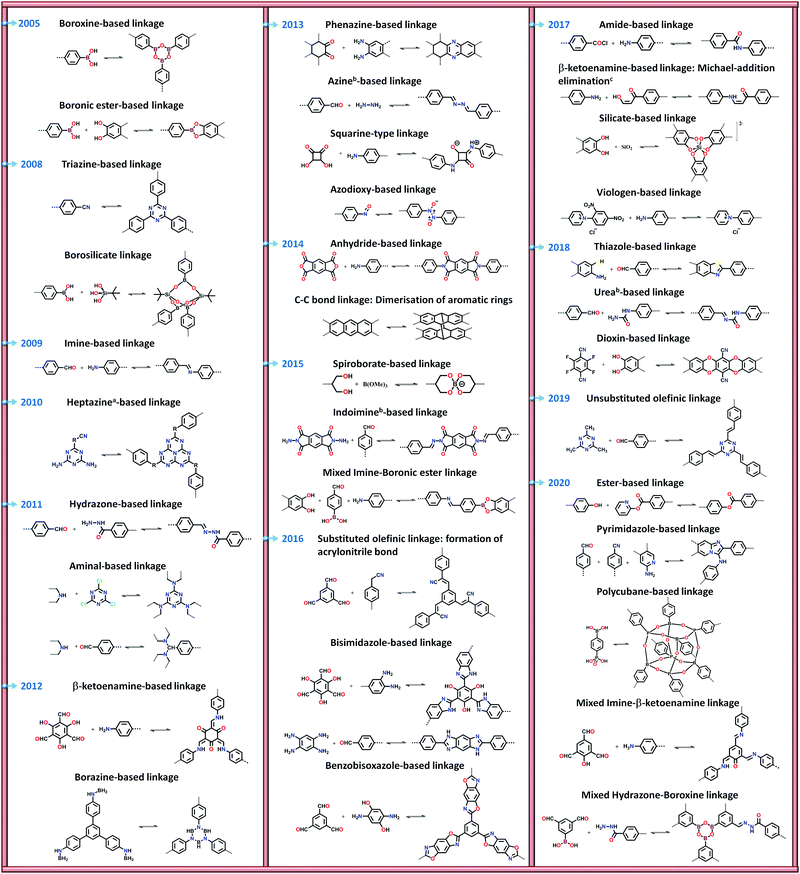 | ||
Fig. 3 Types of linkages in COFs with a timeline for their discovery and progress. a![[thin space (1/6-em)]](https://www.rsc.org/images/entities/char_2009.gif) Subclass of imine linkages, b Subclass of imine linkages, b![[thin space (1/6-em)]](https://www.rsc.org/images/entities/char_2009.gif) subclass of hydrazone linkages and cfalls under β-ketoenamine linkage. subclass of hydrazone linkages and cfalls under β-ketoenamine linkage. | ||
Further attempts have been made to increase the stability of COFs in thermal, chemical and humid environments by incorporating N-containing bonds within their framework. The various linkages containing a nitrogen heteroatom include triazine, imine, heptazine, hydrazone, aminal, phenazine, azine, squarine, azidoxy, anhydride, indoimine, nitrile-substituted olefin, amide, viologen, urea, and pyrimidazole, as shown Fig. 3. These N-containing linkages enrich the framework with robust reversible bonds and provide protection against different organic and inorganic chemicals and moisture. Based on a detailed study and literature comparison, it can be perceived that the COFs enriched with N-centres are highly crystalline, possess great stability and can tolerate functionalization of their framework compared to boron-based linkages (Table 1).
| Linkage | Framework | Thermal stability (°C) | Chemical stability | Hydrolytic stability | Reason | Linkage | Framework | Thermal stability (°C) | Chemical stability | Hydrolytic stability | Reason |
|---|---|---|---|---|---|---|---|---|---|---|---|
| a NR = not reported. | |||||||||||
| Boronic ester |

|
NR | NR | Stable for ∼17 h | Hydrophobic alkyl chains | Dioxin |

|
∼400 | 12 M HCI for 3 days and 6 M NaOH | NR | Bond locking by irreversible nucleophilic aromatic substitution (SNAr) |
| Borazine |

|
∼420 | NR | NR | — | Silicate |

|
∼500 | Stable in acetone, CH2Cl2, CH3, CN, MeOH, THF and in air | NR | NR |
| Imine |

|
>300 | NR | Stable | Strong π–π interactions | β-Keto enamine |

|
∼350 | 9 N HCl | Stable for ∼7 days | Bond locking by irreversible tautomerism |
| Imine |

|
400 | 1 M HCI and 1 M NaOH for 7 days | NR | Strong π–π interactions | Bisimidazole |

|
∼400 | 3 NHCI and 3 N NaOH for 7 days | NR | Bond locking by cyclization followed by dehydrogenation reaction |
| Hydrazone |

|
∼280 | Stable in THF, CHCl3, PhMe, MeOH | Water unstable | Hydrolysis of framework | Benzo bisoxazole |

|
350 | Stable in organic solvents | Stable for 24 h | Bond locking by ring closure and oxidation reaction |
Linkages such as borazine, borosilicate and polycubane were obtained by introducing N, Si and P atoms in boron-rich frameworks, endowing the frameworks with exceptional crystallinity, but their chemical and hydrolytic stabilities are still lacking.57,60,61 Some oxygen-containing linkages have also contributed to the stability, i.e., dioxin, ester and silicate-based, examples of which are shown in Table 1.49,62,63 To explore more traits, the chemistry of knitting a framework with two different linkages was practiced. The N-rich imine linkage was intermixed with boroxine (or boronic ester) and β-ketoenamine to enhance the crystallinity and stability.64,65 Furthermore, the boroxine and hydrazone linkages were taken in a single framework to overcome the chemical stability limitation and allow selective hydrolysis in the framework.66 These COFs are known as double-stage COFs.
Lately, it has been found that incorporating reversibility during the synthesis of COFs is not the only route to attain all the required properties in one frame. Hence, combining reversible covalent bond-forming reactions with irreversible non-covalent interactions has gathered increasing attention to solve the above-mentioned problem. Remarkably, stable materials with intact crystallinity in harsh acidic, basic and aqueous conditions have been synthesized using this strategy, which can also withstand chemical functionalities tied up on the framework. These linkages are β-ketoenamine,67 bis(imidazole),68 benzo-bis(oxazole)69 and thiazole70 (Fig. 4). In these types of linkages, the pre-orientation of the building units to induce order via reversible linkages provides crystallinity and irreversible locking of the bonds to induce stability in the framework synergistically.
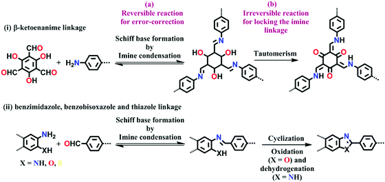 | ||
| Fig. 4 Strategy for the synthesis of highly stable N-containing linkages by (a) reversible and (b) irreversible reactions. | ||
Nevertheless, the fabrication of ordered COFs solely using irreversible reactions is a very cumbersome process. However, by limiting the flexibility and reducing the degree of freedom in the building units, a kinetically controlled but crystalline framework can be obtained. One example of this was reported by Liu et al. in 2017, where a highly ordered 2D-CAP COF from the exceptionally rigid 2,7,13,18-tetrabromodibenzo[a,c]dibenzo [5,6:7,8] quinoxalino[2,3-i]phenazine (2-TBQP) building block was successfully engineered.71 In addition to the 2D framework, an energetically less favourable 1D-CAP was formed. The 2D polymer was formed via metal-surface-mediated polymerization at an elevated temperature of ∼250 °C, where the debromination of 2-TBQP and aryl–aryl coupling reaction occurred. A similar example of an irreversible C–C coupling reaction was reported the next year, in 2018, forming highly conjugated 2D aromatic polymers, viz., CAP-1 and CAP-2, at high temperature and under an inert atmosphere (Fig. 5).72 A few other COFs synthesized using irreversible Ullmann, Suzuki-Glaser73,74 and Horner–Wadsworth–Emmons reactions75 were also reported.
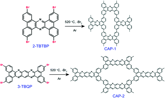 | ||
| Fig. 5 Schematic representation of the formation of CAP-1 and CAP-2 by irreversible C–C coupling reactions. Reproduced with permission from ref. 72, Copyright the American Chemical Society (2018). | ||
3.2 Based on their dimensionality
Considering their dimensionality, COFs are categorized as 2D and 3D COFs. As explained earlier in Section 2, following the topological delineation of 2D COFs, planar building units from the diverse list of monomers are used, whereas deviation from planarity is one of the requirements to yield 3D frameworks. In this section, we focus on the chemistry involved in the formation of 2D and 3D frameworks using covalently bonded organic units.Various reversible linkages have been proposed to gain an ordered 2D sheet (discussed in Section 3.1). On the contrary, the supramolecular interactions that stick the planar sheets together are somewhat less explored.78 A few examples are discussed below to give insight into the different types of supramolecular interactions, depending on the geometry and orientation of the monomers.
Constructed with strong van der Waals forces. Boronic ester-linked COFs were the first COFs to be synthesized and well-studied to discover their core chemistry. These frameworks are stacked on each other with strong van der Waals forces between two robust 2D COF layers. A detailed computational study was carried out on HHTP-DPB COF, where planar and highly rigid monomers were utilized under solvothermal conditions.18 The results from molecular mechanics and density functional theory indicate slight offset stacking (∼1.7–1.8 Å) of the layers, which is not feasible to determine using the common characterization methods, but can be observed by SCXRD. This offset places the boron atoms of one layer in close proximity to the O-atoms of the adjacent layer, thereby building strong dipole–dipole interactions, which stick the 2D sheets together. The results are more accurate with density functional theory given that it precisely considers the electrostatic interactions for simulation.
Constructed with aromatic π–π stacking. The planarity of the monomers after their assembly within a framework is vital to achieve a good magnitude of certain bulk properties. An excellent example of this was reported in 2016 by Banerjee and co-workers, yielding two imine-based COFs 2,3-DhaTta and 2,3-DhaTab, via the combination of 2,3-dihydroxyterephthaldehyde with triazine and phenyl-core triamine, respectively (Fig. 6).79 During the reversible imine bond formation, it was reported that planarity of the triazine-core with respect to the peripheral phenyl rings was achieved with angles of ∼174°–179°, whereas in the case of the phenyl core, deviation from planarity with angles of ∼145°–154° was observed. Intralayer H-bond formation between the imine N and diols caused additional planarity to the 2D sheet, although there was a tilt of ∼134° between the triamine and terephthaldehyde units. Consequently, strong aromatic π–π stacking was observed in 2,3-DhaTta, forming ribbon-like structures in comparison to 2,3-DhaTab with a hollow sphere. This was evident from the BET surface area calculations with a high surface area of 1700 m2 g−1 for the more planar and stacked 2,3-DhaTta, which also showed nine-times more intense PXRD reflections (100 to 001 plane) compared to the value of 413 m2 g−1 for 2,3-DhaTab.
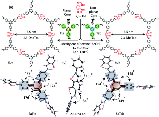 | ||
| Fig. 6 (a) Strategy for the formation of COFs 2,3-DhaTta and 2,3-DhaTab. (b–d) Angle between the planes of triazene and phenyl core with phenyl substituents and that with a diol moiety. Reproduced with permission from ref. 79, Copyright John Wiley and Sons (2016). | ||
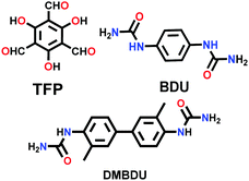
Constructed with hydrogen bonding. Some cases have been recorded where the 2D COF sheets are stacked together by hydrogen bonding. This requires that the atoms with the ability to form hydrogen bonds be oriented in close proximity to fulfil the hydrogen-bonding conditions. As examples, six different COFs have been reported, namely TPOMe-Tab, TPOMe-PaNO2, TPOMe-Pa1, TPOMe-BD(NO2)2, TPOMe-BPy and TPOMe-Azo, which were synthesized from trimethoxy-substituted benzenetricarboxaldehyde (TPOMe) with six different diamines.80 Except for the TPOMe-BD(NO2)2 COF, they all have OMe groups perpendicular to the planar COF sheets, which favourably form interlayer hydrogen bonds. In addition, the methoxy groups provide steric hindrance around them, which generates a hydrophobic environment for the framework as a whole. Hence, the COFs resist very harsh acidic (18 M conc. H2SO4 and 12 M conc. HCl for 7 d), basic (9 M NaOH for 1 d) and moisture conditions. The utilization of flexible monomers for the construction of hydrogen-bonded 2D COFs is a much more laborious challenge than that with planar monomers. Thus, only the urea-functionalized COFs, COF-117 and COF-118, reported by Yaghi and co-workers in 2018 give a comparative study to emphasize this point.81 The variation in their surface areas, i.e., 114 m2 g−1 (COF-117) and 1524 m2 g−1 (COF-118), is due to the different conformations of the urea molecule. The disruption of the C–N⋯H bond in COF-117 is attributed to the bond rotations in the pliable units, which were confirmed by FTIR spectroscopy before and after the introduction of acetonitrile solvent guest molecules.
As discussed in the preceding paragraphs, there are numerous examples of 2D COFs with supramolecular interactions of various types that produce microcrystalline powders. Supramolecular interactions, which are weaker in comparison to covalent bonds, provide reversibility to the reaction, but still it is difficult to obtain single crystals of 2D COFs. A detailed analysis of this has been extensively done by various groups, elaborating various factors in controlling the crystallinity of 2D COFs (see Section 4.3).
Polycrystalline. Most 3D COFs are polycrystalline solids prepared mainly via the solvothermal technique. To generate highly ordered 3D COFs, the reaction conditions must be monitored in a proper and regular manner. Various parameters such as choice of solvents and their optimized composition, reaction temperature and environment (vacuum, N2 or air), time required for completion of the reaction, and amount of catalyst added are the major factors that control the reversibility of the reaction, yielding a multi-crystalline material. As mentioned in Section 3.1, the various linkages developed thus far use dynamic covalent chemistry to achieve the desired crystallinity.
The very first polycrystalline 3D COF was reported to possess a boroxine and boronic-ester linkage, which was synthesized solvothermally in 2007 by Yaghi and co-workers.45 Subsequently, the formation of the first imine-linked 3D COF was reported in 2009 by the same group.82
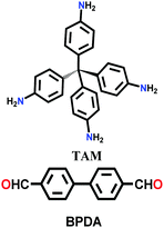
Since then, many of these frameworks have been reported by solely controlling the reaction conditions. Several other greener techniques have also been used to increase the uniformity and maintain high dimensionality in COFs, including mechanochemical,83 microwave-assisted,84 ionothermal,85 devitrification86 and linker exchange methods87 (see Section 4.1 for details). Basically, devitrification is the process of obtaining a crystalline material from an amorphous material. CAF-1 and CAF-2 with long-range order were synthesized by heating the corresponding amorphous polyamide networks, namely PATnC and PATCnC, respectively, at 240–250 °C for 7 days in the presence of 15 meq water.86 In addition, a 3D-to-3D COF transformation happened from COF-320 to COF-300 via a heterogeneous linker exchange method.87 Initially, the 3D COF-320 net was formed solvothermally from biphenyl-4,4′-dicarbaldehyde (BPDA) and tetra-4-anilylmethane (TAM). Afterwards, COF-320 was subjected to the linker exchange process with terephthaldehyde (TA) under solvothermal conditions, yielding COF-300. An appropriate amount of acid catalyst was required to activate the TA linker for the exchange reaction, as shown in Fig. 7a.
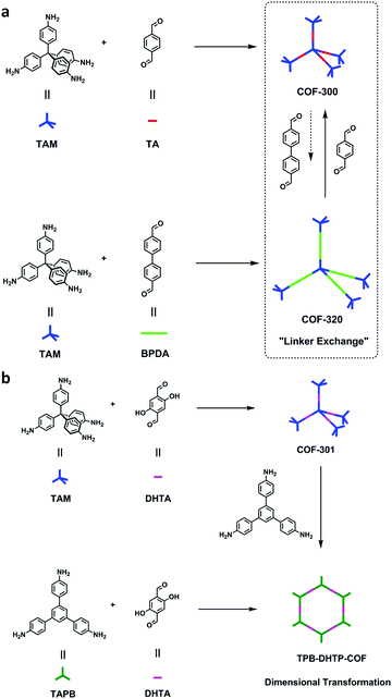 | ||
| Fig. 7 (a) Synthesis of COF-300-to-320-X and COF-320-to-300-X. (b) Synthesis of COF-301-to-TPB-DHTP-COF-X ((X = (n1/n2) × 100, where n1/n2 is the molar ratio of the exchanging monomer to initial COF; X = 5, 10, and 15). Reproduced with permission from ref. 87, Copyright the American Chemical Society (2019). | ||
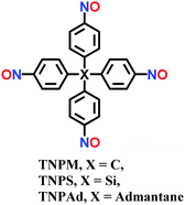
Single-crystalline. In recent years, mechanistic studies have focused on insight into improving the crystallinity of 2D COFs, while single crystals have only been obtained for 3D COFs. The first single crystal of a 3D COF was reported in 2013, namely, NPN-1, NPN-2 and NPN-3, which were synthesized via the oxidation of hydroxylamines, yielding tetrakis(4-nitrosophenyl)-substituted methane, silane and adamantane, and subsequent polymerization yielded large and uniform crystals of approximately 0.5 mm in size (for NPN-3).88 In the same year, Zhang et al. proposed the crystal structure of the 3D imine-linked COF-320 (with size of ∼200 nm) using the rotation electron diffraction technique (Section 5.4.2). The 9-fold interpenetrated net was woven solvothermally using tetra-(4-anilyl)methane and 4,4′-biphenyldialdehyde with the dia topology.89 Fortunately, large-sized single crystals (∼ 60 μm) of 3D imine-based COFs were obtained, namely COF-300 (hydrated), COF-303, LZU-79, and LZU-111 with dia and lon nets (Section 2, vide supra), which were successfully diffracted using the SCXRD technique (Section 5.3.2).6 This propelled the expansion of single-crystal COF chemistry, emphasizing certain requirements.
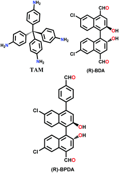
Interpenetrated nets. Another remarkable feature of 3D frameworks is their interpenetrating capability to give a thermally strong and stable net. Almost all 3D COFs become tangled during their synthesis, and only a few examples are have been reported with non-interpenetration (cited in Section 2). The highest interpenetration in a 3D COF was recently reported with the chiral COF-16, which forms a 11-fold interpenetrated diamondoid-network.90 A more interesting interpenetration isomerism was witnessed by Ma et al. in 2018, where COF-300 was found to exist in two distinct isomers, dia-c7 and dia-c5, based on its degree of interpenetration.91 The factor of aging plays a role in their synthesis given that the formation of COF-300 dia-c5 requires a three-day solvothermal process, whereas COF-300 dia-c7 was synthesized in 9 days with a gradual increase in temperature from 25 °C to 50 °C, and finally 120 °C for 3 days each.
4. Synthesis
The synthesis of robust porous organic polymers via covalent bonds with in-built crystallinity is challenging. The comprehensive discussion in the previous sections elaborates the importance of the reversible dynamic covalent chemistry for the synthesis of COFs. COF chemistry requires thermodynamically controlled organic reactions, which help in correcting and reforming the wrong bond and proofreading each step.93 Several synthetic methods have been developed to incorporate crystallinity and stability in COFs, making them potent materials for sensing applications. Recently, crystalline COF powders and films have been extensively utilized as sensory materials, which have been synthesized using various methods, as mentioned in detail below.4.1 General synthetic methods
In this section, we discuss the various methods utilized for the synthesis of COFs and modifications for their applications. All the reported synthetic methods are different in terms of maintaining the reaction conditions, choice and amount of solvent, reaction temperature, time consumed, requirement of catalysts, and the source of energy, which helps in the formation of a particular framework in each case. A detailed comparison is shown in Table 2.| Synthetic method | Energy source | Reaction conditions | Solvent environment | Reaction time | Product formation |
|---|---|---|---|---|---|
| Solvothermal | Thermal energy | • High temperature and autogenous pressure | • High boiling solvents | • 2 to 9 days | • Gram-scale (comparatively high yields for 2D COFs are seen) |
| • High vacuum conditions | • Non-polar solvents reduce the reaction homogeneity, which further increases time to attain thermodynamically-controlled product | • Interpenetration reduces the %yield | |||
| • Freeze–pump–thaw process for proper degassing of solvents | • Depends upon the solubility and reactivity of the starting materials | ||||
| Mechanochemical | Mechanical energy | • Ambient conditions | • No or minimum solvent is required | • Several minutes to a few hours | • Good yields obtained but with lower surface areas |
| • Constant grinding | |||||
| Microwave-assisted | Microwave radiations | • Moderate temperature and autogenous pressure | • No harsh solvent conditions are required | • Faster compared to other methods | • Higher yields but with reduced surface areas |
| lonothermal | Thermal energy | • Extremely high temperature conditions | • Ionic solids in molten form act as solvents and catalyse the reaction | • Prolonged reaction time required to reduce side-product formation | • Good yields but limited crystallinity of frameworks |
| Room temperature synthesis | No external energy | • Ambient conditions | • Solvents are chosen according to solubility of the monomers | • Several minutes to a few hours | • Reduction of yields of well-defined frameworks due to solubility |
| • Constant stirring |
![[thin space (1/6-em)]](https://www.rsc.org/images/entities/b_char_2009.gif) :
:![[thin space (1/6-em)]](https://www.rsc.org/images/entities/b_char_2009.gif) 2). The third layer contains monomer B immersed in solvent 2. The two solvents taken must be miscible at a slow rate to form smooth and periodic thin COF films.
2). The third layer contains monomer B immersed in solvent 2. The two solvents taken must be miscible at a slow rate to form smooth and periodic thin COF films.
Alternatively, the fabrication of solid/vapour interfacial thin films is carried out over an HOPG surface. In the typical synthetic procedure, a drop of monomer A solution is impinged over the substrate, and then introduced in a Teflon-sealed autoclave, which contains monomer B with CuSO4·5H2O. It should be noted that both monomers are not in direct contact. The whole system is sealed and subjected to high temperature for a few hours. Precursor B evaporates at high temperature and comes in contact with monomer A, resulting in the formation of covalent bonds at the solid/vapour interface. The rate of the vapour-phase monomer dosage decides the growth of the COF.
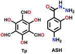
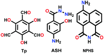
In some cases, it has been observed that the COF nanofilms lose their stability in the dispersion medium after they are peeled from the bulk powder. Therefore, the chemical exfoliation approach is carried out, which provides dispersion stability to the nanosheets. The nanosize of the thin films primarily varies with the concentration of the powder suspension. At a higher concentration, more sheets will be in proximity to form thick films. An example of this is the DaTp COF, where N-hexylmaleimide was used at high temperature to conduct delamination with great stability.110N-Hexylmaleimide undergoes Diels–Alder reaction with the anthracene units in Da and increases the hydrophobic alkyl–alkyl interactions among the 2D layers. The process was well monitored by FT-IR and PXRD analysis. Post-synthetic modification by chemical delamination was also performed during the thin film synthesis of the TpASH COF, which was further exploited for drug delivery appications.111
A few cases have been reported where self-exfoliation of the framework occurs, leading to the formation of thin nanofilms. In this case, the choice of the building units, which leads to delayering via internal force, is important. No external force is required for carrying out this process. Few-layered IISERP-CON1 nanofilms with a thickness of ∼2–6 nm and aspect-ratio of <0.1 were fabricated using the above-mentioned technique.112 Moreover, a few ionic covalent organic nanosheets (iCONs) were self-exfoliated due to the interlayer repulsions caused by the positively charged guanidinium monomeric unit, including TpTGx (x = Cl−, Br− and I−) iCONs113 possessing 3–6 layers with a size of 2–5 nm and DATGCliCONs114 possessing 13–18 layers with a size of 5–7 nm. The iCONs formed showed chemical and water stability and retained their ionic properties after self-exfoliation.
In addition to these methods, the continuous flow method115,116 and hydrothermal method117 were employed to produce direct and free-standing COF nanosheets via the bottom-up approach. Nanofilms of COF-5, which is the first COF reported to be formed by boronic ester linkages, with a thickness of ∼70–200 nm have been successfully formed.
4.2 Reaction conditions for diverse linkages
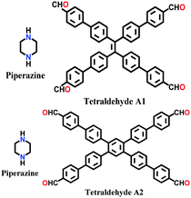
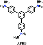
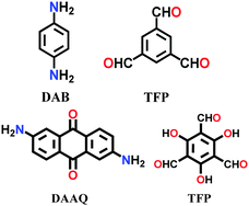
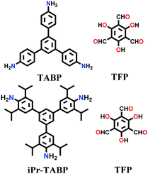
In this section, we selected examples from Table 3 for all the linkages mentioned in Fig. 3 to discuss the reaction conditions used for their synthesis. We apologise to researchers for not being able to include their examples given that it is very difficult to present all the examples available in the literature in this review. The heart of COF chemistry is the choice of the monomers, except in few cases, where it involves only one component such as boroxine and triazine-based COFs and the complementary monomers in the two-component system form the linkages. For nitrogen-rich COFs, there are four types of monomers, namely nitriles, amines, aldehydes and hydrazones. Furthermore, there are eleven nitrile-based, forty-eight amine-based, thirteen aldehyde-based and fourteen hydrazine-based monomers used thus far. Interestingly, the distribution of amines (twenty-five diamines, nine triamines, two C2-symmetric tetramines, nine C4-symmetric tetramines, one C2-symmetric hexamine and three C6-symmetric hexamines) is less than even aldehydes (thirteen dialdehydes, fifteen trialdehydes, eleven tetra-aldehydes and one hexa-aldehyde).| Entry | Linkage | COF | Monomers used | Synthesis method | Topology | SAa (pore size) m2 g−1 (nm) | Ref. |
|---|---|---|---|---|---|---|---|
| a Surface area (SA) by BET except those marked with b. b Langmuir surface area. N.R. = not reported. | |||||||
| 1 | Boroxine anhydride | COF-1 |

|
Solvothermal; mesitylene/1,4-dioxane; 120 °C for 72 h | hcb(gra) | 711 (0.6–1.2) | 4 |
| COF-102 |
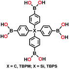
|
Solvothermal; mesitylene/1,4-dioxane; 85 °C for 4 d | ctn | 3472 (1.15) | 44 | ||
| COF-103 | 4210 (1.25) | ||||||
| 2 | Boronic ester | COF-5 |

|
Solvothermal; mesitylene/dioxane; 120 °C for 72 h | hcb(bnn) | 1590 (2.7) | 4 |
| Microwave-assisted; mesitylene/1,4-dioxane, 100 °C, 200 W for 20 min | 2019 (N.R.) | 95 | |||||
| COF-11 Å, COF-14 Å, COF-16 Å, COF-18 Å |

|
Conventional; THF/CH3OH (99![[thin space (1/6-em)]](https://www.rsc.org/images/entities/char_2009.gif) : :![[thin space (1/6-em)]](https://www.rsc.org/images/entities/char_2009.gif) 1); Refluxed under N2 for 72 h 1); Refluxed under N2 for 72 h |
105 (1.1) | 198 | |||
| 805 (1.4) | |||||||
| 753 (1.6) | |||||||
| 1263 (1.8) | |||||||
| COF-6, COF-8, COF-10 |
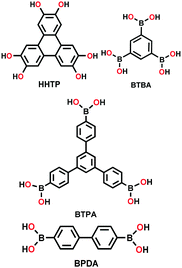
|
Solvothermal; mesitylene/1,4-dioxane; 85 °C for 48–120 h | 980b (0.64) | 23 | |||
| 1400b (1.87) | |||||||
| 2080b (3.41) | |||||||
| COF-105 |
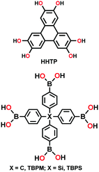
|
Solvothermal; mesitylene/1,4-dioxane; 85 °C for 4 d | ctn | (N.R.) | 45 | ||
| COF-108 | bor | ||||||
| Py-DBA-COF-1, Py-DBA-COF-2, Py-MV-DBA-COF |
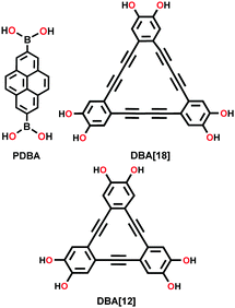
|
Solvothermal; mesitylene/1,4-dioxane (2![[thin space (1/6-em)]](https://www.rsc.org/images/entities/char_2009.gif) : :![[thin space (1/6-em)]](https://www.rsc.org/images/entities/char_2009.gif) 1) (v/v); 105 °C for 72 h 1) (v/v); 105 °C for 72 h |
bnn | 1392 (3.6) | 212 | ||
| 1354 (4.3) | |||||||
| 1134 (4.1) | |||||||
| 3 | Boro-silicate | COF-202 |
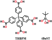
|
Solvothermal; 1,4-dioxane/toluene (1![[thin space (1/6-em)]](https://www.rsc.org/images/entities/char_2009.gif) : :![[thin space (1/6-em)]](https://www.rsc.org/images/entities/char_2009.gif) 2) (v/v); 120 °C for 3 d 2) (v/v); 120 °C for 3 d |
ctn | 2690 (1.1) | 61 |
| 4 | Triazine | CTF-1 |

|
Ionothermal synthesis; Molten ZnCl2; 400 °C in a quartz ampoule for 40 h | hcb | 791 (1.2) | 20 |
| CTF-2 |

|
Ionothermal synthesis; Molten ZnCl2; 400 °C in a quartz ampoule for 40 h | hcb | 2255 (0.8) | 118 | ||
| P1M, P2M, P4M |
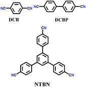
|
Microwave; CF3SO3H; 110 °C for 30 min | hcb | 4 (N.R.) | 119 | ||
| 464 (1.5–2) | |||||||
| 542 (2–4) | |||||||
| CTF-0 |

|
Ionothermal Synthesis; ZnCl2; 400 °C in a quartz ampoule for 40 h | hcb | 400–500 | 19 | ||
| (N.R.) | |||||||
| FCTF-1 |

|
Ionothermal Synthesis; ZnCl2; 400 °C or 600 °C in a Pyrex ampoule for 40 h | hcb | 623 (0.46, 0.54) | 120 | ||
| FCTF-1–600 | 752 (0.46, 0.59) | ||||||
| mCTF, PTF-550, PTF-600, PTF-650, PTF-700 |

|
Ionothermal Synthesis; Molten ZnCl2; 400 °C for mCTF; 550 °C for PTF-550; 600 °C for PTF-600; 650 °C for PTF-650 700 °C for PTF-700 | hcb | 1212 | 121 | ||
| 1419 | |||||||
| 1964 | |||||||
| 2482 (∼0.7) | |||||||
| 5 | Triazine-imine linkage | TRITER-1 |

|
Refluxed (inert atmosphere); anhydrous DMF; 150 °C for 12 h | hcb | 716 (1.7) | 128 |
| 6 | Imine | COF-300 |
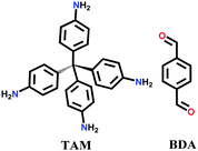
|
Solvothermal; 1,4-dioxane/3M aq. AcOH 10![[thin space (1/6-em)]](https://www.rsc.org/images/entities/char_2009.gif) : :![[thin space (1/6-em)]](https://www.rsc.org/images/entities/char_2009.gif) 2 (v/v); 90 °C for 2 d 2 (v/v); 90 °C for 2 d |
dia | 1360 (0.72) | 82 |
| SCOF-IC1 |
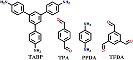
|
Solid/vapour interfacial; in a closed system; 150 °C for 3h | hcb | N.R. | 101 | ||
| SCOF-LZU1 | |||||||
| IL-COF1 |
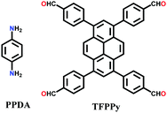
|
Solvothermal; 1,4-dioxane/aq. AcOH; 120 °C for 3 d | sql | 2723 (1.0, 1.7, 2.3) | 122 | ||
| SCOFA+B |
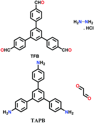
|
Solid/vapour interfacial; preloaded on freshly cleaved HOPG; water/THF; Heating at 140 °C for 3 h (SCOFA+B); Heating at 80 °C for 3 h (SCOFC+D) | hcb | N.R. | 127 | ||
| SCOFC+D | |||||||
| COF-LZU1 |

|
Solvothermal; 1,4-dioxane/3 M aq. AcOH; 120 °C for 72 h | hcb | 410 (1.2) | 116 | ||
| COF-300 [(TAM) (BDA)2]imine, COF-303 [(TAM) (BDA)2]imine, LZU-79, chiral LZU-111 |
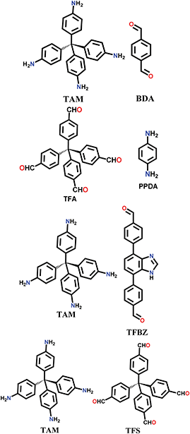
|
Solvothermal; 1,4-dioxane/6 M aq. AcOH; 120 °C for 72 h | dia (COF-300, COF-303, LZU-79) | 2120 (LZU-111) | 6 | ||
| lon-b-c3 (LZU-111) | |||||||
| LZU-306 |
|
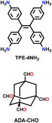
Conventional method with modulation strategy; aniline (50 equiv.), 1,4-dioxane, AcOH; 30 °C for 25 d | pts | 2056 (1.09) | 16 | ||
| COF-346 |
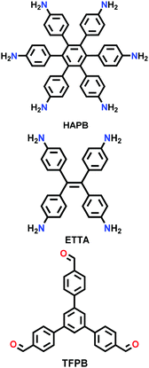
|
Solvothermal; DCB/n-BuOH; 120 °C for 72 h | tth | 1081 (1.04, 2.19) | 34 | ||
| SNW-1 |

|
Microwave synthesis; N2 atmosphere; 280 W for 6 h | (N.R.) | 476 (40) | 232 | ||
| PT-COF |
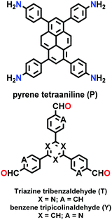
|
Solvothermal; mesitylene/1,4-dioxane (1/1); 120 °C for 3 d | bex | 1791, 1220 (1.77–1.83) | 39 | ||
| PY-COF | |||||||
| IISERP-COF7 |

|
Solvothermal; mesitylene/1,4-dioxane (1![[thin space (1/6-em)]](https://www.rsc.org/images/entities/char_2009.gif) : :![[thin space (1/6-em)]](https://www.rsc.org/images/entities/char_2009.gif) 1); 120 °C for 5 d 1); 120 °C for 5 d |
hcb | 657 (2.7) | 223 | ||
| SIOC-COF-X (X = 1,2) |
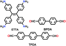
|
Solvothermal; toluene/1,4-dioxane/9 M aq. AcOH; 120 °C for 3 d | kgm | 478.41 (0.73, 1.18, 3.06) | 207 | ||
| 46.13 (1.13, 1.38, 3.27) | |||||||
| TP-COF-DAB |
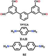
|
Solvothermal; DMAc/mesitylene (1![[thin space (1/6-em)]](https://www.rsc.org/images/entities/char_2009.gif) : :![[thin space (1/6-em)]](https://www.rsc.org/images/entities/char_2009.gif) 2); 120 °C for 3 d 2); 120 °C for 3 d |
fxt | 302.78 (1.61, 3.18) | 36 | ||
| TP-COF-BZ | 518.94 (2.56, 3.91) | ||||||
| SIOC-COF-5 |
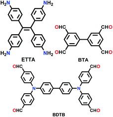
|
Solvothermal; DMAc/mesitylene (5![[thin space (1/6-em)]](https://www.rsc.org/images/entities/char_2009.gif) : :![[thin space (1/6-em)]](https://www.rsc.org/images/entities/char_2009.gif) 15); 120 °C for 7 d 15); 120 °C for 7 d |
N.R. | 707 (0.81, 1.38) | 208 | ||
| SIOC-COF-6 | 1617 (1.02, 1.66) | ||||||
| COF-4-OH |
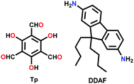
|
Solvothermal; aniline/AcOH/1,4-dioxane; 120 °C for 5 d | hcb | 34 (0.5) | 225 | ||
| HAT-NTBCA-COF |
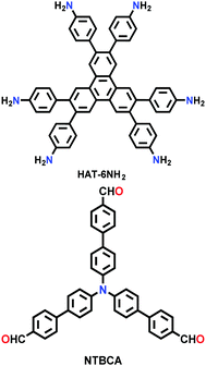
|
Solvothermal; DMAc/mesitylene (1![[thin space (1/6-em)]](https://www.rsc.org/images/entities/char_2009.gif) : :![[thin space (1/6-em)]](https://www.rsc.org/images/entities/char_2009.gif) 1); 120 °C for 3 d 1); 120 °C for 3 d |
kgd | 439.9 (1.27) | 33 | ||
| COF-432 |
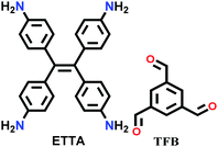
|
Solvothermal; chloroform/methanol/aq. acetic acid (0.6/0.4/0.2); 120 °C for 3 d | mtf | 895 (0.8) | 40 | ||
| BITA-PDA-COF |
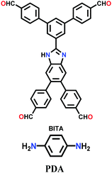
|
Solvothermal; aq. acetic acid (9 M)/1,2-DCB/ethanol (2![[thin space (1/6-em)]](https://www.rsc.org/images/entities/char_2009.gif) : :![[thin space (1/6-em)]](https://www.rsc.org/images/entities/char_2009.gif) 13 13![[thin space (1/6-em)]](https://www.rsc.org/images/entities/char_2009.gif) : :![[thin space (1/6-em)]](https://www.rsc.org/images/entities/char_2009.gif) 13 v/v/v); 110 °C for 5 d 13 v/v/v); 110 °C for 5 d |
htb | 940 (1.0, 1.7, 3.3) | 41 | ||
| Trip-COF-x (x = 1,2) |
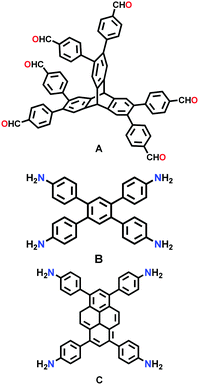
|
Solvothermal; 1,2-DCB/n-butanol/acetic acid (8![[thin space (1/6-em)]](https://www.rsc.org/images/entities/char_2009.gif) : :![[thin space (1/6-em)]](https://www.rsc.org/images/entities/char_2009.gif) 2 2![[thin space (1/6-em)]](https://www.rsc.org/images/entities/char_2009.gif) : :![[thin space (1/6-em)]](https://www.rsc.org/images/entities/char_2009.gif) 1); 120 °C for 3 d 1); 120 °C for 3 d |
stp | 1473 (1.26, 2.96, 3.99) | 54 | ||
| 1624 (1.26, 2.93) | |||||||
| TpBDH, TfpBDH COF |
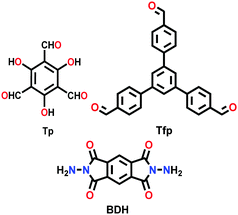
|
Solvothermal; 1,4-dioxane/DMAc (1/2); 6 M AcOH; 120 °C for 3 d | hcb | 642 (2.4) | 149 | ||
| hxl | 738 (1.6) | ||||||
| TPE-TAP-COF |
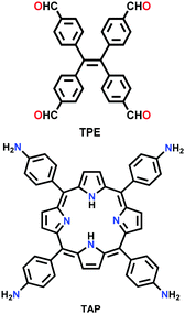
|
Solvothermal; toluene/1,4-dioxane (1![[thin space (1/6-em)]](https://www.rsc.org/images/entities/char_2009.gif) : :![[thin space (1/6-em)]](https://www.rsc.org/images/entities/char_2009.gif) 1); 6 M AcOH acid; 150 °C for 3 d 1); 6 M AcOH acid; 150 °C for 3 d |
dia | 218 (1.6) | 190 | ||
| 4PE-xP-COF (x = 1,2,3) |
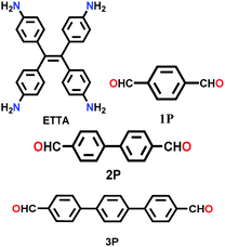
|
Solvothermal; mesitylene/1,4-dioxane; 6 M AcOH; 120 °C for 4 d | kgm | 2140 (2.9, 1.6) | 27 | ||
| 2070 (3.8, 1.7) | |||||||
| 1000 (4.5, 1.8) | |||||||
| 4PE-TT |
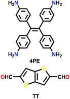
|
Solvothermal; benzyl alcohol/mesitylene; 6 M AcOH; 120 °C for 3 d | kgm | 1990 (3.3, 1.6) | 27 | ||
| TPE-Por-4, TPE-Por-2 |
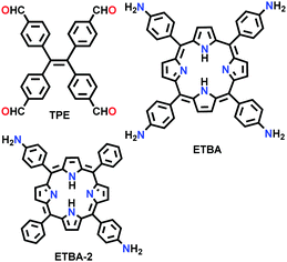
|
Solvothermal; 1,2-DCB/1-butanol/6 M AcOH (1.5![[thin space (1/6-em)]](https://www.rsc.org/images/entities/char_2009.gif) : :![[thin space (1/6-em)]](https://www.rsc.org/images/entities/char_2009.gif) 1.5 1.5![[thin space (1/6-em)]](https://www.rsc.org/images/entities/char_2009.gif) : :![[thin space (1/6-em)]](https://www.rsc.org/images/entities/char_2009.gif) 0.5); 120 °C for 3 d 0.5); 120 °C for 3 d |
sql | 250.2 (1.03) | 235 | ||
| 324.13 (1.27) | |||||||
| TAPB-DMTP-COF |
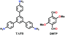
|
Solvothermal; 1,4-dioxane/butanol (v/v, 1![[thin space (1/6-em)]](https://www.rsc.org/images/entities/char_2009.gif) : :![[thin space (1/6-em)]](https://www.rsc.org/images/entities/char_2009.gif) 1); MeOH; aq. AcOH; 80 °C for 24 h 1); MeOH; aq. AcOH; 80 °C for 24 h |
hcb | 2385 | 252 | ||
| (N.R.) | |||||||
| TpBpy-COF |

|
Solvothermal; DMAc/o-DCB)/aq. AcOH; 120 °C for 72 h | hcb | 1004–1226 | 264 | ||
| (N.R.) | |||||||
| 3D cage COF-1 |
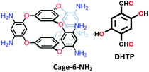
|
Solvothermal; 1,4-dioxane/AcOH/aniline; 120 °C for 72 h | acs | 1040 (0.88, 0.56) | 55 | ||
| COF-790 |
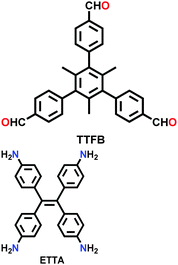
|
Solvothermal; nitrobenzene/mesitylene (3![[thin space (1/6-em)]](https://www.rsc.org/images/entities/char_2009.gif) : :![[thin space (1/6-em)]](https://www.rsc.org/images/entities/char_2009.gif) 1 v/v); 85 °C for 72 h 1 v/v); 85 °C for 72 h |
fjh | 2650 (2) | 52 | ||
| 2,3-DhaTta |
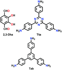
|
Solvothermal; mesitylene/1,4-dioxane/AcOH (1.7![[thin space (1/6-em)]](https://www.rsc.org/images/entities/char_2009.gif) : :![[thin space (1/6-em)]](https://www.rsc.org/images/entities/char_2009.gif) 0.3 0.3![[thin space (1/6-em)]](https://www.rsc.org/images/entities/char_2009.gif) : :![[thin space (1/6-em)]](https://www.rsc.org/images/entities/char_2009.gif) 0.2); 120 °C for 72 h 0.2); 120 °C for 72 h |
hcb | 1700 (3.537) | 79 | ||
| 2,3-DhaTab | 413 (3.536) | ||||||
| TpOMe-Pa1 |
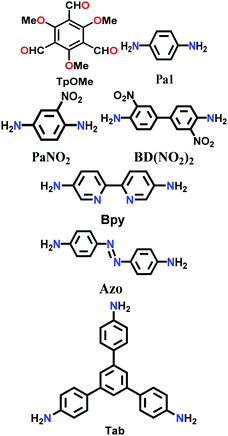
|
Solvothermal; PTSA (p-toluene sulfonic acid); 120 °C for 3 h | hcb | 1164 (1.5) | 80 | ||
| TpOMe-PaNO2 | 615 (1.4) | ||||||
| TpOMe-BD(NO2)2 | 913 (1.8) | ||||||
| TpOMe-Bpy | 2023 (2.2) | ||||||
| TpOMe-Azo | 1885 (2.8) | ||||||
| TpOMe-Tab | 593 (1.4) | ||||||
| COF-320 |
|
Solvothermal; 1,4-dioxane/3 M aq. AcOH; 120 °C for 3 d | dia | 1410 (0.85, 3.42) | 87 | ||
| CCOF-15 |
|
Solvothermal; mesitylene/n-BuOH/6M AcOH (5![[thin space (1/6-em)]](https://www.rsc.org/images/entities/char_2009.gif) : :![[thin space (1/6-em)]](https://www.rsc.org/images/entities/char_2009.gif) 5 5![[thin space (1/6-em)]](https://www.rsc.org/images/entities/char_2009.gif) : :![[thin space (1/6-em)]](https://www.rsc.org/images/entities/char_2009.gif) 1); 120 °C for 3 d 1); 120 °C for 3 d |
dia | 631 (0.8, 1.1) | 90 | ||
| CCOF-16 | 825 (1.2, 1.5) | ||||||
| TpASH COF |
|
Conventional; 4-methyl benzene sulphonic acid; Stirred at 90 °C for 12 h | hcb | 500 (1.3) | 111 | ||
| TpASH-NPHS |
|
Conventional; 4-methyl benzene sulphonic acid; Stirred at 90 °C for 12 h | hcb | ∼100 (N.R.) | 260 | ||
| TpTGx (x = Cl−, Br−, I−) |
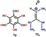
|
Solvothermal; 1,4-dioxane/water; 120 °C for 72 h | hcb | 267 (N.R.) | 114 | ||
| 305 (N.R.) | |||||||
| 298 (N.R.) | |||||||
| TFPC-NDA COF |
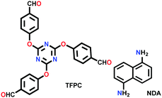
|
Solvothermal; mesitylene/THF (2![[thin space (1/6-em)]](https://www.rsc.org/images/entities/char_2009.gif) : :![[thin space (1/6-em)]](https://www.rsc.org/images/entities/char_2009.gif) 1); 100 °C for 3 d 1); 100 °C for 3 d |
hcb | 294 (0.75, 1.0, 2.1) | 24 | ||
| JUC-50x (x = 8,9) |
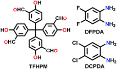
|
Solvothermal; mesitylene/1,4-dioxane/AcOH; 120 °C for 3 d | dia | 1513 (1.3) (JUC-508) | 123 | ||
| JUC-509-Y (Y = Mn, Cu, Eu) | 1443 (1.2) (JUC-509) | ||||||
| TTT-COF |
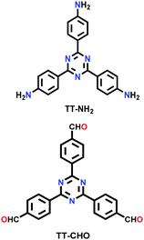
|
Solvothermal; di(n-octyl) phthalate/triphenyl phosphate (1![[thin space (1/6-em)]](https://www.rsc.org/images/entities/char_2009.gif) : :![[thin space (1/6-em)]](https://www.rsc.org/images/entities/char_2009.gif) 1 v/v); 6M aq. acetic acid; 120 °C for 72 h 1 v/v); 6M aq. acetic acid; 120 °C for 72 h |
hcb | 1431 (2.2) | 170 | ||
| TTI-COF | 1362 (2.3) | ||||||
| CON, CONN, CONNCO |
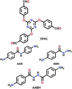
|
Solvothermal; mesitylene/1,4-dioxane/AcOH; 120 °C for 72 h | hcb | 532 (3.7) | 124 | ||
| 867 (2.9) | |||||||
| 452 (4.1) | |||||||
| TzDa-COF |
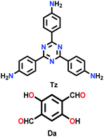
|
Solvothermal; o-DCB/DMAC/6 M aq. AcOH; 120 °C for 3 d | hcb | 709 (3.6) | 222 | ||
| COF-HQ |
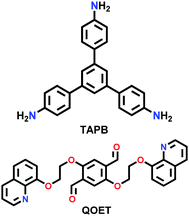
|
Solvothermal; 6 M AcOH/n-BuOH/o-DCB (1/1, v/v); 120 °C for 3 d | hcb | 302 (3.7) | 234 | ||
| TAT-COF-1 |
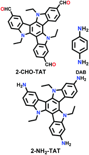
|
Solvothermal; EtOH/3 M AcOH; 90 °C for 6 d | hcb | 61.2 (N.R.) | 126 | ||
| TAT-COF-2 | 1166.1 (1.48) | ||||||
| Tx-COF-2 |
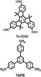
|
Solvothermal; mesitylene/1,4-dioxane/6 M aq. AcOH; 120 °C for 72 h | hcb | 1137 (2.3) | 240 | ||
| TTA-DFP COF |
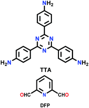
|
Solvothermal; mesitylene/1,4-dioxane/6 M aq. AcOH; 90 °C for 24 h | (N.R.) | 265 | 266 | ||
| Eu,Tb@ TTA-DFP COF | 142 (N.R.) | ||||||
| 2D-BPTA-COF |
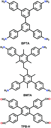
|
Solvothermal; o-DCB/n-BuOH/AcOH; 120 °C for 7 d | Rhombic kgm | 1000 (1.27) | 92 | ||
| 3D-BMTA-COF | pts | 1650 (0.85) | |||||
| 7 | Mixed imine–boroxine | NTU COF-1, NTU COF-2 |
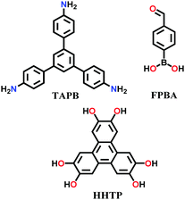
|
Solvothermal; 1,4-dioxane/mesitylene; 120 °C for 3 d | hcb | 41 (N.R.) | 64 |
| 1619 (2.5) | |||||||
| 8 | Mixed imine-β-ketoenamine | NTU-BDA-HTA (2![[thin space (1/6-em)]](https://www.rsc.org/images/entities/char_2009.gif) : :![[thin space (1/6-em)]](https://www.rsc.org/images/entities/char_2009.gif) 4), NTU-BDA-DHTA (4 4), NTU-BDA-DHTA (4![[thin space (1/6-em)]](https://www.rsc.org/images/entities/char_2009.gif) : :![[thin space (1/6-em)]](https://www.rsc.org/images/entities/char_2009.gif) 2) 2) |

|
Solvothermal; aq. AcOH/dioxane; 120 °C for 3 d | hcb | 1289.3 (1.4) | 65 |
| 1344.2 (1.4) | |||||||
| 9 | Hydrazone | COF-42 |
|
Solvothermal; mesitylene/1,4-dioxane; 120 °C for 72 h | hcb | 710 (2.3) | 22 |
| COF-43 | 620 (3.5) | ||||||
| Exfoliation of COF-43 |
|
Solvent assisted exfoliation; EtBr/K2CO3 DMF; Heating at 90 °C for 8.5 h | hcb | N.R. | 106 | ||
| Pr-COF-42 |
|
Mesitylene/1,4-dioxane/AcOH; ambient conditions for 3 d | hcb | 228 (1.8) | 129 | ||
| TFPPy-DETHz COF |
|
Solvothermal; mesitylene/1,4-dioxane; 120 °C for 72 h | sql | 1090 (2.1) | 137 | ||
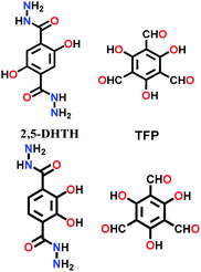
| NUS-50, NUS-51 |
|
Pestle & mortar; TFP; H2O; 90 °C for 12 h | hcb | 520 (2.56) | 130 | ||
| 510 (2.51) | |||||||
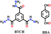
| COF-ASB |
|
Solvothermal; AcOH/DMF; 120 °C for 72 h | hcb | 357.88 (2.5) | 140 | ||
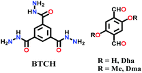
| Bth-Dha, Bth-Dma |
|
Solvothermal; mesitylene/1,4-dioxane (3![[thin space (1/6-em)]](https://www.rsc.org/images/entities/char_2009.gif) : :![[thin space (1/6-em)]](https://www.rsc.org/images/entities/char_2009.gif) 2)/Ar; 120 °C for 5 d 2)/Ar; 120 °C for 5 d |
hcb | 130 (1.9) | 141 | ||
| 392 (1.7) | |||||||
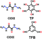
| TpODH, TFBODH |
|
Solvothermal; mesitylene/1,4-dioxane; 120 °C for 3 d | hcb | 835 (0.5–1.2) | 136 | ||
| 94 (N.R.) | |||||||
| co-COF-OH |
|
DMAc/1,2-DCB/6 M AcOH; heated in a muffle furnace at 120 °C for 72 h | hcb | 998 (2.4) | 139 | ||
| COF-DB, COF-DT |
|
Solvothermal; mesitylene/1,4-dioxane/aq. AcOH; 120 °C for 72 h | hcb | 632 (3.1) | 131 | ||
| 747 (3.1) | |||||||
| COF-Fx-H (x = 6,8,10) |
|
Solvothermal; mesitylene/1,4-dioxane/6 M AcOH; 120 °C for 3 d | hcb | 233 (1.1) | 132 | ||
| 29 (N.R.) | |||||||
| 23 (N.R.) | |||||||
| p-COF10 |
|
Solvothermal; mesitylene/1,4-dioxane/6 M AcOH; 120 °C for 3 d | hcb | 1839 (2.3) | 133 | ||
| Tfpa-Mth COF |

|
Solvothermal; mesitylene/6 M AcOH; 120 °C for 3 d | hcb | 130 (1.59, 2.7) | 134 | ||
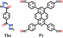
| Pythz COF |
|
Solvothermal; mesitylene/1,4-dioxane/6 M AcOH; 120 °C for 5 d | Rhombic structure of kgm | 1571 (2.34) | 138 | ||
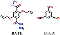
| XB COF |
|
Solvothermal; mesitylene/1,4-dioxane/6 M AcOH; 120 °C for 3 d | hcb | 365 (2.35) | 135 | ||
| PEGx-COF-42 (x = molecular wt. of polymer) |
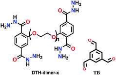
|
Interfacial layering; DTH-dimer in H2O/1,4-dioxane and TB in AcOH/mesitylene; RT for 48 h | hcb | 101 (for PEG400) and 22 (for PEG600)b | 226 | ||
| 10 | Mixed hydrazone-boroxine | COF-OEt |
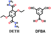
|
Solvothermal; n-BuOH/o-DCB; 150 °C for 3 d | Dual-pore hcb | 465 (2.35) | 66 |
| 11 | Aminal | AMINAL COF-1, AMINAL COF-2 |
|
Solvothermal (Under N2); For Aminal COF-1, DCl/DMSO-d6; 90 °C for 8 h. For Aminal COF-1, toluene; 120 °C for 3 d | cpi | 1169 (0.52, 0.82) | 38 |
| 1168 (0.54, 0.82) | |||||||
| PAF-6 |

|
Conventional THF/DIEA; 0 °C for 4 h; reflux at 90 °C | hcb | 182.7 (1.18) | 142 | ||
| 12 | Borazine | BLP-2(H) |
|
Solvothermal; mesitylene/toluene; 120 °C/150 mTorr for 3 d | hcb | 1178 (0.64) | 60 |
| 13 | β-Ketoenamine | TpPa-1 or TpPa-1 (MW) or TpPa-1 (MC) |

|
Solvothermal; mesitylene/1,4-dioxane; 3 M AcOH; 120 °C for 3 d | hcb | 535 (1.25) | 67 |
| Microwave-assisted; mesitylene/1,4-dioxane, 3 M AcOH; 100 °C for 1 h | hcb | 724.6 (1.27) | 84 | ||||
| Mechano-chemical grinding for 40 min | hcb | 61 (N.R.) | 83 | ||||
| DAB-TFP, DAAQ-TFP |
|
Solvothermal; 6 M AcOH/1,4-dioxane; 120 °C for 2 d | hcb | 365 (N.R.) | 143 | ||
| 435 (2.0) | |||||||
| TpTh(LAG) |

|
Liquid-assisted mechanochemical; mesitylene/1,4-dioxane; 3 M AcOH; 120 °C for 3d | hcb | ∼100 (N.R.) | 94 | ||
| TAPB-TFP, iPr-TAPB-TFP |
|
Solvothermal; 6 M AcOH/dioxane; 110 °C for 5 d | hcb | 567 (N.R.) | 145 | ||
| 756 (N.R.) | |||||||
| TpBD(NO2) |

|
Solvothermal; mesitylene/1,4-dioxane/3 M AcOH; 120 °C for 96 h | hcb | 639 (2.3, ∼1.6) | 146 | ||
| TpBD(NH2) | 643 (2.3, ∼1.6) | ||||||
| TpBD(NHCOCH3)2 | 519 (2.3, ∼1.6) | ||||||
| TP-EDDA, TP-BDDA |
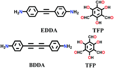
|
Solvothermal; mesitylene/1,4-dioxane/AcOH; 120 °C for 72 h, 96 h | hcb | 523 (N.R.) | 147 | ||
| 758 (N.R.) | |||||||
| 3D-TpBD-Me2 |

|
Solvothermal; mesitylene/1,4-dioxane/3 M AcOH; sonication at RT for 30 mins; 120 °C for 72 h | hcb | 1022 | 148 | ||
| JUC-52x (x = 0, 1, 2, 3) |
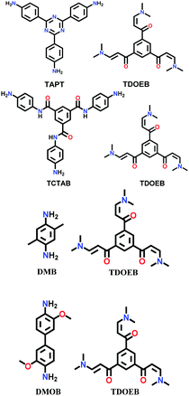
|
Room temperature synthesis; AcOH/H2O; 8 h | hcb | 976 (1.53) | 150 | ||
| 1127 (1.87) | |||||||
| 1182 (1.95) | |||||||
| 1435 (2.88) | |||||||
| COF JLU-4 |
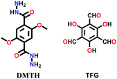
|
Solvothermal; mesitylene/1,4-dioxane (3![[thin space (1/6-em)]](https://www.rsc.org/images/entities/char_2009.gif) : :![[thin space (1/6-em)]](https://www.rsc.org/images/entities/char_2009.gif) 1 v/v)/6 M AcOH; 120 °C for 7 d 1 v/v)/6 M AcOH; 120 °C for 7 d |
hcb | 923 (2.2) | 144 | ||
| 3PD, 3BD, 3′PD, 2TPA |
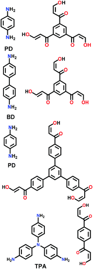
|
Solvothermal; mesitylene/1,4-dioxane/3 M AcOH; 130 °C for 3 d | hcb | 505 (1.27) | 201 | ||
| 478 (1.33) | |||||||
| 258 (3.19, 4.52) | |||||||
| 252 (9.70) | |||||||
| DAAQ-ECOF |
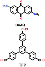
|
Solvothermal; DMAc/mesitylene; 120 °C for 3 d | hcb | 216 (N.R.) | 109 | ||
| 14 | Phenazine | CS-COF |
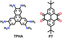
|
Solvothermal; Ethylene glycol; 3 M aq AcOH; sonication for 15 min; 120 °C for 3 d | hcb | 776 (1.6) | 151 |
| 15 | C–C coupling | 2D-CAP |
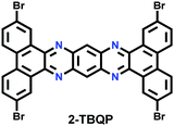
|
Surface-mediated polymerization; adsorption on Au(111); 250 °C | Rectangular grid net | 539 (N.R.) | 72 |
| 16 | Azine | Py-Azine |
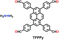
|
Solvothermal; 6 M AcOH; n-BuOH/o-DCB 120 °C for 7 d | Rhombic kgm | 1210 (1.76) | 152 |
| NUS-30 |
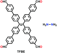
|
Solvothermal; 1,4-dioxane/6 M AcOH (10/1, v/v); 120 °C for 5 d | kgm | 1386 (0.6, 2.96) | 209 | ||
| NUS-31 | 685 (1.26, 3.05) | ||||||
| NUS-32 | 249 (3.71) | ||||||
| ACOF-1 |

|
Solvothermal; mesitylene/1,4-dioxane/6 M AcOH; 120 °C for 72 h | hcb | 1176 (0.94) | 153 | ||
| COF-JLU-3 |
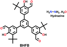
|
Solvothermal; DMF/6 M AcOH; 120 °C for 3 d | hcb | 560 (N.R.) | 245 | ||
| 17 | Imide | PI-COF-1, PI-COF-2, PI-COF-3 |
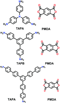
|
Solvothermal; NMP/mesitylene/isoquinoline; 200 °C or 250 °C for 5–7 d | hcb | 1027 (2.9) | 156 |
| 1297 (3.3) | |||||||
| 2346 (5.1) | |||||||
| PI-COF-4, PI-COF-5 |
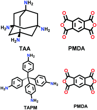
|
Solvothermal; NMP/mesitylene/Isoquinoline; 160 °C for 5 d | dia | 2403 (1.3) | 44 | ||
| 1876 (1.0) | |||||||
| 18 | Spiroborate | ICOF-1 (DMA+), ICOF-2 (Li+) |

|
Solvothermal; (CH3)2NH or LiOH; 120 °C for 7 d | fes | 1022 (1.1) | 37 |
| 1259 (2.2) | |||||||
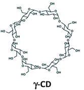
| CD-COF-Li |
|
Microwave synthesis; mesitylene/DMF; 120 °C for 4 h | rra | 760 (0.64) | 48 | ||
| CD-COF-DMA | 934 (N.R.) | ||||||
| CD-COF-PPZ | 494 (N.R.) | ||||||
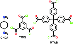
| 19 | Amide | CAF-1, CAF-2 |
|
Solvothermal; DMF; N2; NEt3; 0 °C; H2O; 10−4 mbar; 250 °C (CAF-1) 270 °C for 3 d and (CAF-2) for 7 d | hxl | 256 (N.R.) | 86 |
| dia | 354 (N.R.) | ||||||
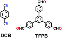
| 20 | Olefinic | 2DPPV |
|
Solvothermal; o-DCB; 150 °C for 3 d | hcb | 472 (1.6) | 158 |
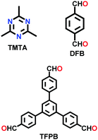
| g-C18N3, g-C33N3 |
|
Solvothermal; nBuOH/o-DCB; 120 °C for 72 h | hcb | 1170 (1.72) | 159 | ||
| 752 (1.45) | |||||||
| COF-701 |
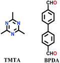
|
Solvothermal; mesitylene/dioxane/CAN;CF3COOH; 150 °C for 72 h | hcb | 1366 (1.14) | 160 | ||
| g-C34N6 |
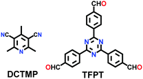
|
Solvothermal; DMF/piperidine; 180 °C for 3 d | hcb | 1003 (1.45) | 161 | ||
| TP-COF |
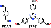
|
Solvothermal; dioxane/Cs2CO3; 120 °C for 3 d | hcb | 232 (1.2, 2.2) | 200 | ||
| TFPT-BTAN-AO |
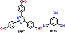
|
Solvothermal; NH2OH·HCl; o-DCB/4 M DBU (10![[thin space (1/6-em)]](https://www.rsc.org/images/entities/char_2009.gif) : :![[thin space (1/6-em)]](https://www.rsc.org/images/entities/char_2009.gif) 1 v/v); 85 °C for 24 h 1 v/v); 85 °C for 24 h |
hcb | 803 (1.26) | 256 | ||
| sp2c-COF-1, sp2c-COF-2, sp2c-COF-3 |
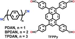
|
Solvothermal; 1,4-dioxane/KOH; 90, 110 °C for 3 d and o-DCB/MeOH; 120 °C for 3 d, respectively | sql | 613 (∼2.0) | 202 | ||
| 322 (∼2.0) | |||||||
| 737 (∼2.0) | |||||||
| 21 | Dioxin | COF-316, COF-318 |
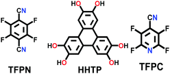
|
Solvothermal; 1,4-dioxane/Et3N; 120 °C for 3 d | hcb | 557 (1.2) | 62 |
| 576 (1.5) | |||||||
| MPc-TFPN (M = Ni/Co/Zn) |
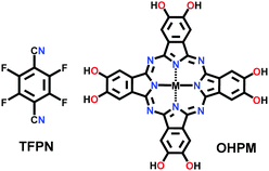
|
Solvothermal; DMAc/mesitylene/Et3N; 150 °C for 3 d | sql | 252.4 (for Ni) | 171 | ||
| ∼200 (for Co/Zn) | |||||||
| 22 | Bis(imidazole) | TpDAB |

|
Solvothermal; mesitylene/1,4-dioxane/6 M AcOH/120 °C for 72 h | (N.R.) | 319 (1.3–1.8) | 162 |
| TBICOF |
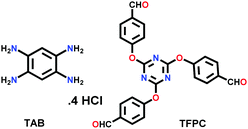
|
Solvothermal; mesitylene/NMP/dioxane; 120 °C for 3 d | hcb | 1424 (2.5) | 68 | ||
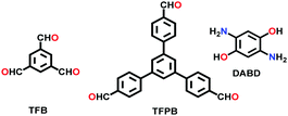
| 23 | Benzo-bis(oxazole) | BBO-COF-1, BBO-COF-2 |
|
Conventional; DMF; −15 °C; 3 h; RT; 1 eqv NaCN; 130 °C for 4 d | hcb | 891 (1.34) | 69 |
| 1106 (1.84) | |||||||
| TPT-DAHQ |
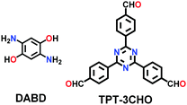
|
Solvothermal; DMF; 120 °C for 3 d | hcb | 1855 (2.3) | 164 | ||
| 24 | Squarine | CuP-SQ |
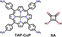
|
Solvothermal; o-DCB/n-BuOH; 85 °C for 7 d | sql | 539 (2.1) | 155 |
| 25 | Silicate | SiCOF-5 |
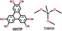
|
Solvothermal; MeOH; 180 °C for 4 d | srs | 370 (∼ 3) | 49 |
| SiCOF-Li |

|
Solvothermal; anhy. MeOH; SiO2 or TMOS; 180 °C for 4 d | hcb | 1153, 1276, 1067 (0.6, 1.35) | 165 | ||
| SiCOF–Na | |||||||
| SiCOF-K | |||||||
| 26 | Oxazole and thiazole | LZU-192 (oxazole), COF-921 (thiazole) |
|
Solvothermal; DCB/BuOH; 6 M AcOH; 120 °C for 4 d and DMF/H2O; 85 °C for 1 d | sql | 1770 (2.049) | 70 |
| 1550 (2.121) | |||||||
| 27 | Azodioxy | POR-COF |
|
Room temperature; THF; stirred for 12 h | sql | 447 (1.95) | 35 |
| NPN-1, NPN-2, NPN-3 |
|
Mesitylene/ethanol (3![[thin space (1/6-em)]](https://www.rsc.org/images/entities/char_2009.gif) : :![[thin space (1/6-em)]](https://www.rsc.org/images/entities/char_2009.gif) 2); Celite-supported Ag2CO3; stirred for 5 min at RT; left undisturbed for 48 h 2); Celite-supported Ag2CO3; stirred for 5 min at RT; left undisturbed for 48 h |
dia | (N.R.) | 88 | ||
| 28 | Urea | COF-117 |
|
Solvothermal; NMP/1,2,4-trichlorobenzene (TCB)/6 M aq. AcOH; 85 °C for 3 d | hcb | 114 | 81 |
| COF-118 | 1524 (∼2.5) | ||||||
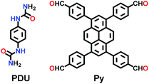
| Pyurea COF |
|
Solvothermal; 6 M AcOH/NMP; 120 °C for 5 d | Rhombic structure of kgm | 1016 (1.48) | 138 | ||
| 29 | Viologen | HS |
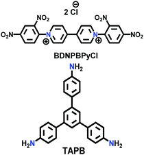
|
Solvothermal; EtOH/H2O; 120 °C for 3 d; or microwave-assisted; 2.45 GHz at 100 °C for 2 h | hcb | 12 (HS) | 166 |
| HT | 35 (HS) | ||||||
| COGF | (N.R.) | ||||||
| COP++ |
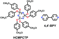
|
Microwave-assisted; ACN; 2.45 GHz; 89 °C for 1 h | (N.R.) | (N.R.) | 167 | ||
| COP-1++, COP-2++ |
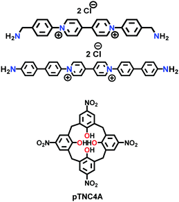
|
Solvothermal; DMF; 150 °C for 24 h | (N.R.) | 17.9 (N.R.) | 169 | ||
| 51.8 (N.R.) | |||||||
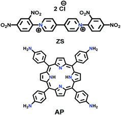
| PV-COF |
|
Microwave; EtOH/H2O; 90 °C for 2 h | sql | 38.2 (2.3) | 168 | ||
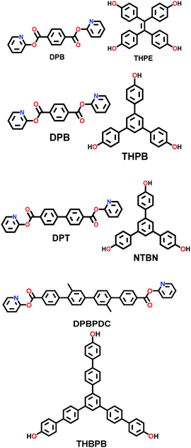
| 30 | Ester | COF-119, COF-120, COF-121, COF-122 |
|
Solvothermal; anhy. dioxane/1,8-diazabi-cyclo [5.4.0] undec-7-ene; 150 °C (COF-119 to 121) or 160 °C (COF-122) for 3 d | Kgm (for COF-119) | 2092 (2.99, 1.79) | 63 |
| hcb (for COF-120/121/122) | 1255 (2.52) | ||||||
| 908 (2.99) | |||||||
| 664 (2.272, 4.367) | |||||||
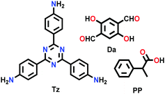
| PP-TzDa |
|
Solvothermal; THF/TEA; 60 °C; 3 d | hcb | 583 (1.7–1.8) | 265 | ||
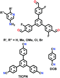
| 31 | Pyrimidazole | LZU-56x x = 1–8 |
|
Solvothermal; DCB; PTSA-H2O; EtOH/mesitylene; 120 °C for 5 d | (N.R.) | 321 (1.2) | 172 |
| 340 (1.2, 1.8) | |||||||
| 554 (1.1) | |||||||
| 540 (1.2) | |||||||
| 110 (2.7) | |||||||
| 87 (2.7) | |||||||
| 137 (2.7) | |||||||
| 400 (2.7) | |||||||
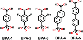
| 32 | Poly-cubane | BP-COF-1, BP-COF-2, BP-COF-3, BP-COF-4, BP-COF-5 |
|
Solvothermal; DMSO/toluene; 120 °C for 3 d (BP-COF-1 to BP-COF-3) and 100 °C for 3 d (BP-COF-4 and BP-COF-5) | bcu | 519 (0.6) | 57 |
| 485.69 (0.54) | |||||||
| 655.75 (0.58) | |||||||
| 632.08 (0.6) | |||||||
| 621.65 (0.93) | |||||||
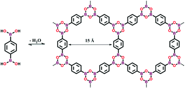 | ||
| Fig. 8 Synthesis of boroxine-linked COF-1 via the self-condensation of 1,4-benzenediboronic acid. Adapted from ref. 4, Copyright The American Association for the Advancement of Science (2005). | ||
The faster synthesis of the COF-5 powder was conducted with the microwave-assisted technique, yielding a crystalline product in 20 min at 100 °C and 200 W power.95 The resulting framework possessed a higher BET surface area (2019 m2 g−1) in comparison to that obtained via the usual solvothermal method (1590 m2 g−1).
The other covalent triazine frameworks synthesized using the ionothermal technique include FCTF-1, FCTF-1–600, m-CTF and PTF-series.120,121 The FCTF series involves the inclusion of fluorine atoms in the framework, which improved the network stability and increased the number of ultramicropores (<0.5 nm). Alternatively, the m-CTF and PTF-series were subjected to molten ZnCl2 at different temperatures, i.e., 400 °C for the m-CTF series and 550–700 °C for the PTF series, with 1,3,5-tricyanobenzene (TCB) precursor.
![[double bond, length as m-dash]](https://www.rsc.org/images/entities/b_char_e001.gif) N linkage (imine).
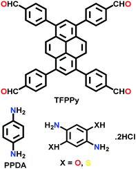
An imine bond is a dynamic covalent bond, which is usually synthesized via a reversible Schiff-base condensation reaction between amines and aldehydes. The imine-linked porous frameworks are N-rich and have higher thermal, chemical and hydrolytic (in some cases) stability compared to boron-containing frameworks. Imine-linked crystalline COF powders have been synthesized via solvothermal, mechanochemical, ionothermal and room-temperature synthesis. The first imine-linked 3D COF was formed in 2009 via the solvothermal condensation of a Td-symmetric tetra-(4-anilyl)methane (TMA) with the linear terephthaldehyde (BDA), as shown in Fig. 9a.82 Single crystals of COF-300 were obtained nine years later for structure determination by the single-crystal X-ray diffraction (SCXRD) technique (vide infra).6 The representation of COF-300 is [(TAM)(BDA)2]imine with seven-fold interpenetration. Also, the highly crystalline 2DILCOF-1 was synthesized at 120 °C via the condensation reaction between 1,3,6,8-tetrakis(p-formylphenyl)pyrene (TFPPy) and p-phenylenediamine (PDA) in 1,4-dioxane in the presence of aqueous acetic acid over 3 days (Fig. 9b).122 This COF had a larger surface area than that of the 3D imine-linked IL COF-1 (refer to Section 5.6).
N linkage (imine).
An imine bond is a dynamic covalent bond, which is usually synthesized via a reversible Schiff-base condensation reaction between amines and aldehydes. The imine-linked porous frameworks are N-rich and have higher thermal, chemical and hydrolytic (in some cases) stability compared to boron-containing frameworks. Imine-linked crystalline COF powders have been synthesized via solvothermal, mechanochemical, ionothermal and room-temperature synthesis. The first imine-linked 3D COF was formed in 2009 via the solvothermal condensation of a Td-symmetric tetra-(4-anilyl)methane (TMA) with the linear terephthaldehyde (BDA), as shown in Fig. 9a.82 Single crystals of COF-300 were obtained nine years later for structure determination by the single-crystal X-ray diffraction (SCXRD) technique (vide infra).6 The representation of COF-300 is [(TAM)(BDA)2]imine with seven-fold interpenetration. Also, the highly crystalline 2DILCOF-1 was synthesized at 120 °C via the condensation reaction between 1,3,6,8-tetrakis(p-formylphenyl)pyrene (TFPPy) and p-phenylenediamine (PDA) in 1,4-dioxane in the presence of aqueous acetic acid over 3 days (Fig. 9b).122 This COF had a larger surface area than that of the 3D imine-linked IL COF-1 (refer to Section 5.6).
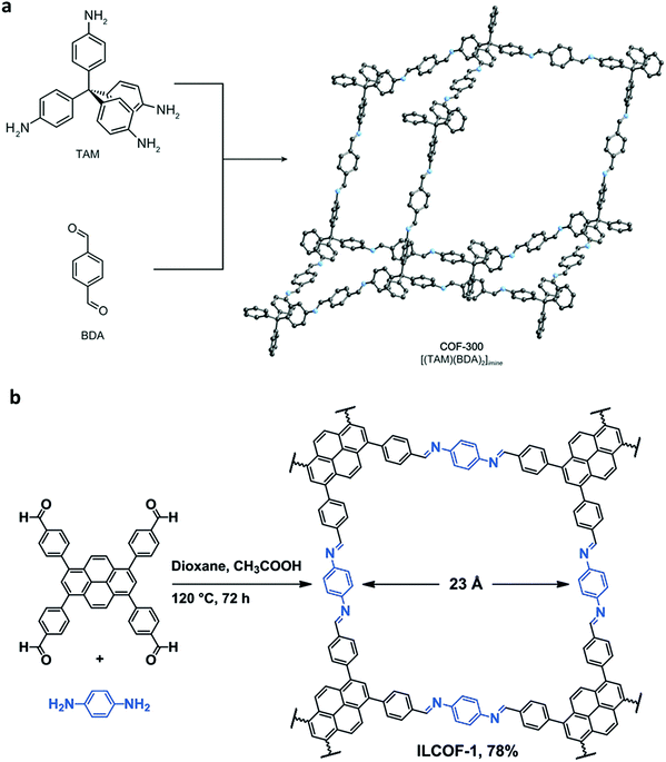 | ||
| Fig. 9 (a) Synthesis of COF-300 and (b) 2D ILCOF-1. Reproduced with permission from: (a) ref. 6, Copyright The American Association for the Advancement of Science (2018) and (b) ref. 122, Copyright John Wiley and Sons (2013). | ||
The other COF powders with imine-linkages fabricated via the solvothermal technique include TFPC-NDA COF,24 JUC-508, JUC-509, and JUC-509-Y (Y = Mn, Cu and Eu),123 and some single-crystal COFs include COF-303, LZU-79 and LZU-111 with dia and lon networks.6 The modulator-directed imine formation reaction was conducted, which increased the state of reversibility and provided a chance for error-correction. Aniline is a mono-functional molecule that hinders nucleation and promotes crystal growth. Two other single crystalline COFs, viz., COF-303 and LZU-79, were synthesized solvothermally via the reticular strategy and possessed very highly interpenetrated dia-c7 and dia-c10 topology, respectively. Alternatively, the combination of two Td-symmetric monomers tailored the LZU-111 COF with the distinct lon-b-c3 topology (vide supra, Section 2.2).
A series of unique semi-flexible and flexible imine-linked 2D COFs, namely CON, CONN and CONNCO, was solvothermally synthesized with high crystallinity and stability in water and at different pH (Fig. 10).124 The N-rich frameworks act as an efficient ON–OFF pH-responsive proton scavenger (further discussed in Section 6.2.2).
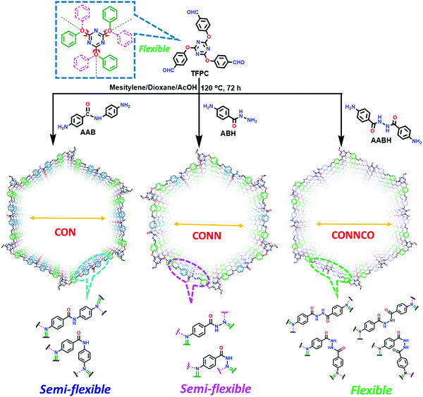 | ||
| Fig. 10 Synthesis of CON, CONN, and CONNCO from highly flexible and semi-flexible linkages. Dotted lines indicate various possible conformers due to flexibility and semi-flexibility of linkers. Reproduced with permission from ref. 124, Copyright the American Chemical Society (2021). | ||
High temperature-autogenous pressure conditions successfully worked for the synthesis of highly luminescent active, crystalline and stable COFs, namely the COF-N, COF-NN (Fig. 11a) and TAT-COF series (Fig. 11b).125,126 These 2D frameworks were well explored for the fluorescence-based detection of small volatile organic molecules.
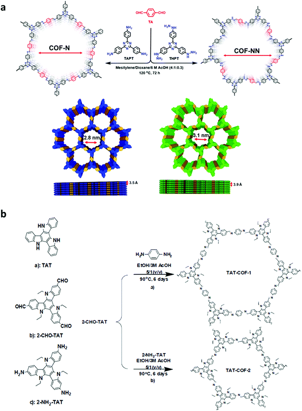 | ||
| Fig. 11 (a) Synthesis of 2D imine-linked COF-N and COF-NN. (b) Structures of TAT model compound and its aldehyde and amine derivatives and synthesis of TAT-COF-1 and TAT-COF-2. Reproduced and adapted with permission from: (a) ref. 125, Copyright the American Chemical Society (2020) and (b) ref. 126, Copyright The Royal Society of Chemistry (2015). | ||
Furthermore, several imine-linked covalent organic thin films and nanosheets have also been fabricated using the exfoliation, interfacial and continuous flow methods. Surface COFs, namely SCOF-IC1 and SCOF-LZU1101 and single-layered sCOF (A + B) and sCOF (C + D),127 were constructed via solid/vapour interfacial synthesis.
The formation of single-layered sCOF (A + B) and (C + D) requires control of the conformation of the precursor during the reaction. Highly rigid, aromatic monomers were chosen to construct single-layered films at ambient conditions, whereas more flexibility of aliphatic monomers requires ultra-high vacuum (UHV) conditions after impinging on the Au(111) surface.
A unique method of continuous flow was employed for the synthesis of COF-LZU-1 from 1,3,5-triformylbenzene (TFB) and p-phenylenediamine (PPDA).116 The stock solution of both monomers was separately formed in a mixture of dioxane and acetic acid, and then injected together in a flow reactor at a rate of 20 μL/min under ambient conditions, yielding a bright yellow product.
![[double bond, length as m-dash]](https://www.rsc.org/images/entities/b_char_e001.gif) N) linkage.
The only example in this category is TRITER-1, which was synthesized via a one-pot polycondensation reaction between 4-aminobenzonitrile and terephthalic acid in the presence of triflic acid.128 The reaction mixture was refluxed at 150 °C for 12 h in the high boiling-point solvent, DMF. Initially, the in situ synthesis of 1,3,5-tris-(4-aminophenyl)triazine (TAPT) was conducted using a nitrile-substituted unit supported by acid-catalyzed trimerization. Subsequently, it underwent a Schiff base condensation reaction, yielding mixed triazine-imine linkages. This framework is N-rich, thermally stable, and possesses a high surface area and supermicropores (1.5 nm).
N) linkage.
The only example in this category is TRITER-1, which was synthesized via a one-pot polycondensation reaction between 4-aminobenzonitrile and terephthalic acid in the presence of triflic acid.128 The reaction mixture was refluxed at 150 °C for 12 h in the high boiling-point solvent, DMF. Initially, the in situ synthesis of 1,3,5-tris-(4-aminophenyl)triazine (TAPT) was conducted using a nitrile-substituted unit supported by acid-catalyzed trimerization. Subsequently, it underwent a Schiff base condensation reaction, yielding mixed triazine-imine linkages. This framework is N-rich, thermally stable, and possesses a high surface area and supermicropores (1.5 nm).
![[double bond, length as m-dash]](https://www.rsc.org/images/entities/b_char_e001.gif) N and B–O) linkage.
Binary NTU-COF-1 and ternary NTU-COF-2 involve the formation of two types of covalent bonds (C–N and B–O).64 The orthogonal reaction strategy to construct NTU-COF-1 involves the use of 4-formylphenylboronic acid (FPBA) and 1,3,5-tris(4-aminophenyl)-benzene (TAPB). The bifunctional FPBA unit contains a boronic acid group on one end, which is easily converted into a boroxine ring under high thermal conditions, and an aldehydic group on the other end, generating an imine-linkage. Both reactions are compatible and do not interfere with each other to carry out feasible orthogonal reactions. Similarly, NTU-COF-2 utilizes three different monomers, TAPB, FPBA and HHTP, in 1,4-dioxane solvent. Therefore, solvothermal conditions are employed for the synthesis of mixed imine–boroxine linked COFs, i.e., heating at 120 °C for 72 h for both NTU-COF-1 and NTU-COF-2.
N and B–O) linkage.
Binary NTU-COF-1 and ternary NTU-COF-2 involve the formation of two types of covalent bonds (C–N and B–O).64 The orthogonal reaction strategy to construct NTU-COF-1 involves the use of 4-formylphenylboronic acid (FPBA) and 1,3,5-tris(4-aminophenyl)-benzene (TAPB). The bifunctional FPBA unit contains a boronic acid group on one end, which is easily converted into a boroxine ring under high thermal conditions, and an aldehydic group on the other end, generating an imine-linkage. Both reactions are compatible and do not interfere with each other to carry out feasible orthogonal reactions. Similarly, NTU-COF-2 utilizes three different monomers, TAPB, FPBA and HHTP, in 1,4-dioxane solvent. Therefore, solvothermal conditions are employed for the synthesis of mixed imine–boroxine linked COFs, i.e., heating at 120 °C for 72 h for both NTU-COF-1 and NTU-COF-2.
![[double bond, length as m-dash]](https://www.rsc.org/images/entities/b_char_e001.gif) N–NH2) linkage.
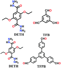
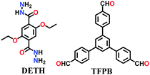
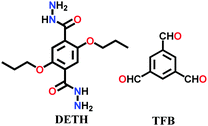
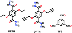
A large number of covalently-bonded frameworks with hydrazone-linked monomeric units has been reported thus far. These frameworks are either formed as crystalline bulk powders and/or few-layered thin films. The first hydrazone-linked COFs were reported in 2011, which are mesoporous crystalline COF-42 and COF-43 constructed by the reversible dehydration reaction of 2,5-diethoxyterephthalohydrazide (DETH) and 1,3,5-triformylbenzene (TFB) or 1,3,5-tris(4-formylphenyl)benzene (TFPB) in the presence aqueous acetic acid and a mesitylene/1,4-dioxane mixture in a flame-sealed tube at 120 °C for 72 h, respectively.22 Both COFs were collected as a pale-yellow microcrystalline powder. The few-layered COF-43 was obtained one year later by employing the solvent-assisted exfoliation technique and solid/vapour interfacial method.106 The appropriate choice of solvent yields COF-layered sheets with high aspect ratios. In addition to solvothermal conditions, the room-temperature synthesis of COF-42, COF-43 and Pr-COF-42 was performed in 2017 with the same monomers, DETH (propyl substituted for Pr-COF-42) and TFB.129 The monomers were suspended in a 1,4-dioxane/mesitylene mixture in the presence of 6 M aq AcOH catalyst and then left undisturbed for 3 days. Highly crystalline frameworks were obtained, particularly COF-42 with 72% yield, which was found to be comparable to that synthesized under solvothermal conditions.
N–NH2) linkage.
A large number of covalently-bonded frameworks with hydrazone-linked monomeric units has been reported thus far. These frameworks are either formed as crystalline bulk powders and/or few-layered thin films. The first hydrazone-linked COFs were reported in 2011, which are mesoporous crystalline COF-42 and COF-43 constructed by the reversible dehydration reaction of 2,5-diethoxyterephthalohydrazide (DETH) and 1,3,5-triformylbenzene (TFB) or 1,3,5-tris(4-formylphenyl)benzene (TFPB) in the presence aqueous acetic acid and a mesitylene/1,4-dioxane mixture in a flame-sealed tube at 120 °C for 72 h, respectively.22 Both COFs were collected as a pale-yellow microcrystalline powder. The few-layered COF-43 was obtained one year later by employing the solvent-assisted exfoliation technique and solid/vapour interfacial method.106 The appropriate choice of solvent yields COF-layered sheets with high aspect ratios. In addition to solvothermal conditions, the room-temperature synthesis of COF-42, COF-43 and Pr-COF-42 was performed in 2017 with the same monomers, DETH (propyl substituted for Pr-COF-42) and TFB.129 The monomers were suspended in a 1,4-dioxane/mesitylene mixture in the presence of 6 M aq AcOH catalyst and then left undisturbed for 3 days. Highly crystalline frameworks were obtained, particularly COF-42 with 72% yield, which was found to be comparable to that synthesized under solvothermal conditions.
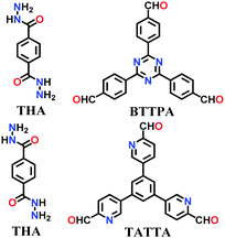
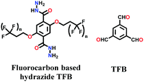
Lately, various other COFs have been fabricated with the hydrazone linkage using the solvothermal technique, such as NUS-50,130 NUS-51,130 COF-DB,131 COF-DT,131 COF-Fx-H,132p-COF10,133 TFPA-Mth COF,134 and XB-COF,135 all of which are made from ditopic aromatic hydrazine and tritopic aldehydic units. Although the synthesis of the two hydrazone-based COFs, NUS-50 and NUS-51 (NUS = National University of Singapore), involved the use of water as the solvent, the products were obtained in good yields and high purity, exemplifying the good use of water in place of toxic organic solvents. The incorporation of Co(II) in these COFs resulted in good Lewis acid catalytic activity. The stable and fluorescent active TFPA-Mth COF was prepared via the Schiff-base solvothermal condensation of tris-(4-formylphenyl) amine (Tfpa) with a hydrazide-based chiral monomer (Mth) at 120 °C for 72 h. The two above-mentioned COFs were proven to be potential candidates for metal ion sensing (vide infra). In addition, flexible dihydrazine units have been used together with a trialdehyde monomer to give TpODH and TFPODH COFs via the imine condensation of oxalyldihydrazide (ODH) and 1,3,5-triformylphloroglucinol (Tp) or 1,3,5-triformylbenzene (TFB) at 120 °C for 72 h, respectively.136
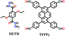
Alternatively, the combination of a ditopic aromatic hydrazine with a tetratopic pyrene-based aldehydic unit under solvothermal conditions afforded TFPPy-DETHz COF in 2018 and Pythz-COF in 2021. The TFPPy-DETHz COF was obtained in 86% via the condensation reaction of 1,3,6,8-tetrakis(4-formylphenyl)pyrene (TFPPy) and 2,5-diethoxyterephthalohydrazide (DETH) in a mixture of mesitylene and dioxane with acetic acid at 120 °C for 72 h.137 Usually COFs having a hydrazone linkages display poor luminescence behavior (similar to an imine linkage) given that the N-atoms of the linkage cause fluorescence quenching. However, scissoring the N–H bond in the N-site of the hydrazone moiety generates an N− anion, which shows improved light-emitting activity. Another pyrene-based COF, Pythz-COF, possesses high surface area and good crystallinity and exhibits excellent water sensing and adsorption behavior.138 To synthesize Pythz-COF, a Pyrex tube charged with 1,3,6, 8-tetrakis(p-formylphenyl)pyrene (Py) and terephthalic dihydrazide in a mixture of mesitylene/dioxane (2![[thin space (1/6-em)]](https://www.rsc.org/images/entities/char_2009.gif) :
:![[thin space (1/6-em)]](https://www.rsc.org/images/entities/char_2009.gif) 1, v/v) with acetic acid as a catalyst was sonicated for 10 min, degassed, and then sealed under vacuum and heated at 120 °C for 5 d.
1, v/v) with acetic acid as a catalyst was sonicated for 10 min, degassed, and then sealed under vacuum and heated at 120 °C for 5 d.
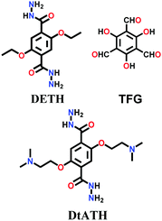
In 2019, the mixed linkers amine-co-COF-OH and amine-co-COF-H were tailored with different amounts of 2,5-bis(2-(dimethylamino)ethoxy)-terephthalohydrazide (DtATH) with DETH and trialdehydes TFG/TFB, respectively.139 The synthesis was conducted under solvothermal conditions at 120 °C for 72 h, yielding amine-rich frameworks for CO2 sorption studies. It was found that with an increase in the content of the amine-functionalized monomer DtATH, the BET surface area of both COFs was reduced by more than 50%, leading to a decrease in their CO2 uptake capacity.
A few other hydrazone-linked COFs have been reported combining trihydrazine units with dialdehyde monomers, i.e., COF-ASB, Bth-Dha and Bth-Dma. The usual solvothermal condensation was employed for their synthesis, where the monomers of both the frameworks were heated at 120 °C for 3–5 days. The highly crystalline COF-ASB was prepared via the reaction between benzene-1,3,5-tricarbohydrazide (BTCH) and benzene-1,4-dicarboxaldehyde (BDA) for 3 d.140 The COF possesses high thermal and chemical stability. Its composite with Ru nanoparticles (Ru@COF-ASB) promotes the synthesis of imines from amines and alcohols in solvent-free aerobic conditions.
Two other thermally and chemically stable COFs, Bth-Dha and Bth-Dma, were synthesized via the reaction between benzene-1,3,5-tricarbohydrazide (Bth) and 2,5-dihydroxyterephthalaldehyde (Dha) or 2,5-dimethoxyterephthaldehyde (Dma), respectively, for 5 d.141 Bth-Dma COF contains O,N,O′-chelating sites, which tend to bind Fe(III) ions selectively, acting as a potent sensor.
![[double bond, length as m-dash]](https://www.rsc.org/images/entities/b_char_e001.gif) N–NH2, B–O) linkage.
A rare example in this category is the dual-pore COF-OEt, which was solvothermally fabricated using 3,5-diformylphenylboronic acid (DFPBA) and 2,5- diethoxyterephthalohydrazide (DETH) monomers.66 At elevated temperature, the boronic acid condensed to form a boroxine ring with the simultaneous formation of the hydrazone linkage. The framework was then subjected to hydrolysis to synthesize nanotubes with free –OH groups.
N–NH2, B–O) linkage.
A rare example in this category is the dual-pore COF-OEt, which was solvothermally fabricated using 3,5-diformylphenylboronic acid (DFPBA) and 2,5- diethoxyterephthalohydrazide (DETH) monomers.66 At elevated temperature, the boronic acid condensed to form a boroxine ring with the simultaneous formation of the hydrazone linkage. The framework was then subjected to hydrolysis to synthesize nanotubes with free –OH groups.
![[double bond, length as m-dash]](https://www.rsc.org/images/entities/b_char_e001.gif) O, –NH2) linkage.
The COF chemistry that combine reversible and irreversible reactions involves the formation of a β-ketoenamine linkage. Solvothermal conditions were employed with the monomers 1,3,5- triformylphloroglucinol (Tp) and p-phenylenediamine (Pa-1) or 2,5-dimethyl-p-phenylenediamine (Pa-2) to yield TpPa-1 and TpPa-2 COF powders, respectively.67 A well-sonicated concoction of monomers in dioxane/mesitylene was added to a Pyrex tube and subjected to prolonged heating at 120 °C for 72 h. The detailed chemistry and stability aspects of TpPa-1 are mentioned in Section 3.1. Similarly, the 2D DAAQ-TFP COF was tailored using 2,6-diaminoanthraquinone (DAAQ) and 1,3,5-triformylphloroglucinol (TFP) monomers in two different solvents, i.e., 1,4-dioxane and N,N-dimethylacetamide.143 The reaction temperature of the glass ampoule containing the reaction mixtures varied with the choice of solvent, i.e., dioxane-solvated mixture was heated at 120 °C, yielding ∼60–70% product, while that with DMA was carried out at 90 °C for 2 days, yielding ∼70–85% product.
O, –NH2) linkage.
The COF chemistry that combine reversible and irreversible reactions involves the formation of a β-ketoenamine linkage. Solvothermal conditions were employed with the monomers 1,3,5- triformylphloroglucinol (Tp) and p-phenylenediamine (Pa-1) or 2,5-dimethyl-p-phenylenediamine (Pa-2) to yield TpPa-1 and TpPa-2 COF powders, respectively.67 A well-sonicated concoction of monomers in dioxane/mesitylene was added to a Pyrex tube and subjected to prolonged heating at 120 °C for 72 h. The detailed chemistry and stability aspects of TpPa-1 are mentioned in Section 3.1. Similarly, the 2D DAAQ-TFP COF was tailored using 2,6-diaminoanthraquinone (DAAQ) and 1,3,5-triformylphloroglucinol (TFP) monomers in two different solvents, i.e., 1,4-dioxane and N,N-dimethylacetamide.143 The reaction temperature of the glass ampoule containing the reaction mixtures varied with the choice of solvent, i.e., dioxane-solvated mixture was heated at 120 °C, yielding ∼60–70% product, while that with DMA was carried out at 90 °C for 2 days, yielding ∼70–85% product.
In 2016, the highly luminescent and semi-flexible COF-JLU4 was reported from the solvothermal condensation of 2,5-dimethoxyterephthalohydrazide with triformylphloroglucinol (Fig. 12).144 The COF initially forms hydrazone bonding with further bonding in the β-ketoenamine linkage due to the hydroxyl-substituted trialdehyde group. The N-rich framework possessed exceptional chemical and moisture stability and was the first to be utilized as an efficient pH sensor (Section 6.2.2).
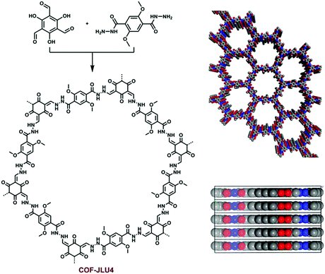 | ||
| Fig. 12 Synthesis of β-ketoenamine-based COF-JLU4 and its structural packing. Reproduced with permission from ref. 144, Copyright The Royal Society of Chemistry (2016). | ||
Likewise, many β-ketoenamine-linked frameworks have been constructed using high temperature-autogenous pressure conditions, such as, TAPB-TFP COF, iPr-TAPB-TFP COF,145 nitro-substituted TpBD(NO2) COF,146 highly unsaturated TP-EDDA and TP-BDDA COFs,147 and methyl substituted 3D-TpBD-Me2 COF.148 The synthesis of these COFs involves the use of a solvent combination of 1,4-dioxane/mesitylene with a catalytic amount of AcOH in the temperature range of ∼110–120 °C for 72–96 h.
As shown in Fig. 13, Das et al. reported the construction of two COFs, TpBDH and TfpBDH, via the solvothermal reaction of 1,3,5-triformylphloroglucinol (Tp) and 1,3,5-tris(4-formylphenyl)benzene (Tfp), respectively, with pyromellitic-N,N′-bisaminoimide (BDH).149 These COFs show moderate chemosensor ability due to their π-stacked 2D layers, which leads to poor electron mobility and unavailability of space for the guest analytes to interact. Thus, nanosheets of TpBDH and TfpBDH CONs were obtained by exfoliating the respective bulk powders in the liquid phase using isopropyl alcohol at room temperature. AFM analysis confirmed the thickness of the nanosheets of ∼1.5–5.1 nm with ∼5–15 layers stacked together (see Section 5.4.3). Consequently, the BET surface areas of TpBDH and TfpBDH-COFs to CONs were reduced from 642 and 738 to 270 and 112 m2 g−1, respectively. The two CONs exhibit a rare turn-on explosive sensing capability in comparison to their bulk materials (see Section 6.2.1).
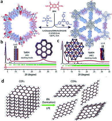 | ||
| Fig. 13 (a) Schematic representation of the synthesis of TpBDH and TfpBDH [one unit of the space filling model of TpBDH and TfpBDH is shown in the inset of the chemical drawing model]. (b and c) Experimental PXRD patterns (blue) compared with simulated pattern (eclipsed; black) and Pawley refined difference between experimental and calculated data (red) [inset models show the eclipsed AA and staggered ABC stacking of consecutive 2D layers of TpBDH and TfpBDH, respectively]. (d) Schematic representation of COFs to CONs formation. Reproduced with permission from ref. 149, Copyright The Royal Society of Chemistry (2015). | ||
The rapid, solvent-free, room temperature synthesis of TpPa-1 (MC), TpPa-2 (MC) and TpBD (MC) COFs was performed via the mechanochemical (MC) grinding method. The monomers 1,3,5-triformylphloroglucinol (Tp) and p-phenylenediamine (Pa-1), 2,5-dimethyl-p-phenylenediamine (Pa-2), or benzidine (BD) were placed in a mortar and finely ground with a pestle for 40–45 min.83 A visible color change was observed at the time intervals of 5, 15 and 40 min, showing light-yellow, bright orange and dark-red colors, indicating extended π-conjugation, respectively (Section 6.1.1).
A hydrazone-linked TpTh COF underwent β-ketoenamine formation by using 1,3,5-triformylphloroglucinol (Tp) and terephthalic dihydrazide (Th) via enol-to-keto tautomerism under LAG conditions.94 The monomers, solvent mixture (1,4-dioxane and mesitylene) and 3 M AcOH catalyst were placed in a stainless steel jar with a 7 mm steel ball and milled for 90 min. A yellow powder with high crystallinity and stability was obtained in ∼78% yield.
A distinct method for the construction of highly crystalline micro and mesoporous COFs was performed using the Michael addition-elimination reaction in the aqueous phase under ambient conditions. The JUC-52x (JUC = Jilin University China, x = 0–3) COF series with a pore size in the range of 1.59–2.92 nm was constructed.150 In a typical synthesis, a C3-symmetric 1,3,5-tris(3-dimethylamino-1-oxoprop-2-en-yl)benzene (TDOEB) unit was combined with four different amines, two of which are C3-symmetric 1,3,5-tris(4-aminophenyl)triazine (TAPT) and 1,3,5-tricarboxylic acid-tris(4-amino-phenyl-amide)benzene (TCTAB) and the other two are C2-symmetric linkers, 2,5-dimethyl-1,4-benzenediamine (DMB) and 3,30-dimethoxybenzidine (DMOB). The by-product of the reaction is dimethylamine, which further reacts with acetic acid used in the reaction to give dimethylamine acetate and dimethylacetamide, benefitting the formation of COFs with high crystallinity, porosity at high reaction rate (30 min), good yields (∼93%) and scalable capability (up to 5.0 g). Furthermore, the Fe(II)-loaded JUC-521 was efficiently exploited for the degradation of toxic pollutants in aqueous medium using the Fenton reaction.
![[double bond, length as m-dash]](https://www.rsc.org/images/entities/b_char_e001.gif) N, C
N, C![[double bond, length as m-dash]](https://www.rsc.org/images/entities/b_char_e001.gif) O) linkage.
The synthesis of COFs with mixed imine-β-ketoenamine linkages requires solvothermal conditions to form reversible Schiff bases and irreversible tautomerism, giving a β-ketoenamine linkage. Last year, three different COFs, namely NTU-BDA-HTA, NTU-BDA-DHTA, and NTU-BDA-THTA, were formed, which differ from each other in the linkage ratio due to different number of hydroxyl groups in the trialdehyde monomer unit.65 The first two COFs, as their name suggest, use mono- and di-hydroxy benzene-1,3,5-tricarbaldehyde (HTA and DHTA), which form an imine to β-ketoenamine ratio of 4
O) linkage.
The synthesis of COFs with mixed imine-β-ketoenamine linkages requires solvothermal conditions to form reversible Schiff bases and irreversible tautomerism, giving a β-ketoenamine linkage. Last year, three different COFs, namely NTU-BDA-HTA, NTU-BDA-DHTA, and NTU-BDA-THTA, were formed, which differ from each other in the linkage ratio due to different number of hydroxyl groups in the trialdehyde monomer unit.65 The first two COFs, as their name suggest, use mono- and di-hydroxy benzene-1,3,5-tricarbaldehyde (HTA and DHTA), which form an imine to β-ketoenamine ratio of 4![[thin space (1/6-em)]](https://www.rsc.org/images/entities/char_2009.gif) :
:![[thin space (1/6-em)]](https://www.rsc.org/images/entities/char_2009.gif) 2 and 2
2 and 2![[thin space (1/6-em)]](https://www.rsc.org/images/entities/char_2009.gif) :
:![[thin space (1/6-em)]](https://www.rsc.org/images/entities/char_2009.gif) 4, respectively. In contrast, the third COF, viz. NTU-BDA-DHTA, uses tri-hydroxy benzene-1,3,5-tricarbaldehyde (THTA) with benzene-1,4-diamine (BDA) having only β-ketoenamine linkages (linkage ratio = 0
4, respectively. In contrast, the third COF, viz. NTU-BDA-DHTA, uses tri-hydroxy benzene-1,3,5-tricarbaldehyde (THTA) with benzene-1,4-diamine (BDA) having only β-ketoenamine linkages (linkage ratio = 0![[thin space (1/6-em)]](https://www.rsc.org/images/entities/char_2009.gif) :
:![[thin space (1/6-em)]](https://www.rsc.org/images/entities/char_2009.gif) 6). Facilitating the framework with more stable β-ketoenamine linkages enhances the COF stability and makes the framework efficient for photocatalytic activity.
6). Facilitating the framework with more stable β-ketoenamine linkages enhances the COF stability and makes the framework efficient for photocatalytic activity.
Recently, using the solvothermal approach, a highly luminescent azine-linked framework, namely ANCOF, was constructed from tri(4-formylphenoxy)cyanurate (TFPC) and hydrazine monohydrate (Fig. 14).154 The framework is rich in nitrogen and with a high π-electron density to detect some electron-deficient species (vide infra).
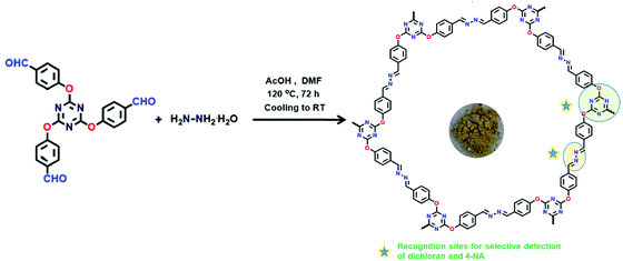 | ||
| Fig. 14 Synthesis of azine-linked ANCOF, where the star marks represent the recognition sites for the selective detection of DCNA and 4-NA. Reproduced with permission from ref. 154, Copyright the American Chemical Society (2020). | ||
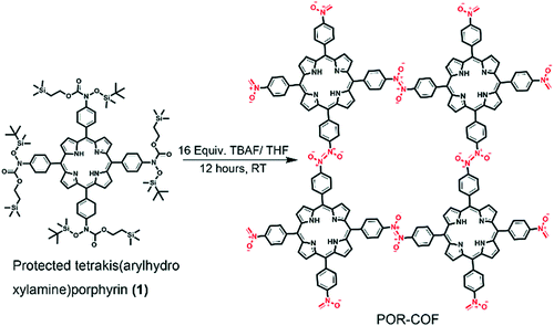 | ||
| Fig. 15 Synthesis of azodioxy-linked porphyrin-based covalent organic framework (POR-COF). Reproduced with permission from ref. 35, Copyright The Royal Society of Chemistry (2016). | ||
![[double bond, length as m-dash]](https://www.rsc.org/images/entities/b_char_e001.gif) C–) linkage.
An olefin-linked 2D conjugated COF, namely 2DPPV, was synthesized by the Knoevenagel polycondensation reaction of 1,3,5-tris(4-formylphenyl)benzene (TFPB) and 1,4-phenylene diacetonitrile (DCB) in a sealed Pyrex tube containing Cs2CO3 and o-dichlorobenzene and heated at 150 °C for 72 h.158 Recently, two triazine-cored unsubstituted olefinic-linked COFs, g-C18N3-COF and g-C33N3-COF, were synthesized via the solvothermal reaction of 2,4,6-trimethyl-1,3,5-triazine (TMTA) with a C2-symmetric linear aldehyde monomer, 1,4-diformylbenzene (DFB), and C3-symmetric trigonal aldehyde precursor, 1,3,5-tris(4-formylphenyl)-benzene (TFPB), respectively, at 120 °C for 2 h.159 The solvent combination of o-dichlorobenzene/n-butanol was employed for both frameworks with KOH and EtONa reagents in the respective mixtures. A very common honeycomb topology is knitted for both the COFs. Similarly, solvothermal conditions were used to construct olefinic-bonded COF-701160via the aldol condensation of 2,4,6-trimethyl-1,3,5-triazine (TMT) and 4,4′-biphenyldicarbaldehyde (BPDA) and g-C34N6-COF161via the Knoevenagel condensation of 3,5-dicyano-2,4,6-trimethylpyridine and 1,3,5-tris-(4-formyl-phenyl)triazine.
C–) linkage.
An olefin-linked 2D conjugated COF, namely 2DPPV, was synthesized by the Knoevenagel polycondensation reaction of 1,3,5-tris(4-formylphenyl)benzene (TFPB) and 1,4-phenylene diacetonitrile (DCB) in a sealed Pyrex tube containing Cs2CO3 and o-dichlorobenzene and heated at 150 °C for 72 h.158 Recently, two triazine-cored unsubstituted olefinic-linked COFs, g-C18N3-COF and g-C33N3-COF, were synthesized via the solvothermal reaction of 2,4,6-trimethyl-1,3,5-triazine (TMTA) with a C2-symmetric linear aldehyde monomer, 1,4-diformylbenzene (DFB), and C3-symmetric trigonal aldehyde precursor, 1,3,5-tris(4-formylphenyl)-benzene (TFPB), respectively, at 120 °C for 2 h.159 The solvent combination of o-dichlorobenzene/n-butanol was employed for both frameworks with KOH and EtONa reagents in the respective mixtures. A very common honeycomb topology is knitted for both the COFs. Similarly, solvothermal conditions were used to construct olefinic-bonded COF-701160via the aldol condensation of 2,4,6-trimethyl-1,3,5-triazine (TMT) and 4,4′-biphenyldicarbaldehyde (BPDA) and g-C34N6-COF161via the Knoevenagel condensation of 3,5-dicyano-2,4,6-trimethylpyridine and 1,3,5-tris-(4-formyl-phenyl)triazine.
![[double bond, length as m-dash]](https://www.rsc.org/images/entities/b_char_e001.gif) O) linkage.
Two polyamide-based COFs, CAF-1 and CAF-2, were synthesized under very harsh solvothermal conditions via the devitrification method (Section 3.2.2).86 The amorphous monomers, polyamide(1,3,5-tricarboxybenzene-net-trans-1,4-cyclohexanediamine) (PATnC) (for CAF-1) and polyamide(4,4′,4′′,4′′′-tetra(carboxyphenyl) methane-net-trans-1,4-cyclohexanediamine)(PATCnC) (for CAF-2), were dried under vacuum to remove the moisture content and kept at 250 °C in a pressure reactor for 3 d (CAF-1), and 240 °C in an oven for 7 d (CAF-2).
O) linkage.
Two polyamide-based COFs, CAF-1 and CAF-2, were synthesized under very harsh solvothermal conditions via the devitrification method (Section 3.2.2).86 The amorphous monomers, polyamide(1,3,5-tricarboxybenzene-net-trans-1,4-cyclohexanediamine) (PATnC) (for CAF-1) and polyamide(4,4′,4′′,4′′′-tetra(carboxyphenyl) methane-net-trans-1,4-cyclohexanediamine)(PATCnC) (for CAF-2), were dried under vacuum to remove the moisture content and kept at 250 °C in a pressure reactor for 3 d (CAF-1), and 240 °C in an oven for 7 d (CAF-2).
![[thin space (1/6-em)]](https://www.rsc.org/images/entities/char_2009.gif) :
:![[thin space (1/6-em)]](https://www.rsc.org/images/entities/char_2009.gif) 1) and dioxane, respectively, by employing the solvothermal method for 3 d or using the microwave technique for 2 h. In addition, a free-standing crystalline covalent organic gel framework (COGF) was made in a mixture of ethanol and water via microwave irradiation. The formation of hollow spheres and tubes was confirmed and observed using various microscopic characterization techniques (vide infra).
1) and dioxane, respectively, by employing the solvothermal method for 3 d or using the microwave technique for 2 h. In addition, a free-standing crystalline covalent organic gel framework (COGF) was made in a mixture of ethanol and water via microwave irradiation. The formation of hollow spheres and tubes was confirmed and observed using various microscopic characterization techniques (vide infra).
In another viologen-linked dicationic-COF, COP++, the hexatopic cyclophosphazene core was combined with CH3CN under the microwave-assisted Menshutkin reaction.167 This framework was well exploited for the adsorption of dyes with varying polarities. The polarity of COP++ was varied by reducing it from the dicationic form to the radical cationic form (COP˙+), both of which are hydrophilic and match the polarities of fluorescein (neutral) and rhodamine B (cationic) dyes. However, COP++ adsorbs fluorescein dye more selectively by up to 90%. The neutral framework COP0 exhibits a hydrophobic nature and efficiently adsorbs Nile red up to 85%.
Two porphyrin-based viologen-linked COFs, Zn-PV-COF and Red-PV-COF, were synthesized under microwave conditions, heating at 90 °C for 2 h.168 The Zincke reaction occurs between the amino-derivative of porphyrin and Zincke salt in an ethanol/water solvent mixture to give PV-COF. This COF was further metallated with zinc ions in a methanol/chloroform mixture at 50 °C for 24 h to yield Zn-PV-COF. Conversely, neutral Red-PV-COF was obtained via the stirring of PV-COF at room temperature for 15 min, where its bipyridinium units were chemically reduced using cobaltocene. The azo-bridged viologen- and calix[4]arene-based cationic covalent organic polymers (COPs) denoted as COP1++ and COP2++, respectively, were prepared by the formation of a diazo linkage between a nitro derivative of calix[4]arene (pTNC4A) and two different viologen-containing diamines in the presence of a strong base in a Schlenk tube at 150 °C for 1 d.169
![[thin space (1/6-em)]](https://www.rsc.org/images/entities/char_2009.gif) :
:![[thin space (1/6-em)]](https://www.rsc.org/images/entities/char_2009.gif) 25 at 85 °C for 1 day, and for LZU-192
25 at 85 °C for 1 day, and for LZU-192![[thin space (1/6-em)]](https://www.rsc.org/images/entities/char_2009.gif) :
:![[thin space (1/6-em)]](https://www.rsc.org/images/entities/char_2009.gif) 85
85![[thin space (1/6-em)]](https://www.rsc.org/images/entities/char_2009.gif) :
:![[thin space (1/6-em)]](https://www.rsc.org/images/entities/char_2009.gif) 15 DMF/water at 85 °C for 2 days.70 The frameworks are rich in N, O and S-heteroatoms, rigid and exhibit enhanced thermal, chemical stability under harsh acidic and basic conditions. Another thiazole-linked TTT COF was synthesized using post-synthetic locking of an imine-linked TTI-COF under very harsh thermal conditions.170 The activated TTI-COF and molten sulphur (S8) were heated at 155 °C for 3 h. The reaction mixture was well-mixed given that sulphur attains minimum viscosity at this temperature. Subsequently, the harsh thermal environment of 350 °C was provided for another 3 h, and then the mixture was left to cool to room temperature. The extra sulphur was removed by Soxhlet extraction with a toluene/THF mixture for 24 h. The imine bond locking by thiazole-ring formation enhanced the stability and robustness in the framework.
15 DMF/water at 85 °C for 2 days.70 The frameworks are rich in N, O and S-heteroatoms, rigid and exhibit enhanced thermal, chemical stability under harsh acidic and basic conditions. Another thiazole-linked TTT COF was synthesized using post-synthetic locking of an imine-linked TTI-COF under very harsh thermal conditions.170 The activated TTI-COF and molten sulphur (S8) were heated at 155 °C for 3 h. The reaction mixture was well-mixed given that sulphur attains minimum viscosity at this temperature. Subsequently, the harsh thermal environment of 350 °C was provided for another 3 h, and then the mixture was left to cool to room temperature. The extra sulphur was removed by Soxhlet extraction with a toluene/THF mixture for 24 h. The imine bond locking by thiazole-ring formation enhanced the stability and robustness in the framework.
This year, harsher conditions with prolonged time were employed for the synthesis of a urea-linked Pyurea COF.138 The monomers 1,4-phenylenediurea and 1,3,6, 8-tetrakis(p-formylphenyl)pyrene (Py) were taken in a Pyrex tube with NMP/AcOH (6M) in a ratio of 1![[thin space (1/6-em)]](https://www.rsc.org/images/entities/char_2009.gif) :
:![[thin space (1/6-em)]](https://www.rsc.org/images/entities/char_2009.gif) 0.1 and sonicated for 10 min, degassed, and then sealed under vacuum and heated at 120 °C for 5 d.
0.1 and sonicated for 10 min, degassed, and then sealed under vacuum and heated at 120 °C for 5 d.
Later, the microwave-assisted nucleophilic substitution reaction was also employed to synthesize COF-318 (here, named TH-COF).96 Both monomers, HHTP and TFPC, were placed in an ampoule and sealed with a solvent mixture of dioxane/mesitylene/triethylamine and treated with microwave heating at 70 °C for 30 min, giving 71% yield. Its surface area of 1254 m2 g−1 is much higher than that synthesized under solvothermal conditions (576 m2 g−1).
A series of dioxin-linked metallophthalocyanine COFs, MPc-TFPN COF (M = Ni, Co, and Zn), was prepared using reticular chemistry.171 The Et3N-catalysed nucleophilic substitution reaction occurs between 2,3,9,10,16,17,23,24-octahydroxyphthalo -cyaninato metal (MPc-8OH; M = Ni, Co, and Zn) and tetrafluorophthalonitrile (TFPN) in DMA/mesitylene placed at 150 °C for 3 d. The framework possesses high thermal stability (∼400 in N2 and ∼300 in O2 environment) and chemical stability (in common organic solvents and conc. acid/base conditions), which are attributed to the rigid metalophthalocyanine units.
![[double bond, length as m-dash]](https://www.rsc.org/images/entities/b_char_e001.gif) C–O–) linkage.
An ester is a rarely exploited linkage in COF chemistry. A solvothermal synthetic method was used to construct a series of ester-linked COFs, COF-119, COF-120,COF-121 and COF-122.63 Here, the trans-esterification reaction takes place between the hydroxyl-functionalised tri- or tetratopic units and ditopic 2-pyridinyl aromatic carboxylates. The reaction between di(pyridin-2-yl) terephthalate (DPT) and tetrakis(4-hydroxyphenyl)ethylene (THPE) or 1,3,5-tris(4-hydroxyphenyl)benzene (THPB) yields COF-119 with the kgm topology and COF-120 with hcb topology, respectively, in the presence of DBU/dioxane at 150 °C for 3 d. Furthermore, the reticulated COF-121 was obtained by reacting THPB with di(pyridin-2-yl) [1,1′-biphenyl]-4,4′-dicarboxylate (DPBP). To further explore the reticulation of COF-122, triol- and methyl-substituted dicarboxylates with extended arms were used under similar reaction conditions, yielding the hcb net with a high surface area.
C–O–) linkage.
An ester is a rarely exploited linkage in COF chemistry. A solvothermal synthetic method was used to construct a series of ester-linked COFs, COF-119, COF-120,COF-121 and COF-122.63 Here, the trans-esterification reaction takes place between the hydroxyl-functionalised tri- or tetratopic units and ditopic 2-pyridinyl aromatic carboxylates. The reaction between di(pyridin-2-yl) terephthalate (DPT) and tetrakis(4-hydroxyphenyl)ethylene (THPE) or 1,3,5-tris(4-hydroxyphenyl)benzene (THPB) yields COF-119 with the kgm topology and COF-120 with hcb topology, respectively, in the presence of DBU/dioxane at 150 °C for 3 d. Furthermore, the reticulated COF-121 was obtained by reacting THPB with di(pyridin-2-yl) [1,1′-biphenyl]-4,4′-dicarboxylate (DPBP). To further explore the reticulation of COF-122, triol- and methyl-substituted dicarboxylates with extended arms were used under similar reaction conditions, yielding the hcb net with a high surface area.
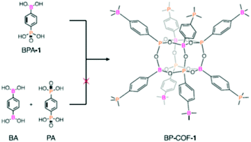 | ||
| Fig. 16 Synthesis of BP-COF-1. Reproduced and adapted with permission from ref. 57, Copyright The American Association for the Advancement of Science (2020). | ||
4.3 Mechanistic studies for the synthesis of COFs
In the aforementioned sections, it can be seen that there is a large number of linkages from which highly crystalline COFs are obtained when the monomers are employed under suitable reaction methods and conditions. However, very few reports elaborate on the mechanistic pathways to describe how these monomers combine to give long-range orders and what factors affect the crystalline growth. In this section, we emphasize the mechanistic details of two widely explored linkages, i.e., boronic ester and imine, formed with different synthetic methods under different conditions.The next year, another study was published by the same group focusing on the rate of framework growth and nucleation and factors inducing moisture stability in the product.173 It has been elucidated that the rate-determining step in the boronic ester-linked COF formation reactions is not the formation of the C2O2B ring, namely, the 2D intermolecular stacking path occurs when growth of already existing micro-crystallite COFs predominates. Furthermore, factors such as controlled temperature (60–90 °C), aromaticity of monomers (pyrene vs benzene-core), amount of competitor (TCAT) used in the beginning or during the reaction, and quantity of liquid additives (MeOH and H2O) are the deciding factors influencing the crystallinity and stability of the COF.
The effect of modulator on the microwave-assisted synthesis of COF-5 was closely studied by Bein and co-workers in 2016 using the functionalized truncated boronic acids, MPBA and CPBA.174 The reaction mixture was sealed in a microwave tube and heated to 100 °C at 300 W power. The report showed that with 10% modulation (HHTP![[thin space (1/6-em)]](https://www.rsc.org/images/entities/char_2009.gif) :
:![[thin space (1/6-em)]](https://www.rsc.org/images/entities/char_2009.gif) BDBA
BDBA![[thin space (1/6-em)]](https://www.rsc.org/images/entities/char_2009.gif) :
:![[thin space (1/6-em)]](https://www.rsc.org/images/entities/char_2009.gif) modulator = 2
modulator = 2![[thin space (1/6-em)]](https://www.rsc.org/images/entities/char_2009.gif) :
:![[thin space (1/6-em)]](https://www.rsc.org/images/entities/char_2009.gif) 2.70
2.70![[thin space (1/6-em)]](https://www.rsc.org/images/entities/char_2009.gif) :
:![[thin space (1/6-em)]](https://www.rsc.org/images/entities/char_2009.gif) 0.6), the reaction time increased by 30 min, forming a large number of crystallite domains with sizes of 60 and 56 nm for MPBA and CPBA, respectively. Moreover, the highest XRD intensity and BET surface area were obtained under these conditions, i.e., 2100 m2 g−1, which is ∼35% greater than that of the unmodulated COF-5. Further studies done by Dichtel's group revealed that the use of nitrile-containing co-solvents help in stabilizing the colloidal suspension for over a month.175 This promotes the growth of 2D COFs by inhibiting the particle aggregation, ameliorating the quality of its single crystals. Later, in a follow-up paper published in 2018 by the same group, it was proven that control of the crystallite size was achieved via the rate of monomer addition after stabilizing the COF colloidal suspension.176 The SAXS/WAXS studies showed that with the slow addition of the monomer (0.1 equiv. h−1), the crystallinity of the framework increased, suppressing the nucleation process, which contradicts the results of fast monomer addition (1.0 equiv. h−1). These studies provide a way to overcome the crystallite growth and nucleation issues for knitting boronic ester-linked COFs.
0.6), the reaction time increased by 30 min, forming a large number of crystallite domains with sizes of 60 and 56 nm for MPBA and CPBA, respectively. Moreover, the highest XRD intensity and BET surface area were obtained under these conditions, i.e., 2100 m2 g−1, which is ∼35% greater than that of the unmodulated COF-5. Further studies done by Dichtel's group revealed that the use of nitrile-containing co-solvents help in stabilizing the colloidal suspension for over a month.175 This promotes the growth of 2D COFs by inhibiting the particle aggregation, ameliorating the quality of its single crystals. Later, in a follow-up paper published in 2018 by the same group, it was proven that control of the crystallite size was achieved via the rate of monomer addition after stabilizing the COF colloidal suspension.176 The SAXS/WAXS studies showed that with the slow addition of the monomer (0.1 equiv. h−1), the crystallinity of the framework increased, suppressing the nucleation process, which contradicts the results of fast monomer addition (1.0 equiv. h−1). These studies provide a way to overcome the crystallite growth and nucleation issues for knitting boronic ester-linked COFs.
Based on the summary of the above-discussed information, a comprehensive mechanism for the formation of a COF with boronic ester linkages under either high temperature or microwave-assisted conditions is thoroughly displayed in Fig. 17A.
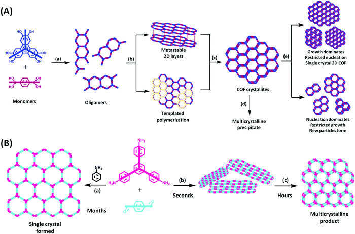 | ||
| Fig. 17 Mechanism for the formation of (A) 2D boronic ester-linked and (B) imine-linked COFs proposed by analyzing the information from the detailed mechanistic studies. Adapted from ref. 5, 173–177, 180 and 182. | ||
During the formation of COF-5 from HHTP and PDBA, the monomers initially combine to give oligomers in step a, which then stack reversibly in step b. During this stage, an addition of diol or boronic acid-mimicking modulators controls the growth by slackening the reaction. On proceeding further, either the oligomeric sheets stack together forming metastable layers, or one sheet acts a base for template polymerization. Consequently, each stage gives COF crystallites through step c, which require further treatments to get the desired product. Control of the various aforementioned factors in the early stages helps to build the crystallites at this stage. By recovering these crystallites, a multi-crystalline precipitate is obtained via step d, whereas treating them with suitable stabilizing agents yields single crystals by preventing nucleation (step e). This can occur when the monomers are slowly added at this point. On the contrary, the fast addition of the monomer yields new crystallite particles via nucleation, and thus single crystal growth is prevented.
![[thin space (1/6-em)]](https://www.rsc.org/images/entities/char_2009.gif) :
:![[thin space (1/6-em)]](https://www.rsc.org/images/entities/char_2009.gif) 1 v/v) was heated to 70 °C for 5 days. The glacial acetic acid catalyst and H2O content were maintained for the minimum quantity to be ≥1 M and 3.3 M, respectively, which was required to initiate crystallinity within the framework and attain higher yields. Additionally, the BET surface area of the initial amorphous solid was found to be 18 m2 g−1, which further increased to 287 m2 g−1 over a period of two days. This supports the observation that the amorphous-to-crystalline imine COF transformation is a two-step process, i.e., fast polymerization of soluble monomers to an amorphous organic polymer at elevated temperature followed by the imine exchange process, which increases the tendency of error-correction.
1 v/v) was heated to 70 °C for 5 days. The glacial acetic acid catalyst and H2O content were maintained for the minimum quantity to be ≥1 M and 3.3 M, respectively, which was required to initiate crystallinity within the framework and attain higher yields. Additionally, the BET surface area of the initial amorphous solid was found to be 18 m2 g−1, which further increased to 287 m2 g−1 over a period of two days. This supports the observation that the amorphous-to-crystalline imine COF transformation is a two-step process, i.e., fast polymerization of soluble monomers to an amorphous organic polymer at elevated temperature followed by the imine exchange process, which increases the tendency of error-correction.
A big step was taken by Yaghi and co-workers by judiciously adding a suitable amine-based modulator to obtain 3D imine-linked COFs. The widely used modulator is aniline, which is a monofunctional mimic of the diamine monomer and competes in the COF formation reaction. Consequently, large-size crystals of good quality grow by inhibiting nucleation. By following the aniline modulation process, large single crystals (size in parentheses) of COF-300 (∼60 μm), COF-303 (∼15 μm), LZU-79 (∼100 μm) and LZU-111 (∼50 μm) were obtained.6 In all cases, good-quality crystals were obtained under solvothermal conditions when the aniline modulator concentration varied from 15–80 equiv. The other amine and aldehyde-based modulators used for knitting prolonged 2D and 3D COF nets include propylamine, 2-aminopyridine, benzaldehyde, and 2,4,6-trimethylbenzaldehyde.178–180
A few months ago, the mechanochemical synthetic approach for the synthesis of imine-linked COFs was deeply studied to understand its mechanistic pathway. Four different COFs, viz., COF-LZU1, TbBd-COF, IISERP-COF4 and N-COF, were constructed by liquid-assisted mechanochemical milling of their respective monomers in an X-ray transparent PMMA milling jar. It was evidently shown that by controlling the ratio of liquid additive (dioxane with respect to the reactants) and providing a catalyst suitable for Schiff base formation, very high crystallinity of the framework could be achieved by this method. With this approach, the limited surface area is also enhanced to a good extent when Sc(OTf)3 was utilized for catalyzing the reaction.181 The drawbacks of the COF activation process were also reported last year, where the collapse of imine-linked frameworks was reported during high-vacuum activation. The solution to this problem was provided by activating the fragile frameworks with N2 or supercritical CO2 flow activation using an ultrahigh-pressure reactor.182
Fig. 17B shows the summarized mechanism, which presents insight into obtaining single crystals of 2D imine-linked COFs via the use of an aniline modulator in large excess (step a), giving the desired product in 30–80 days. However, a polycrystalline material can be obtained in a few hours by using amorphous COF sheets as a precursor (step c), which can be produced within seconds from the monomers (step b).
5. Structural characterization
5.1 Fourier-transform infrared (FTIR) spectroscopy
This technique is a very basic and widely used technique to detect the functional groups present in any organic system. Almost all organic polymers, particularly COFs, have been characterized using this method due to its easy accessibility and user-friendly approach. This technique can be easily operated and analyzed to obtain subtle results about the functional groups present in materials. It is mostly used to help determine the completion of reactions for covalent organic frameworks, i.e., in the case of Schiff-base imine condensation, the disappearance of the peaks corresponding to an amine and an aldehyde near 3500–3300 and 1690 cm−1, respectively, indicates that the reaction is complete. An example for this is COFDAAQ-BTA-3DG, which was synthesized via the combination of a ditopic amine unit and a tritopic aldehyde unit.183 The fully formed product was witnessed by the appearance of a new C–N stretching peak (∼1331 cm−1) and the absence of the strong carbonyl stretching frequency near 1695 cm−1 (Fig. 18). This framework was well characterized using other techniques for the confirmation of its synthesis (vide infra).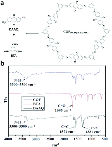 | ||
| Fig. 18 (a) Structures of DAAQ and BTA monomers and COFDAAQ-BTA-3DG and (b) their characterization using FT-IR spectroscopy. Reproduced with permission from ref. 183, Copyright the American Chemical Society (2015). | ||
Moreover, as mentioned in Section 4.2, triazine-linked COFs can also be monitored using the FTIR technique by noting the disappearance of the C–N stretching frequency for nitriles and appearance of a peak corresponding to imines. The formation of CTF-1 was studied at different reaction times and various reaction temperatures. The intense carbonitrile peak at 2218 cm−1 disappeared, which clearly indicated the successful occurrence of the trimerization reaction. This was further supported by the emergence of a strong absorption peak at 1352 cm−1, corresponding to the formation of a triazine ring.20
The boron-containing frameworks have also been well characterized using FTIR spectroscopy. COF-1 and COF-5 (Fig. 19a and c) are linked by boroxine- and boronic ester-linkages, respectively. The FTIR peak at 711 cm−1 increased with respect to the (B3O3) boroxine ring (Fig. 19b), whereas the peak at 1026 cm−1 corresponds to the boronic ester ring B-C stretching frequency (Fig. 19d).4 Moreover, the B–O stretching frequencies in both cases can be seen at 1378 and 1342 cm−1 for COF-1 and at 1347 and 1332 cm−1 for COF-5.
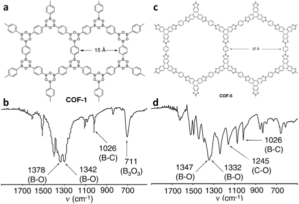 | ||
| Fig. 19 Condensation reactions of boronic acids used to produce extended COF structures of (a) COF-1 and (c) COF-5. FTIR spectra highlighting the characteristic boron functional group bands of (b) COF-1 and (d) COF-5. Reproduced with permission from ref. 4, Copyright The American Association for the Advancement of Science (2005). Asterisks indicate spinning side-band peaks. | ||
Similarly, the synthesis of borazine-linked COFs was monitored by the appearance of the B–N stretching frequency near 1500 cm−1 and strong attenuation of the N–H and B–H frequencies, as shown for BLP-2(H) in Fig. 20.60
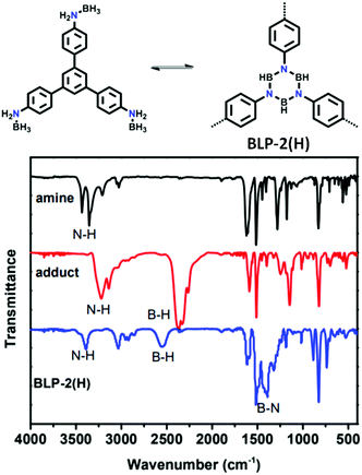 | ||
| Fig. 20 Structure of BLP-2(H) together with its monomer and its characterization using FT-IR spectroscopy. Reproduced with permission from ref. 60, Copyright The Royal Society of Chemistry (2012). | ||
Considering that COFs are known to form numerous linkages, the formation of these linkages through various reversible reactions has been monitored using FTIR analysis. One of these distinctive linkages is the azidoxy-linked framework, where the nitroso-functionalized monomers dimerize to form a trans-adioxy bond. The POR-COF was constructed using a protected tetrakis(aryl hydroxylamine)porphyrin unit via room temperature synthesis (see Section 4.2).35 According to the FT-IR spectrum, it was observed that with the propagation of dimer formation, the peaks at 1735 cm−1 for the C![[double bond, length as m-dash]](https://www.rsc.org/images/entities/char_e001.gif) O stretching and 2950–2850 cm−1 for the C–H stretching disappeared (Fig. 21a and b). Moreover, a new peak at around 1283 cm−1 for N
O stretching and 2950–2850 cm−1 for the C–H stretching disappeared (Fig. 21a and b). Moreover, a new peak at around 1283 cm−1 for N![[double bond, length as m-dash]](https://www.rsc.org/images/entities/char_e001.gif) N stretching was seen, representing completion of the reaction.
N stretching was seen, representing completion of the reaction.
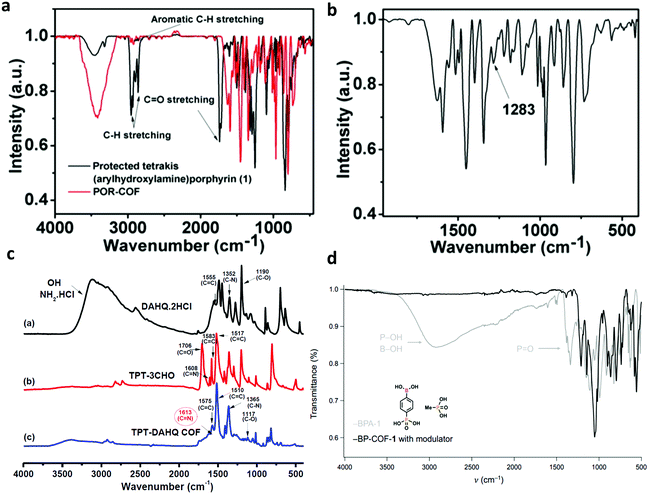 | ||
| Fig. 21 FT-IR spectra of (a) azidoxy-linked POR-COF and its monomer with its magnified spectrum (b), (c) TAPT-DAHQ COF and its monomers DAHQ·2HCl and TAPT-3CHO and (d) BP-COF-1 and its monomer BPA-1. Reproduced with permission from: (a and b) ref. 35, Copyright The Royal Society of Chemistry (2016); (c) ref. 164, Copyright John Wiley and Sons (2019) and (d) ref. 57, Copyright The American Association for the Advancement of Science (2020). | ||
Likewise, the formation of benz-bis(oxazole) was monitored, where the FTIR spectra of the monomers and the product were simultaneously plotted and compared. In Fig. 21c, it can be seen that the peaks corresponding to C![[double bond, length as m-dash]](https://www.rsc.org/images/entities/char_e001.gif) N (1608 cm−1), C
N (1608 cm−1), C![[double bond, length as m-dash]](https://www.rsc.org/images/entities/char_e001.gif) C (1583–1517 cm−1) and C–O (1706 cm−1) for the TPT-3CHO monomer and that for C–N bending (1352 cm−1), C
C (1583–1517 cm−1) and C–O (1706 cm−1) for the TPT-3CHO monomer and that for C–N bending (1352 cm−1), C![[double bond, length as m-dash]](https://www.rsc.org/images/entities/char_e001.gif) C (1555 cm−1), C–O (1190 cm−1) and phenolic –OH and NH3Cl (∼3200 cm−1) for the DAHQ·2HCl monomer disappeared during the reaction, whereas peaks for C
C (1555 cm−1), C–O (1190 cm−1) and phenolic –OH and NH3Cl (∼3200 cm−1) for the DAHQ·2HCl monomer disappeared during the reaction, whereas peaks for C![[double bond, length as m-dash]](https://www.rsc.org/images/entities/char_e001.gif) N (1613 cm−1) and C–O (117 cm−1) appear. This is attributed to the formation of a benzobisoxazole ring.164
N (1613 cm−1) and C–O (117 cm−1) appear. This is attributed to the formation of a benzobisoxazole ring.164
The synthesis of the highly connected BP-COF-1 using BP-1 was also studied using FTIR spectroscopy (Fig. 21d). The broad peak corresponding to free –OH groups and sharp P![[double bond, length as m-dash]](https://www.rsc.org/images/entities/char_e001.gif) O stretching in the monomer unit were attenuated completely after completion of the reaction.57
O stretching in the monomer unit were attenuated completely after completion of the reaction.57
Monitoring the formation of the β-ketoenamine linkage using FT-IR was reported in 2015, which compared the fabrication of the TpBDH COF from 1,3,5-triformylphloroglucinol (Tp) and pyromellitic-N,N′-bisaminoimide (BDH) units (Fig. 22).149 The appearance of peaks at 1583 and 1273 cm−1 correspond to the C![[double bond, length as m-dash]](https://www.rsc.org/images/entities/char_e001.gif) C and C–N stretching, respectively, which match that of the reference compound. Conversely, the monomer peaks for N–H and C
C and C–N stretching, respectively, which match that of the reference compound. Conversely, the monomer peaks for N–H and C![[double bond, length as m-dash]](https://www.rsc.org/images/entities/char_e001.gif) O stretching are fully attenuated in the product.
O stretching are fully attenuated in the product.
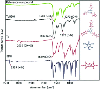 | ||
| Fig. 22 FT-IR spectra of TpBDH COF with its monomers, Tp and BDH, and the reference compounds. Reproduced and adapted with permission from ref. 149, Copyright The Royal Society of Chemistry (2015). | ||
![[double bond, length as m-dash]](https://www.rsc.org/images/entities/char_e001.gif) C and C–N peaks at 1590 and 1270 cm−1 for the bulk COF confirmed the reaction progress. Afterwards, the exfoliated DaTp-CON showed some additional stretching frequency bands at 2937, 2857 and 1695 cm−1, corresponding to the C–H and C
C and C–N peaks at 1590 and 1270 cm−1 for the bulk COF confirmed the reaction progress. Afterwards, the exfoliated DaTp-CON showed some additional stretching frequency bands at 2937, 2857 and 1695 cm−1, corresponding to the C–H and C![[double bond, length as m-dash]](https://www.rsc.org/images/entities/char_e001.gif) O groups from the alkyl chain and imide unit of N-hexylmaleimide (Fig. 23b).
O groups from the alkyl chain and imide unit of N-hexylmaleimide (Fig. 23b).
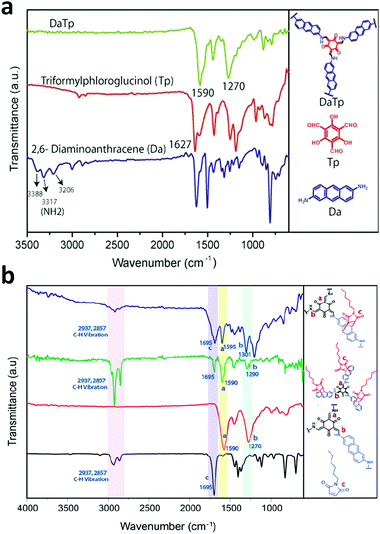 | ||
| Fig. 23 FT-IR spectra of (a) DaTp COF and its monomers, Tp and Da and (b) DaTp-CON with N-hexylmaleimide. Reproduced with permission from ref. 110, Copyright John Wiley and Sons (2016). | ||
![[double bond, length as m-dash]](https://www.rsc.org/images/entities/char_e001.gif) O) group and disappearance of the C
O) group and disappearance of the C![[double bond, length as m-dash]](https://www.rsc.org/images/entities/char_e001.gif) N imine stretching peaks at ∼1622 cm−1 (for 1′ and 2′) support the linker transformation process (Fig. 24).
N imine stretching peaks at ∼1622 cm−1 (for 1′ and 2′) support the linker transformation process (Fig. 24).
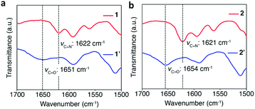 | ||
| Fig. 24 FT-IR spectra of imine-linked (a) TPB-TP COF (1) and (b) 4PE-1P-COF (2) in red with their oxidized products amide-linked (a) TPB-TP COF (1′) and (b) 4PE-1P-COF (2′) in blue. Reproduced with permission from ref. 184, Copyright the American Chemical Society (2016). | ||
A similar study was done to strengthen the imine linked TTI-COF by post-synthetic modification to form the thiazole-linked TTT-COF at high thermal conditions (vide Section 4.2).170 The disappearance of the peak at 1627 cm−1 corresponds to the C![[double bond, length as m-dash]](https://www.rsc.org/images/entities/char_e001.gif) N imine stretching in TTI-COF and the emergence of a new C
N imine stretching in TTI-COF and the emergence of a new C![[double bond, length as m-dash]](https://www.rsc.org/images/entities/char_e001.gif) N stretching for the thiazole ring can be seen at 1609 cm−1.
N stretching for the thiazole ring can be seen at 1609 cm−1.
As exemplified above, this is the foremost and a very basic tool that can be used in different aspects for functional group analysis in a framework.
5.2 Solid-state magic angle spinning (ss-MAS) nuclear magnetic resonance (NMR) spectroscopy
Covalently-bonded organic polymers are usually insoluble in common solvents, which make their analysis difficult using the NMR technique given that it requires high solubility of the sample in deuterated solvents. Therefore, magic-angle spinning of the solid-state sample is done at an angle 54.74° with respect to the magnetic field during NMR analysis. This technique is used for monitoring the formation of COFs by comparing the NMR peaks of the polymer with their respective monomers. The first set of COFs was comprised of B, C, O and N-atoms, where 11B, 13C and 15N NMR spectroscopy were utilized to corroborate the framework structure. Recently, 31P and 29Si NMR spectroscopy were exploited for their characterization with the incorporation of P and Si atoms in the linkages. ss-MAS NMR was first implemented for COF-1 and COF-5 to study the completion of their reaction. The 11B-MAS NMR spectra for both COFs do not match that of the monomer benzenediboronic acid (BDBA) and totally matches with their model compounds. This indicates the formation of the boroxine ring in COF-1 and boronic ester in COF-5 (Fig. 25a and b), respectively.4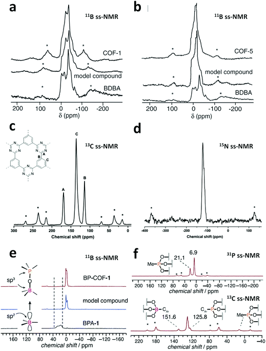 | ||
| Fig. 25 11B magic-angle spinning NMR spectra of (top) COF, (middle) model compound and (bottom) BDBA for (a) COF-1 and (b) COF-5. Reproduced and adapted. 13C CP-MAS solid-state NMR (c) and 15N CP-MAS solid-state NMR (d) of CTF-0. (e) Overlay of the 11B solid-state (ss) NMR spectra of BP-COF-1, a molecular boro-phosphonate model compound and BPA-1. (f) 31P and 13C NMR spectra of BP-COF-1. Me, methyl. Asterisks denote spinning sidebands. Reproduced with permission from: (a and b) ref. 4, Copyright The American Association for the Advancement of Science (2005); (c and d) ref. 19, Copyright the American Chemical Society (2013) and (e and f) ref. 57, Copyright The American Association for the Advancement of Science (2020). | ||
13C and 15N CP-MAS NMR spectra were used to detect the formation of the triazine ring in a covalent triazine framework, viz. CTF-0. 13C NMR indicated three major peaks at δ = 167, 136 and 114 ppm, which correspond to the three sp2 carbons (the deshielded peak for the triazine ring and other two for the phenyl ring) and no peak was observed at δ = 110 ppm, ruling out the possibility of any residual CN group from the monomer unit (Fig. 25c and d).19 In addition, the 15N ssNMR spectrum helped to identify the triazine moiety, with a peak observed at −121 ppm for the triazine-ring N-atom.
Similarly, 11B-MAS NMR spectroscopy was used to validate the complete utilization of monomers in the polycubane-based BP-COF-1 (Fig. 25e).57 The single doublet of the framework near 0 ppm for the COF is consistent with the model compound, whereas this peak was not observed for sp2-hybridised boron in the monomer BPA-1. Moreover, 31P and 13C ssNMR spectroscopy were also used to confirm the reaction (Fig. 25f). The 31P NMR spectrum of BP-COF-1 showed two peaks at 6.9 and 21.1 ppm, indicating the presence of two distinct phosphorous atoms in the framework. The less intense peak at 21.1 ppm represents the methylphosphates present at the crystallite edges, whereas the more shielded NMR signal at 6.9 ppm represents the CAr–P unit. Conversely, the 13C CP-MAS NMR spectrum displays peaks in the aromatic region between 151.6 and 125.8 ppm, which correspond to the aromatic carbon bonded to the boron and phosphorus atoms, respectively.
Silicon-containing frameworks have been synthesized to incorporate ionic nature in COFs (see Section 4.2). Therefore, for their characterization, 29Si CP-MAS ssNMR spectroscopy has been exploited. The synthesis of an anionic SiCOF was validated using 29Si NMR spectroscopy, which showed a single peak at −143 ppm, corresponding to the hexacoordinated Si-atom in the framework.165 However, no peak for the TMOS monomer at −79 ppm was seen. Considering that the COF was anionic and stabilized by Li+ and Na+ ions, the rarely utilized 7Li and 23Na-MAS NMR spectra were recorded, showing peaks at −1 ppm for SiCOF-Li and −24 ppm for SiCOF–Na, respectively. This is a unique example of the use of Na and Li NMR spectroscopy.
5.3 X-ray diffraction (XRD)
As mentioned above, COFs are synthesized in the form of small crystallites/powders, highly ordered thin films and small single crystals. Therefore, X-ray diffraction is an extensively exploited analytical technique used to elucidate the crystallographic structure of these materials. The powders and films are characterized using PXRD (small/wide angle X-ray diffraction) supported by theoretically simulated peaks, whereas single crystals with good mosaic structures are characterized using the SCXRD technique.Structure determination. The first highly crystalline COFs were the boron-containing COF-1 and COF-5, which were characterized by PXRD, giving sharp peaks corresponding to different (h k l) planes, as shown in Fig. 26a and b, respectiverly.4 To confirm these planes, the extended structures of both frameworks were modelled and their simulated powder patterns were calculated. The simulated patterns were found to be well fitted with the experimental patterns, indicating the formation of staggered AB stacked and eclipsed AA stacked frameworks for COF-1 and COF-5 with the hexagonal lattice space groups of P63/mmc and P6/mmm, respectively. The honeycomb framework sets in the gra and bnn network with and interlayer spacing of 3.328 and 3.460 Å for COF-1 and COF-5, respectively.
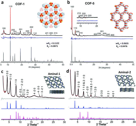 | ||
| Fig. 26 X-ray analysis of (a) COF-1 and (b) COF-5 with the observed pattern in black, the refined profile in red, and the difference plot in blue (observed minus refined profiles). The bottom trace is the calculated PXRD pattern from Cerius.2 Experimental (black) and refined (red) PXRD patterns of (c) aminal-COF-1 and (d) aminal-COF-2. Difference plot between the experimental and refined PXRD patterns (grey) and simulated PXRD patterns for eclipsed (blue) and staggered (pink) structures. Inset is the perspective and top views of the structural representation of both COFs in eclipsed stacking. Reproduced with permission from: (a and b) ref. 4, Copyright The American Association for the Advancement of Science (2005) and (c and d) ref. 38, Copyright the American Chemical Society (2019). | ||
Aminal-linked COFs, viz. aminal-1 and aminal-2, diffract to give very sharp and intense peaks, corresponding to the (100), (010) and (110) facets, which match well with the simulated patterns with fairly low fitting parameters (Fig. 26c and d), respectively.38 Both frameworks show eclipsed (AA) stacking in the triclinic P1 space group with the rarely fabricated 2D cpi topology (vide supra, Section 2.1). It was observed that the two COFs possess piperazine units, which exist in the chair-form, resulting in an increase in the interlayer distance (beyond 6 Å) and reduction in aromatic π–π interactions.
Similarly, a nitrogen-rich azine-linked COF with triazine cores, namely ANCOF, showed very sharp and intense diffraction peaks in small/wide angle PXRD, which are consistent with the simulated pattern calculated using the Pawley and Rietveld refinement methods with good profile-fitting values.154 The framework was set in the triclinic P![[1 with combining macron]](https://www.rsc.org/images/entities/char_0031_0304.gif) space group with an AB-type interpenetrated arrangement, as shown in Fig. 27. The interlayer separation was calculated to be 4.5 Å.
space group with an AB-type interpenetrated arrangement, as shown in Fig. 27. The interlayer separation was calculated to be 4.5 Å.
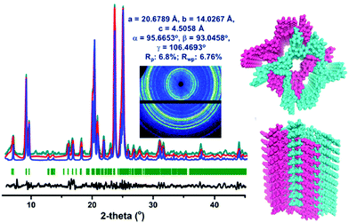 | ||
| Fig. 27 Structural analysis of ANCOF: (left) experimental PXRD pattern (blue), simulated PXRD pattern (cyan), and its fit by Pawley refinement (red) with a minimum difference (black line). (right) Structures of ANCOF obtained from the Rietveld refinement; AB stacking is shown in cyan and pink color. Reproduced with permission from ref. 154, Copyright the American Chemical Society (2020). | ||
The two imine-linked COFs, 2,3-DhaTta and 2,3-DhaTab, were found to have the AA stacked pattern (Fig. 28b and c), respectively.79 As mentioned in Section 3.2.1, the strong π–π interactions of 2,3-DhaTta COF due to its planar building units were clearly depicted from its high intensity (100)/(001) peak ratio of 46.21 in comparison to that of the 2,3-DhaTab COF, which is 5.01 (Fig. 28a and d), respectively. The simulated results showed the greater π–π stacking energy of −1634.2 kJ mol−1 for the former COF in comparison to that of the latter of −1578.6 kJ mol−1. The deviation from planarity of the phenyl-core 2,3-DhaTab COF possibly indicates the improper growth of the material along the c-axis, which disrupts the proper stacking and yields bent crystallites with a lower BET surface area.
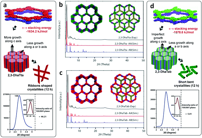 | ||
| Fig. 28 Mechanism for the formation of ribbon (a) and hollow sphere (d) for CPP 2,3-DhaTta, and 2,3-DhaTab, respectively. PXRD patterns of as-synthesized (b) 2,3-DhaTta and (c) 2,3-DhaTab (black) compared with the eclipsed (red) and staggered (blue); eclipsed (left) and staggered (right) stacking models shown in the inset. Reproduced and adapted with permission from ref. 79, Copyright John Wiley and Sons (2016). | ||
Optimization of synthetic conditions. It was discussed in the previous sections (particularly, Section 4) that optimization of the reaction conditions for the synthesis of COFs with prolonged periodicity, in-built thermal, chemical and water stability and functionalization is a very tedious task. A large number of factors must be thoroughly considered during their synthesis, which makes the process laborious and time-consuming. However, the utilization of appropriate characterization techniques to monitor the reaction progress under different conditions must be considered to save time and gain a better understanding. This case was observed when the TFPC-NDA COF was synthesized under two different reaction conditions (Fig. 29a).24 The use of an acid catalyst to activate the aldehydic functional group under solvothermal conditions has been done for long time, but in this rarely seen case, the COF was synthesized without the use of the AcOH catalyst. The PXRD pattern showed intense peaks when the acid was not used as a catalyst during the solvothermal synthesis, whereas very broad peaks were observed when the synthesis was conducted with acid, indicating the amorphous nature of the COF. Furthermore, the COF was utilized for VOC and TNP sensing (see Section 6.2) and its stability in each application was validated using the PXRD technique, as discussed further below.
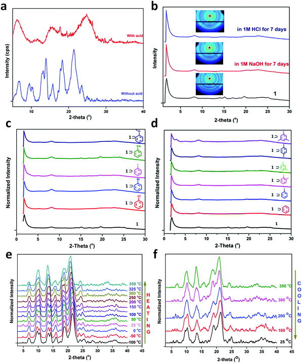 | ||
| Fig. 29 (a) PXRD patterns of TFPC-NDACOF prepared without an acid and its analogue prepared in the presence of an acid. (b) WAX patterns of TFPC-NDACOF before and after immersion in 1 M NaOH and 1 M HCl for 7 days (inset: 2D WAX images). (c and d) WAX patterns showing that the crystallinity of TFPC-NDACOF was maintained after the absorption of different electron-withdrawing and electron-donating aromatic VOCs, respectively. Variable-temperature powder diffraction patterns of TFPC-NDA COF upon (e) heating from −100 °C to 350 °C and (f) cooling to 25 °C. Reproduced with permission from ref. 24, Copyright The Royal Society of Chemistry (2018). | ||
Additionally, a few in situ PXRD experiments have been performed to understand the formation of the framework. This ‘in situ’ approach is beneficial to check the reaction requirements to obtain a particular framework from amorphous organic polymers. For instance, during the study of the mechanochemical synthesis of four COFs, i.e., COF-LZU1, TbBd-COF, IISERP-COF4 and N-COF (vide supra, Section 4.3), the in situ time-resolved synchrotron PXRD studies revealed the appearance of the first peak corresponding to the 100 plane in 3, 10, 10 and 4 min, respectively.181 Moreover, during the course of the reaction, the peaks intensified and reached the highest value after a certain time. At this time, the peak intensity matched that from the ex situ PXRD measurements. Additionally, the ex situ PXRD data of the COF-LZU1 intermediate, which crystallizes in the triclinic P![[1 with combining macron]](https://www.rsc.org/images/entities/char_0031_0304.gif) space group, revealed that there is one triple imine unit and one-half dioxane molecule in the asymmetric unit.
space group, revealed that there is one triple imine unit and one-half dioxane molecule in the asymmetric unit.
Stability confirmation. For their use in various applications, COFs must be stable in different conditions. Particularly, in the case of sensing, their stability in the presence of different analytes is necessary to avoid collapse of the framework. A large number of systems can act as analytes, such as nitro-rich explosives, metal ions and anions, acids, bases, small molecules such as ammonia, and various organic solvents. Besides, the stability of the framework at different temperatures can also be investigated using the variable-temperature PXRD (VT-PXRD) technique.
Several examples of this have been reported in the literature, two of which are the β-ketoenamine-linked TpPa-1 and TpPa-2 COFs. Their exceptionally high thermal, water and chemical stability were confirmed by the PXRD technique, as shown in Fig. 30.67 Other analytic methods such as FESEM, BET and TGA analysis help in getting more detailed information regarding the retention of morphology, high surface areas before and after treatment with different environments and the decomposition temperature, respectively (vide infra).
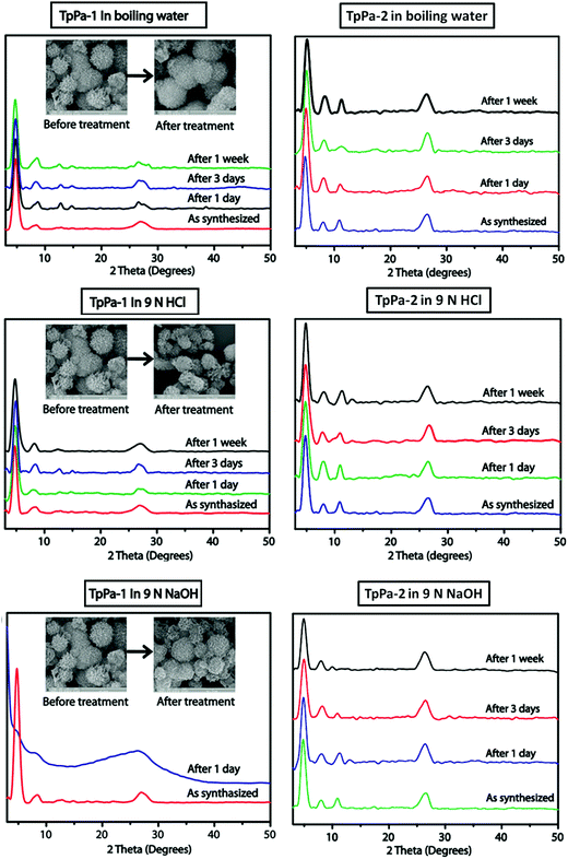 | ||
| Fig. 30 PXRD patterns of TpPa-1 (left) and TpPa-2 (right) in boiling water, 9 N HCl and 9 N NaOH, showing their stability. Reproduced with permission from ref. 67, Copyright the American Chemical Society (2012). | ||
Another example, continuing from the previous subsection, is TFPC-NDA COF, which is a semi-flexible COF synthesized from 1,3,5-tri(4-formylphenoxy)cyanurate (TFPC) and naphthalene diamine (NDA). The COF was highly stable in various acid/basic conditions (1 M HCl and 1 M NaOH solutions for 7 days) based on its wide angle PXRD patterns (Fig. 29b).24 The 2D WAX image showed the first diffraction peak from the WAX pattern. This highly stable COF was exploited for sensing different analytes, in which its stability was checked. The intact WAX patterns of the COF in different electron-poor and electron-rich (Fig. 29c and d) aromatic analytes confirmed its chemical stability, respectively. In addition, the thermal stability of the COF in a broad temperature range of 350 °C to −100 °C was also verified using VTPXRD (Fig. 29e), where ramping up or down the temperature from both extremes did not disrupt its framework integrity (Fig. 29f).
In 2013, the first examples of single-crystalline azidoxy-linked frameworks were reported, viz. NPN-1, NPN-2 and NPN-3, by Beaudoin et al. The crystals were grown in different solvents, yielding a good mosaic with a size of ∼10 mm.88 Both NPN-1 and NPN-2 crystallized in the tetragonal space group P![[4 with combining macron]](https://www.rsc.org/images/entities/char_0034_0304.gif) b2, knitting four-fold-interpenetration along c-axis, whereas NPN-3 crystallized in the P42/n with six-fold-entanglement. All three frameworks exhibited the dia topology, in which the two Td-nodes are at a distance of 12.26, 12.76 and 15.39 Å from each other for the methane, silane and adamantane-core tetranitroso unit. This is ascribed to the long C-Si bond in NPN-2 compared to the C–C bond in NPN-1. Moreover, the adamantane-core is bigger, and thus the framework could afford six-fold interpenetration.
b2, knitting four-fold-interpenetration along c-axis, whereas NPN-3 crystallized in the P42/n with six-fold-entanglement. All three frameworks exhibited the dia topology, in which the two Td-nodes are at a distance of 12.26, 12.76 and 15.39 Å from each other for the methane, silane and adamantane-core tetranitroso unit. This is ascribed to the long C-Si bond in NPN-2 compared to the C–C bond in NPN-1. Moreover, the adamantane-core is bigger, and thus the framework could afford six-fold interpenetration.
As mentioned earlier, the first imine-linked COF, COF-300, was analyzed by the PXRD technique and its simulated pattern to obtain its structural information in 2009. It was determined that the framework was crystallized in the tetragonal I41/a space group with the dia-c5, topology which does not obey the formula for the degree of interpenetration, i.e., N = 2a/c, where ‘a’ and ‘c’ are the cell parameters for the tetragonal lattice. Recently, it was found from the SCXRD data of the 3D COF-300 that the framework is seven-fold interpenetrated (dia-c7) with unit cell parameters of a = b = 28.280 Å and c = 10.079 Å, which is in accordance with the formula (Fig. 31).6 The possible explanation for this is the aging effect, which increased the degree of interpenetration during its synthesis (vide supra, Section 3.2.2).
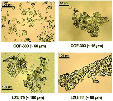 | ||
| Fig. 31 Optical microscopy images of single-crystalline COFs obtained in the presence of aniline. Reproduced with permission from ref. 6, Copyright The American Association for the Advancement of Science (2018). | ||
Besides COF-300, single crystals of the imine-linked 3D COF-303, LZU-79 and LZU-111 were also obtained and diffracted. It must be noted that the symmetry, topological view and degree of interpenetration in COF-300 and COF-303 are identical with a slight difference in imine connectivity, which could not be detectable using the PXRD technique. Therefore, the use of the SCXRD method is essential here.
The COF LZU-79 was reticulated from COF-300, in which the terephthaldehyde unit was replaced by the longer 4,7-bis(4-formylbenzyl)-1H-benzimidazole (BFBZ). LZU-79 crystallizes in the P42/n space group with a high degree of entanglement (dia-c10). Moreover, large-sized crystals of a new chiral imine-linked LZU-111 COF with a size of ∼60 μm were grown using aniline as the modulator. This chiral COF crystallizes in the P65 space group and exhibits a different topology, i.e., lon-b-c3 (vide supra, Section 2.1)
For a single crystal to be successfully diffracted, the required size is ∼0.5 mm or larger. However, due to very little success in obtaining appropriately sized single-crystal COFs, the XRD technique has not been efficiently utilized in this area. Accordingly, the rotation electron diffraction method is employed when the single crystal size varies from nano- to micrometers. The RED technique is further discussed in Section 5.4.2.
5.4 Microscopic techniques
A very important and widely used characterization technique for the analysis of COFs is electron microscopy, which uses a negatively charged electron beam in place of a light source. This technique gives detailed information about the properties of materials such as surface morphology, phase and bulk purity, reproducibility, and elemental mapping.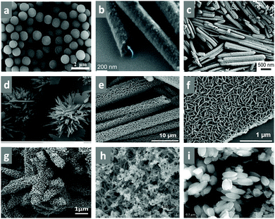 | ||
| Fig. 32 FESEM images showing different surface morphologies of COFs. Reproduced with permission from: (a) ref. 186, Copyright the American Chemical Society (2019); (b) ref. 187, Copyright John Wiley and Sons (2018); (c) ref. 141, Copyright the American Chemical Society (2019); (d) ref. 68, Copyright the American Chemical Society (2019); (e and f) ref. 188, Copyright Elsevier (2019). (g) ref. 138, Copyright The Royal Society of Chemistry (2021); (h) ref. 189, Copyright the American Chemical Society (2017) and (i) ref. 57, Copyright The American Association for the Advancement of Science (2020). | ||
The homogeneity of the bulk sample and reaction completion can be confirmed using the FESEM technique, as shown in Fig. 32i.57 The first synthesized boroxine and boronic ester-linked COFs, COF-1 and COF-5, showed an aggregated platelet-like morphology (Fig. 33).4 The framework can have different particle sizes, varying from a few microns (μm) to nanometers (nm). Highly magnified electron images can be obtained using the TEM technique, as discussed in Section 5.4.2.
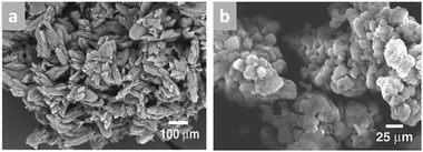 | ||
| Fig. 33 FESEM images of bulk COF-1 (a) and COF-5 (b). Reproduced with permission from ref. 4, Copyright The American Association for the Advancement of Science (2005). | ||
The stability of the framework is another factor that can be confirmed by checking the morphological stability of the material. In 2012, Banerjee and co-workers tested the chemical and water stability of two β-ketoenamine-linked frameworks, TpPa-1 and TpPa-2, using the FESEM method.67 As can be seen in the inset of Fig. 30 (left), there was no change in the morphology of TpPa-1. Both frameworks possess flower-like surface structures, which are possibly formed by aggregated gobs of petals. For TpPa-1, each petal is 1–3 μm long, 70–150 nm wide and 30–40 nm thick in size. The petals are thicker and wider for TpPa-2. The electron images confirmed the stability of the COF in boiling water, 9 N HCl and 9N NaOH for 7 days.
COFs exhibit sharp FESEM images, showing very interesting surface morphologies. Recently, this technique has been used to gain insight into the formation of different micro and nano-structures by conducting COF synthesis time-dependent studies. In 2019, the self-assembly of the hollow shuttle-shaped TPE-TAP-COF was studied at different intervals.190 The fully grown shuttle-like morphology of the COF was synthesized in 5 days; therefore, the generation of its microstructure was gradually studied after 1, 2, 3, 4 and 5 day intervals (Fig. 34a). It can be observed from the FESEM images that after 1 day, a small nanospherical assembly was present, which further agglomerated into nanorods on 2 d. These rods were about 100 nm in diameter and a few microns long. After the third day, the nanorods roughly assembled to yield a dense microcapsule. Further on days 4 and 5, the surface of the microcapsule became smoother and hollow cavities began to form inside the shuttle, which was confirmed by the TEM images (Fig. 34b). A pictorial representation of the self-assembly is depicted in Fig. 34c.
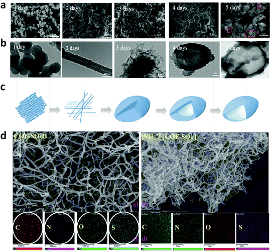 | ||
| Fig. 34 (a) FESEM and (b) TEM images of TPE-TAP-COF recorded at different intervals. (c) Mechanism for the formation of COF hollow microshuttle. (d) FESEM images (top) and EDS mapping (bottom) results of COF-SO3H (left) and [NH4]+[COF-SO3−] (right). Reproduced with permission from: (a–c) ref. 190, Copyright The Royal Society of Chemistry (2019) and (d) ref. 191, Copyright 2019 Creative Commons CC by license. | ||
Moreover, the FESEM images of various microcrystals of NPN-1, NPN-2, NPN-3, COF-300, COF-303, LZU-59 and LZU-111 were measured, which revealed the formation of single-crystalline COFs.6,88
Energy-dispersive X-ray spectroscopy (known as EDX/EDS/EDXS/XEDS) is another analytical technique that accompanies electron microscopy, which is widely used for elemental analysis of the sample. To verify the elements present in the covalently-bonded organic porous framework, chemical characterization is performed, which mostly gives the electronic image with the % of elements present in it and their mapping. An example of this is COF-SO3H and [NH4]+[COF-SO3−], where their SEM images and EDX mapping are shown in Fig. 34d.191
A few years ago, the effect of different synthetic methods on the surface morphology of the framework was studied. Banerjee and co-workers reported three distinct morphologies for the TpPa-1 COF under three different synthetic conditions.67,83,84 The dark-red COF possessed a flower-like, graphene-sheet like and ball-like surface when synthesized under solvothermal, mechanochemical and microwave irradiation conditions (Fig. 35). The flower-shaped morphology resulted from the aggregation of the sheet-like petals, which were 70–150 nm wide and 30–40 nm thick. The time and conditions required to form this distinct morphology were provided via the thermodynamically supported solvothermal method. However, when the framework was constructed by constant grinding, the 2D sheets tended to delaminate by breaking the supramolecular stacking forces. This can be seen when graphene-like layered sheets were formed instead of a flower. For the ball-like morphology with a rough surface, the diameter of each ball was ∼30 nm, which is consistent with the thickness of the flower petals formed during the solvothermal synthesis.
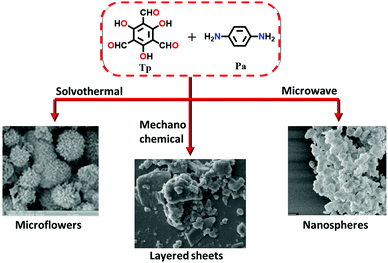 | ||
| Fig. 35 Pictorial representation of TpPa-1 COF synthesized using triformylphloroglucinol (Tp) and phenylenediamine (Pa), acquiring three different morphologies under different reaction conditions. Reproduced and adapted from ref. 67, Copyright the American Chemical Society (2012); ref. 83, Copyright the American Chemical Society (2013) and ref. 84, Copyright The Royal Society of Chemistry (2015). | ||
Similarly, Shinde et al. observed that two distinct surface patterns in TpBpy COF existed when the Tp and Bpy monomers were subjected to (a) solvothermal (120 °C, 72 h) and (b) mechanochemical (30 Hz, 90 min) conditions, respectively.192 In the high temperature vacuum environment, the small COF crystallites (100–300 nm wide) agglomerated to form fine thread-like shapes, which interweave. Conversely, the framework obtained via the mechanochemical approach formed sheets of smaller dimensions due to exfoliation by constant grinding.
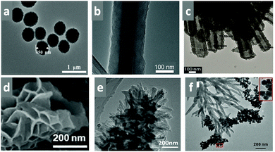 | ||
| Fig. 36 TEM images showing different surface morphologies. Reproduced with permission from: (a) ref. 186, Copyright the American Chemical Society (2019); (b) ref. 187, Copyright John Wiley and Sons (2018); (c) ref. 193, Copyright The Royal Society of Chemistry (2015); (d) ref. 188, Copyright Elsevier (2019); (e) ref. 138, Copyright The Royal Society of Chemistry (2021) and (f) ref. 189, Copyright the American Chemical Society (2017). | ||
A distinctive surface morphology fabricated from a flower-like surface via the self-assembly of nanosheets was reported by Das et al. in 2019. The bis(imidazole)-linked TBICOF, which was solvothermally synthesized (vide supra), sets in a uniformly ordered porous hexagonal arrangement, which could be observed by HRTEM (Fig. 37).68 During the course of the 3 day reaction, the nanosheets combine, forming a ring-like assembly, and set in a microfloral morphology with an average diameter of 150–200 nm and height of 12–15 nm. STEM (scanning transmission electron microscopy) images of the microflower surface were also taken, in which the electron beam is focussed at a wider angle and scans through the sample.
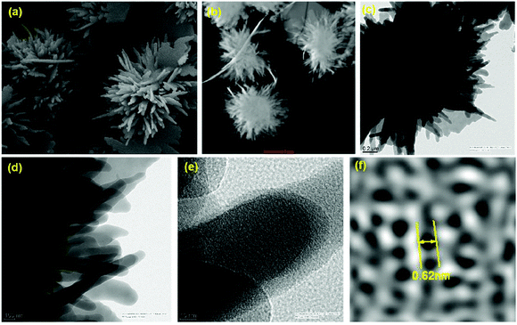 | ||
| Fig. 37 (a) FESEM image focusing on the microflower areas in TBICOF; (b) STEM image of TBICOF; (c) TEM image of TBICOF depicting microflowers; and (d–f) HRTEM images of TBICOF. Reproduced with permission from ref. 68, Copyright the American Chemical Society (2019). | ||
Previously, it was mentioned that acquiring crystallinity in a framework endowed with stability and functionalization is very complex. However, this technique helps to monitor the amorphous and crystalline nature by scanning in-depth electron images of the framework. Wang and co-workers reported an example of this, in which the amorphous-to-crystalline transformation of an Fe3O4-templated polyimine COF (a) into Fe3O4@COF(TpBD) (b) was carried out solvothermally. The HRTEM images were taken to record the reorganization of the disordered framework into well-defined and ordered microspheres (Fig. 38).194
 | ||
| Fig. 38 HR-TEM images of Fe3O4@polyimine (a) and Fe3O4@COF(TpBD) (b). Reproduced with permission from ref. 194, Copyright John Wiley and Sons (2016). | ||
The growth of microstructures from nanoparticles can be well studied by TEM and HRTEM images. An example of this is shown is Section 5.4.1, Fig. 34b. Recently, the formation of hollow tubes of the TPT-DAHQ COF with sponge-like shells, which occurred via aggregation, self-assembly and Ostwald ripening of the COF, was examined (Fig. 39).164 The solvothermally synthesized COF (see Section 4.2) investigated via a time-dependent study, where the reaction was quenched after 12, 24 and 48 h to obtain the high-resolution image. It was observed that after 12 h, very small ribbon-like nanocrystallites of about 40–50 nm width aggregated, which correspond to the π–π stacked 2D COF sheets. Maintaining high-temperature conditions for 24 h, the minute planar crystallites assembles to form dense tubules whose walls were formed by the aggregation of the ribbon-like nanocrystallites. After 48 h, an exceptional phenomenon of the Ostwald ripening process occurred, by which the crystallites present inside the hollow tubules migrated towards the outer surface to reduce their surface energy. This destroyed the tubules, and hollow microtubes were formed with rough crystallites located on their surface. At the end of the reaction after 72 h, the ribbon-like crystallites present on the outer surface of the microtubules displays a smooth sponge-like surface. The resulting tubules had an average length of 7.4 μm and average diameter of 1 μm. The average values for the outer and inner diameters of the tubules were 0.90 and 0.53 μm, respectively.
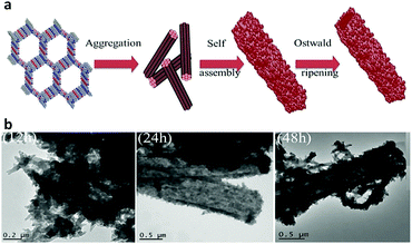 | ||
| Fig. 39 (a) Expected mechanism for the formation of the hollow microtubular TPT-DAHQ COF having sponge-like shells. (b) TEM images of the hollow microtubular TPT-DAHQ COF having sponge-like shells, measured after reaction times of 12, 24, and 48 h. Reproduced with permission from ref. 164, Copyright John Wiley and Sons (2019). | ||
In addition to images, the bulk phase purity of powdered frameworks has also been studied using selected area electron diffraction (SAED). This technique is beneficial to observe the diffraction spots, and thus gives information about the order of the framework. Moreover, using fast Fourier transformation (FFT), the d-spacing between the two planes can be closely measured. Consequently, the high and low-angle grain boundaries can be identified, providing that the framework has exceptionally high crystallinity, stability and rigidity. This type of study was performed by Lotsch and co-workers on TTT-COF and TTI-COF.170 Besides, phenomena such as twinning, or some framework defects can also be detected.
It is well known that TEM usually produces flat 2D images, which lack some features compared to FESEM, given that a 3D image of the sample can be obtained. However, a crucial study using 3D diffraction tomography (3D-EDT) can also be conducted using the TEM technique (Fig. 40). 3D-EDT is basically an extension of the regular TEM, in which the sample is rotated or tilted at different angles around its center to obtain a three-dimensional image. An example of this was reported in 2016 by Yaghi and co-workers using a rare woven COF, COF-505.195
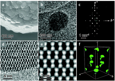 | ||
| Fig. 40 Morphology and electron microscopy studies of COF-505. (a) Crystallites aggregated on a crystalline sphere observed by SEM. (b) TEM image of a single sub-mm crystal used for 3D-EDT. (c) 2D projection of the reconstructed reciprocal lattice of COF-505 obtained at 298 K from a set of 3D-EDTdata. (d) HRTEM image of COF-505 taken with the [1−10] incidence. (e) 2D projected potential map obtained by imposing pgg plane group symmetry. (f) Reconstructed 3D electrostatic potential map (threshold, 0.8). Reproduced with permission from ref. 195, Copyright The American Association for the Advancement of Science (2016). | ||
The FESEM and TEM images showed that spheres with a diameter of 2 mm were formed through the agglomeration of small crystallites with a size of ∼200 nm. The 3D-EDT data was obtained by tilting the sample and the electron beam in the range of −41.3° to +69.1° with a beam-tilt step of 0.2°. According to the acquired tomography data, the C-centred orthorhombic lattice was constructed with cell parameters of a = 18.9 Å, b = 21.3 Å, c = 30.8 Å, and V = 12399 Å3.
A rarely used technique for the structure determination of COFs using the TEM analytical method is 3D rotation electron diffraction (RED). In this technique, the fairly small-sized single-crystalline imine-linked COF-320 was evenly spread on a carbon-coated Cu grid via the drop-casting method. Thereafter, the 3D-RED data was collected in SAED mode at 298 K with the diameter of the chosen aperture greater than the crystal size. The ED images were taken by tilting the crystal base in the range of −35.00° to +25.10° with a beam-tilt step of 0.4°. The data was processed and detailed structural information was obtained, indicating the tetragonal I![[4 with combining macron]](https://www.rsc.org/images/entities/char_0034_0304.gif) 2d space group with the dia-c9 topology (Fig. 41a).89 The image of the reconstructed reciprocal lattice from 3D-RED data is shown in Fig. 41b-d.
2d space group with the dia-c9 topology (Fig. 41a).89 The image of the reconstructed reciprocal lattice from 3D-RED data is shown in Fig. 41b-d.
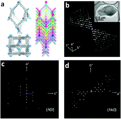 | ||
| Fig. 41 Morphology and electron diffraction of COF-320. (a) SEM image of the aggregation of crystallites. (b) 3D reciprocal lattice of COF-320 reconstructed from the RED data collected from a crystal of 1.0 × 0.5 × 0.2 μm3 (inset). (c) (h0l) and (d) (hk0) slices cut from the reconstructed reciprocal lattice. Reproduced with permission from ref. 89, Copyright the American Chemical Society (2013). | ||
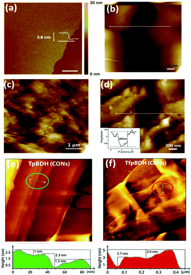 | ||
| Fig. 42 AFM image and height profile of (a) hcc-COF film (scale bar = 1 μm), (b and c) COFDAAQ-BTA-3DG composite, (d) scratched COFDAAQ-BTA-3DG composite and the corresponding section profile, (e) TfpBDH-CONs and (f) TpBDH-CONs with the corresponding height profiles below (the height profiles filled in red and green colour were measured along the corresponding tracks inside the circle shown in the AFM images). Reproduced and adapted with permission from: (a) ref. 163, Copyright 2019 reprinted under the terms of Creative Commons Attribution 4.0 International license; (b–d) ref. 183, Copyright the American Chemical Society (2015) and (e and f) ref. 149, Copyright The Royal Society of Chemistry (2015). | ||
5.5 X-ray photoelectron spectroscopy (XPS)
This technique is employed to determine the composition of elements, which helps in characterizing the bulk structure of materials. COFs are composed of light elements, such as B, C, N, O, S, P and Si, and thus the peaks in an XPS spectrum, which gives a plot of the number of electrons vs binding energy, directly indicate the identity and amount of an element present in the framework. The XPS peaks also display the subshell (1s, 2s, 2p, 3s, etc.) from which the electron is ejected when the X-ray beam falls on it. In addition, the bonding between the two monomer units can also be determined using this spectroscopic technique. A few N-rich frameworks characterized by this method are discussed below.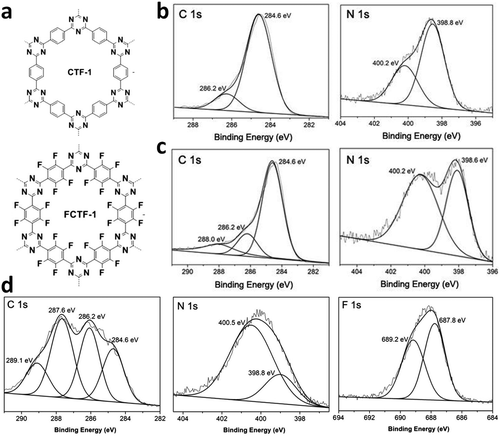 | ||
| Fig. 43 (a) Structures of CTF-1 and FCTF-1. (b–d) C1s, N1s and F1s XPS spectra of triazine-linked COFs, CTF-1, CTF-1–600 and FCTF-1, respectively. Reproduced with permission from ref. 120, Copyright The Royal Society of Chemistry (2013). | ||
By introducing electron-withdrawing fluorine atoms in the CTF-1 moiety, the degree of polymerization was reduced. This was confirmed by the XPS spectra of FCTF-1 (fluorinated CTF-1), where the peak intensity of the uncondensed N-atom at 400.5 eV increased significantly in comparison to that at 398.8 eV, which was originally assigned to the triazine nitrogen. Furthermore, the chemical nature of the C and F atoms was also explained using this technique given that the C1s spectrum can be deconvoluted into four peaks as follows: two usual peaks at 284.6 eV (for aromatic sp2-C) and 286.2 eV (triazine-ring carbon) and two arising from F-substitution at 287.8 eV (semi-ionic C–F bond) and 289.1 eV (covalent C–F bond). In the F1s spectrum, two signals assigned to partial-ionic (687.8 eV) and covalent C–F bonds (689.2 eV) were observed. In the N1s XPS spectrum, FCTF-1 COF displays more striking peaks of nitrile in comparison to CTF-1, which clearly indicates that the fluorine-substituted precursor reduces the degree of polymerization in the framework.
Later, in 2015, the conversion of the triazine-linked framework from a lower m-CTF net to higher dimensional PTF net was reported, and the transformation was witnessed by the deconvoluted XPS N1s spectral peaks.121 The m-CTF net displays the two basic C1s peaks and one N1s peak at ∼284.4, ∼286.3 and ∼398 eV, respectively, where the latter peak suggests the existence of only one type of pyridyl nitrogen in the triazine ring. Conversely, the 3D porous triazine framework, namely PTF, that was synthesized at an elevated temperature showed two extra peaks in the N1s XPS spectrum, which were assigned to pyrrolic nitrogen at ∼399.5 eV and quaternary nitrogen at ∼400.8 eV.
The XPS spectra of SCOF-LZU-1 depict the standard peaks for the carbon and nitrogen atoms of the imine bond in the C1s and N1s spectra at 285.1 and 398.6 eV, respectively (Fig. 44a). In addition, an extra peak in both the spectra was observed at 284.4 eV for the SCOF backbone and HOPG substrate and at 399.7 eV for the nitrogen from the unreacted diamine unit.101
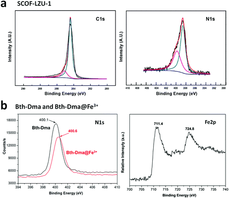 | ||
| Fig. 44 (a) C1s and N1s XPS spectra of imine-linked SCOF-LZU-1. (b) N1s and Fe2p XPS spectra of hydrazone-linked Bth-Dma and Bth-Dma@Fe3+ COFs. Reproduced with permission from: (a) ref. 101, Copyright the American Chemical Society (2013) and (b) ref. 141, Copyright the American Chemical Society (2019). | ||
This year, a similar example was reported, where XPS measurement verified the Fe(III) ion sensing by the Tfpa-Mth COF, forming Tfpa-Mth COF@Fe3+.134 Before the sensing experiment, the Tfpa-Mth COF exhibited two peaks at 401.17 and 400.17 eV for C–N (unreacted Tfpa and Mth) and C![[double bond, length as m-dash]](https://www.rsc.org/images/entities/char_e001.gif) N (imine bond), respectively, in its N1s XPS spectrum. There was a decrease in the binding energy values after binding to the Fe3+ ions (400.88 and 399.90 eV), suggesting the successful fixation of Fe3+ ions to the wall of the pores. Moreover, the O1s XPS spectrum of the COFs also showed the BE values of 531.40 and 531.11 eV before and after the sensing experiment, respectively, which support the detection of Fe ions. In the Fe2p spectrum, the characteristic signals at 712.01 and 725.07 eV were assigned to the binding energies of Fe 2p3/2 and Fe 2p1/2, respectively.
N (imine bond), respectively, in its N1s XPS spectrum. There was a decrease in the binding energy values after binding to the Fe3+ ions (400.88 and 399.90 eV), suggesting the successful fixation of Fe3+ ions to the wall of the pores. Moreover, the O1s XPS spectrum of the COFs also showed the BE values of 531.40 and 531.11 eV before and after the sensing experiment, respectively, which support the detection of Fe ions. In the Fe2p spectrum, the characteristic signals at 712.01 and 725.07 eV were assigned to the binding energies of Fe 2p3/2 and Fe 2p1/2, respectively.
For COF-DB and COF-DT, three intense peaks were observed in their C1s, O1s and N1s spectra, which were comprised of multiple signals depicted from the high-resolution XPS spectra. It was observed that C1s and O1s show similar binding energy values for both COFs. Conversely, the N1s spectra showed peaks at 399.2 and 398.4 eV, which indicate the presence of a C–N![[double bond, length as m-dash]](https://www.rsc.org/images/entities/char_e001.gif) C center corresponding to the picoline and the triazine-cores for COF-DB and COF-DT, respectively.131
C center corresponding to the picoline and the triazine-cores for COF-DB and COF-DT, respectively.131
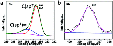 | ||
| Fig. 45 (a) C1s and (b) N1s XPS spectra of 2DPPV COF. Reproduced with permission from ref. 158, Copyright The Royal Society of Chemistry (2016). | ||
To gain insight into the chemical structure of the metal ions in the dioxin-linked Ni/Co/ZnPc-TFPN COF (Fig. 46),171 the XPS of NiPc-TFPN COF was considered. It showed peaks at 855.7 eV for Ni2p3/2 and 873.0 eV for Ni2p1/2 in the Ni2p XPS spectrum. This corresponds to the +2 oxidation state of Ni. Similarly, the Co2p and Zn2p XPS spectra are also indicative of divalent metal ions.
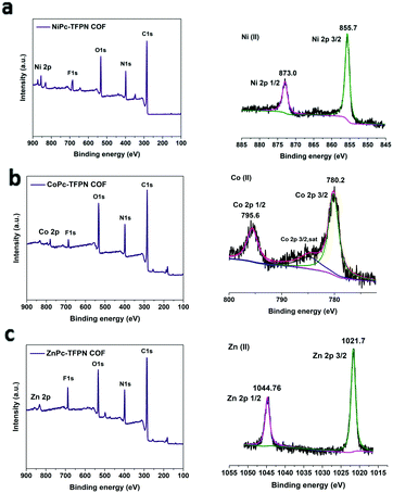 | ||
| Fig. 46 Survey scan and high-resolution XPS profiles of (a) NiPc-TFPN COF, (b) CoPc-TFPN COF and (c) ZnPc-TFPN COF. Reproduced with permission from ref. 171, Copyright John Wiley and Sons (2021). | ||
5.6 Gas sorption
Porous frameworks have been known for a long time and proven to be potent candidates for a number of applications. Covalently bonded organic frameworks exhibit large surface areas with multiple types of micro-, meso- and macropores, which are tailored by maintaining their topology (vide supra). The surface area, pore volume and pore size of these porous materials can be calculated from the gas adsorption–desorption isotherms using the multi-layered Brunauer–Emmett–Teller (BET) adsorption method. There are six different types of adsorption isotherms, as shown in Fig. 47,196 which are classified as type I to VI and reveal information about the nature of sorption, type of pores depending on their size, adsorption capacity, etc. The isotherms are obtained via the physical adsorption of inert and non-polar gases (N2 and Ar) in the pores of the material. The type I isotherm is specifically exhibited by microporous materials (pore size < 2 nm), indicating limited gas uptake due to monolayer adsorption. It is specifically attributed to the physisorption of nitrogen or argon on porous solids.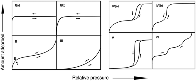 | ||
| Fig. 47 Different types of BET adsorption isotherms. Reproduced and adapted from ref. 196 (no permission required), Copyright IUPAC (2015). | ||
The type II and type III isotherms are particularly associated with non-porous or microporous materials, where the size of their pores is >50 nm. The type II sorption curve reveals the unrestricted mono- and multi-layered adsorption of inert gas over the surface, whereas the type III isotherm is restricted to only multi-layer adsorption. The type IV and V isotherms represent a hysteresis loop, where multilayer adsorption occurs on the mesoporous surface (pore size 2–50 nm), suggesting the presence of mesopores in the material. The type VI isotherm suggests stepwise multilayer adsorption on an enormously homogeneous non-porous solid surface.
Various interesting examples of highly porous COFs with different linkages are discussed in this section, indicating their BET surface areas, number of pores, size and volume and the effect of functionalization.
It is very interesting to note that the highest BET surface area reported in COF chemistry is for the boronic ester-linked DBA-3D COF-1 with a value of 5083 m2 g−1. Its surface area was reduced down to 4763 m2 g−1 upon metallation of its framework.197
A distinctive example for the effect of alkyl chain length in boronic ester-linked COFs, namely COF-18 Å (R = H), COF-16 Å (R = Me), COF-14 Å (R = Et) and COF-11 Å (R = n-Pr), on the BET surface is shown in Fig. 48a.198 For an increase in the chain length from COF-18 Å to COF-11 Å, the surface area is drastically reduced, having SABET values of 1263, 753, 805 and 105 m2 g−1, respectively, based on the type-I N2 gas adsorption isotherms at 77 K. The pore diameter decreased from 18 Å to 11 Å, as denoted by the name of the COF. It must be noted that the ethyl-substituted framework exhibits a slightly greater surface area in comparison to the methyl-substituted COF due to the rotation of the ethyl group, which provides a large surface area to adsorb nitrogen. A similar trend was observed for pore volume.
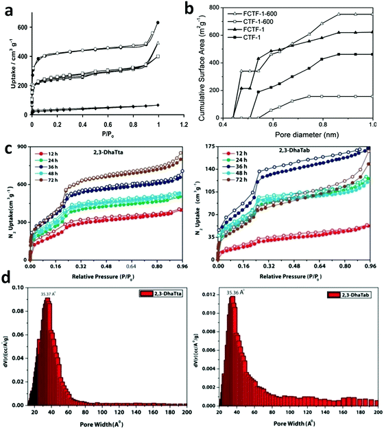 | ||
| Fig. 48 Adsorption isotherm of (a) boronic ester-linked COFs, COF-18 Å, COF-16 Å, COF-14 Å and COF-11 Å, (b) triazine-linked COFs, CTF-1, CTF-1–600, FCTF-1 and FCTF-1–600 and (c) imine-linked COFs, 2,3-DhaTta and 2,3-DhaTab with their pore size distribution (d). Reproduced with permission from: (a) ref. 198, Copyright John Wiley and Sons (2008); (b) ref. 120, Copyright The Royal Society of Chemistry (2013) and (c and d) ref. 79, Copyright John Wiley and Sons (2016). | ||
The triazine-linked CTF series, viz. CTF-1, CTF-1–600, FCTF-1 and FCTF-1–600, was analyzed via Ar sorption isotherms at 87 K to study the effect of temperature conditions on their surface area (Fig. 48b).120 Both CTF-1 and FCTF-1 exhibited type-I sorption isotherms, with the microporous cumulative surface area of 461 and 623 m2 g−1, respectively. According to non-local density-functional theory (NLDFT), it was found that CTF-1 exhibits a pore size of 0.5 nm, whereas FCTF-1 has two pores, 0.46 and 0.54 nm. On increasing the reaction temperature from 400 to 600 °C for the synthesis of CTF-1–600, a type IV sorption isotherm was observed, indicating that mesopores, was obtained with a surprisingly low surface area of ∼157 m2 g−1. However, FCTF-1–600 showed a type I isotherm with a surface area of 752 m2 g−1. The reduced pore size ∼0.59 nm for FCTF-1–600 is possibly due to the F-atom substitutions in its framework.
This technique has also been utilized to monitor the significant changes within the framework caused due by different structural packing. On example was reported for the imine-linked 2,3-DhaTta and 2,3-DhaTab COFs (Fig. 48c and d), respectively. These two frameworks are different in terms of the π–π packing among the 2D layers (see Section 3.2.1). Specifically, 2,3-DhaTta contains planar triazine-cored linker units, which create high crystallinity and high BET surface area in the framework. Its N2 adsorption isotherm depicts a type-IV curve, indicating a mesoporous framework with a surface area of ∼1700 m2 g−1. Conversely, 2,3-DhaTab possesses a low surface area of ∼413 m2 g−1, which is attributed to its reduced planarity and crystallinity because of its twisted phenyl-cores. This was further confirmed by the PXRD technique (vide Section 5.3.1). Moreover, a time-dependent study was conducted on both frameworks at 12, 24, 36, 48 and 72 h, showing the framework building.79
The study of gas sorption and BET surface area is also helpful to support dimensionality changes and the extent of interpenetration. The pair 2D ILCOF-1 and 3D-ILCOF-1, which use planar C4-symmetric and non-planar Td-symmetric aldehyde monomers, respectively, is a great example. According to the Ar sorption isotherm, ILCOF-1 has a type IV curve with a sharp uptake in the range of P/P0 = 0.05–0.15, indicating the mesoporous nature of this material, whereas the N2 isotherm of the 3D framework depicts uptake below P/P0 = 0.1, indicating its microporous cavities (Fig. 49a and b), respectively. Their BET surface areas are 2723 and 517 m2 g−1 with a pore volume of 1.21 and 0.36 cm3 g−1, respectively, which was calculated using the NLDFT method. The reason for the drastic reduction in the various surface parameters is the high degree of interpenetration in 3D-ILCOF-1. Moreover, the two isoreticular COFs, 3D-ILCOF-2 and 3D-ILCOF-3, show a slightly higher adsorption uptake in comparison to 3D-ILCOF-1.85,122
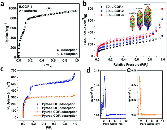 | ||
| Fig. 49 Adsorption isotherms of imine-linked COFs (a) ILCOF-1 and (b) 3D-ILCOF-1/2/3, and (c) hydrazone-linked Pythz-COF and Pyurea-COF with their pore-size distribution curves (d and e). Reproduced with permission from: (a) ref. 122, Copyright John Wiley and Sons (2013); (b) ref. 85, Copyright the American Chemical Society (2018) and (c–e) ref. 138, Copyright The Royal Society of Chemistry (2021). | ||
The hydrazone- and urea-based COFs, Pythz and Pyurea COF, display quite different N2 sorption behaviours at 77 K (Fig. 49c).138 In the case of the Pythz COF, a distinctive combination of type I and II isotherms was observed, indicating its both micro and mesoporous nature. Conversely, the Pyurea COF shows a type I adsorption isotherm, indicating its purely microporous structure. The BET surface area/pore volume of these frameworks were 1571/1.21 and 1016/0.53 m2 g−1/cm3 g−1, respectively. By using NLDFT calculations, the pore size distribution confirmed two pore sizes (2.34 and 1.36 nm) for Pythz COF and one pore size (1.48 nm) for the Pyurea COF (Fig. 49d and e), respectively.
Two COFs, amial-COF-1 and aminal-COF-2, show similar a surface area of ∼1168 m2 g−1 but different pore volumes of 0.65 and 0.89 cm3 g−1, respectively, at P/P0 = 0.99. By using quenched solid-state density functional theory (QSDFT), the calculated pore size distributions (Fig. 50) show that both COFs have two types of micropores, i.e., at 5.2 and 8.2 for aminal-COF-1 and 5.4 and 8.2 for aminal-COF-2 (Fig. 50).38
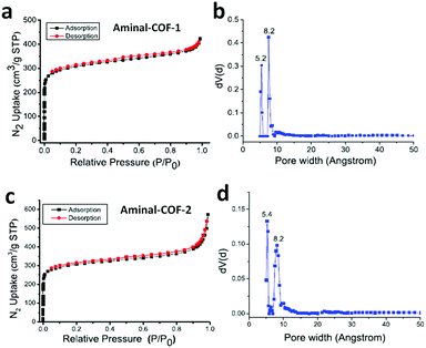 | ||
| Fig. 50 Adsorption isotherm of (a) aminal-COF-1 and (c) aminal-COF-2 with their pore-size distribution using QSDFT (b and d), respectively. Reproduced with permission from ref. 38, Copyright the American Chemical Society (2019). | ||
It has been seen that by reticulation of the framework, the specific surface areas and pore dimensions change. This can be numerically compared by the BET surface area and pore sizes of the different COFs shown in Table 3.
5.7 Thermogravimetric analysis (TGA)
One of the major reasons for the development of COFs is to generate rigid and robust materials that can withstand high thermal conditions. TGA is used to detect the maximum temperature up to which the polymer is stable, where the percentage weight loss of the framework over a certain temperature range (∼30–600 °C) is calculated. This also provides an indication for the presence of solvent molecules used during the synthesis and/or any residual unreacted monomers within the framework lattice. Accordingly, the as-synthesized COF sample is fully activated at high temperature (∼100–120 °C) under vacuum, and then subjected to TGA analysis under N2 environment.The triazine-connected crystalline framework show very high thermal stability in the presence of air. For example, CTF-0 is relatively more stable than CTF-1 up to 600 °C, which indicates the rich nitrogen content and good cross linking density in CTF-0 compared to CTF-1.19 It should be noted that only triazine-based COFs exhibit impressive thermal stability in realistic conditions, i.e., in the presence of an oxygen atmosphere. For all other linkages, the TGA is recorded under an inert atmosphere of N2 gas due to their low stability.
Both activated β-ketoenamine-linked TpPa-1 and TpPa-2 are thermally stable up to 350 °C, indicating the absence of guest molecules within their pores. However, with a further increase in temperature, there is a large weight loss (TpPa-1: 40% and TpPa-2: 50%), which is attributed to their structural decomposition.67
The TGA analysis of hydrazone-linked COFs, such as NUS-50 and NUS-51, showed their thermal stability up to 350 °C.130 The aminal-linked COFs, namely aminal COF-1 and aminal COF-2, are comparatively less thermally stable. Their TGA data revealed virtually no weight loss up to 200 °C, and only 10% weight loss was observed at around 320 °C.38
The stability changes during post-synthetic modification of the robust organic framework can also be monitored using this technique. The COF TpBD(NO2)2 upon reduction to form TpBD(NH2)2 showed a similar weight loss profile (weight loss was observed at 450 °C, suggesting the decomposition of the framework), indicating that there were no distinct structural changes.146 The TGA analysis of COF-701 shows no significant weight loss before 400 °C under a nitrogen atmosphere, proving its exceptional stability.160 A rare example of the highly crystalline imine-linked 2D ILCOF-1, which remains stable up to 400 °C even under aerobic conditions, was also reported.122
The above-mentioned characterization techniques are greatly helpful to discover the attractive properties of the N-rich frameworks and guide their use for suitable and potential applications.
6. Luminescence and sensing
6.1 Luminescence
In this section, we introduce and discuss a few phenomena that are essential to describe the luminescence properties of COFs and explain their mechanism of action in various applications in Section 6.2.Furthermore, when the number of consecutive phenyl rings increases within a unit, it loses planarity, giving rise to an anomalous trend. For instance, Perepichka and co-workers reported two different COFs, namely 3PD and 3BD, synthesized from a combination of a tritopic-b-ketoenol and two different aromatic amine units, i.e., phenylenediamine (PD) and biphenyldiamine (BD).201 The calculated band gap for the less p-conjugated COF system, 3PD, is 2.03 eV, which, on the contrary, increased to 2.19 eV when the conjugation within the framework increased, i.e., in 3BD COF. This is attributed to the loss of planarity between the phenyl rings of the linker BD.
A similar example was reported by Jiang et al., examining the details of π-conjugation and its effect on the luminescent properties of COF materials.202 A pyrene-containing C4-symmetric monomer unit, tetraformylphenylpyrene (TFFPy), was used to synthesize three sp2-carbon conjugated 2D- COFs, viz., sp2c-COF, sp2c-COF-2 and sp2c-COF-3, via their combination with C2-symmetric phenyl, biphenyl and triphenylacetonitrile units (PDAN, BPDAN and TPDAN), respectively. In accordance with the theory, there was a bathochromic shift (Δλ higher) in the emission spectra of TFFPy and three COFs as the monomer emits blue light, whereas the COFs emit in the bright red region (orange, bright yellow, dull and yellow). Conversely, the absorbance and emission spectra of sp2c-COF-2 and sp2c-COF-3 were more blue-shifted despite their higher conjugated frameworks. This is due to the deplanarization of the monomeric unit when more phenyl rings are incorporated within one row. Therefore, a hypsochromic shift was seen, corresponding to a high transition energy band gap.
The AIE effect has been observed in covalent organic frameworks incorporating AIEgens as monomeric units. Since the COF layers are stacked on each other via non-covalent interlayer π-interactions, the fluorescent moieties present within the framework form excimers, leading to the dissipation of energy via a non-radiative pathway. This eventually restricts the luminescence in COFs due to the ACQ effect. To turn off this process, aggregation-induced emission (AIE) becomes functional, where a radiative emission competes with the faster non-radiative process to impede intramolecular rotations (RIR), vibrations (RIV) and molecular motions (RIM).
On coating the 3D-TPE-COF, which was reported by Ding et al., on a regular blue LED, bright white light was emitted, which makes the COF a white light-emitting diode (WLED).206 The photoluminescence properties of the TPE monomer were studied when it was incorporated inside the framework. It was observed that the model compound of TPE-COF exhibited very weak yellow-green emission with a low photoluminescent quantum yield (ca. 6.6%), whereas the COF itself emitted bright yellow light (λmax = 543 nm) with a much higher quantum yield (ca. 20%). This is due to the restricted intramolecular rotation (RIR) of the phenyl ring rotators alongside the olefinic bond in TPE when placed in the rigid skeletal three-dimensional framework.
Likewise, the 2D TPE-Ph-COF contains a similar TPE-based core, which shows strong luminescence emission in its aggregated state. A boronic ester-linked COF was reported by Jiang and co-workers in 2016, elaborating the emission of bright blue color at 500 nm when excited at 390 nm (Fig. 52). The small COF crystallites from a well-defined belt-like shape with an average size of 4 μm, the formation of which was monitored by time-dependent morphology growth.29
 | ||
| Fig. 52 (a) Structure of TPE-Ph-COF with kgm topology. (b) Fluorescence spectra of the TPE model compound (black) and the TPE-Ph COF (blue). Fluorescence microscopy images of TPE-Ph COF samples prepared at different reaction times of (c) 3 days, (d) 10 days, (e) 20 days, and (f) 30 days (inset image showing an enlarged view of the belts). Reproduced with permission from ref. 29, Copyright the American Chemical Society (2016). | ||
Other examples of COFs containing TPE AIEgens are SIOC-COF-x (x = 1, 2, 5, and 6),207,208 4PE-xP-COF (x = 1, 2, and 3) and 4PE-TT27 NUS 30–32209 and COF-DHTA, DETA and DBTA, where the terephthaldehyde unit is substituted with hydroxyl, ethoxy and butoxy groups, respectively.210
The pyrene moiety has also attracted extensive attention as an AIEgen when utilized as a monomer in COFs. For instance, Jiang and co-workers reported HHTP-PDBA-COF constructed via the [C3 + C2] polycondensation of hexahydroxytriphenylene (HHTP) and pyrenediboronic acid (PDBA).211 A strong emission at 474 nm from the pyrene moieties was observed when packed in an eclipsed fashion. One year later, the same group synthesized 2D polypyrene sheets named PPy-COF via the self-condensation of PDBA under solvothermal conditions.17 Due to the layer alignment of the pyrene units in the framework, excimer formation occurred, leading to a strong luminescence emission at 484 nm.
Later, Crowe et al. reported Py-DBA-COF-1 and Py-DBA-COF-2, which were synthesized via the condensation reaction of two different dehydrobenzoannulene units, DBA[12] and DBA[18], with pyrenediboronic acid, respectively.212 The DBA[12] and [18] units are planar, π-conjugated emissive macrocycles, where 12 and 18 indicate the number of carbon atoms within their triangular pores. A mixed variant COF using DBA[12] and [18] and PDBA was also synthesized, namely Py-MV-DBA-COF. It was found that the AIE effect of the DBA units resulted in a strong emission property for all the COFs. However, a huge red-shifted emission was observed for COF-1 (530 nm) and the mixed variant COF (528 nm) with respect to COF-2 (483 nm), which is ascribed to the fact that the DBA[12] unit embedded in the framework shows symmetry-forbidden transitions in its ground-state. This leads to the dominant excited-state properties of Py-DBA-COF-1 and Py-MV-DBA-COF.
A few more pyrene-containing COFs possessing the AIE effect have been reported in the literature, viz., A-TEBPY-COF, A-TENPY-COF, A-TEPPY-COF,213 3D-Py-COF,46 Car-ETTA-COF, TFFPy-ETTA COF,214 COF-JLU-2x (x = 3, 4, 5),215 Per-Py-COF.216
Recently, various COFs have been reported in which free –OH and –NH2 groups are present near the proton acceptor sites, such as imine or triazine linkages or C![[double bond, length as m-dash]](https://www.rsc.org/images/entities/char_e001.gif) O groups, which leads to intramolecular hydrogen-bond interactions and turns on the ESIPT process. The monomeric units exploited to make highly luminescent COFs following the ESIPT mechanism are shown in Fig. 54.
O groups, which leads to intramolecular hydrogen-bond interactions and turns on the ESIPT process. The monomeric units exploited to make highly luminescent COFs following the ESIPT mechanism are shown in Fig. 54.
This photochemical switching process involves four states, i.e., electronic ground state and first excited state of enol and keto forms, denoted by E (S0) and K (S0) and E* (S1) and K* (S1), respectively. The enol form of the ESIPT fluorophore is seen at the E (S0) level, which after photon absorption gets excited to the E* (S1) level. At this stage, there is an increase in the acidic character in the H-bond donor moiety and basicity in the H-bond acceptor site, which causes an extremely rapid ESIPT transition from the excited enol to keto form at the rate of ∼1012 s−1. After radiative decay from this stage (K* (S1) to K (S0)), a reverse proton transfer (RPT) possibly happens, giving the original enol form. A detailed scheme of this process is shown in Fig. 55.
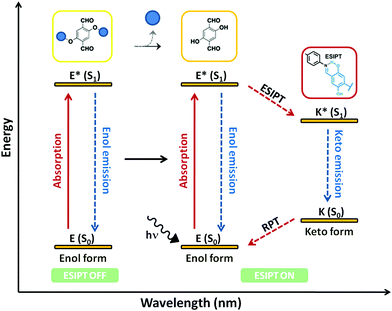 | ||
| Fig. 55 General mechanism showing the dual-enol and keto emission in the excited-state intramolecular proton transfer (ESIPT) process in COFs. | ||
The ESIPT mechanism has been widely studied with a large variety of organic and inorganic molecules and polymers.218–222 During this study, it has been found that the surrounding environment of these materials highly affects their luminescence property. For instance, polar solvents form additional hydrogen bonds with the molecules in their enolic form, competing with the intramolecular hydrogen-bond formation. This ceases the ESIPT pathway from the enol to keto form, hence inhibiting the process. Thus, organic solvents have been largely used as a medium to produce and examine the luminescence caused by the excited-state intramolecular proton transfer mechanism.218
An example of a COF (IISERP-COF-7) showing dual-emission through the ESIPT mechanism was reported by Halder et al. (Fig. 56).223 It was found to be a white-light emitter in various solvents. The free –OH groups on the C3-unit form intramolecular hydrogen-bonding with the –CH![[double bond, length as m-dash]](https://www.rsc.org/images/entities/char_e001.gif) N– linkages and strong enol–keto tautomerism was observed. The appropriate geometry of the –OH group and its orientation towards the imine linkage turns on the ESIPT mechanism.
N– linkages and strong enol–keto tautomerism was observed. The appropriate geometry of the –OH group and its orientation towards the imine linkage turns on the ESIPT mechanism.
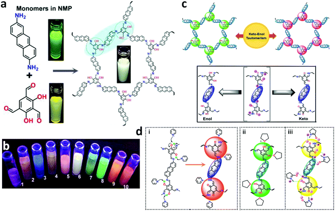 | ||
| Fig. 56 (a) Dispersions of the monomers and COF suspended in NMP pictured under a UV lamp. (b) COF dispersion in different solvents placed under a UV lamp. Codes: 1, THF; 2, dioxane; 3, glyoxal; 4, pyridine; 5, DMA; 6, NMP; 7, ethanol; 8, formamide; 9, picoline; and 10, DMF. (c) Proposed schematic representation of keto-enol tautomerism in the resorcinol unit of the COF (top). The repeating unit of the COF transforms from the keto to enol form and vice versa through a polarizable transition state (bottom). (d) (i) Proton abstraction mechanism in pyridine, which stabilizes the keto-form; (ii) hydrogen bonding by THF stabilizes the enol-form; and (iii) polarized NMP stabilizing the intermediate keto–enol form. Reproduced with permission from ref. 224, Copyright the American Chemical Society (2018). | ||
However, this dual-emission is highly disturbed by polar N-donor (pyridine, picoline, and acetonitrile) and O-donor (THF, dioxane, methanol and ethanol) solvents. It has been observed that highly basic N-donor solvents help in proton transfer from the enolic to keto form, whereas the enol form predominates when O-donor solvents are employed as the medium. In the latter case, the phenolic hydrogens of the resorcinol moiety are sandwiched between the O-atom of the solvent and phenolic oxygen.
The combination of an ESIPT and ICT system responsible for dual-emissive covalent organic frameworks was reported by Yan and co-workers.222 The TzDa-COF contains a triazine docking site and an intramolecular hydrogen-bonding site. Upon excitation at 365 and 425 nm in an ethylacetate solution, the TzDa COF exhibits fluorescence emissions at 500 and 590 nm. The phenomenon of ICT was observed in the Tz moiety, where charge transfer from the donor phenyl group and electron-deficient triazine center occurs, showing an emission at 500 nm. The emission at 590 nm corresponds to the ESIPT effect due to the presence of a proton donor –OH group and a proton acceptor –CH![[double bond, length as m-dash]](https://www.rsc.org/images/entities/char_e001.gif) N– bond in the Da moiety. Moreover, the effect of aqueous medium on the dual-luminescence emission made the TzDa-COF capable of sensing trace water molecules in organic solvents. It was observed that an increase in water content from 0.6 to 3.2 wt% blocked the ICT process by forming additional hydrogen bonding between the water and triazine nitrogens. Conversely, the increased interactions of the water molecules with the Da moiety change its excited-state form and increase the corresponding luminescence intensity at 590 nm.
N– bond in the Da moiety. Moreover, the effect of aqueous medium on the dual-luminescence emission made the TzDa-COF capable of sensing trace water molecules in organic solvents. It was observed that an increase in water content from 0.6 to 3.2 wt% blocked the ICT process by forming additional hydrogen bonding between the water and triazine nitrogens. Conversely, the increased interactions of the water molecules with the Da moiety change its excited-state form and increase the corresponding luminescence intensity at 590 nm.
A unique example was reported by Loh and co-workers, where they exploited the inter and intralayer hydrogen bonding in 2D stacked COF sheets to induce emissive properties in the framework.224 For this, a hydrazone-based non-emissive building unit with various functionalities substituted on it was employed, named 2,5-disubstituted terephthalohydrazide (DHzDR, R = Me, All, and Pr). It was proposed that due to the free intramolecular bond rotations, the monomeric units do not emit. The moiety binds with different trialdehydes, such as benzene-1,3,5-tricarboxaldehyde (Tf) and tri(4-formylphenyl)benzene (TFPB), leading to the formation of 2D COFs with face-to-face stacked sheets, which tend to form interlayer hydrogen bonds between the free –NH groups of the hydrazide moiety in one layer with C–O–C sites in the other layer. Thus, the monomers cease their rotational motion, leading to strong quenching via the AIE-effect. Moreover, the ESIPT mechanism was also seen in the framework where dual-emission is caused by intralayer hydrogen bond formation between the –NH and imine linkage located at the proximal ends. Thus, both single- and dual-emission can be seen within a molecule via two different mechanisms.
In this context, COFs such as COF-4-OH225 and PEG-COF-42226 show significant dual-emission by rapid intramolecular proton transfer from the enolic excited state to the ketonic excited state and have been explored for the ESIPT mechanism. Close proximity of the proton donor and acceptor sites, solvent environment, etc., are essential factors that make the ESIPT process possible.
This aforementioned knowledge has pushed the sensing-based study of covalent organic frameworks forward and these materials have been widely exploited to detect various analytes, such as nitroaromatic explosives, various toxic anions and metal ions, volatile small molecules such as organic or inorganic solvents, and biosensing. In this field, it is exciting when COFs are utilized to sense different pH in aqueous media and for thermal sensing.
where r is the distance between the fluorescent donor (D) and quencher/acceptor (A), R0 is the Förster distance and τD is the lifetime of the donor in the absence of energy transfer.
This mechanism is widely seen in fluorescent-active COFs, and the potential candidates for sensing various analytes are described in the next sub-section.
6.2 Sensing
In 2012, the first melamine-based porous organic framework, SNW-1, was efficiently synthesized by W. Zhang et al. from terephthaldehyde (TA) and melamine (MA) using the microwave-assisted technique.232 The synthesized nanoparticles possessed a highly cross-linked covalent-bonded network with a particle size of 20–50 nm and BET surface area of 476 m2 g−1. Due to its nano size, quite high porosity and significant emissive properties, the material was rapidly responsive for the selective detection of nitroaromatic explosives in THF-water (10% v/v) at ppb levels. The framework, being electron-rich, senses π-acidic nitroaromatics such as 2,4,6-trinitrophenol (TNP), 2,4,6-trinitrophenylmethylnitramine (tertyl), 2,4-dinitrotoluene (DNT), 2,4,6-trinitrotoluene (TNT), 4-nitrotoluene (NT), nitrobenzene (NB) and tends to exhibit strong quenching by the photo-induced electron transfer (PET) mechanism. TNP resulted in the highest fluorescence quenching (>80%) in the solution phase with a very low detection limit (ca. 11.5 ppb). In addition to PET, the formation of a Meisenheimer complex resulting from hydrogen bonding between the phenolic group of TNP and the secondary amine linkages of SNW-1 caused the quenching. This was confirmed by the blue shift from 261 nm to 244 nm in the absorbance peak of the SNW-1 nanoparticles in the presence of TNP. Moreover, a detailed time-dependent vapour phase sensing experiment was conducted for DNT with a detection limit down to 9.8 ppb. The authors also tested common organic solvents such as dimethylformamide, dimethylsulfoxide, ethanol, acetonitrile, acetone, and benzene, where no significant effect on the emission intensity of the SNW-1 NPs was observed. The utility of this COF for sensing applications gave a great push to exploit COFs in this direction.
The next year, Jiang et al. reported a nitrogen-rich 2D azine-linked COF with the pyrene-core monomer TFPPy (see Section 4.2).152 The chemically robust azine linkage in the Py-azine COF was unaffected in various polar and non-polar organic solvents and did not get destroyed even in inorganic acid and base such as aqueous HCl and NaOH, respectively. Moreover, the intense emitting property of the COF originates from the extended conjugation via azine linkages between the monomers and from the pyrene fluorescent tag. Therefore, the Py-azine COF was used as a distinctive chemosensing detector for various nitrobenzene derivatives such as 2,4,6-trinitrophenol (TNP), 2,4-dinitrophenol (DNP), 2,4-dinitrotoluene (DNT), 2-nitrophenol (NP), and 2-nitrotoluene (NT). Turn-off sensing up to 69% fluorescence quenching was observed for TNP with a detection limit of 70 ppm, whereas other analytes quenched only around 13%. The hydrogen-bonding interactions between the TNP analyte and the azine units, which serve as the open docking sites at the framework edges, lead to a reduction in the emission intensity of the Py-azine COF.
Eventually, numerous COFs have been reported with electron-rich and fluorescent moieties, leading to the detection of nitroaromatic explosives, which are electron-deficient. Thus, a turn-off sensing is seen due to the electron transfer process. A unique example of turn-off and turn-on was reported in 2015 utilizing COF thin films, which enhanced the phenomenon of chemical sensing in comparison to bulk COFs. Two frameworks, TpBDH and TfpBDH, were explored for sensing applications in the bulk and exfoliated form, namely TpBDH and TfpBDH-CONs (Fig. 59).149
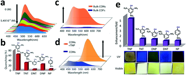 | ||
| Fig. 59 (a) Turn off sensing (PL quenching) and (b) degree of fluorescence quenching of TfpBDH-CONs with different nitro analytes. (c) Photoluminescent spectra of bulk TfpBDH and TfpBDHCONs. (d) Photoluminescent spectra showing turn on (PL enhancement) of bulk TfpBDH-CONs and with TNP. (e) Photoluminescence enhancement plots of different analytes [5.4 × 10⁻³ M] with TfpBDH-CONs. Reproduced with permission from ref. 149, Copyright The Royal Society of Chemistry (2015). | ||
TpBDH-COFs and CONs do not show PL activity due to the restricted π-conjugation arising from enol–keto tautomerism. Conversely, there are no free OH groups present in TfpBDH-COFs and CONs, which limit their tautomerism, and therefore, they exhibit high FL intensity. Various nitroaromatics, such as TNP, TNT, 2-NP, DNT and DNP, were detected using CONs in both solution and dispersed phase showing quite opposite trends. In the solution phase, the FL intensity of TfpCON is quenched by 63% with TNP (detection limit of 5.4 × 10⁻⁵ M), which is attributed to the electronic charge transfer from the π-acidic analyte (the picrate anion) to the rich electron cloud of the protonated nanosheet. On the contrary, ‘turn-on’ sensing behaviour was observed when the weak blue emission of a Tfp-BDH-CON-coated paper strip changed to a bright-yellow color upon the addition of TNP analyte. This was caused by the proton transfer from the phenolic group of the TNP analyte to the basic nitrogen atom of the imine linkage in the solid CONs.
A similar example of a polyimide covalent organic nanosheet was reported by Zhang et al.233 PI-CONs were comparatively more emissive than PI-COFs, which were synthesized via ultrasonic delamination. The nanosheet exhibited high quenching of TNP with 64% FL quenching and limit of detection 0.25 μM. The mechanistic explanation indicates electron transfer between the protonated PI-CONs and TNP−, which was supported by theoretical calculations using DFT functional and the B3LYP basis set, where upon its addition, the inner filter effect (IFE) could be seen. The IFE occurs when there is re-absorption of the emitted light by the quencher. The evident spectral overlap between the absorption spectrum of TNP and the emission spectrum of PI-CONs confirms this quenching phenomenon.
As presented in the previous sections, the controlled and systematic choice of the monomers and reaction conditions leads to a framework with the desired topology and dimensionality. A two-fold interpenetrated 3D-PY-COF emits yellow-green luminescence when dispersed in DMF and excited at λex = 408 nm. The elevated FL intensity of the COF originates from the imine-functionalized pyrene moieties in its framework.46 The titration experiments evidently showed the selective and sensitive detection of TNP (up to 75%) in DMF with a detection limit of 20 ppm. This was the first 3D-COF proven to be a potential candidate for sensing NACs.
Recently, Das et al. also reported a nitrogen-rich dual-functionalized 2D COF, which was formed from triazine-based trialdehyde (tri(4-formylphenoxy)cyanurate) and electron-rich naphthalene diamine monomers.24 A unique six-fold interpenetrated framework was obtained, where the ABC stacked sheets gave rise to a star-like topology. The entangled hexagonal honeycomb sheets reduced the BET surface area (ca. 294 m2 g−1), sculpting a triple-pore framework (ca. 0.75 nm, 1 nm and 2.1 nm) corresponding to micro and mesopores. This multi-faceted COF was utilized for (1) the detection of trace amounts of TNP in water due to the presence of π-electron-rich naphthalene moieties, (2) separation of benzene and cyclohexane using the π-acidic triazine moiety and (3) decoding of volatile organic compounds. Being highly emissive and chemically stable in aqueous media, the COF selectively detected the electron-deficient trinitrophenol up to the lower limit of 68 ppb with a Ksv value 30-times higher than that for the other NACs. Further improvisation was reported for the ultrafast real-time detection of NACs through instant spot via paper strips. A significant color change from blue to green for the FL quenching by TNP was observed, making the COF very handy. This ‘turn-off’ sensing is attributed to the energy transfer from the framework to TNP analyte and photo-induced electron transfer from the LUMO of the COF to the low-lying conduction band of TNP. In addition, the H-bonded interactions between the N- and O-functionalities and –OH group of TNP contributed 90% quenching.
Last year, another luminescent COF (namely ANCOF) was synthesized by Das et al. for the water-based sensing of nitroaromatic explosives and amines such as dichloronitroaniline (DCNA), 4-nitroaniline (4-NA), 2,4-dinitroaniline (DNA), 3-nitroaniline (3-NA), 2-nitroaniline (2-NA), aniline (AN), 4-nitrotoluene (4-NT), ethylene diamine (EDA), triethylamine (TEA), 1,2-diaminobenzene (DAB) and N,N-dimethyl-p-phenylenediamine (DMPD).154 The appended π-electron rich sites in the framework act as recognition sites for the selective detection of dichloran (other name for DCNA) and 4-NA in water/MeOH (Fig. 60). More than 80% quenching with a large bathochromic shift in the FL intensity of ANCOF (ca. 21 nm and 19 nm) and lower limit of detection (ca. 142 ppb and 89 ppb) for DCNA and 4-NA, respectively, was observed. The mechanistic insight showed the presence of resonance energy transfer, photo-induced electron transfer (PET) and distinctive H-bonding interactions between the triazine moiety and Cl atom in DCNA and amine hydrogens in 4-NA. In addition, the lifetime measurements shed light on the static quenching mechanism at lower analyte concentrations, while the dynamic quenching mechanism occurs at higher concentrations. Moreover, the two-fold interpenetration of the framework with the ABAB arrangement yielded a beautiful marigold-like microfloral morphology.
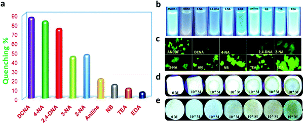 | ||
| Fig. 60 (a) Percentage of fluorescence quenching obtained for different analytes at room temperature. (b) (top to bottom) Response of ANCOF in the presence of various amines by UV illumination, and (c) fluorescence microscopy images: response of ANCOF in the presence of various amine-analytes in the FITC region. Paper strips coated with ANCOF and different concentrations of (d) DCNA and (e) 4-NA. Reproduced with permission from ref. 154, Copyright American Chemical Society (2020). | ||
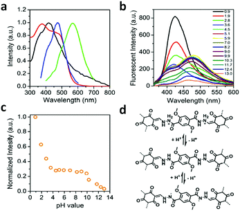 | ||
| Fig. 61 (a) Electronic absorption (in water: black line and in the solid state: red line) and fluorescence spectra (in water: blue line and in the solid state: green line) of COF-JLU4. (b) pH-Dependent fluorescence of COF-JLU4 in aqueous solution with pH ranging from 0.9–13.0 measured under excitation at 334 nm. (c) Photoluminescent intensity of COF-JLU4 at 428 nm in aqueous solutions with different pH values. (d) Deprotonation and protonation processes of the COF-JLU4 framework in acidic and basic media. Reproduced with permission from ref. 144, Copyright The Royal Society of Chemistry (2016). | ||
Another COF reported for colorimetric pH sensing contained a pH-sensitive fluorescent chemical group, 8-hydroxyquinoline (HQ).234 COF-HQ was solvothermally synthesized by Chen et al. from the HQ-substituted terephthaldehyde monomer and TAPB, yielding a quite low surface area and semi-occupied pores. This HQ-functionalized framework possesses good acidic and hydrolytic stability, and thus exhibits high luminescent intensity, which is strongly correlated with the pH of the aqueous medium. Unlike COF-JLU4, the fluorescence intensity of COF-HQ is completely quenched in a highly acidic medium at pH = 1.0 due to the protonation of the 4-hydroxyquinoline group inside the pores. Conversely, when the pH is raised to 5.0, the HQ grafted inside the framework gets deprotonated, leading to a gradual increase in the emission intensity. This has a good linear relationship with the correlation coefficient of R2 = 0.979. COF-HQ acts as a colorimetric-based pH sensor as its color turns black when the luminescence is quenched and intensifies to dark orange under basic conditions at pH ≥ 5.0.
Recently, two porphyrin-based COFs were utilized as colorimetric pH-responsive materials in the pH range of 0 to 7.0. TPE-Por-4 and TPE-Por-2 were distinctively constructed under solvothermal conditions.235 Between them, the highly crystalline TPE-Por-4 displays enhanced luminescence intensity due to (1) aggregation-induced emission (AIE) by the non-planar TPE chromophore, (2) the adequate layer spacing among the AB stacked COF, leading to the restriction of its intramolecular rotation (RIR), which enhances its FL emission, and (3) loose stacking and weak π–π interaction because the twisted TPE prevents FL quenching. Furthermore, colorimetric pH-responsive studies were conducted, showing a bathochromic shift (∼15 nm) and hyperchromic shift of the emission peak from 2.01 to 4.15 nm. This is due to the more protonated N-atoms inside the porphyrin rings at a high hydrogen ion concentration, which destroys the π-electron-conjugated double-bond system, leading to fluorescence quenching. The TPE-Por-4 COF showed an obvious color change from dark red to bright green below pH 2.0, but no marked change above this value was seen.
Working in this direction, Das et al. reported the synthesis of three nitrogen-rich flexible COFs namely CON, CONN, and CONNCO (vide supra, Section 4.2) for sensing different acidic and basic environments.124 These flexible COFs are pH-stable, possess very high BET surface areas (867 m2 g−1) and pore size (4.2 Å for CONNCO), and have imine, amide, and hydrazide linkages, which provide inter and intramolecular H-bonding among their stacked layers. These flexible COFs were utilized as reversible fluorescent ON–OFF pH sensing materials (Fig. 62). For CON, the luminescent intensity increases, and a sharp blue shift (∼50 nm) was observed from pH 1.0 to 13.0. In highly basic conditions, the deprotonation of the N-atom leads to electron transfer towards the π-acidic triazine moiety, and hence a wavelength shift is observed in this region. On the contrary, CONN shows the opposite trend, exhibiting turn ON sensing from basic to acidic medium. This is due to the emergence of extra intramolecular H-bonding in acidic conditions together with the prior intermolecular H-bonding between the carbonyl O and NH groups. Conversely, CONNCO exhibits the highest luminescent intensity at pH 4.0 and shows moderate quenching at high acidic and basic conditions. Under these conditions, the intramolecular H-bonding for CONNCO is destroyed, allowing intramolecular rotation, and the emission is quenched. From pH 7.0 to 4.0, the protonation of the N-atoms in the hydrazide linkage dominate the intramolecular H-bonding, resulting in restriction of intramolecular rotations (RIR). The lifetime studies showed a dynamic process at basic pH for CON and at acidic pH for CONN, whereas at both conditions for CONNCO. The good agreement with the R2 values, i.e., 0.982 and 0.984 in the polynomial fitting, and 0.999 in the linear fit for CON, CONN, and CONNCO, respectively, confirms the good correlation.
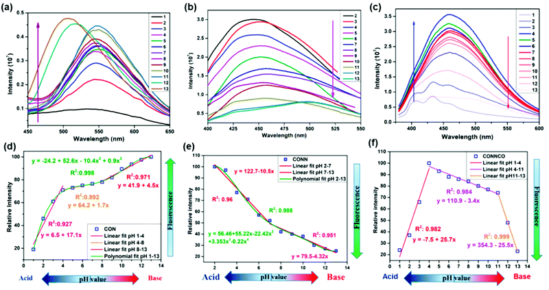 | ||
| Fig. 62 pH-Dependent fluorescence spectra of (a) CON, (b) CONN, and (c) CONNCO in aqueous solution with pH ranging from 1 to 13. Relative fluorescence intensity of (d) CON, (e) CONN and (f) CONNCO at different pH. Reproduced with permission from ref. 124, Copyright the American Chemical Society (2021). | ||
In 2016, Dalapati and co-workers reported the synthesis of TPE-Ph-COF, which is highly emissive due to aggregate-induced emission.29 The COF was synthesized via the solvothermal condensation of tetraphenylethene boronic acid (TPEBA) and 1,2,4,5-tetrahydroxybenzene (THB), developing boronate linkages. This COF was highly crystalline with a BET surface area of 962 m2 g−1, forming a dual-pore kgm net having pore sizes of 1.3 and 2.6 nm. This material was utilized for the detection of ammonia molecules, which showed rapid quenching response in the organic solvents toluene and cyclohexane. It was explained that the Lewis acidic boronate linkages form acid–base interactions with the Lewis basic ammonia molecules, turning off the bright blue luminescence of the COF.
Xie et al. studied and reported the fluorescence properties of the highly crystalline TAT-COF-2.126 This 2D COF was synthesized from the C3-symmetric trialdehyde and triamine derivative of triazatruxene (TAT), forming imine-linkages. The topological [C3 + C3] connectivity weaves the COF with a high BET surface area and pore size of 1166.1 m2 g−1 and 1.48 nm, respectively. Various electron-rich and electron-deficient arenes were successfully sensed using the strong electron-donating abilities of the TAT building unit (Fig. 63). It was found that the FL intensity was enhanced when an ethanolic suspension of TAT-COF-2 was diluted with electron-rich arenes such as toluene, chlorobenzene, o-dichlorobenzene, mesitylene, bromobenzene, 1,2-dimethylbenzene, pyridine, and some solvents such as N-methylpyrrolidone, tetrahydrofuran, ether, triethylamine, dimethylformamide, ethyl acetate, dimethylacetylamide, dimethyl sulfoxide, hexane and chloroform. On the contrary, significant fluorescence turn-off was seen upon dilution with nitrobenzene, 2-nitrotoluene, methanol, water, n-butanol, tetraethylene glycol, dioxane and phenol solution, which are electron-deficient species. Among them, total quenching was achieved upon the addition of 5 drops of nitrobenzene, while ∼60% enhancement was seen with toluene and mesitylene. The phenomenon of electron transfer was responsible for the whole quenching and enhancement of the emission peak.
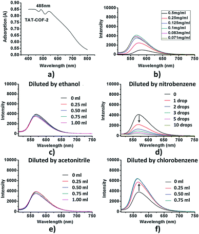 | ||
| Fig. 63 (a) UV-Vis adsorption of TAT-COF-2, (b) fluorescence of TATCOF-2 suspended in ethanol at different densities; 100 mg TAT-COF-2 suspended in 1 mL ethanol and diluted with (c) ethanol, (d) nitrobenzene, with the calculated detection limit of about 10 mM; (e) acetonitrile and (f) chlorobenzene, with the calculated detection limit of about 198 mM. Reproduced with permission from ref. 126, Copyright The Royal Society of Chemistry (2015). | ||
Another truxene-based crystalline COF, Tx-COF-2, was reported recently by Nailwal et al., which was utilized for sensing vapor and solid-phase HCl.240 The framework, being highly stable in 12 M HCl, was exposed to HCl vapor in a 1,4-dioxane suspension. An evident rapid color change from yellow to bright orange was seen, attributing to the protonation of the imine linkages in the framework, showing fast fluorescence enhancement. The detection limit was found to be as low as 4.5 nmol L−1, which is the best reported value for the detection of HCl vapor to date. The reversibility of the framework was noted up to 10 cycles using ammonia vapor with recovery of the framework using triethylamine when the pH is maintained at 7.
N-Rich frameworks with high emissive properties and crystallinity were reported by Mandal and co-workers in 2018.24 A dual-functionalized COF was proven to be potent for sensing various tropospheric VOCs such as benzene, toluene, o-, m-, p-xylene, mesitylene, chloro-, bromo-, iodo-benzene, anisole and cyanobenzene. VOCs have great affinity towards electron-deficient centers, making the COF suitable for VOC sensing. The results showed that the host–guest charge transfer causes the formation of an exciplex, changing the FL intensity and emission wavelength in each case. COF⊃mesitylene showed the maximum emission intensity at 381 nm with a high quantum yield (ca. 0.083) and long average lifetime (ca. 3.89 ns), which was blue-shifted in comparison to other electron-donating VOCs. Conversely, there was a red-shift in the emission wavelength of the COF when benzene was substituted with a heavy atom, viz., iodobenzene, with an increase in its average lifetime. Moreover, the same triazine core was utilized to sense and separate aromatic benzene (Bz) molecules from the non-aromatic cyclohexane (Cy) domain. A red shift in the luminescence intensity of the COF was observed when immersed in benzene with quantum yields of 0.06/0.042 and average lifetimes of 3.47/4.02 ns (Bz/Cy), respectively. This is ascribed to the very strong interactions between the electron-rich Bz and electron-deficient triazine core in the framework.
In recent years, it has been explored that covalent organic frameworks provide a site for hydrogen bond interactions with molecules having carbonyl groups. This led to the sensing of small molecules such as formaldehyde, where the electronegative oxygen atom from the carbonyl group forms hydrogen bonds with the aromatic hydrogens present in the framework. Hao and co-workers investigated the effect of the luminescent properties of the HHTP-DPB COF before and after sensing formaldehyde molecules.237 It was observed that the FL intensity of the HHTP-DPB COF was rapidly quenched after the incremental addition of formaldehyde. Employing the quantum chemical approach, DFT AND TDDFT methods, it was determined that the H-bonding is enhanced in the S1 state, leading to a diminished energy gap between G. S. and E. S. by 0.54 eV after the interaction of formaldehyde and the COF. This was further confirmed by calculation of the H-bond lengths, IR spectra of the donor and acceptor groups and NMR chemical shifts for the framework hydrogens involved in H-bonding in the S0 and S1 states. Also, the FL rate coefficients for the COF and HCHO@COF were 1.22 × 10⁴ and 4.13 × 10³ s−1, respectively, indicating that the FL intensity weakened after the addition of the analyte.
Similar studies were carried out with TT-COF reported by Hussain et al.238 The noncovalent interactions between the thienothiophene-based COF and formaldehyde were investigated using DFT and TDDFT computational tools, which are indicative of strengthened H-bonding and weakened emission intensity after mixing. The FL rate constants for the simulated TT-COF and its complex with HCHO are 1.16 × 10⁸ and 1.45 × 10³ s−1, respectively, strongly indicating the quenching effect. Furthermore, the reduction in band gap between the S1 and T1 states (1.00 to 0.32 eV) indicates the possibility of a radiationless ISC process as the reason for quenching.
Recently, Mandal and co-workers reported two highly crystalline, luminescent and chemically stable COFs, COF-N and COF-NN, decorated with molecular docking sites for solvatochromic decoding of volatile solvent molecules (VSMs).125 The COFs possess pore sizes of 2.7 and 3.06 nm, respectively, with moderate BET surface areas, and thus, the structurally small molecules were deciphered by these materials. On immersing the two COFs in different VSMs with varying polarities such as alcoholic (MeOH, EtOH, 1-PrOH, 2-PrOH, 1-BuOH, 2-BuOH and t-BuOH), chlorinated (DCE, CHCl3, and CH2Cl2) and some aprotic solvents (acetone, acetonitrile, THF, dioxane, EtOAc, DMF, DMA and DMSO), a remarkable color change together with a change in wavelength and emission intensity was noted (Fig. 64). The interactions between the COFs and VSMs were examined using polarity parameters such as Reichardt's, Kamlet–Taft's and Gutmann's parameters. The results showed that the singlet energies are in good luminescence correlation with Reichardt's parameters for COF-N and that with Gutmann's parameters for COF-NN. Moreover, the presence of an extra amine functionality in the COF-NN framework contributed to the electron donation and enhanced the H-bonding interactions with the VSMs.
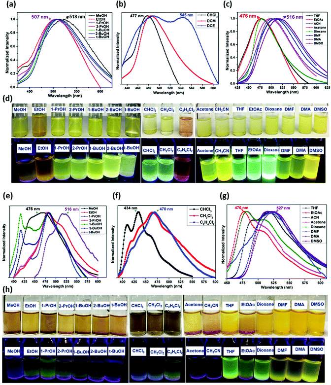 | ||
| Fig. 64 Emission spectra of COF-N and COF-NN in different (a and e) alcoholic, (b and f) chlorinated, and (c and g) aprotic VSMs (0.25 mg in 2 mL). (d and h) Solvatochromic behavior of COF-N and COF-NN in the presence different VSMs (top row: under visible light and bottom row: UV illumination). Reproduced with permission from ref. 125, Copyright the American Chemical Society (2020). | ||
Considering that pyrene-core organic moieties have been widely explored for AIE in covalent organic frameworks, they have also been utilized for turn-on sensing of anionic molecules. An efficient but weakly luminescent N-rich TFPPy-DETHz COF was fabricated through hydrazone bridges and emitted low green-yellow FL intensity due to the ACQ effect (vide Section 6.1.2).137 The luminescent intensity of the COF was enhanced by 3.8-fold that of its original intensity after the addition of a THF solution of tetrabutylammonium fluoride to it. On the contrary, other halogen and nitrate ions did not have any effect on the weakly luminescent framework. This was ascribed to the strong acid–base reaction between the F− ions and N–H units of the hydrazone linkages, which led to deprotonation of these units. However, reversible protonation of N− anions can be successfully carried out by adding triflic acid (TFA) to the system. It must be noted that the TFPPy-DETHz COF was the first report of anion sensing using a porous organic framework.
Common oxidizing agents, such as CrO42−, Cr2O72− and MnO4−, are widely used in laboratories and industry, which pose a threat to the environment and mankind. Therefore, it is essential to monitor and sense these anions using efficient and easy to handle probes, such as porous organic polymers. Li and co-workers developed the 3D stable and luminescent COF-TT, which exhibited high sensitivity towards the detection of CrO42−, Cr2O72− and MnO4− ions via a turn-off sensing phenomenon (Fig. 65a).242 The COF-TT framework contains a flexible core synthesized from bis(tetraoxacalix[2]arene[2]triazine) and the rigid tetra(paminophenyl)methane. When anions interact with the framework in aqueous medium, a strong competitive energy transfer process occurs, which was validated by UV-Vis spectroscopy. The spectral overlap of the adsorption band of COF-TT with the wide range absorption bands of the three anions supports the quenching mechanism. With up to 0.8 mM (for CrO42− and Cr2O72−) and 0.7 mM (for MnO4−) anionic concentration, the framework completely lost its luminescent property. This makes COF-TT an excellent anion sensor with a detection limit of 3.43 × 10⁻⁴ M (for CrO42− and Cr2O72−) and 3.20 × 10⁻⁴ M (for MnO4−).
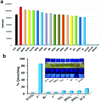 | ||
| Fig. 65 (a) Fluorescence intensities of COF-TT for different anions. (b) % quenching of DATGCl-iCONs upon the addition of different anions. Reproduced with permission from: (a) ref. 242, Copyright The Royal Society of Chemistry (2019) and (b) ref. 114, Copyright the American Chemical Society (2020). | ||
Another strategy for anion sensing is by incorporating an ionic linker as a monomeric unit to synthesize ionic frameworks. Recently, triguanidinium chloride (TGCl) was utilized as an anion acceptor linker, which was combined with a fluorescent-active dimethoxyterephthaldehyde (Da) unit to give ionic covalent organic nanosheets, namely DATGCl-iCONs, via self-exfoliation in methanol (Fig. 65b).114 The addition of F− to the cationic sensor caused great fluorescence quenching with a detection limit of 5 ppb level. A unique property of the guanidinium linker is its ability to donate a proton (in the presence of F− ions) and abstract it again (by adding HCl). The appropriate basic nature of the F− ions in the framework environment leads to the abstraction of a proton, which gives rise to turn-off sensing. Moreover, the further addition of HCl supplies enough H+ to bind the guanidinium unit and regain its fluorescent property. According to the theoretical studies, it was found that the quenched luminescence of DATGCl-iCONs occurs via the photo-induced electron transfer mechanism, which was supported by time-resolved fluorescence spectroscopy, showing dynamic quenching. The turn-off/on sensing was repeated successfully for up to five cycles with minimum loss of the sensor.
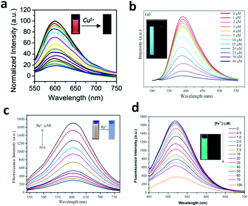 | ||
| Fig. 66 (a) Luminescence spectra of COF-JLU3 in THF suspension containing different concentrations of Cu2+ (0 to 2 × 10⁻⁴ M), λex = 400 nm. The inset shows the corresponding images of COF-JLU3 under UV irradiation at 365 nm before and after titration with Cu2+ ions. (b) Fluorescence emission spectra of CTFQD in aqueous solution at different concentrations of Hg2+. (c) Fluorescence titration of AH-COF in the acetonitrile upon treatment with Hg2+. (d) Fluorescence emission spectra of Bth-Dma COF at various concentrations of Fe3+ ions. Reproduced with permission from: (a) ref. 245, Copyright The Royal Society of Chemistry (2016); (b) ref. 250, Copyright The Royal Society of Chemistry (2017); (c) ref. 251, Copyright Elsevier (2020) and (d) ref. 141, Copyright the American Chemical Society (2019). | ||
Other COFs for the efficient sensing of Cu2+ ions are Q-graphene (QG)-grafted COF,246 which detects up to 0.5 nM, and nitrogen-rich CTF247 with a detection limit of 0.05 μgL−1.
Bipyridine-based COF nanosheets (Tp-Bpy NSs) exhibit a structure with regular pores and abundant N-based moieties, which act as active sites for the detection of Hg2+ ions.248 The Tp-Bpy nanosheets were prepared via ultrasonic exfoliation, on which Au nanoparticles were loaded to form the AuNPs@Tp-Bpy nanocomposite. The affinity between gold and mercury suggests the high selectivity of AuNPs@Tp-Bpy towards Hg2+ ions with a detection limit of 0.33 nM. The framework was enriched with nitrogen, which provides ultra-affinity for Au nanoparticles, and therefore, it provides an excellent platform to detect Hg2+ with good selectivity and sensitivity in real-life sensing applications.
In addition, COF-LZU8 was also utilized for sensing Hg2+ with a very low detection limit of 25.0 ppb.249 Recently, COFs have been explored to make quantum dots, which exhibit high luminescent properties for metal ion analyte sensing. The CTF-based N-doped quantum dots (CTFQDs) detected Hg2+ ions up to a limit of 0.23 μM (Fig. 66b).250
The highly fluorescent AH-COF, which was synthesized using hydroxyl functionalized 2,5-diallyl-3,6-dihydroxyterephthalohydrazide and 1,3,5-benzenetricarboxaldehyde, was utilized for selective and rapid Hg2+ ion sensing (Fig. 66c).251 This COF possesses exceptional luminescent properties due to its excited-state intramolecular proton transfer (ESIPT) and increased π-conjugation. According to the simulated PXRD showing its eclipsed packed structure, one unit cell exhibits six reacting receptor sites, which consist of allyl and hydroxyl groups. The Hg2+ ions firstly bind to the hydroxyl groups, forming an Hg-containing five-membered ring, blocking the ESIPT mechanism from occurring, which finally quenches the FL intensity of the framework.
For the detection of toxic lead ions in aqueous media, a novel electrochemical sensor, named TAPB-DMTP-COF, was utilized.252 This COF was formed via the imine condensation of 1,3,5-tris(4-aminophenyl)benzene (TAPB) and 2,5-dimethoxy terephthaldehyde (DMTP). Lead ions were attached to the surface of TAPBDMTP-COF via the formation of a complex with its amine moiety. This sensor exhibited a broad linear range, ultra-stability, low detection limit and great sensitivity towards Pb2+ ions due to its large active sites and surface area. The wide surface area of these electrochemical sensors will provide an excellent platform in environmental monitoring and clinical diagnostic applications.
A series of imine-linked COFs, namely TaTa, DhaTab, TRITER-1 and TzDa, was utilized for the detection of Fe3+ ions in DMF/H2O (9![[thin space (1/6-em)]](https://www.rsc.org/images/entities/char_2009.gif) :
:![[thin space (1/6-em)]](https://www.rsc.org/images/entities/char_2009.gif) 1, v/v) medium. The luminescent-active N-rich frameworks underwent strong PL quenching due to the absorption competition quenching effect of Fe3+ ions, with the highest quenching coefficient for DhaTab (1.0 × 10⁵ M−1, LOD = 0.12 μM) followed by TaTa (1.4 × 10⁴ M−1), TRITER-1 (5.6 × 10³ M−1) and TzDa (3.3 × 10³ M−1). Moreover, a slight increase in the luminescent intensity of all four COF sensors was observed due to their strong interactions with Al3+ ions.253 In the following year, a new hydrazone-linked Bth-Dma COF was employed as a sensor to detect Fe3+ ions via the selective coordination of these ions with the O,N,O′-chelating sites on the pores of the framework (vide supra, Section 4.2).141 Switch-off quenching was reported with an LoD value of 0.17 μM. Additionally, neither the presence of anions (Cl−, Br−, NO3− and OAc−) nor change in pH from 4 to 10 caused a change in the quenching profile of the COF (Fig. 66d). To support the electron and energy transfer quenching mechanism, XPS was used, which showed a decrease in the binding energy values for Bth-Dma and Bth-Dma@Fe3+ (see Section 5.5). Later, Asadi et al. synthesised benzimidazole-linked COFs, viz. COF-BI-1 and COF-BI-2, which were conventionally synthesized using pyromellitic dianhydride (PMDA)/Perlin-tetracarboxylic anhydride (PTCA), 5-aminoisophthalic acid and 3,3′-diaminobenzidine, showing significant fluorescent quenching with the incremental addition of an Fe3+ ion solution to COF-BI-1 in THF and COF-BI-2 in DMF up to a limit of 1.3 μM.254
1, v/v) medium. The luminescent-active N-rich frameworks underwent strong PL quenching due to the absorption competition quenching effect of Fe3+ ions, with the highest quenching coefficient for DhaTab (1.0 × 10⁵ M−1, LOD = 0.12 μM) followed by TaTa (1.4 × 10⁴ M−1), TRITER-1 (5.6 × 10³ M−1) and TzDa (3.3 × 10³ M−1). Moreover, a slight increase in the luminescent intensity of all four COF sensors was observed due to their strong interactions with Al3+ ions.253 In the following year, a new hydrazone-linked Bth-Dma COF was employed as a sensor to detect Fe3+ ions via the selective coordination of these ions with the O,N,O′-chelating sites on the pores of the framework (vide supra, Section 4.2).141 Switch-off quenching was reported with an LoD value of 0.17 μM. Additionally, neither the presence of anions (Cl−, Br−, NO3− and OAc−) nor change in pH from 4 to 10 caused a change in the quenching profile of the COF (Fig. 66d). To support the electron and energy transfer quenching mechanism, XPS was used, which showed a decrease in the binding energy values for Bth-Dma and Bth-Dma@Fe3+ (see Section 5.5). Later, Asadi et al. synthesised benzimidazole-linked COFs, viz. COF-BI-1 and COF-BI-2, which were conventionally synthesized using pyromellitic dianhydride (PMDA)/Perlin-tetracarboxylic anhydride (PTCA), 5-aminoisophthalic acid and 3,3′-diaminobenzidine, showing significant fluorescent quenching with the incremental addition of an Fe3+ ion solution to COF-BI-1 in THF and COF-BI-2 in DMF up to a limit of 1.3 μM.254
An evident fluorescence “turn-on” mechanism was reported by Qiu and co-workers, where the PL intensity of the water-stable covalent organic nanosheets Bpy-NSs was enhanced with the incremental addition of Al3+ ions among several monovalent (Li+, Na+, K+, and Ag+), divalent (Zn2+, Mn2+, Cd2+, Cu2+, Mn2+, Ni2+, Co2+, Pb2+, Ba2+, and Ca2+) and trivalent (Cr3+ and Fe3+) metal ions in aqueous media.255 The photoluminescence intensity of the N-rich Bpy-NSs nanosheets was limited due to extensive energy dissipation by their bipyridine (Bpy) moieties, leading to photoinduced electron transfer to the phloroglucinol centres. However, the addition of Al3+ ions resulted in the formation of a strong Lewis acid–base coordination complex with the Bpy-core, in which the electrons occupy the lowest energy orbital, preventing the PET process. The detection limit for Al3+ ions was as low as 0.33 μM.
The olefin-linked TFPT-BTAN-AO COF was formed via Knoevenagel condensation followed by post-synthetic modification through amidoximation by treating it with excess NH2OH·HCl at 85 °C for 24 h.256 This made the framework rich in –OH and –NH2 functional groups and the material was utilized to detect uranium ions in aqueous medium. The UO22+ units reversibly bind to the N and O atoms of the amino and the hydroxyl groups, respectively, and the COF detects uranium ions up to 6.7 nM with an ultra-fast response time of 2 s. The UO22+@TFPT-BTAN-AO COF could be regenerated when dispersed in 1 M Na2CO3 aqueous solution as it has >95% elution efficiency for up to 6 cycles.
In 2017, Li et al. reported a biosensor, named TpTta-COF, which was solvothermally synthesized using 4,4′,4′′-(1,3,5-triazine-2,4,6-triyl)trianiline (Tta) and 1,3,5-triformylphloroglucinol (Tp) units.257 Initially, the COF was tagged with an FAM-labeled probe, which was adsorbed on its surface and inside its pores via H-bonding and π–π stacking interactions (Fig. 67). The carboxyfluorescein in the FAM probe shows very strong luminescence, which was quenched upon contact with COF (acceptor) via fluorescence resonance energy transfer (FRET). The probe (5′-FAM-TCG CTA ACC TGT TCA TCG TAG-3′) was uniquely designed to be complementary to the target DNA analyte (5′-CTA CGA TGA ACA GGT TAG CGA-3′). After the DNA analyte comes in contact with the COF quenched FAM-labeled probe, the formation of double-stranded DNA occurs, resulting in complete detachment of the probe from the framework. The rapid formation and detachment process resulted in the turn-on sensing of DNA with the limit of 3.7 nM.
 | ||
| Fig. 67 Turn-on fluorescent sensor for the detection of biomolecules. Reproduced with permission from ref. 257, Copyright The Royal Society of Chemistry (2017). | ||
Peng et al. reported the synthesis of imine-based covalent organic nanosheets (NS), TPA-COF NSs, via the chemical exfoliation of TPA-COF, which was previously synthesized using tris(4-formylphenyl)amine (TFPA) and tris(4-aminophenyl)amine (TAPA) under solvothermal conditions.107 The ultrathin NSs were well exploited for the highly selective and sensitive ‘switch-on’ sensing of DMA molecules, which mechanistically takes place exactly like the previous example in Fig. 67. Initially, two types of hairpin-like DNA probes, denoted as H1 and H2, were fabricated, one of which was FL tagged, and then allowed to adsorb on the TPA-COF nanosheets via π–π stacking (Fig. 68). This led to fluorescence quenching, which was again revived by the hybridization chain reaction (HCR) between the two probes on the surface of the NSs. A long double-stranded DNA (dsDNA) was formed and detached from the NSs due to the weaker p–p interactions. Furthermore, the fluorescence intensity was enhanced by increasing the concentration of the targeted DNA up to 1 nM and a good linear relation was achieved. The LoD value for DNA in this case was found to be very low, i.e., 20 pM.
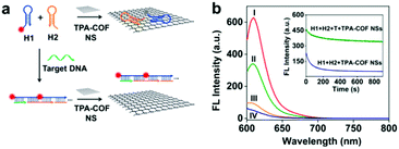 | ||
| Fig. 68 (a) Schematic representation of a TPA-COF NS-based fluorescence sensor to detect DNA. (b) Fluorescence spectra recorded with different conditions: (I) H1 + H2; (II) H1 + H2 + T + TPA-COF NSs; (III) H1 + T + TPA-COF NSs; and (IV) H1 + H2 + TPA-COF NSs. Reproduced with permission from ref. 107, Copyright the American Chemical Society (2017). | ||
Myocardial infarction is a life-threatening cardiovascular disease, which can be prevented by the early detection of the biomarker cardiac troponin I (cTnI). In this direction, Zhang et al. reported an electrochemical immunosensor decorated with gold nanoparticles, TiO2-PPy (TiO2-PPy-Au).258 This material was efficiently employed to detect cTnI quantitatively through the signal amplification strategy (Fig. 69). Initially, TiO2-PPy-Au was decorated with primary antibodies (AB1) on a GCE electrode. Conversely, the Au NP-decorated COF was subjected to secondary antibodies (AB2) and toluidine blue (TB) aromatic dye via its amino-groups. The two units then behave as a sandwich-type electrochemical sensor for cTnI analyte. The proposed technique displayed a linear range from 0.5 pg mL−1 to 10.0 ng mL−1 together with a low detection limit of 0.17 pg mL−1.
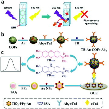 | ||
| Fig. 69 (a) Process for the detection of antibiotics with COF-1. (b) Procedure for the preparation of the TB-Au-COFs-Ab2 labels. (c) Schematic illustration of the sandwich-type electrochemical immunosensor. Reproduced with permission from: (a) ref. 262. Copyright the American Chemical Society (2020) and (b) ref. 258. Copyright Elsevier (2018). | ||
In 2018, Wang et al. synthesized a porphyrin-based Fe-COF, which was utilized as a peroxidise mimic.259 The COF undergoes colorimetric sensing of H2O2 and glucose molecules up to very low detection limit of 1.1 and 1.0 μM, respectively. The mechanism of the biosensing experiment involved the oxidation of the chromogenic substrate TMB in the presence of H2O2, where the peroxidise-mimetic Fe-porphyrin-COF captures OH radicals upon its decomposition. This was supported by observing the color change from colorless (for TMB) to blue (for oxTMB). After this, the framework was utilized for the detection of glucose. By combining the COF with glucose oxidase (GOx), the glucose molecules were oxidized to gluconic acid with high sensitivity and selectivity.
Recently, COFs have been utilized to detect H2S gas in living cells, tumor tissues, etc. to diagnose neurodegenerative diseases. The COF TpASH was formed via the Schiff-base condensation of 1,3,5-triformylphloroglucinol (Tp) and the PTSA salt of 4- aminosalicylhydrazide (ASH), which was then tagged with a fluorescent probe via post-synthetic modification.111 The phenolic groups in TpASH were first alkylated by glycidol (Glc) on which a 4-amino-1,8-naphthalimide derivative (NPHS) was anchored. This functionalized TpASH-NPHS framework was then exfoliated chemically to yield active nanosheets for the detection of H2S.260 In the presence of H2S, the azide units present on the NPHS-modified nanoprobe were reduced to amino group, causing an enhancement in the fluorescent emission with a detection limit of 0.11 μM. In addition, the TpASH-NPHS fluorescent nanoprobe was employed to detect and image the H2S in deep tumor tissues, HeLa and HepG2, and in a cirrhotic liver.
Furthermore, chiral COFs (CCOFs) have been proven to be promising candidates for the enantioselective recognition of chiral molecules due to the presence of chiral-functionalized crown ether units in their framework.261 Crown ethers contain free electron pairs, and thus have the ability to form complexes with ammonium ions, binding them through H-bonds. The formation of an adduct between the immobilized crown ether and protonated amines increases the interlayer spacing among the CCOF layers by weakening the π–π interactions among them. This causes a change in fluorescent intensity.
In terms of food safety, the detection of antibiotics is necessary and provides insight in various food detection fields. Recently, attempts have been made in this direction. The green synthesis of a polyimide COF, named COF-1, was reported, showing very high luminescence at 530 nm (λex = 369 nm) in DMF, which is attributed to its perylene core and triazine monomeric units. Significant FL quenching was observed in the presence of the antibiotics ofloxacin and tetracycline, with a detection limit of 0.002 and 0.0065 mM, respectively, as shown in Fig. 69a.262
It is well known that antibiotics consist of various aromatic units, particularly, benzene ring units. Examples of these antibiotics are ampicillin (AMP) and enrofloxacin (ENR), which were effectively sensed by the novel pyrene-core Py-M-COF.263 This COF was constructed using melamine and TFPPy units, possessing a nanosheet-like structure, which is rich in functional groups such as amino, keto, imino and olefin groups. This enabled the framework to act as a good charge carrying probe. Moreover, the very high FL intensity of this framework is attributed to the presence of Py cores and extended π-conjugation. The COF behaves as an electrochemical aptasensor as it was first anchored with aptamers via π–π stacking and electrostatic interactions. The ENR aptamers sense ENR molecules, and the AMP aptamers detect ANP molecules. There was an observable change in the confirmation and flexibility of the aptamer during the detection of AMP, whereas the ENR aptamer folded upon binding ENR. Extremely low detection limits for both antibiotics were calculated, i.e., 6.07 and 0.04 fg mL−1 (S/N = 3) for ENR and AMP, respectively.
Voort and co-workers attempted the synthesis of the first TpBpy-COF grafted with various lanthanides (Ln3+ = Eu3+, Tb3+, Eu3+-Tb3+, and Dy3+) to serve as a heat detecting material in different temperature ranges.264 Initially, the TpBpy COF was synthesized solvothermally from triformylfluoroglucinol (Tp) and 2,2′-bipyridine-5,5′-diamine (Bpy), which was then implanted with different Ln3+ ions using Ln(acac)3(H2O)2 and LnCl3. Among them, Eu, the Eu/Tb- and Dy-grafted systems were successfully employed as ratiometric thermometers in the temperature range of 10–360 K for the former two and 280–440 K for the latter (Fig. 70). In the Eu3+-sensitized TpBpy-COF (labelled 1), the sharp FL peak corresponding to 610 nm (λmax) with respect to the 5D0 →7F2 transition gradually decreased with an increase in temperature, whereas no significant change was found for the Tb3+-grafted COF (labelled 2), corresponding to the 5D4 → 7F5 transition at the emission maximum of 548 nm. This is ascribed by the absence of Tb3+-to-ligand back energy transfer due to the fact that the 5D4-acceptor band lies above the donor triplet level of the TpBpy ligand, which is present for the former case. In the mixed ion-grafted COF (labelled 5) with an Eu3+: Tb3+ ratio of 80![[thin space (1/6-em)]](https://www.rsc.org/images/entities/char_2009.gif) :
:![[thin space (1/6-em)]](https://www.rsc.org/images/entities/char_2009.gif) 20, a similar trend was observed given that the Tb3+-to- Eu3+ energy transfer is not possible due to the long distance between the ions. Therefore, Tb3+ did not show any quenching effect with an increase in temperature. A visible color change from orange-red to green for 5 was observed when the temperature was increased from 60 K to 360 K. The results are highly convincing, with a thermal sensitivity of 1.403% K−1 (160 K) and error bar of ∼1 K above 110 K. Moreover, the Dy3+ hybrid TpBpy COF also showed strong luminescence (482 nm, 4F9/2 → 6H15/2 transition), which was gradually quenched with an increase in temperature from 280–440 K.
20, a similar trend was observed given that the Tb3+-to- Eu3+ energy transfer is not possible due to the long distance between the ions. Therefore, Tb3+ did not show any quenching effect with an increase in temperature. A visible color change from orange-red to green for 5 was observed when the temperature was increased from 60 K to 360 K. The results are highly convincing, with a thermal sensitivity of 1.403% K−1 (160 K) and error bar of ∼1 K above 110 K. Moreover, the Dy3+ hybrid TpBpy COF also showed strong luminescence (482 nm, 4F9/2 → 6H15/2 transition), which was gradually quenched with an increase in temperature from 280–440 K.
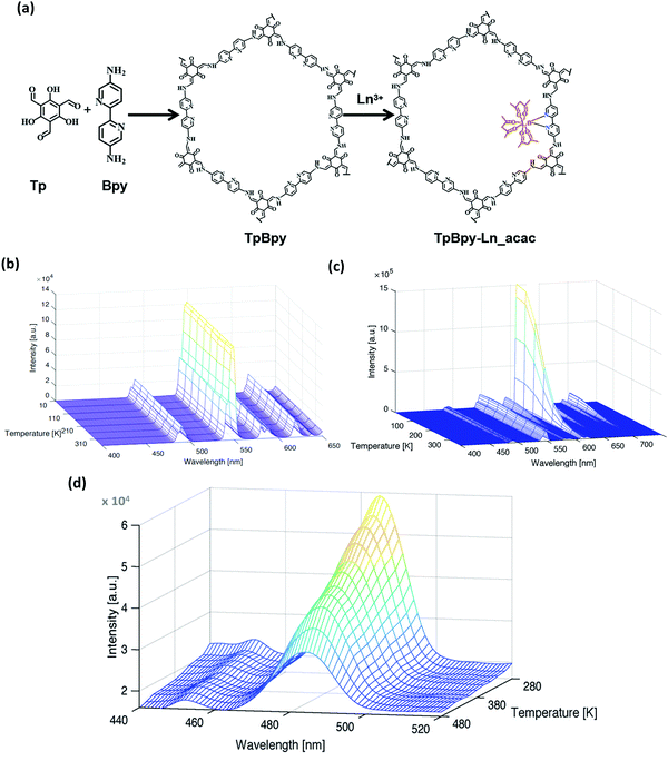 | ||
Fig. 70 (a) Schematic representation of TpBpy and TpBpy-Ln_acac COF materials. Emission map of (b) Tb3+-grafted and (c) Eu3+: Tb3+ (80![[thin space (1/6-em)]](https://www.rsc.org/images/entities/char_2009.gif) : :![[thin space (1/6-em)]](https://www.rsc.org/images/entities/char_2009.gif) 20)-grafted TpBy COF recorded at 10–360 K and (d) Dy3+-grafted TpBy COF at 280–480 K. Reproduced with permission from ref. 264, Copyright John Wiley and Sons (2020). 20)-grafted TpBy COF recorded at 10–360 K and (d) Dy3+-grafted TpBy COF at 280–480 K. Reproduced with permission from ref. 264, Copyright John Wiley and Sons (2020). | ||
In 2020, another PP-TzDa COF was synthesized, which senses thermal changes in its environment without using Ln3+ ions.265 The PP-TzDa COF was obtained by mixing tri(4-aminophenyl)triazine and 2,5-dihydroxyterephthaldehyde as monomers, followed by post-synthetic modification with the chloro-derivative of 2-phenylpropionic acid. The highly emissive COF exhibits luminescence due to (a) extended π-conjugation and (b) ESIPT causing dual-emission (530 and 597 nm) due to the presence of –OH groups, which further react during PSM. The emission maximum at 597 nm is sharply quenched in the temperature range of 20–100 °C in DMF with a δT higher than 0.1 °C and maximum temperature sensitivity of 0.95% per °C (Fig. 71).
 | ||
| Fig. 71 (left) Synthetic route to PP-TzDa. (right) Fluorescence emission spectra of PP-TzDa in DMF (λex = 460 nm nm) at 20–100 °C. Reproduced with permission from ref. 265, Copyright Elsevier (2020). | ||
According to the above-mentioned experiments, Ln3+-COF hybrids have been proven to be a new and emerging class of porous materials that can be exploited as luminescent thermometers. This year, another 4f-3d-grafted COF was reported, in which the TTA-DFP COF was grafted with Eu3+, Tb3+, Cu2+ and Ni2+ ions.266 Subsequently, this COF was subjected to Eu(tfac)3·2H2O or Tb(tfac)3·2H2O and Cu(OAc)2 one at a time, forming the Eu,Tb@TTA-DFPCOF@Cu material. It was further used for dual-ion thermometry application in the temperature range of 0–120 °C and 20–90 °C in toluene medium before and after co-grafting with Cu2+ ions, respectively. Interestingly, it was found that the Eu,Tb@TTA-DFP COF, before Cu2+-grafting, undergoes emission quenching with thermal sensitivity of 4.1% °C at 42 °C. Conversely, with the Cu-grafted Eu,Tb@TTA-DFP COF, there was an increase in emission intensity and good thermal uncertainty of δT < 0.37 °C in the range of 20–90 °C was observed. Being embedded with Cu2+/Ln3+ ions, this material was synchronously used as a thermometer and catalyst for the Glaser reaction.
7. Concluding remarks and future perspectives
In this review, we described the growth of COFs, starting from 2005 to date, to illustrate how this field has grown tremendously and attracted the attention of scientists at the global level. Recapitulating the main points, we briefly explained how the choice of monomer, oriented at a particular angle with an appropriate geometry, tailors various networks with a number of topologies. Consequently, this affects various properties of the framework such as formation of highly ordered structures, its stability towards heat, chemical exposure and moisture, surface areas and pore size. The tremendous efforts in establishing various linkages to build the featured COF were explained in this review. The classification of COFs in 2D and 3D nets was thoroughly explained in the different sections. Additionally, the effect of stacking forces on the construction of 2D COFs and the property of interpenetration in 3D COFs were elaborated with various examples. We also described the various synthetic methodologies such as room temperature, hydro-/solvothermal, microwave, ionothermal, mechanochemical, interfacial and exfoliation methods adopted for these materials. Various analytical methods including FTIR, SS NMR, PXRD, SEM/TEM, XPS, BET and TGA have been efficiently exploited to characterize and monitor the formation of the framework. The structure modeling of most COFs is done with the help of PXRD data, which helps in predicting and establishing the application of these materials. Incorporating N-rich linkages has promoted these frameworks to act as materials for the sensing of explosives, volatile organic compounds, metal ions, toxic anions, bioanalytes, temperature, pH and many more with high sensitivity and selectivity. The detection of these analytes follows several mechanisms, such as ESIPT, AIE/ACQ, PET, ICT and FRET, which were discussed in detail.Nevertheless, there is a lot to be explored for COFs. Specifically, the three major areas further described below can provide tremendous scope for future research.
(a) Framework construction
There are many 2D and 3D frameworks reported thus far from the simplest and commonly found networks (hcb and dia) to the rarely obtained topologies (tth and bcu). Consideirng that the majority of COFs in the literature chose the [C3 + C2] or [C3 + C3] combined hcb net and [C4 + C2] or [C4 + C4] combined dia net, it is necessary to explore high connectivity for both 2D and 3D COFs, respectively. As a new theme, exploring discrete molecular cages as building units can provide an interesting perspective to inflate the growth of porous networks.(b) New strategies for synthesis
Since the solvothermal approach for the formation of first COF was carried out in 2005, this synthetic method has been largely exploited to tailor the desired framework. However, method uses harsh temperature and vacuum conditions together with the choice of non-green solvents to direct the COF reaction at the laboratory scale. Furthermore, strategic planning and vision are required to understand the formation and growth of suitable single crystals. Therefore, the following aspects need special attention:(i) There is a dire need for the large-scale synthesis of robust frameworks using greener solvents. It must be noted that the high-scale production requires ambient reaction conditions.
(ii) The mechanistic work to establish a road map has been well done for 2D COFs forming boroxine and imine linkages with a few examples explaining the supramolecular interactions between the sheets. However, a more optimized and general method is needed for their synthesis. Henceforth, similar studies should be carried out for other widely explored linkages for a better understanding of the formation of COFs.
(iii) There are only a few single crystal structures known for 3D COF materials to date. Getting insight into the structure and establishing a structure–property relationship will open many other applications for these materials. Therefore, more efforts are needed to grow single crystals of these materials.
(iv) Finally, the post-synthetic modification of COFs is still a challenge with only a few examples known. This area can be explored further to increase the performance of COFs.
(c) Sensing aspect
Compared to other porous and highly stable materials for sensing applications, COFs are less explored for a number of reasons, as stated below. Therefore, finding proper solutions to these issues will definitely bring extraordinary results for showing the usefulness of one of the best porous materials to date.(i) It has been observed that N-rich COF nanosheets are more efficient towards sensing applications in comparison to bulk powders. However, very few CONs have been reported, which use limited synthetic methods. This area has a lot of scope in the formation of well-dispersed nanosheets for several real-time sensing applications.
(ii) Most COFs/CONs are studied for their chemical and thermal stability with a few examples of moisture stability. However, to utilize these materials for real-life applications, their stability towards moisture is of utmost importance. Thus, the design strategies have to be improved to generate materials with this property. For sensing applications, most of the experiments are done using organic solvents. However, for real-life applications, the functioning of sensors in water must be considered.
(iv) The regeneration and reusability of a sensor are always desirable. Thus, to maximize the efficiency of COFs as sensory materials, their regeneration and reusability should also be investigated.
(v) The utilization of COFs for temperature, pH, anion and biomolecule sensing is underexplored. Furthermore, biocompatibility of COFs still needs to be determined for their use in the sensing of bioanalytes.
Abbreviations
| ABN | 4-Aminobenzonitrile |
| ACN | Acetonitrile |
| APPO | 3-Anilino-1-phenyl-2-propen-1-one |
| BATH | 2,5-Bis(allyloxy)terephthalohydrazide |
| BDA | Benzene-1,4-diamine |
| BDB | 1,1′-Bis(2,4-dinitrophenyl)-[4,4′-bipyridine]-1,1′-diium dichloride |
| BDBA | 1,4-Benzenediboronic acid |
| BET | Brunauer–Emmett–Teller |
| BFBZ | 4,7-Bis(4-formylbenzyl)-1H-benzimidazole |
| BPDA | 4,4′-Biphenyldicarbaldehyde |
| BPDAN | 2,2′-(Biphenyl-4,4′-diyl)diacetonitrile |
| BTCA | 1,3,5-Benzenetricarboxaldehyde |
| BTCH | Benzene-1,3,5-tricarbohydrazide |
| BTTPA | 5,5′,5′′-(Benzene-1,3,5-triyl)tripicolinaldehyde |
| CC | Cyanuric chloride |
| CHDA | trans-1,4-Cyclohexyldiamine |
| DAB | 3,3′-Diaminobenzidine |
| DABD | 2,5-Diamino-1,4-benzenediol dihydrochloride |
| DAHQ-2HCl | 2,5-Diaminohydroquinone dihydrochloride |
| DBU | 1,8-Diazabicyclo[5.4.0]undec-7-ene |
| DCTMP | 3,5-Dicyano-2,4,6-trimethylpyridine |
| DCTSP | 3,5-Dicyano-2,4,6-tristyrylpyridine |
| DETHz | 2,5-Diethoxyterephthalohydrazide |
| DFPBA | 3,5-Diformylphenylboronic acid |
| Dha | 2,5-Dihydroxyterephthalaldehyde |
| DHTA | 2,4-Dihydroxybenzene-1,3,5-tricarbaldehyde |
| 2,3-DHTH | 2,3-Dihydroxyterephthalohydrazide |
| 2,5-DHTH | 2,5-Dihydroxyterephthalohydrazide |
| DMA | Dimethyl acetamide |
| Dma | 2,5-Dimethoxyterephthalaldehyde |
| DMB | 2,5-Dimethyl-1,4-benzenediamine |
| DMOB | 3,3′-Dimethoxybenzidine |
| DMPO | 5,5-Dimethyl-1-pyrroline N-oxide |
| DMTH | 2,5-Dimethoxyterephthalohydrazide |
| DMTHA | 9,10-Dimethyl-2,3,6,7-tetrahydroxyanthracene |
| DNB | 3,3′-Dinitrobenzidine |
| DNP | 2,4-Dinitrophenol |
| DPBF | 1,3-Diphenylisobenzofuran |
| DPBP | Di(pyridin-2-yl) [1,1′-biphenyl]-4,4′-dicarboxylate |
| DPPO | 3-(Dimethylamino)-1-phenyl-2-propen-1-one |
| DPT | Di(pyridin-2-yl) terephthalate |
| DPTH | 2,5-Bis(prop-2-yn-1-yloxy)terephthalohydrazide |
| Et3N | Triethylamine |
| FPBA | 4-Formylphenylboronic acid |
| FTIR | Fourier Transform Infrared Spectroscopy |
| HHTP | 2,3,6,7,10,11-Hexadydroxytriphenylene |
| HOPG | Highly oriented pyrolytic graphite |
| HTA | 2-Hydroxybenzene-1,3,5-tricarbaldehyde |
| iPrTAPB | 1,3,5-Tris(4′-amino-3′,5′-isopropylphenyl)benzene |
| MOP | Microporous organic polymers |
| MTAB | 4,4′,4′′,4′′′-Methanetetrayltetrabenzoic acid |
| NMP | N-Methyl-2-pyrrolidinone |
| NP | 2-Nitrophenol |
| NT | 2-Nitrotoluene |
| ODH | Oxalyldihydrazide |
| OHPM | 2,3,9,10,16,17,23,24-Octahydroxyphthalocyaninato metal |
| PATCnC | Polyamide(4,4′,4′′,4′′′-tetra(carboxyphenyl)methane-net-trans-1,4-cyclohexanediamine) |
| PDA | Phenylenediamine |
| PDAN | 2,2′-(1,4-Phenylene)diacetonitrile |
| PMDA | Pyromelliticdianhydride |
| PMMA | Polymethylmethacrylate |
| PT | tert-Butyl pyrene-tetraone |
| PTFE | Polytetrafluoroethylene |
| PXRD | Powder X-ray diffractometry |
| SEM | Scanning electron microscopy |
| TAA | 1,3,5,7-Tetraaminoadamantane |
| TAB | 1,2,4,5-Tetraminobenzene |
| TABPB | 1,3,5-Tris[4-amino(1,1-biphenyl-4-yl)]benzene |
| TA | Terephthaldehyde |
| TAP | 5,10,15,20-Tetrakis(4-aminophenyl)porphyrin |
| TAPA | Tris(4-aminophenyl)amine |
| TAPB | 1,3,5-Tris(4′-aminophenyl)benzene |
| TAPM | Tetra(4-aminophenyl)methane |
| TAPT | 1,3,5-Tris(4-aminophenyl)triazine |
| TATP | Triacetonetriperoxide |
| TATTA | 4,4′,4′′-(1,3,5-Triazine-2,4,6-triyl)tribenzaldehyde |
| TCB | 1,3,5-Tricyanobenzene |
| TCTAB | 1,3,5-Tricarboxylicacid-tris(4-amino-phenyl-amide)benzene |
| TDOEB | 1,3,5-Tris(3-dimethylamino-1-oxoprop-2-en-yl)benzene |
| TEM | Transmission electron microscopy |
| TFB | 1,3,5-Triformylbenzene |
| TFFPB | 1,3,5-Tris(3-fluoro-4-formyl phenyl)benzene |
| TFM | Tetrakis(4-formylphenyl)methane |
| TFMS | Trifluoromethanesulfonic acid |
| TFP | 1,3,5-Triformylphluroglucinol |
| Tfpa | Tris(4-formylphenyl)amine |
| TFPB | 1,3,5-Tris(4′-formylphenyl)benzene |
| TFPC | 2,3,5,6-Tetrafluoro-4-pyridinecarbonitrile |
| TFPC | Tri(4-formylphenoxy)cyanurate |
| TFPN | Tetrafluorophthalonitrile |
| TFPPy | 1,3,6,8-Tetrakis(4-formylphenyl)pyrene |
| TFPT | 1,3,5-Tris(4-formyl-phenyl)triazine |
| THA | Terephthalohydrazide |
| THAT | 4,6-Trihydroxybenzene-1,3,5-tricarbaldehyde |
| THPB | 1,3,5-Tris(4-hydroxyphenyl)benzene |
| THPE | Tetrakis(4-hydroxyphenyl)ethylene |
| Thz | Terephthalicdihydrazide |
| TICPB | 1,3,5-Tris(4-isocyanophenyl)benzene |
| TGA | Thermogravimetric Analysis |
| TMA | Trimesic acid |
| TMEDA | Tetramethylethylenediamine |
| TMOS | Tetramethylorthosilicate |
| TMSCN | Trimethylsilyl cyanide |
| TMTA | 2,4,6-Trimethyl-1,3,5-triazine |
| TNP | 2,4,6-Trinitrophenol |
| Tp | 1,3,5-Triformylphloroglucinol |
| TPDAN | 2,2′-([1,1′:4′,1′′-Terphenyl]-4,4′′-diyl)diacetonitrile |
| TPHA | Triphenylene hexamine |
| TPT-3CHO | 2,4,6-Tris(4-formylphenyl)triazine |
| TST | 2,4,6-Tri((E)-styryl)-1,3,5-triazine |
| XPS | X-ray photoelectron spectroscopy |
Author contributions
All authors contributed to the organization and writing of this manuscript. Its final version was approved by all authors.Conflicts of interest
There are no conflicts to declare.Acknowledgements
H. B. is grateful to the UGC of India for a research fellowship. Sakshi is grateful to MHRD, India for a research fellowship.Notes and references
- W. B. Jensen, J. Chem. Educ., 2008, 85, 624 CrossRef CAS.
- H. Staudinger and J. Fritschi, Helv. Chim. Acta, 1922, 5, 785–806 CrossRef CAS.
- J.-F. Lutz, M. Ouchi, D. R. Liu and M. Sawamoto, Science, 2013, 341, 1238149 CrossRef PubMed.
- A. P. Cote, A. I. Benin, N. W. Ockwig, M. O'Keeffe, A. J. Matzger and O. M. Yaghi, Science, 2005, 310, 1166–1170 CrossRef CAS PubMed.
- B. J. Smith and W. R. Dichtel, J. Am. Chem. Soc., 2014, 136, 8783–8789 CrossRef CAS.
- T. Ma, E. A. Kapustin, S. X. Yin, L. Liang, Z. Zhou, J. Niu, L.-H. Li, Y. Wang, J. Su, J. Li, X. Wang, W. D. Wang, W. Wang, J. Sun and O. M. Yaghi, Science, 2018, 361, 48–52 CrossRef CAS PubMed.
- B. C. Patra, S. Khilari, R. N. Manna, S. Mondal, D. Pradhan, A. Pradhan and A. Bhaumik, ACS Catal., 2017, 7, 6120–6127 CrossRef CAS.
- J. Guo and D. Jiang, ACS Cent. Sci., 2020, 6, 869–879 CrossRef CAS PubMed.
- K. Zhang, K. O. Kirlikovali, R. S. Varma, Z. Jin, H. W. Jang, O. K. Farha and M. Shokouhimehr, ACS Appl. Mater. Interfaces, 2020, 12, 27821–27852 CrossRef CAS PubMed.
- W. Wang, V. S. Kale, Z. Cao, S. Kandambeth, W. Zhang, J. Ming, P. T. Parvatkar, E. Abou-Hamad, O. Shekhah, L. Cavallo, M. Eddaoudi and H. N. Alshareef, ACS Energy Lett., 2020, 5, 2256–2264 CrossRef CAS.
- Y. Song, Q. Sun, B. Aguila and S. Ma, Adv. Sci., 2019, 6, 1801410 CrossRef PubMed.
- X. Liu, D. Huang, C. Lai, G. Zeng, L. Qin, H. Wang, H. Yi, B. Li, S. Liu, M. Zhang, R. Deng, Y. Fu, L. Li, W. Xue and S. Chen, Chem. Soc. Rev., 2019, 48, 5266–5302 RSC.
- T. Skorjanc, D. Shetty and M. Valant, ACS Sens., 2021, 6, 1461–1481 CrossRef CAS PubMed.
- X. Chen, K. Geng, R. Liu, K. T. Tan, Y. Gong, Z. Li, S. Tao, Q. Jiang and D. Jiang, Angew. Chem., Int. Ed., 2020, 59, 5050–5091 CrossRef CAS PubMed.
- E. L. Spitler and W. R. Dichtel, Nat. Chem., 2010, 2, 672–677 CrossRef CAS PubMed.
- L. Liang, Y. Qiu, W. D. Wang, J. Han, Y. Luo, W. Yu, G. Yin, Z. Wang, L. Zhang, J. Ni, J. Niu, J. Sun, T. Ma and W. Wang, Angew. Chem., Int. Ed., 2020, 59, 17991–17995 CrossRef CAS PubMed.
- S. Wan, J. Guo, J. Kim, H. Ihee and D. Jiang, Angew. Chem., Int. Ed., 2009, 48, 5439–5442 CrossRef CAS PubMed.
- E. L. Spitler, B. T. Koo, J. L. Novotney, J. W. Colson, F. J. Uribe-Romo, G. D. Gutierrez, P. Clancy and W. R. Dichtel, J. Am. Chem. Soc., 2011, 133, 19416–19421 CrossRef CAS PubMed.
- P. Katekomol, J. Roeser, M. Bojdys, J. Weber and A. Thomas, Chem. Mater., 2013, 25, 1542–1548 CrossRef CAS.
- P. Kuhn, M. Antonietti and A. Thomas, Angew. Chem., Int. Ed., 2008, 47, 3450–3453 CrossRef CAS PubMed.
- W. Huang, J. Byun, I. Rörich, C. Ramanan, P. W. M. Blom, H. Lu, D. Wang, L. Caire da Silva, R. Li, L. Wang, K. Landfester and K. A. I. Zhang, Angew. Chem., Int. Ed., 2018, 57, 8316–8320 CrossRef CAS PubMed.
- F. J. Uribe-Romo, C. J. Doonan, H. Furukawa, K. Oisaki and O. M. Yaghi, J. Am. Chem. Soc., 2011, 133, 11478–11481 CrossRef CAS PubMed.
- A. P. Côté, H. M. El-Kaderi, H. Furukawa, J. R. Hunt and O. M. Yaghi, J. Am. Chem. Soc., 2007, 129, 12914–12915 CrossRef PubMed.
- P. Das and S. K. Mandal, J. Mater. Chem. A, 2018, 6, 16246–16256 RSC.
- S.-Q. Xu, T.-G. Zhan, Q. Wen, Z.-F. Pang and X. Zhao, ACS Macro Lett., 2016, 5, 99–102 CrossRef CAS.
- S. Dalapati, M. Addicoat, S. Jin, T. Sakurai, J. Gao, H. Xu, S. Irle, S. Seki and D. Jiang, Nat. Commun., 2015, 6, 7786 CrossRef CAS.
- L. Ascherl, T. Sick, J. T. Margraf, S. H. Lapidus, M. Calik, C. Hettstedt, K. Karaghiosoff, M. Döblinger, T. Clark, K. W. Chapman, F. Auras and T. Bein, Nat. Chem., 2016, 8, 310–316 CrossRef CAS.
- T.-Y. Zhou, S.-Q. Xu, Q. Wen, Z.-F. Pang and X. Zhao, J. Am. Chem. Soc., 2014, 136, 15885–15888 CrossRef CAS PubMed.
- S. Dalapati, E. Jin, M. Addicoat, T. Heine and D. Jiang, J. Am. Chem. Soc., 2016, 138, 5797–5800 CrossRef CAS PubMed.
- Y. Wu, H. Xu, X. Chen, J. Gao and D. Jiang, Chem. Commun., 2015, 51, 10096–10098 RSC.
- L. Wang, C. Zeng, H. Xu, P. Yin, D. Chen, J. Deng, M. Li, N. Zheng, C. Gu and Y. Ma, Chem. Sci., 2019, 10, 1023–1028 RSC.
- A. Cuevas, I. Viera, M. H. Torre, E. Kremer, S. B. Etcheverry and E. J. Baran, Afinidad, 1999, 56, 263–265 CAS.
- S.-Q. Xu, R.-R. Liang, T.-G. Zhan, Q.-Y. Qi and X. Zhao, Chem. Commun., 2017, 53, 2431–2434 RSC.
- B. Zhang, H. Mao, R. Matheu, J. A. Reimer, S. A. Alshmimri, S. Alshihri and O. M. Yaghi, J. Am. Chem. Soc., 2019, 141, 11420–11424 CrossRef CAS PubMed.
- B. Nath, W.-H. Li, J.-H. Huang, G.-E. Wang, Z. Fu, M.-S. Yao and G. Xu, CrystEngComm, 2016, 18, 4259–4263 RSC.
- C. Qian, Q.-Y. Qi, G.-F. Jiang, F.-Z. Cui, Y. Tian and X. Zhao, J. Am. Chem. Soc., 2017, 139, 6736–6743 CrossRef CAS PubMed.
- Y. Du, H. Yang, J. M. Whiteley, S. Wan, Y. Jin, S.-H. Lee and W. Zhang, Angew. Chem., Int. Ed., 2016, 55, 1737–1741 CrossRef CAS PubMed.
- S.-Y. Jiang, S.-X. Gan, X. Zhang, H. Li, Q.-Y. Qi, F.-Z. Cui, J. Lu and X. Zhao, J. Am. Chem. Soc., 2019, 141, 14981–14986 CrossRef CAS PubMed.
- T. Banerjee, F. Haase, S. Trenker, B. P. Biswal, G. Savasci, V. Duppel, I. Moudrakovski, C. Ochsenfeld and B. V. Lotsch, Nat. Commun., 2019, 10, 2689 CrossRef PubMed.
- H. L. Nguyen, N. Hanikel, S. J. Lyle, C. Zhu, D. M. Proserpio and O. M. Yaghi, J. Am. Chem. Soc., 2020, 142, 2218–2221 CrossRef CAS PubMed.
- S.-L. Cai, Z.-H. He, X.-L. Li, K. Zhang, S.-R. Zheng, J. Fan, Y. Liu and W.-G. Zhang, Chem. Commun., 2019, 55, 13454–13457 RSC.
- X. Guan, F. Chen, Q. Fang and S. Qiu, Chem. Soc. Rev., 2020, 49, 1357–1384 RSC.
- C. Bonneau, O. Delgado-Friedrichs, M. O’Keeffe and O. M. Yaghi, Acta Crystallogr., Sect. A: Found. Crystallogr., 2004, 60, 517–520 CrossRef PubMed.
- Q. Fang, J. Wang, S. Gu, R. B. Kaspar, Z. Zhuang, J. Zheng, H. Guo, S. Qiu and Y. Yan, J. Am. Chem. Soc., 2015, 137, 8352–8355 CrossRef CAS.
- H. M. El-Kaderi, J. R. Hunt, J. L. Mendoza-Cortes, A. P. Cote, R. E. Taylor, M. O’Keeffe and O. M. Yaghi, Science, 2007, 316, 268–272 CrossRef CAS.
- G. Lin, H. Ding, D. Yuan, B. Wang and C. Wang, J. Am. Chem. Soc., 2016, 138, 3302–3305 CrossRef CAS PubMed.
- Y. Xie, J. Li, C. Lin, B. Gui, C. Ji, D. Yuan, J. Sun and C. Wang, J. Am. Chem. Soc., 2021, 143, 7279–7284 CrossRef CAS PubMed.
- Y. Zhang, J. Duan, D. Ma, P. Li, S. Li, H. Li, J. Zhou, X. Ma, X. Feng and B. Wang, Angew. Chem., Int. Ed., 2017, 56, 16313–16317 CrossRef CAS.
- O. Yahiaoui, A. N. Fitch, F. Hoffmann, M. Fröba, A. Thomas and J. Roeser, J. Am. Chem. Soc., 2018, 140, 5330–5333 CrossRef CAS PubMed.
- X. Kang, X. Wu, X. Han, C. Yuan, Y. Liu and Y. Cui, Chem. Sci., 2020, 11, 1494–1502 RSC.
- X. Kang, X. Han, C. Yuan, C. Cheng, Y. Liu and Y. Cui, J. Am. Chem. Soc., 2020, 142, 16346–16356 CrossRef CAS PubMed.
- H. L. Nguyen, C. Gropp, Y. Ma, C. Zhu and O. M. Yaghi, J. Am. Chem. Soc., 2020, 142, 20335–20339 CrossRef CAS PubMed.
- H. Li, J. Ding, X. Guan, F. Chen, C. Li, L. Zhu, M. Xue, D. Yuan, V. Valtchev, Y. Yan, S. Qiu and Q. Fang, J. Am. Chem. Soc., 2020, 142, 13334–13338 CrossRef CAS PubMed.
- Y. Wang, C. Wu, W. Sun, Q. Pan, W. Hao, H. Liu, J. Sun, Z. Li, J. Sun and Y. Zhao, Mater. Chem. Front., 2021, 5, 944–949 RSC.
- Q. Zhu, X. Wang, R. Clowes, P. Cui, L. Chen, M. A. Little and A. I. Cooper, J. Am. Chem. Soc., 2020, 142, 16842–16848 CrossRef CAS PubMed.
- Z. Li, L. Sheng, H. Wang, X. Wang, M. Li, Y. Xu, H. Cui, H. Zhang, H. Liang, H. Xu and X. He, J. Am. Chem. Soc., 2021, 143, 92–96 CrossRef CAS PubMed.
- C. Gropp, T. Ma, N. Hanikel and O. M. Yaghi, Science, 2020, 370, eabd6406 CrossRef CAS PubMed.
- F. Haase and B. V. Lotsch, Chem. Soc. Rev., 2020, 49, 8469–8500 RSC.
- L. M. Lanni, R. W. Tilford, M. Bharathy and J. J. Lavigne, J. Am. Chem. Soc., 2011, 133, 13975–13983 CrossRef CAS PubMed.
- K. T. Jackson, T. E. Reich and H. M. El-Kaderi, Chem. Commun., 2012, 48, 8823 RSC.
- J. R. Hunt, C. J. Doonan, J. D. LeVangie, A. P. Côté and O. M. Yaghi, J. Am. Chem. Soc., 2008, 130, 11872–11873 CrossRef CAS PubMed.
- B. Zhang, M. Wei, H. Mao, X. Pei, S. A. Alshmimri, J. A. Reimer and O. M. Yaghi, J. Am. Chem. Soc., 2018, 140, 12715–12719 CrossRef CAS PubMed.
- C. Zhao, H. Lyu, Z. Ji, C. Zhu and O. M. Yaghi, J. Am. Chem. Soc., 2020, 142, 14450–14454 CrossRef CAS PubMed.
- Y. Zeng, R. Zou, Z. Luo, H. Zhang, X. Yao, X. Ma, R. Zou and Y. Zhao, J. Am. Chem. Soc., 2015, 137, 1020–1023 CrossRef CAS PubMed.
- H. Wang, C. Qian, J. Liu, Y. Zeng, D. Wang, W. Zhou, L. Gu, H. Wu, G. Liu and Y. Zhao, J. Am. Chem. Soc., 2020, 142, 4862–4871 CrossRef CAS PubMed.
- R.-R. Liang, R.-H. A, S.-Q. Xu, Q.-Y. Qi and X. Zhao, J. Am. Chem. Soc., 2020, 142, 70–74 CrossRef CAS PubMed.
- S. Kandambeth, A. Mallick, B. Lukose, M. V. Mane, T. Heine and R. Banerjee, J. Am. Chem. Soc., 2012, 134, 19524–19527 CrossRef CAS PubMed.
- P. Das and S. K. Mandal, Chem. Mater., 2019, 31, 1584–1596 CrossRef CAS.
- D. A. Pyles, J. W. Crowe, L. A. Baldwin and P. L. McGrier, ACS Macro Lett., 2016, 5, 1055–1058 CrossRef CAS.
- P. J. Waller, Y. S. AlFaraj, C. S. Diercks, N. N. Jarenwattananon and O. M. Yaghi, J. Am. Chem. Soc., 2018, 140, 9099–9103 CrossRef CAS PubMed.
- W. Liu, X. Luo, Y. Bao, Y. P. Liu, G.-H. Ning, I. Abdelwahab, L. Li, C. T. Nai, Z. G. Hu, D. Zhao, B. Liu, S. Y. Quek and K. P. Loh, Nat. Chem., 2017, 9, 563–570 CrossRef CAS PubMed.
- W. Liu, M. Ulaganathan, I. Abdelwahab, X. Luo, Z. Chen, S. J. Rong Tan, X. Wang, Y. Liu, D. Geng, Y. Bao, J. Chen and K. P. Loh, ACS Nano, 2018, 12, 852–860 CrossRef CAS PubMed.
- D. Zhou, X. Tan, H. Wu, L. Tian and M. Li, Angew. Chem., Int. Ed., 2019, 58, 1376–1381 CrossRef CAS PubMed.
- S. Wu, M. Li, H. Phan, D. Wang, T. S. Herng, J. Ding, Z. Lu and J. Wu, Angew. Chem., Int. Ed., 2018, 57, 8007–8011 CrossRef CAS PubMed.
- D. L. Pastoetter, S. Xu, M. Borrelli, M. Addicoat, B. P. Biswal, S. Paasch, A. Dianat, H. Thomas, R. Berger, S. Reineke, E. Brunner, G. Cuniberti, M. Richter and X. Feng, Angew. Chem., Int. Ed., 2020, 59, 23620–23625 CrossRef CAS PubMed.
- J. Hu, S. K. Gupta, J. Ozdemir and M. H. Beyzavi, ACS Appl. Nano Mater., 2020, 3, 6239–6269 CrossRef CAS PubMed.
- L. Bourda, C. Krishnaraj, P. Van Der Voort and K. Van Hecke, Mater. Adv., 2021, 2, 2811–2845 RSC.
- S. B. Alahakoon, S. D. Diwakara, C. M. Thompson and R. A. Smaldone, Chem. Soc. Rev., 2020, 49, 1344–1356 RSC.
- A. Halder, S. Kandambeth, B. P. Biswal, G. Kaur, N. C. Roy, M. Addicoat, J. K. Salunke, S. Banerjee, K. Vanka, T. Heine, S. Verma and R. Banerjee, Angew. Chem., Int. Ed., 2016, 55, 7806–7810 CrossRef CAS PubMed.
- A. Halder, S. Karak, M. Addicoat, S. Bera, A. Chakraborty, S. H. Kunjattu, P. Pachfule, T. Heine and R. Banerjee, Angew. Chem., Int. Ed., 2018, 57, 5797–5802 CrossRef CAS.
- C. Zhao, C. S. Diercks, C. Zhu, N. Hanikel, X. Pei and O. M. Yaghi, J. Am. Chem. Soc., 2018, 140, 16438–16441 CrossRef CAS PubMed.
- F. J. Uribe-Romo, J. R. Hunt, H. Furukawa, C. Klöck, M. O’Keeffe and O. M. Yaghi, J. Am. Chem. Soc., 2009, 131, 4570–4571 CrossRef CAS PubMed.
- B. P. Biswal, S. Chandra, S. Kandambeth, B. Lukose, T. Heine and R. Banerjee, J. Am. Chem. Soc., 2013, 135, 5328–5331 CrossRef CAS PubMed.
- H. Wei, S. Chai, N. Hu, Z. Yang, L. Wei and L. Wang, Chem. Commun., 2015, 51, 12178–12181 RSC.
- X. Guan, Y. Ma, H. Li, Y. Yusran, M. Xue, Q. Fang, Y. Yan, V. Valtchev and S. Qiu, J. Am. Chem. Soc., 2018, 140, 4494–4498 CrossRef CAS PubMed.
- D. Stewart, D. Antypov, M. S. Dyer, M. J. Pitcher, A. P. Katsoulidis, P. A. Chater, F. Blanc and M. J. Rosseinsky, Nat. Commun., 2017, 8, 1102 CrossRef PubMed.
- Z. Li, X. Ding, Y. Feng, W. Feng and B.-H. Han, Macromolecules, 2019, 52, 1257–1265 CrossRef.
- D. Beaudoin, T. Maris and J. D. Wuest, Nat. Chem., 2013, 5, 830–834 CrossRef CAS PubMed.
- Y.-B. Zhang, J. Su, H. Furukawa, Y. Yun, F. Gándara, A. Duong, X. Zou and O. M. Yaghi, J. Am. Chem. Soc., 2013, 135, 16336–16339 CrossRef CAS PubMed.
- B. Hou, S. Yang, K. Yang, X. Han, X. Tang, Y. Liu, J. Jiang and Y. Cui, Angew. Chem., 2021, 133, 6151–6158 CrossRef.
- T. Ma, J. Li, J. Niu, L. Zhang, A. S. Etman, C. Lin, D. Shi, P. Chen, L.-H. Li, X. Du, J. Sun and W. Wang, J. Am. Chem. Soc., 2018, 140, 6763–6766 CrossRef CAS PubMed.
- C. Gao, J. Li, S. Yin, J. Sun and C. Wang, J. Am. Chem. Soc., 2020, 142, 3718–3723 CrossRef CAS PubMed.
- L. Zhu and Y.-B. Zhang, Molecules, 2017, 22, 1149 CrossRef PubMed.
- G. Das, D. Balaji Shinde, S. Kandambeth, B. P. Biswal and R. Banerjee, Chem. Commun., 2014, 50, 12615–12618 RSC.
- N. L. Campbell, R. Clowes, L. K. Ritchie and A. I. Cooper, Chem. Mater., 2009, 21, 204–206 CrossRef CAS.
- W. Ji, Y.-S. Guo, H.-M. Xie, X. Wang, X. Jiang and D.-S. Guo, J. Hazard. Mater., 2020, 397, 122793 CrossRef CAS PubMed.
- A. de la Peña Ruigómez, D. Rodríguez-San-Miguel, K. C. Stylianou, M. Cavallini, D. Gentili, F. Liscio, S. Milita, O. M. Roscioni, M. L. Ruiz-González, C. Carbonell, D. Maspoch, R. Mas-Ballesté, J. L. Segura and F. Zamora, Chem. – Eur. J., 2015, 21, 10666–10670 CrossRef PubMed.
- D. Rodríguez-San-Miguel, A. Yazdi, V. Guillerm, J. Pérez-Carvajal, V. Puntes, D. Maspoch and F. Zamora, Chem. – Eur. J., 2017, 23, 8623–8627 CrossRef.
- T. Shiraki, G. Kim and N. Nakashima, Chem. Lett., 2015, 44, 1488–1490 CrossRef CAS.
- K. Dey, M. Pal, K. C. Rout, S. Kunjattu, H. A. Das, R. Mukherjee, U. K. Kharul and R. Banerjee, J. Am. Chem. Soc., 2017, 139, 13083–13091 CrossRef CAS PubMed.
- X.-H. Liu, C.-Z. Guan, S.-Y. Ding, W. Wang, H.-J. Yan, D. Wang and L.-J. Wan, J. Am. Chem. Soc., 2013, 135, 10470–10474 CrossRef CAS PubMed.
- J. I. Feldblyum, C. H. McCreery, S. C. Andrews, T. Kurosawa, E. J. G. Santos, V. Duong, L. Fang, A. L. Ayzner and Z. Bao, Chem. Commun., 2015, 51, 13894–13897 RSC.
- A. Gogia, P. Das and S. K. Mandal, ACS Appl. Mater. Interfaces, 2020, 12, 46107–46118 CrossRef CAS PubMed.
- G. Li, K. Zhang and T. Tsuru, ACS Appl. Mater. Interfaces, 2017, 9, 8433–8436 CrossRef CAS PubMed.
- I. Berlanga, M. L. Ruiz-González, J. M. González-Calbet, J. L. G. Fierro, R. Mas-Ballesté and F. Zamora, Small, 2011, 7, 1207–1211 CrossRef CAS PubMed.
- D. N. Bunck and W. R. Dichtel, J. Am. Chem. Soc., 2013, 135, 14952–14955 CrossRef CAS PubMed.
- Y. Peng, Y. Huang, Y. Zhu, B. Chen, L. Wang, Z. Lai, Z. Zhang, M. Zhao, C. Tan, N. Yang, F. Shao, Y. Han and H. Zhang, J. Am. Chem. Soc., 2017, 139, 8698–8704 CrossRef CAS PubMed.
- S. Chandra, S. Kandambeth, B. P. Biswal, B. Lukose, S. M. Kunjir, M. Chaudhary, R. Babarao, T. Heine and R. Banerjee, J. Am. Chem. Soc., 2013, 135, 17853–17861 CrossRef CAS PubMed.
- S. Wang, Q. Wang, P. Shao, Y. Han, X. Gao, L. Ma, S. Yuan, X. Ma, J. Zhou, X. Feng and B. Wang, J. Am. Chem. Soc., 2017, 139, 4258–4261 CrossRef CAS.
- M. A. Khayum, S. Kandambeth, S. Mitra, S. B. Nair, A. Das, S. S. Nagane, R. Mukherjee and R. Banerjee, Angew. Chem., Int. Ed., 2016, 55, 15604–15608 CrossRef CAS PubMed.
- S. Mitra, H. S. Sasmal, T. Kundu, S. Kandambeth, K. Illath, D. Díaz Díaz and R. Banerjee, J. Am. Chem. Soc., 2017, 139, 4513–4520 CrossRef CAS PubMed.
- S. Haldar, K. Roy, S. Nandi, D. Chakraborty, D. Puthusseri, Y. Gawli, S. Ogale and R. Vaidhyanathan, Adv. Energy Mater., 2018, 8, 1702170 CrossRef.
- S. Mitra, S. Kandambeth, B. P. Biswal, A. Khayum, M. C. K. Choudhury, M. Mehta, G. Kaur, S. Banerjee, A. Prabhune, S. Verma, S. Roy, U. K. Kharul and R. Banerjee, J. Am. Chem. Soc., 2016, 138, 2823–2828 CrossRef CAS PubMed.
- H. Singh, M. Devi, N. Jena, M. M. Iqbal, Y. Nailwal, A. De Sarkar and S. K. Pal, ACS Appl. Mater. Interfaces, 2020, 12, 13248–13255 CrossRef CAS.
- R. P. Bisbey, C. R. DeBlase, B. J. Smith and W. R. Dichtel, J. Am. Chem. Soc., 2016, 138, 11433–11436 CrossRef CAS PubMed.
- Y. Peng, W. K. Wong, Z. Hu, Y. Cheng, D. Yuan, S. A. Khan and D. Zhao, Chem. Mater., 2016, 28, 5095–5101 CrossRef CAS.
- J. W. Colson, A. R. Woll, A. Mukherjee, M. P. Levendorf, E. L. Spitler, V. B. Shields, M. G. Spencer, J. Park and W. R. Dichtel, Science, 2011, 332, 228–231 CrossRef CAS PubMed.
- M. J. Bojdys, J. Jeromenok, A. Thomas and M. Antonietti, Adv. Mater., 2010, 22, 2202–2205 CrossRef CAS PubMed.
- S. Ren, M. J. Bojdys, R. Dawson, A. Laybourn, Y. Z. Khimyak, D. J. Adams and A. I. Cooper, Adv. Mater., 2012, 24, 2357–2361 CrossRef CAS PubMed.
- Y. Zhao, K. X. Yao, B. Teng, T. Zhang and Y. Han, Energy Environ. Sci., 2013, 6, 3684 RSC.
- L. Hao, J. Ning, B. Luo, B. Wang, Y. Zhang, Z. Tang, J. Yang, A. Thomas and L. Zhi, J. Am. Chem. Soc., 2015, 137, 219–225 CrossRef CAS PubMed.
- M. G. Rabbani, A. K. Sekizkardes, Z. Kahveci, T. E. Reich, R. Ding and H. M. El-Kaderi, Chem. – Eur. J., 2013, 19, 3324–3328 CrossRef CAS PubMed.
- S. Yan, X. Guan, H. Li, D. Li, M. Xue, Y. Yan, V. Valtchev, S. Qiu and Q. Fang, J. Am. Chem. Soc., 2019, 141, 2920–2924 CrossRef CAS PubMed.
- P. Das and S. K. Mandal, ACS Appl. Mater. Interfaces, 2021, 13, 14160–14168 CrossRef CAS.
- P. Das, G. Chakraborty, S. Tyagi and S. K. Mandal, ACS Appl. Mater. Interfaces, 2020, 12, 52527–52537 CrossRef CAS PubMed.
- Y.-F. Xie, S.-Y. Ding, J.-M. Liu, W. Wang and Q.-Y. Zheng, J. Mater. Chem. C, 2015, 3, 10066–10069 RSC.
- J.-Y. Yue, X.-H. Liu, B. Sun and D. Wang, Chem. Commun., 2015, 51, 14318–14321 RSC.
- R. Gomes, P. Bhanja and A. Bhaumik, Chem. Commun., 2015, 51, 10050–10053 RSC.
- S.-Y. Ding, X.-H. Cui, J. Feng, G. Lu and W. Wang, Chem. Commun., 2017, 53, 11956–11959 RSC.
- T. Kundu, J. Wang, Y. Cheng, Y. Du, Y. Qian, G. Liu and D. Zhao, Dalton Trans., 2018, 47, 13824–13829 RSC.
- C. Qian, W. Zhou, J. Qiao, D. Wang, X. Li, W. L. Teo, X. Shi, H. Wu, J. Di, H. Wang, G. Liu, L. Gu, J. Liu, L. Feng, Y. Liu, S. Y. Quek, K. P. Loh and Y. Zhao, J. Am. Chem. Soc., 2020, 142, 18138–18149 CrossRef CAS PubMed.
- X. Wu, Y. Hong, B. Xu, Y. Nishiyama, W. Jiang, J. Zhu, G. Zhang, S. Kitagawa and S. Horike, J. Am. Chem. Soc., 2020, 142, 14357–14364 CrossRef CAS PubMed.
- K. Gottschling, G. Savasci, H. Vignolo-González, S. Schmidt, P. Mauker, T. Banerjee, P. Rovó, C. Ochsenfeld and B. V. Lotsch, J. Am. Chem. Soc., 2020, 142, 12146–12156 CrossRef CAS PubMed.
- D.-M. Li, S.-Y. Zhang, J.-Y. Wan, W.-Q. Zhang, Y.-L. Yan, X.-H. Tang, S.-R. Zheng, S.-L. Cai and W.-G. Zhang, CrystEngComm, 2021, 23, 3594–3601 RSC.
- Y. Lu, Y. Liang, Y. Zhao, M. Xia, X. Liu, T. Shen, L. Feng, N. Yuan and Q. Chen, ACS Appl. Mater. Interfaces, 2021, 13, 1644–1650 CrossRef CAS PubMed.
- Y. Li, C. Wang, S. Ma, H. Zhang, J. Ou, Y. Wei and M. Ye, ACS Appl. Mater. Interfaces, 2019, 11, 11706–11714 CrossRef CAS PubMed.
- Z. Li, N. Huang, K. H. Lee, Y. Feng, S. Tao, Q. Jiang, Y. Nagao, S. Irle and D. Jiang, J. Am. Chem. Soc., 2018, 140, 12374–12377 CrossRef CAS PubMed.
- S. Jiang, L. Meng, W. Ma, G. Pan, W. Zhang, Y. Zou, L. Liu, B. Xu and W. Tian, Mater. Chem. Front., 2021, 5, 4193–4201 RSC.
- K. Gottschling, L. Stegbauer, G. Savasci, N. A. Prisco, Z. J. Berkson, C. Ochsenfeld, B. F. Chmelka and B. V. Lotsch, Chem. Mater., 2019, 31, 1946–1955 CrossRef CAS PubMed.
- G. J. Chen, X. B. Li, C. C. Zhao, H. C. Ma, J. L. Kan, Y. Bin Xin, C. X. Chen and Y. Bin Dong, Inorg. Chem., 2018, 57, 2678–2685 CrossRef CAS PubMed.
- G. Chen, H. H. Lan, S. L. Cai, B. Sun, X. Le Li, Z. H. He, S. R. Zheng, J. Fan, Y. Liu and W. G. Zhang, ACS Appl. Mater. Interfaces, 2019, 11, 12830–12837 Search PubMed.
- H. Zhao, Z. Jin, H. Su, X. Jing, F. Sun and G. Zhu, Chem. Commun., 2011, 47, 6389 RSC.
- C. R. DeBlase, K. E. Silberstein, T.-T. Truong, H. D. Abruña and W. R. Dichtel, J. Am. Chem. Soc., 2013, 135, 16821–16824 CrossRef CAS PubMed.
- Y. Zhang, X. Shen, X. Feng, H. Xia, Y. Mu and X. Liu, Chem. Commun., 2016, 52, 11088–11091 RSC.
- D. Kaleeswaran, P. Vishnoi and R. Murugavel, J. Mater. Chem. C, 2015, 3, 7159–7171 RSC.
- M. S. Lohse, T. Stassin, G. Naudin, S. Wuttke, R. Ameloot, D. De Vos, D. D. Medina and T. Bein, Chem. Mater., 2016, 28, 626–631 CrossRef CAS.
- P. Pachfule, A. Acharjya, J. Roeser, T. Langenhahn, M. Schwarze, R. Schomäcker, A. Thomas and J. Schmidt, J. Am. Chem. Soc., 2018, 140, 1423–1427 CrossRef CAS PubMed.
- M. Zhang, L. Li, Q. Lin, M. Tang, Y. Wu and C. Ke, J. Am. Chem. Soc., 2019, 141, 5154–5158 CrossRef CAS PubMed.
- G. Das, B. P. Biswal, S. Kandambeth, V. Venkatesh, G. Kaur, M. Addicoat, T. Heine, S. Verma and R. Banerjee, Chem. Sci., 2015, 6, 3931–3939 RSC.
- Y. Liu, Y. Wang, H. Li, X. Guan, L. Zhu, M. Xue, Y. Yan, V. Valtchev, S. Qiu and Q. Fang, Chem. Sci., 2019, 10, 10815–10820 RSC.
- J. Guo, Y. Xu, S. Jin, L. Chen, T. Kaji, Y. Honsho, M. A. Addicoat, J. Kim, A. Saeki, H. Ihee, S. Seki, S. Irle, M. Hiramoto, J. Gao and D. Jiang, Nat. Commun., 2013, 4, 2736 CrossRef PubMed.
- S. Dalapati, S. Jin, J. Gao, Y. Xu, A. Nagai and D. Jiang, J. Am. Chem. Soc., 2013, 135, 17310–17313 CrossRef CAS.
- Z. Li, X. Feng, Y. Zou, Y. Zhang, H. Xia, X. Liu and Y. Mu, Chem. Commun., 2014, 50, 13825–13828 RSC.
- P. Das, G. Chakraborty and S. K. Mandal, ACS Appl. Mater. Interfaces, 2020, 12, 10224–10232 CrossRef CAS PubMed.
- A. Nagai, X. Chen, X. Feng, X. Ding, Z. Guo and D. Jiang, Angew. Chem., Int. Ed., 2013, 52, 3770–3774 CrossRef CAS PubMed.
- Q. Fang, Z. Zhuang, S. Gu, R. B. Kaspar, J. Zheng, J. Wang, S. Qiu and Y. Yan, Nat. Commun., 2014, 5, 4503 CrossRef PubMed.
- K. M. Gupta, K. Zhang and J. Jiang, Ind. Eng. Chem. Res., 2018, 57, 6477–6482 CrossRef CAS.
- X. Zhuang, W. Zhao, F. Zhang, Y. Cao, F. Liu, S. Bi and X. Feng, Polym. Chem., 2016, 7, 4176–4181 RSC.
- S. Wei, F. Zhang, W. Zhang, P. Qiang, K. Yu, X. Fu, D. Wu, S. Bi and F. Zhang, J. Am. Chem. Soc., 2019, 141, 14272–14279 CrossRef CAS PubMed.
- H. Lyu, C. S. Diercks, C. Zhu and O. M. Yaghi, J. Am. Chem. Soc., 2019, 141, 6848–6852 CrossRef CAS PubMed.
- J. Xu, Y. He, S. Bi, M. Wang, P. Yang, D. Wu, J. Wang and F. Zhang, Angew. Chem., Int. Ed., 2019, 58, 12065–12069 CrossRef CAS PubMed.
- B. C. Patra, S. Khilari, L. Satyanarayana, D. Pradhan and A. Bhaumik, Chem. Commun., 2016, 52, 7592–7595 RSC.
- S. Kim and H. C. Choi, Commun. Chem., 2019, 2, 60 CrossRef.
- A. F. M. El-Mahdy, Y. Hung, T. H. Mansoure, H. Yu, T. Chen and S. Kuo, Chem. – Asian J., 2019, 14, 1429–1435 CrossRef CAS PubMed.
- J. Roeser, D. Prill, M. J. Bojdys, P. Fayon, A. Trewin, A. N. Fitch, M. U. Schmidt and A. Thomas, Nat. Chem., 2017, 9, 977–982 CrossRef CAS PubMed.
- G. Das, T. Skorjanc, S. K. Sharma, F. Gándara, M. Lusi, D. S. Shankar Rao, S. Vimala, S. Krishna Prasad, J. Raya, D. S. Han, R. Jagannathan, J.-C. Olsen and A. Trabolsi, J. Am. Chem. Soc., 2017, 139, 9558–9565 CrossRef CAS PubMed.
- G. Das, T. Skorjanc, T. Prakasam, S. Nuryyeva, J.-C. Olsen and A. Trabolsi, RSC Adv., 2017, 7, 3594–3598 RSC.
- T. Skorjanc, D. Shetty, F. Gándara, L. Ali, J. Raya, G. Das, M. A. Olson and A. Trabolsi, Chem. Sci., 2020, 11, 845–850 RSC.
- T. Skorjanc, D. Shetty, S. K. Sharma, J. Raya, H. Traboulsi, D. S. Han, J. Lalla, R. Newlon, R. Jagannathan, S. Kirmizialtin, J.-C. Olsen and A. Trabolsi, Chem. – Eur. J., 2018, 24, 8648–8655 CrossRef CAS PubMed.
- F. Haase, E. Troschke, G. Savasci, T. Banerjee, V. Duppel, S. Dörfler, M. M. J. Grundei, A. M. Burow, C. Ochsenfeld, S. Kaskel and B. V. Lotsch, Nat. Commun., 2018, 9, 2600 CrossRef PubMed.
- M. Lu, M. Zhang, C.-G. Liu, J. Liu, L. Shang, M. Wang, J. Chang, S. Li and Y. Lan, Angew. Chem., Int. Ed., 2021, 60, 4864–4871 CrossRef CAS PubMed.
- J. Liu, T. Yang, Z.-P. Wang, P.-L. Wang, J. Feng, S.-Y. Ding and W. Wang, J. Am. Chem. Soc., 2020, 142, 20956–20961 CrossRef CAS PubMed.
- B. J. Smith, N. Hwang, A. D. Chavez, J. L. Novotney and W. R. Dichtel, Chem. Commun., 2015, 51, 7532–7535 RSC.
- M. Calik, T. Sick, M. Dogru, M. Döblinger, S. Datz, H. Budde, A. Hart Schuh, F. Auras and T. Bein, J. Am. Chem. Soc., 2016, 138, 1234–1239 CrossRef CAS PubMed.
- B. J. Smith, L. R. Parent, A. C. Overholts, P. A. Beaucage, R. P. Bisbey, A. D. Chavez, N. Hwang, C. Parl, A. M. Evans, N. C. Gianneschi and W. R. Dichtel, J. Am. Chem. Soc., 2016, 138, 1234–1239 CrossRef PubMed.
- A. M. Evans, L. R. Parent, N. C. Flanders, R. P. Bisbey, E. Vitaku, M. S. Kirschner, R. D. Schaller, L. X. Chen, N. C. Gianneschi and W. R. Dichtel, Science, 2018, 361, 52–57 CrossRef CAS PubMed.
- B. J. Smith, A. C. Overholts, N. Hwang and W. R. Dichtel, Chem. Commun., 2016, 52, 3690–3693 RSC.
- W. Zhao, J. Qiao, T. Ning and X. Liu, Chin. J. Polym. Sci., 2018, 36, 1–7 CrossRef CAS.
- D. Zhu, L. B. Alemany, W. Guo and R. Verduzo, Polym. Chem., 2020, 11, 4464–4468 RSC.
- W. Liu, X. Li, C. Wang, H. Pan, W. Liu, K. Wang, Q. Zeng, R. Wang and J. Jiang, J. Am. Chem. Soc., 2019, 141, 17431–17440 CrossRef CAS.
- S. T. Emmerling, L. S. Germann, P. A. Julien, J. Moudra, M. Etter, T. Friščić, R. E. Dinnebier and B. V. Lotsch, Chem, 2021, 7, 1639–1652 CAS.
- C. H. Feriante, S. Jhulki, A. M. Evans, R. R. Dasari, K. Slicker, W. R. Dichtel and S. R. Marder, Adv. Mater., 2020, 32, 1905776 CrossRef CAS.
- Z. Zha, L. Xu, Z. Wang, X. Li, Q. Pan, P. Hu and S. Lei, ACS Appl. Mater. Interfaces, 2015, 7, 17837–17843 CrossRef CAS PubMed.
- P. J. Waller, S. J. Lyle, T. M. Osborn Popp, C. S. Diercks, J. A. Reimer and O. M. Yaghi, J. Am. Chem. Soc., 2016, 138, 15519–15522 CrossRef CAS PubMed.
- M. Herrmann, P. B. Kempa, H. Fietzek, T. Altenburg, A. Polyzoidis, C. G. Piscopo and S. Löbbecke, Chem. Ing. Tech., 2016, 88, 967–970 CrossRef CAS.
- W. Ma, Q. Zheng, Y. He, G. Li, W. Guo, Z. Lin and L. Zhang, J. Am. Chem. Soc., 2019, 141, 18271–18277 CrossRef CAS PubMed.
- B. Gole, V. Stepanenko, S. Rager, M. Grüne, D. D. Medina, T. Bein, F. Würthner and F. Beuerle, Angew. Chem., Int. Ed., 2018, 57, 846–850 CrossRef CAS PubMed.
- S. Wang, Z. Zhang, H. Zhang, A. G. Rajan, N. Xu, Y. Yang, Y. Zeng, P. Liu, X. Zhang, Q. Mao, Y. He, J. Zhao, B.-G. Li, M. S. Strano and W.-J. Wang, Matter, 2019, 1, 1592–1605 CrossRef.
- S. He, T. Zeng, S. Wang, H. Niu and Y. Cai, ACS Appl. Mater. Interfaces, 2017, 9, 2959–2965 CrossRef CAS PubMed.
- Z. Lu, Y. Liu, X. Liu, S. Lu, Y. Li, S. Yang, Y. Qin, L. Zheng and H. Zhang, J. Mater. Chem. B, 2019, 7, 1469–1474 RSC.
- X. H. Xiong, Z. W. Yu, L. Le Gong, Y. Tao, Z. Gao, L. Wang, W. H. Yin, L. X. Yang and F. Luo, Adv. Sci., 2019, 6, 1900547 CrossRef PubMed.
- D. B. Shinde, H. B. Aiyappa, M. Bhadra, B. P. Biswal, P. Wadge, S. Kandambeth, B. Garai, T. Kundu, S. Kurungot and R. Banerjee, J. Am. Chem. Soc., 2016, 4, 2682–2690 CAS.
- P. Pachfule, S. Kandmabeth, A. Mallick and R. Banerjee, Chem. Commun., 2015, 51, 11717–11720 RSC.
- J. Tan, S. Namuangruk, W. Kong, N. Kungwan, J. Guo and C. Wang, Angew. Chem., Int. Ed., 2016, 55, 13979–13984 CrossRef CAS PubMed.
- Y. Liu, Y. Ma, Y. Zhao, X. Sun, F. Gandara, H. Furukawa, Z. Liu, H. Zhu, C. Zhu, K. Suenaga, P. Oleynikov, A. S. Alshammari, X. Zhang, O. Terasaki and O. M. Yaghi, Science, 2016, 351, 365–369 CrossRef CAS PubMed.
- M. Thommes, K. Kaneko, A. V. Neimark, J. P. Olivier, F. Rodriguez-Reinoso, J. Rouquerol and K. S. W. Sing, Pure Appl. Chem., 2015, 87, 1051–1069 CAS.
- L. A. Baldwin, J. W. Crowe, D. A. Pyles and P. L. McGrier, J. Am. Chem. Soc., 2016, 138, 15134–15137 CrossRef CAS PubMed.
- R. W. Tilford, S. J. Mugavero, P. J. Pellechia and J. J. Lavigne, Adv. Mater., 2008, 20, 2741–2746 CrossRef CAS PubMed.
- Y. Yamaguchi, Y. Matsubara, T. Ochi, T. Wakamiya and Z. Yoshida, J. Am. Chem. Soc., 2008, 130, 16442 CrossRef CAS.
- Y. Zhao, H. Liu, C. Wu, Z. Zhang, Q. Pan, F. Hu, R. Wang, P. Li, X. Huang and Z. Li, Angew. Chem., Int. Ed., 2019, 58, 5376–5381 CrossRef CAS PubMed.
- M. R. Rao, Y. Fang, S. De Feyter and D. F. Perepichka, J. Am. Chem. Soc., 2017, 139, 2421–2427 CrossRef CAS PubMed.
- E. Jin, J. Li, K. Geng, Q. Jiang, H. Xu, Q. Xu and D. Jiang, Nat. Commun., 2018, 9, 4143 CrossRef PubMed.
- Y. Hong, J. W. Y. Lam and B. Z. Tang, Chem. Soc. Rev., 2011, 40, 5361 RSC.
- J. Mei, Y. Hong, J. W. Y. Lam, A. Qin, Y. Tang and B. Z. Tang, Adv. Mater., 2014, 26, 5429–5479 CrossRef CAS.
- Z. Chi, X. Zhang, B. Xu, X. Zhou, C. Ma, Y. Zhang, S. Liu and J. Xu, Chem. Soc. Rev., 2012, 41, 3878–3896 RSC.
- H. Ding, J. Li, G. Xie, G. Lin, R. Chen, Z. Peng, C. Yang, B. Wang, J. Sun and C. Wang, Nat. Commun., 2018, 9, 5234 CrossRef CAS PubMed.
- Z.-F. Pang, S.-Q. Xu, T.-Y. Zhou, R.-R. Liang, T.-G. Zhan and X. Zhao, J. Am. Chem. Soc., 2016, 138, 4710–4713 CrossRef CAS PubMed.
- Y. Tian, S.-Q. Xu, C. Qian, Z.-F. Pang, G.-F. Jiang and X. Zhao, Chem. Commun., 2016, 52, 11704–11707 RSC.
- J. Dong, X. Li, S. B. Peh, Y. Di Yuan, Y. Wang, D. Ji, S. Peng, G. Liu, S. Ying, D. Yuan, J. Jiang, S. Ramakrishna and D. Zhao, Chem. Mater., 2019, 31, 146–160 CrossRef CAS.
- Z.-F. Pang, T.-Y. Zhou, R.-R. Liang, Q.-Y. Qi and X. Zhao, Chem. Sci., 2017, 8, 3866–3870 RSC.
- S. Wan, J. Guo, J. Kim, H. Ihee and D. Jiang, Angew. Chem., Int. Ed., 2008, 47, 8826–8830 CrossRef CAS PubMed.
- J. W. Crowe, L. A. Baldwin and P. L. McGrier, J. Am. Chem. Soc., 2016, 138, 10120–10123 CrossRef CAS PubMed.
- L. Stegbauer, S. Zech, G. Savasci, T. Banerjee, F. Podjaski, K. Schwinghammer, C. Ochsenfeld and B. V. Lotsch, Adv. Energy Mater., 2018, 8, 1703278 CrossRef.
- M. G. Mohamed, C.-C. Lee, A. F. M. EL-Mahdy, J. Lüder, M.-H. Yu, Z. Li, Z. Zhu, C.-C. Chueh and S.-W. Kuo, J. Mater. Chem. A, 2020, 8, 11448–11459 RSC.
- Z. Li, S. Han, C. Li, P. Shao, H. Xia, H. Li, X. Chen, X. Feng and X. Liu, J. Mater. Chem. A, 2020, 8, 8706–8715 RSC.
- L. Ascherl, E. W. Evans, J. Gorman, S. Orsborne, D. Bessinger, T. Bein, R. H. Friend and F. Auras, J. Am. Chem. Soc., 2019, 141, 15693–15699 CrossRef CAS PubMed.
- A. Weller, Naturwissenschaften, 1955, 42, 175–176 CrossRef CAS.
- L. Chen, P. Fu, H. Wang and M. Pan, Adv. Opt. Mater., 2021, 2001952 CrossRef CAS.
- R. Ali, R. C. Gupta, S. K. Dwivedi and A. Misra, New J. Chem., 2018, 42, 11746–11754 RSC.
- B. P. R. Aradhyula, R. V. Ranga Naidu Chinta, K. Dhanunjayarao and K. Venkatasubbaiah, RSC Adv., 2020, 10, 13149–13154 RSC.
- K. Sakai, S. Takahashi, A. Kobayashi, T. Akutagawa, T. Nakamura, M. Dosen, M. Kato and U. Nagashima, Dalton Trans., 2010, 39, 1989 RSC.
- H.-L. Qian, C. Dai, C.-X. Yang and X.-P. Yan, ACS Appl. Mater. Interfaces, 2017, 9, 24999–25005 CrossRef CAS PubMed.
- H.-Q. Yin, F. Yin and X.-B. Yin, Chem. Sci., 2019, 10, 11103–11109 RSC.
- S. Haldar, D. Chakraborty, B. Roy, G. Banappanavar, K. Rinku, D. Mullangi, P. Hazra, D. Kabra and R. Vaidhyanathan, J. Am. Chem. Soc., 2018, 140, 13367–13374 CrossRef CAS PubMed.
- X. Li, Q. Gao, J. Wang, Y. Chen, Z.-H. Chen, H.-S. Xu, W. Tang, K. Leng, G.-H. Ning, J. Wu, Q.-H. Xu, S. Y. Quek, Y. Lu and K. P. Loh, Nat. Commun., 2018, 9, 2335 CrossRef PubMed.
- X. Guo, T. Mao, Z. Wang, P. Cheng, Y. Chen, S. Ma and Z. Zhang, ACS Cent. Sci., 2020, 6, 787–794 CrossRef CAS PubMed.
- J. R. Lakowicz, Principles of Fluorescence Spectroscopy, Springer, New York, USA, 3rd edn, 2006 Search PubMed.
- R. Gomes and A. Bhaumik, RSC Adv., 2016, 6, 28047–28054 RSC.
- J. F. Wyman, M. P. Serve, D. W. Hobson, L. H. Lee and D. “E” Uddin, J. Toxicol. Environ. Health, 1992, 37, 313–327 CrossRef CAS PubMed.
- A. Dutta, A. Singh, X. Wang, A. Kumar and J. Liu, CrystEngComm, 2020, 22, 7736–7781 RSC.
- M. S. Lohse and T. Bein, Adv. Funct. Mater., 2018, 28, 1705553 CrossRef.
- W. Zhang, L.-G. Qiu, Y.-P. Yuan, A.-J. Xie, Y.-H. Shen and J.-F. Zhu, J. Hazard. Mater., 2012, 221–222, 147–154 CrossRef CAS PubMed.
- C. Zhang, S. Zhang, Y. Yan, F. Xia, A. Huang and Y. Xian, ACS Appl. Mater. Interfaces, 2017, 9, 13415–13421 CrossRef CAS PubMed.
- L. Chen, L. He, F. Ma, W. Liu, Y. Wang, M. A. Silver, L. Chen, L. Zhu, D. Gui, J. Diwu, Z. Chai and S. Wang, ACS Appl. Mater. Interfaces, 2018, 10, 15364–15368 CrossRef CAS PubMed.
- X. Wu, X. Zhang, Y. Li, B. Wang, Y. Li and L. Chen, J. Mater. Sci., 2021, 56, 2717–2724 CrossRef CAS.
- Y. Yang, Z. Zhao, Y. Yan, G. Li and C. Hao, New J. Chem., 2019, 43, 9274–9279 RSC.
- Y. Wang, Z. Zhao, G. Li, Y. Yan and C. Hao, J. Mol. Model., 2018, 24, 153 CrossRef PubMed.
- M. Hussain, X. Song, S. Shah and C. Hao, Spectrochim. Acta, Part A, 2020, 224, 117432 CrossRef CAS PubMed.
- F.-Z. Cui, J.-J. Xie, S.-Y. Jiang, S.-X. Gan, D.-L. Ma, R.-R. Liang, G.-F. Jiang and X. Zhao, Chem. Commun., 2019, 55, 4550–4553 RSC.
- Y. Nailwal, A. D. D. Wonanke, M. A. Addicoat and S. K. Pal, Macromolecules, 2021, 53, 6595–6604 CrossRef.
- Y. Liu, X. Yan, H.-S. Lu, W.-D. Zhang, Y.-X. Shi and Z.-G. Gu, Sens. Actuators, B, 2020, 323, 128708 CrossRef CAS.
- M. Li, Z. Cui, S. Pang, L. Meng, D. Ma, Y. Li, Z. Shi and S. Feng, J. Mater. Chem. C, 2019, 7, 11919–11925 RSC.
- D. Huang, X. Liu, C. Lai, L. Qin, C. Zhang, H. Yi, G. Zeng, B. Li, R. Deng, S. Liu and Y. Zhang, Microchim. Acta, 2019, 186, 31 CrossRef PubMed.
- J. Zhang, X. Sun and J. Wu, Appl. Sci., 2019, 9, 489 CrossRef CAS.
- Z. Li, Y. Zhang, H. Xia, Y. Mu and X. Liu, Chem. Commun., 2016, 52, 6613–6616 RSC.
- Y. Cai, Y. Jiang, L. Feng, Y. Hua, H. Liu, C. Fan, M. Yin, S. Li, X. Lv and H. Wang, Anal. Chim. Acta, 2019, 1057, 88–97 CAS.
- Y. Xiong, L. Su, X. He, Z. Duan, Z. Zhang, Z. Chen, W. Xie, D. Zhu and Y. Luo, Sens. Actuators, B, 2017, 253, 384–391 CrossRef CAS.
- W.-R. Cui, C.-R. Zhang, W. Jiang, R.-P. Liang, S.-H. Wen, D. Peng and J.-D. Qiu, ACS Sustainable Chem. Eng., 2019, 7, 9408–9415 CrossRef CAS.
- S.-Y. Ding, M. Dong, Y.-W. Wang, Y.-T. Chen, H.-Z. Wang, C.-Y. Su and W. Wang, J. Am. Chem. Soc., 2016, 138, 3031–3037 CrossRef CAS PubMed.
- Y. Zhu, M. Qiao, W. Peng, Y. Li, G. Zhang, F. Zhang, Y. Li and X. Fan, J. Mater. Chem. A, 2017, 5, 9272–9278 RSC.
- Y. Yu, G. Li, J. Liu and D. Yuan, Chem. Eng. J., 2020, 401, 126139 CrossRef CAS.
- T. Zhang, C. Gao, W. Huang, Y. Chen, Y. Wang and J. Wang, Talanta, 2018, 188, 578–583 CrossRef CAS PubMed.
- L.-L. Wang, C.-X. Yang and X.-P. Yan, Sci. China: Chem., 2018, 61, 1470–1474 CrossRef CAS.
- P. Asadi, M. Falsafin and M. Dinari, J. Mol. Struct., 2021, 1227, 129546 CrossRef CAS.
- W.-R. Cui, C.-R. Zhang, W. Jiang, R.-P. Liang and J.-D. Qiu, ACS Appl. Nano Mater., 2019, 2, 5342–5349 CrossRef CAS.
- W.-R. Cui, C.-R. Zhang, W. Jiang, F.-F. Li, R.-P. Liang, J. Liu and J.-D. Qiu, Nat. Commun., 2020, 11, 436 CrossRef CAS PubMed.
- W. Li, C.-X. Yang and X.-P. Yan, Chem. Commun., 2017, 53, 11469–11471 RSC.
- T. Zhang, N. Ma, A. Ali, Q. Wei, D. Wu and X. Ren, Biosens. Bioelectron., 2018, 119, 176–181 CrossRef CAS PubMed.
- J. Wang, X. Yang, T. Wei, J. Bao, Q. Zhu and Z. Dai, ACS Appl. Bio Mater., 2018, 1, 382–388 CrossRef CAS.
- P. Wang, F. Zhou, C. Zhang, S.-Y. Yin, L. Teng, L. Chen, X.-X. Hu, H.-W. Liu, X. Yin and X.-B. Zhang, Chem. Sci., 2018, 9, 8402–8408 RSC.
- X. Wu, X. Han, Q. Xu, Y. Liu, C. Yuan, S. Yang, Y. Liu, J. Jiang and Y. Cui, J. Am. Chem. Soc., 2019, 141, 7081–7089 CrossRef CAS PubMed.
- N. Zhao, J.-M. Liu, F.-E. Yang, S.-W. Lv, J. Wang and S. Wang, ACS Appl. Bio Mater., 2021, 4, 995–1002 CrossRef CAS.
- M. Wang, M. Hu, J. Liu, C. Guo, D. Peng, Q. Jia, L. He, Z. Zhang and M. Du, Biosens. Bioelectron., 2019, 132, 8–16 CrossRef CAS PubMed.
- A. M. Kaczmarek, Y. Liu, M. K. Kaczmarek, H. Liu, F. Artizzu, L. D. Carlos and P. Van Der Voort, Angew. Chem., Int. Ed., 2020, 59, 1932–1940 CrossRef CAS PubMed.
- M. Huang, J. Chong, C. Hu and Y. Yang, Inorg. Chem. Commun., 2020, 119, 108094 CrossRef CAS.
- A. M. Kaczmarek, H. S. Jena, C. Krishnaraj, H. Rijckaert, S. K. P. Veerapandian, A. Meijerink and P. Van Der Voort, Angew. Chem., Int. Ed., 2021, 60, 3727–3736 CrossRef CAS PubMed.
| This journal is © The Royal Society of Chemistry 2022 |


