
 Open Access Article
 This Open Access Article is licensed under a Creative Commons Attribution-Non Commercial 3.0 Unported Licence
3D printed field-deployable microfluidic systems for the separation and assay of Pu in nuclear forensics†
Kevin J.
Glennon
 *,
Hector F.
Valdovinos
,
Tashi
Parsons-Davis
,
Jennifer A.
Shusterman
,
Anna G.
Servis‡
,
Kenton J.
Moody
and
Narek
Gharibyan
*,
Hector F.
Valdovinos
,
Tashi
Parsons-Davis
,
Jennifer A.
Shusterman
,
Anna G.
Servis‡
,
Kenton J.
Moody
and
Narek
Gharibyan
Nuclear and Chemical Sciences Division, Lawrence Livermore National Laboratory, Livermore, CA 94550, USA. E-mail: glennon5@llnl.gov
First published on 15th September 2022
Abstract
A compact field-deployable microfluidic system has been developed to improve timelines for the rapid analysis of debris in post-detonation nuclear forensics. We used a high-resolution 3D printer to miniaturize typical laboratory-based procedures into a fieldable platform. Microfluidic half-modules were produced for the purification of Pu from excess U, along with a portable alpha chamber for the following isotopic analysis of the Pu stream. A porous PTFE membrane is soaked with a hydrophobic tributyl phosphate (TBP) solution and is placed between two half-modules; separation is performed as a liquid–liquid extraction in an extraction channel across this membrane, where the forward and back-extractions occur within one complete module. Following separation, a 100 μL sampling of the Pu-bearing stream is injected into a small-footprint 3D printed alpha chamber for isotopic assay via alpha spectrometry as part of an online process. In this first demonstration of microfluidic separation coupled with online alpha spectrometry, high extraction yields have been obtained for Pu (98.9 ± 4.0)% and U (97.5 ± 2.5)%. The process uses less than 800 μL of solution with separation chemistry complete within 45 minutes and subsequent alpha spectrometry initiating 25 minutes after separation.
1. Introduction
In the event of a nuclear detonation by an unknown entity, it is critical to rapidly confirm the origin of the nuclear device so decision makers can form an appropriate response.1–4 Isotopic analysis of the nuclear debris provides technical information about the device that can aid attribution, however, shipping debris samples from ground-zero to a forensic radiochemistry laboratory inherently delays the start of the analytical process. Typically, robust nuclear forensic procedures involve multiple precipitations, extractions, and/or chromatographic separations performed in a fume hood in a radiochemistry laboratory.2,3 These time-consuming laboratory processes provide invaluable analytical information for the assessment of a nuclear event or material.1–3,5–9 Field-deployable chemistry systems may provide more rapid analysis of post-detonation nuclear debris. Nuclear weapons are typically designed to use 239Pu or 235U as the fissile fuel,3 and the resulting fission process generates fission products (FPs), neutron-induced reaction products on actinides, and a vast number of other radionuclides from the exposure of nearby materials to neutrons.Liquid–liquid extraction systems utilizing tributyl phosphate (TBP) in n-dodecane have been used extensively to separate Pu and U from these reaction products in the context of nuclear fuel cycle and Pu production processes.10 To improve the rapid analysis of the primary fuel elements (Pu and U) in post-detonation debris, a suitable TBP-based chemistry system could be miniaturized for field deployment. An appropriate chemistry system for this application should be compact and lightweight and be able to perform chemical separations rapidly with a minimum volume of acids and solvents. A microfluidic chemistry system presents itself as an ideal solution to each of these criteria. Such microsystems have been used to perform chemical separations with high yields and decontamination factors (DFs) for many different applications.11–18 Flat-sheet supported-liquid membrane (FS-SLM) modules are microfluidic systems in which a semi-permeable membrane is placed between two open-faced microfluidic channels, allowing selected species in solution to extract over the membrane from one channel to the other.19–21 Forward and backward extractions can be performed in a single module without the use of a phase separating system. Thus, FS-SLM modules provide a platform which is appropriately compact and lightweight for field deployable applications. When produced with shallow microfluidic channels, these modules can have total volumes less than 40 μL, which minimizes the amount of acid to be safely transported in the field.
Recently, a microfluidic system which utilizes 3D-printed FS-SLM modules was shown to quantitatively extract UO2(NO3)2 using a porous polytetrafluoroethylene (PTFE) membrane coated with a TBP in n-dodecane solvent.19 In this work, we use the FS-SLM modules to develop a fieldable radiochemistry platform capable of measuring accurate 238Pu/(239,240Pu) activity ratios following separation from 104 mass-excess U for the first time. We accomplish this in two parts; first, we introduce a method to use the FS-SLM platform to separate Pu from excess U. Second, we couple the Pu product stream to a novel field deployable alpha chamber to perform an online isotopic assay of the Pu-bearing stream. To the best of our knowledge, this is the first published deployable system capable of performing a Pu isotopic measurement following separation. Traditionally, the separation technologies and radiation detection instrumentation required for these procedures are too large and contain too many steps to be considered suitable for field operations;2,3 the fieldability of the process described here is enabled specifically by the miniaturization of these two laboratory technologies coupled as a deployable online process which uses less than a milliliter of solution per sample.
The Pu product stream from this procedure is isotopically assayed using alpha spectrometry; this is a radiation detection technique that produces a spectrum of alpha particle energies which are emitted from a radioactive source. These alpha particle energies are characteristic of the radionuclide which emits them, enabling identification and quantification of different radioactive isotopes in the sample, which is a key deliverable in nuclear forensic operations.2,3 Typically, alpha spectrometers are benchtop instruments which utilize heavy stainless steel alpha chambers and often require extensive sample preparation procedures to create fixed solid sources. This work uses a novel 3D printed alpha chamber design which is cheap, disposable, lightweight, and utilizes a rapid, automated sample preparation procedure directly from the solution state. The FS-SLM separation platform is coupled to this alpha chamber to enable an online isotopic assay of a small volume of the Pu product stream (≤100 μL) following separation in the microfluidic platform. The separation of Pu from U in the FS-SLM prior to alpha spectrometry would be necessary in a real sample to reduce the total radioactivity of the sample and allow for the unambiguous identification and quantification of Pu.
2. Materials and methods
2.1. Materials
The Formlabs Form 3 high resolution 3D printer and black photopolymer methacrylate resin were obtained from Formlabs (MA, USA). All nitric, hydrochloric, and hydroiodic acids were used as trace element grade from Fisher Scientific (NH, USA); the TBP was purchased as 97% TBP from Millipore Sigma (MA, USA) and the n-dodecane as 99% from Tokyo Chemical Industries (Tokyo, Japan). The TBP was washed with sodium carbonate and pre-equilibrated with an equal volume of 3 M HNO3 prior to use. Iron(II) sulfamate was purchased as 42% (m/m) from Strem Chemicals (MA, USA). The 80 μm thick hydrophobic PTFE membrane was 25 mm in diameter with 0.2 μm pores, purchased from Advantec MFS, Inc (CA, USA). 238Pu and 233U were obtained as legacy material from Lawrence Livermore National Laboratory (LLNL, CA, USA). The certified reference material (CRM) 138 Pu isotope standard was purchased from New Brunswick Laboratory (IL, USA). A 1000 ppm U inductively-coupled plasma mass spectrometry (ICP-MS) standard was obtained from Inorganic Ventures (VA, USA). The AG 1-X8 anion exchange resin was purchased from Bio-Rad (CA, USA) and used with 2 mL Bio-Rad Poly Prep chromatography columns with dimensions of 0.8 × 4 cm (diameter × height). Isopropyl alcohol was purchased from VWR BDH chemicals (PA, USA). All H2O used was purified using a Milli-Q 18.2 MΩ cm purification system (Millipore Sigma, MA, USA). The fluorinated ethylene-propylene (FEP) tubing, 1/4′′-28 flangeless Delrin nuts, and Luer-Lock 1/4′′-28 adapters were purchased from Idex Health & Science (WA, USA). The NE-1000 SyringeONE pumps were purchased from New Era Instruments (NY, USA), and the ALPHA-MINI-PPS portable vacuum pump station was purchased from Ametek (TN, USA).2.2. Actinide preparation
The CRM 138 Pu (New Brunswick Laboratory certified, Table 1) required purification prior to use in any FS-SLM modules to remove 241Am, which is the β− decay product of 241Pu. The Pu was evaporated to dryness in concentrated (conc.) HNO3 and reconstituted in 1 mL 8 M HNO3 prior to loading onto a Bio-Rad Poly Prep column containing 2 mL of AG 1-X8 anion exchange resin prewashed with 10 mL H2O and 10 mL 8 M HNO3. The column was washed with 10 mL of 8 M HNO3 to elute 241Am; the Pu was then eluted from the column using 10 mL of a 20![[thin space (1/6-em)]](https://www.rsc.org/images/entities/char_2009.gif) :1 conc. HCl:HI solution. This solution was evaporated to dryness, reconstituted and dried in conc. HNO3 once, and finally reconstituted in 1 mL 3 M HNO3 for use in the FS-SLM system.
:1 conc. HCl:HI solution. This solution was evaporated to dryness, reconstituted and dried in conc. HNO3 once, and finally reconstituted in 1 mL 3 M HNO3 for use in the FS-SLM system.
| Isotope | Atom fraction (%) | Half-life (year)22–26 |
|---|---|---|
| 238Pu | 0.010 ± 0.001 | 87.7 ± 0.1 |
| 239Pu | 91.805 ± 0.010 | 24110 ± 30 |
| 240Pu | 7.925 ± 0.010 | 6561 ± 7 |
| 241Pu | 0.227 ± 0.001 | 14.290 ± 0.006 |
| 242Pu | 0.0330 ± 0.0003 | (3.73 ± 0.03) × 105 |
Similarly, the legacy 233U also required purification to remove its immediate decay product, 229Th. The U was evaporated to dryness in conc. HCl and reconstituted in 1 mL 9 M HCl prior to loading onto a Poly Prep column containing 2 mL of AG 1-X8 anion exchange resin prewashed with 10 mL H2O and 10 mL 9 M HCl. The Th was eluted from the column with 10 mL of 9 M HCl, and the U was then eluted with 20 mL of 0.1 HCl. This solution was evaporated to dryness, reconstituted and dried in conc. HNO3 once, and finally reconstituted in 1 mL 3 M HNO3 for use in the FS-SLM System. The recently purified 238Pu solution18 was dried in conc. HNO3 and reconstituted in 1 mL 3 M HNO3.
2.3. FS-SLM module design, production, and assembly
All 3D printed parts were designed using FreeCAD, an open-source computer aided design (CAD) software. The FS-SLM modules used in this work (Fig. S1†) were adapted from previous designs developed by our group.19 The open-faced extraction channels of each half-module were designed as 6-sided irregular polygons 100 μm deep at the deepest point; a cross section of the extraction channel is shown in Fig. S1A.† The 1.2 mm-wide extraction channels were printed in a serpentine pattern across the 25 mm diameter membrane (Fig. S1C†). Calculated geometrically per the CAD software, the total path length and volume of the extraction channel in each half-module was 192.3 mm and 8.43 μL, respectively, with a surface area-to-volume ratio of 273 cm−1. The enclosed inlet and outlet channels were printed as cylinders with a 1.2 mm diameter and a volume of 27.1 μL per half-module. These were the smallest diameter enclosed channels which could be reliably 3D printed. The printed half-modules were 50 × 50 × 10 mm each (L × W × H) with a total volume of 35.5 μL.The FS-SLM modules were printed 3 at a time over 18 hours with a Formlabs 3 printer using a resolution of 25–25–50 μm (x–y–z) followed by UV-curing for 60 minutes at 60 °C with the Formlabs Form Cure. The fully enclosed channels were thoroughly flushed with isopropyl alcohol prior to curing to prevent the enclosed channels from clogging during the cure process. Optical profilometry was performed with a Zygo ZeGage 3D Profiler on six of the finished stripping half-modules. Series 1 contained half-modules 1A, 1B, and 1C and were printed at the same time; series 2 (2A, 2B, and 2C) were printed together two weeks later. The profiles of the two series are shown in Fig. S2 and S3.† Generally, the 3D printed pieces were consistent with each other and with their intended geometry per CAD design. The peak-to-valley distances were measured as 99.2 ± 2.4 μm and 99.7 ± 2.9 μm, and the average variation across the profile of an extraction channel was 1.7 and 2.1 μm for series 1 and series 2, respectively.
As shown in Fig. S1B,† the top FS-SLM half-module carries the feed stream and the bottom FS-SLM half-module carries the stripping stream, with the 80 μm thick hydrophobic PTFE semi-permeable membrane placed between them. Prior to extraction, the PTFE membrane is placed over the stripping half-module extraction channel and wet with 100 μL of 30% (v/v) TBP in n-dodecane. The half-modules are then assembled into a full FS-SLM module with counter-current flow by affixing the half-modules together with four #8 screws with locking nuts. FEP tubing (1/16′′ outer diameter (O.D.) with 0.01′′ inner diameter (I.D.)) is connected to each inlet and outlet of the constructed FS-SLM using flangeless Delrin nuts and ferrules with dash size 003 O-rings to prevent leaks.
2.4. Microfluidic extraction procedure
The feed-rinse (3 M HNO3) and stripping (H2O – 0.3 M HNO3) solutions were loaded into 3 mL Luer-Lock syringes and connected to the FEP tubing using Luer-Lock adapters. The loaded syringes were placed in the syringe pumps and the FS-SLM modules were washed with the feed-rinse and stripping solutions at a rate of 25 μL min−1 for 8 min. This corresponds to a flow rate of approximately 3 half-module volumes (Vhm) per minute for approximately 24 Vhm. In this study, the same flow rates were used for the feed and stripping streams for every extraction.The feed-rinse syringe was then replaced with the feed syringe, which contained Pu and/or U in 3 M HNO3. Typical activity concentrations used were 0.1–7.2 Bq μL−1. 10 μL aliquot of 42% (w/w) iron(II) sulfamate solution was added to each feed solution and hand shaken for 2 minutes at room temperature prior to loading them in the syringe. Iron(II) sulfamate is a well-known reducing agent used to stabilize Pu as Pu(III) in HNO3 solutions.10 The feed and stripping solutions were pumped through the FS-SLM module at a rate of 5 μL min−1 for 10 min, corresponding to approximately 0.6 Vhm min−1 and 6 Vhm, respectively. This allowed the system to reach a steady-state operation where the activity concentration of Pu and/or U in the feed and stripping outlets remained constant.19
Finally, the feed and stripping solutions were pumped through the FS-SLM module at 5 μL min−1 for 22 min (0.6 Vhm min−1 for 13 Vhm) to collect enough of the feed and stripping streams for assay. In some extractions (denoted as online), the feed product stream was pumped directly into the bottom of the 3D printed alpha chamber for isotopic analysis by alpha spectrometry. In all other extractions (denoted as offline), the feed and stripping product streams were eluted into clean microcentrifuge tubes and an aliquot was taken for assay by either liquid scintillation counting (LSC) or alpha spectrometry.
2.5. Alpha chamber design, alpha spectrometry, and liquid scintillation counting
The alpha chamber (Fig. S4†) was designed to be as compact as possible while providing sufficiently high energy resolution and detection efficiency. The chamber was 3D printed in three different parts over 12 hours and the pieces were cleaned and cured in the same way as the FS-SLM modules. These 3 parts were bound together using four #8 screws, two dash size 129 O-rings, and one dash size 013 O-ring.In the online extractions, the Pu product stream was pumped directly into the bottom of the alpha chamber through the inlet and evaporated to dryness by applying a vacuum of approximately 30 Torr on the system. A piece of Al tape was used to cover the interior sample seat of the alpha chamber to prevent small amounts of Pu or U from absorbing into the surface pores of the cured resin during deposition. In the offline extractions, alpha spectrometry was conducted by air-drying a small amount (20–100 μL) of the product stream onto an Al planchet at 80 °C and placing it in the bottom of the chamber. A schematic of the deployable radiochemistry platform as described so far is outlined in Fig. 1. This figure has not been drawn to scale to highlight some of the most important aspects of operation. The actual size of each component is described in the previous sections of the main text, and in Fig. S1 and S4.†
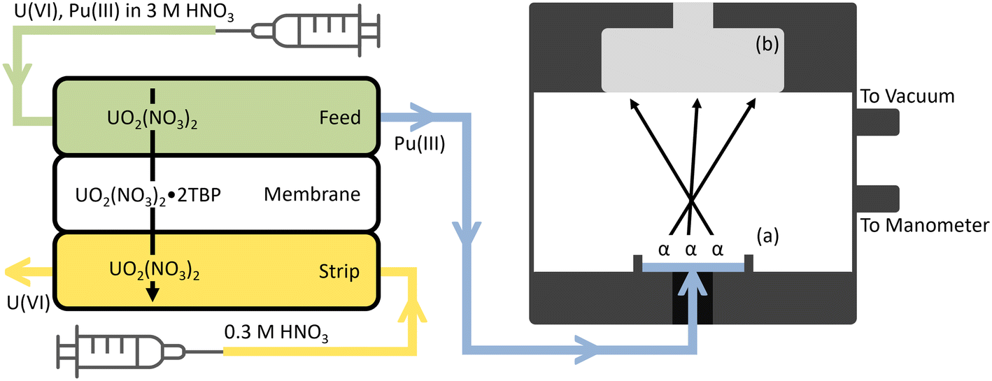 | ||
| Fig. 1 A schematic overview of the deployable radiochemistry platform, not drawn to scale. The feed solution is pumped into the top of the FS-SLM module while the strip solution is pumped counter-currently through the bottom of the FS-SLM module. U(VI) from the feed solution extracts across the membrane and exits through the strip product, while Pu(III) fails to extract and exits through the feed product. A 100 μL sampling of the feed product is then pumped into the reservoir (a) in the bottom of the 3D printed alpha chamber where a vacuum is applied to dry the sample. Alpha particles are released by the dried source and create events in the detector (b) which are characteristic of the radionuclide which emitted them. Fig. S1 and S4† include more details with accurate dimensions for each component. | ||
All alpha spectrometry was performed using a Canberra PIPS 600 mm2 silicon detector utilizing an Ortec 428 Bias supply, an 855 Dual Spec amplifier, and a 927 ASPEC multi-channel analyzer (MCA) powered by an Ortec 4006 Minibin power supply. These electronics are all contained within the 24 × 32 × 35 cm benchtop power supply; if further miniaturization is required, products such as the nanoMCA from Yantel (9.2 × 3.8 × 2.5 cm) may be utilized with a separate bias supply instead. The chamber was evacuated to an ultimate pressure of 20–30 Torr using a 17 W Ametek ALPHA-MINI-PPS vacuum pump (18 × 10.6 × 9.95 cm). All LSC was performed by aliquoting 100 μL of a product stream into 10 mL of Ultima Gold scintillation cocktail and assaying with a Perkin Elmer Tri-Carb 3110TR.
3. Results and discussion
3.1. Effect of stripping acid concentration on extraction yields
Previous work from this group quantitatively extracted U(VI) over a TPB membrane in an FS-SLM module using a 3 M HNO3 feed solution and an H2O stripping solution.19 However, bulk Pu is prone to hydrolysis and colloid formation in water.27 To avoid complications from unwanted hydrolysis, HNO3 was added to the stripping solution and adjusted up to 0.3 M to observe its impact on the U and Pu extraction yields.Triplicate extractions were performed separately for Pu and U to investigate the effect of the stripping acid concentration on extraction yield from 0–0.3 M HNO3 (Fig. 2). Because U and Pu were investigated individually, these extractions were quantified via LSC. Extraction yields for each stream were determined by comparing the activity concentrations in the feed product stream and strip product stream to the activity concentrations in the initial feed stream. No statistically significant difference was observed between any acid concentration within the given range, indicating that the FS-SLM modules can provide consistent results for both Pu and U over a range of stripping acid concentrations with these low-mass tracer solutions. To avoid hydrolyzing conditions for Pu, 0.3 M HNO3 was selected as the stripping solution for subsequent studies. When using a 0.3 M HNO3 stripping solution, the extraction yield of Pu(III) and U(VI) in the feed stream was (98.9 ± 4.0)% and (0.301 ± 0.082)%, respectively; the extraction yield of Pu(III) and U(VI) in the stripping stream was (4.59 ± 0.56)% and (97.5 ± 2.5)%, respectively. The total activity balance was (103.4 ± 4.0)% and (97.8 ± 2.5)% for Pu and U, respectively. The reported uncertainties represent the square root of the external variance in the weighted average of triplicate measurements. For the removal of bulk U from Pu, these extraction yields would predict a decontamination factor (DF) of 330 ± 170 if both elements were introduced into the extraction system together, providing sufficient decontamination of U from Pu for a subsequent isotopic analysis of the Pu stream by alpha spectrometry. Fieldable operations may present with temperatures above or below the typical room temperature of a laboratory; Pu(III) does not form an extraction complex with TBP, so it is not expected to extract at any temperature, while the distribution coefficient of U(VI) into TBP changes slightly from approximately 20–15 within the range of 15–40 °C.28 For these reasons, typical temperature variations aren't expected to impact extraction performance with liquid systems.
 | ||
| Fig. 2 Effect of stripping acid concentration on extraction yields. Fraction of Pu and U in (A) the stripping product stream and (B) the feed product stream. | ||
3.2. Separating and assaying Pu
The mass ratio of Pu/U can vary drastically in post-detonation nuclear debris depending on the ingoing fuel composition and environment factors.2,3,29 Short-lived U isotopes produced during detonation undergo beta decay and may interfere with an isotopic assay of the Pu via pulse-height alpha spectrometry by creating pile-up signals. To reduce the overall beta activity, effective decontamination of U from Pu may be required even in samples with a relatively high Pu/U mass ratio. A 500 μL solution of 233U(VI) and 238Pu(III) was prepared in 3 M HNO3 such that the 238Pu/233U mass ratio was approximately 1 × 10⁻⁴. The 238Pu and 233U activity concentrations were 0.0217 and 0.122 Bq μL−1, respectively, corresponding to an activity ratio of 1.77 × 10⁻¹. This solution was injected into an FS-SLM module and extracted in the same manner as described above. An LSC typically cannot differentiate between two different alpha emitting radionuclides in the same sample, therefore this extraction was assayed via offline alpha spectrometry. Fig. 3 shows the alpha spectra before and after extraction.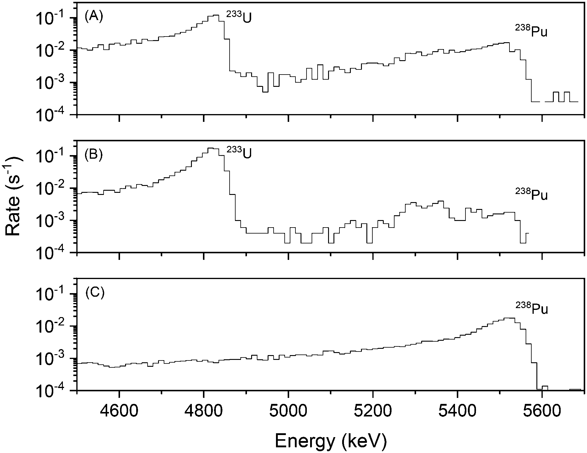 | ||
| Fig. 3 Alpha spectra of (A) feed stock, (B) stripping product, and (C) feed product from a Pu/U separation with a Pu/U mass ratio of 1 × 10⁻⁴. Channels with zero counts cannot be represented on the log scale and appear discontinuous as presented. | ||
The spectrum of the feed stock (Fig. 3A) shows a clear peak for both 233U and 238Pu in the sample. The stripping product (Fig. 3B) shows that 233U(VI) was quantitatively extracted across the membrane and transported out of the stripping stream; the feed product (Fig. 3C) indicates that approximately 96% of the Pu(III) was eluted through the feed, and no detectable amount of U(VI) followed it. The detection limit for 233U in the feed product, set at 3 standard deviations above the 238Pu tail, is 0.015 counts per second (cps), which corresponds to <2% of the 233U signal in the feed stock (<1.2 Bq). Using this detection limit, the DF observed here was ≥52. These results are consistent with the individual element assays via LSC (Fig. 2). Based on the Pu/U DF, the efficacy of the FS-SLM module for the purification of small amounts of Pu from relatively large amounts of U, even at a low mass ratio of 1 × 10⁻⁴, was demonstrated. The most common traditional laboratory technique to separate Pu from excess quantities of U is column chromatography.2,3 This processes may use hundreds of milliliters of acid per sample, require a fume hood, involve significant work-up between each step, and generate large quantities of waste. These requirements present significant challenges for deployable chemistry. Our FS-SLM platform miniaturizes the separation process and allows us to perform a Pu/U separation with less than a milliliter of solution per sample in under one hour while minimizing material resources. The 3D printed FS-SLM platform costs less than 5 USD (ref. 19) and up to four units can be printed and prepared within 24 hours on a single printer. These properties allow the platform to be disposable which helps prevent cross-contamination between multiple samples in the field.
3.3. Alpha chamber development and online isotopic assay of Pu
Multiple iterations of the alpha chamber were printed at different heights ranging from 8–24 mm from the sample to the detector surface. The efficiency and full width at half-maximum (FWHM) for each of the distances tested using a 238Pu source prepared by evaporating a 10 μL aliquot of the 238Pu stock onto an Al planchet is shown in Fig. S5.† The optimum distance was determined to be 12 mm, which was used for all subsequent work. The efficiency and FWHM measured for the given source at this distance were 12% and 37 keV, respectively.Field-deployable applications require simplified and streamlined source preparation, such as direct injection of the product stream from the FS-SLM modules into the bottom of the alpha chamber and immediate evaporation to dryness prior to an online data acquisition. This is readily achievable with this system as a small volume of the product stream (100 μL) is collected and evaporated using the applied vacuum to the chamber. The rate of evaporation was tested in the chamber by aliquoting 100 μL of 0.3 M HNO3 containing 65 Bq of 238Pu directly onto the Al tape covering the bottom of the chamber, evacuating the chamber to approximately 30 Torr, and acquiring data in two-minute intervals. The resolution and count rate in alpha spectrometry are sensitive to the thickness of the radioactive source; therefore, both are expected to increase as the source approaches dryness, reducing degradation within the sample.
Alpha spectra were collected in two-minute intervals over a total of 38 minutes, where t0 represents the time when the vacuum pump was turned on. The fraction of total counts within the 238Pu region of interest (ROI) plotted as a function of time (Fig. 4) indicates that a significant change occurs in the physical source properties around the 16-minute mark. The moment when the sample reaches dryness is unclear, but the ROI fraction approaches and begins to vary around the mean of its final value by the 24-minute mark. This indicates that the source is sufficiently dry to begin an online Pu isotopic assay within 24 minutes after extraction chemistry is complete. The actual data acquisition time can then range from minutes to hours, depending on the Pu concentration in the sample. Traditional laboratory source preparation methods require affixing a solution to a solid surface to create an essentially massless deposit using microprecipitation, evaporation, or electrodeposition. Ideal sources can take up to an hour to complete from beginning to end. The source preparation method described here is relatively fast and requires little input from the operator. The data acquisition time for a given sample is dependent on the total Pu present within the sample, which is characteristic of the sample. Therefore, total acquisition time would be similar when using either this deployable technique or a traditional laboratory technique.
 | ||
| Fig. 4 ROI fractions of an evaporating 238Pu source over time in the 3D printed alpha chamber. The initial liquid source has a low ROI fraction, while the final dry source has a high ROI fraction. The error bars represent the 1σ counting uncertainty; the point at approximately 40 minutes was counted overnight and therefore has a low counting uncertainty. The spectrum collected at 1044 min is considered the final state of the source. | ||
During an assay of post-detonation nuclear debris, a wide range of Pu isotopic distributions may be observed.2,3,29 The principal alpha energies of 239Pu and 240Pu (5156 and 5168 keV, respectively) are not distinguishable with a typical alpha spectrometer. However, a forensic-relevant Pu ratio that can be readily measured by alpha spectrometry is the 238Pu/239,240Pu activity ratio, where the 239,240Pu sum peak is used instead. A 100 μL aliquot of CRM 138 containing approximately 722 Bq of Pu was evaporated onto an Al planchet and measured via offline alpha spectrometry. The CRM 138 isotope standard was used within one month of the purification procedure previously described. The 238Pu/239,240Pu activity ratio was measured as 0.0181 ± 0.0002 on November 3rd, 2021, consistent with the decay-corrected certified 238Pu/239,240Pu activity ratio of 0.0174 ± 0.0017. The Pu isotopic standard NBL CRM 138 was then used to demonstrate the online alpha spectrometric Pu measurement following SLM purification from bulk U.
A 1000 μL feed stock was prepared using CRM 138 Pu and the 1000 ppm U ICP-MS standard in 3 M HNO3 at a Pu/U mass ratio of 1 × 10⁻⁴ (approximately 3.15 × 10⁻⁷ g Pu and 3.15 × 10⁻³ g U). 10 μL of the iron(II) sulfamate stock was added and an online extraction was performed by injecting the feed product stream directly into the bottom of the alpha chamber. The extraction was terminated after 100 μL of the feed product stream was pumped into the alpha chamber (approximately 45 min total); following extraction, the alpha chamber was sealed off from the rest of the microfluidic line using a shut-off valve. The vacuum pump was turned on for 25 minutes to allow the feed product to dry and an alpha spectrum was acquired over 5 hours. Fig. 5 shows the resulting alpha spectrum of the feed product stream with a measured 238Pu/239,240Pu activity ratio of 0.0181 ± 0.0003 on November 5th, 2021, consistent with both the certified value and the previously measured value of the purified CRM 138 Pu. An accurate measure of the 238Pu/239,240Pu activity ratio in a sample with a low Pu/U mass ratio was obtained using the fieldable system in just over 6 hours, with 5 hours devoted to alpha spectrometry. This provides us with the first fieldable radiochemistry platform capable of separating Pu from excess U followed by a forensic evaluation of the Pu-bearing stream. Bringing these traditionally laboratory-based techniques into the field accelerates the pace of nuclear forensics in post-detonation scenarios. The development of this fieldable platform was made possible by the miniaturization of typical laboratory-based techniques into custom 3D printed modules capable of performing microfluidic chemistry coupled directly to alpha spectrometry.
 | ||
| Fig. 5 Alpha spectrum of separated CRM 138 Pu. Spectrum taken over 5 hours following the separation and evaporation of the feed product stream. The feed stock was initially a solution of CRM 138 Pu and U at a 1 × 10⁻⁴ mass ratio. Channels with zero counts cannot be represented on the log scale and appear discontinuous as presented. | ||
4. Conclusion
Improving field-deployable chemistry and assay systems is critically important to reducing forensic timelines following a post-detonation nuclear event. Field-deployable chemical separations for forensic applications are enabled by using microfluidics, and high-resolution 3D printing provides an appropriately fast and customizable platform to develop and test these microfluidic systems. This work demonstrates how microfluidic systems may be implemented for the rapid analysis of Pu in nuclear debris after sample dissolution and debulking steps have already been performed. The platform described here is the first fieldable chemistry system coupled with online alpha spectrometry capable of providing high Pu extraction yields and decontamination from U. Accurate online isotopic assay is ready to begin acquisition within 70 minutes of the start of separations, allowing key measurements to be obtained much earlier in the forensic process compared to traditional laboratory methods. Future work may include coupling multiple SLM modules for customizable, multi-step purifications to separate the Pu and U from a debris sample matrix prior to introduction into this system, and incorporation of alternative online detection systems.Author contributions
KJG performed and analyzed all experiments with support from HFV, NG, TP-D, and JAS. JAS provided supervision and project administration. KJM and AGS conceptualized the idea. All authors participated in the review and editing process.Conflicts of interest
This research received no external financial or non-financial support. This research uses design elements from a pending US patent by Anna G. Servis et al. under application number 16/803,393 titled MODULAR, DISPOSABLE 3D PRINTED MICROFLUIDIC MEMBRANE SYSTEM FOR SEPARATION AND PURIFICATION pending to Lawrence Livermore National Laboratory.Acknowledgements
This work was performed under the auspices of the U.S. Department of Energy by Lawrence Livermore National Laboratory under Contract DE-AC52-07NA27344 and supported by the Laboratory Directed Research and Development Program at LLNL under project 19-ERD-016. We also thank the U.S. Department of Energy's National Nuclear Security Administration, Office of Defense Nuclear Nonproliferation Research and Development, for financial support. This work is released by LLNL under IM number LLNL-JRNL-831572.Notes and references
- M. May, R. Abedin-Zadeh, D. Barr, A. Carnesale, P. Coyle, J. Davis, W. Dorland, W. Dunlop, S. Fetter, A. Glaser, I. Hutcheon, F. Slakey and B. Tannenbaum, Nuclear Forensics: Role, State of the Art, Program Needs, Joint report from the American Physical Society and the American Association for the Advancement of Science, 2008.
- E. C. Morse, in Analytical Methods for Nonproliferation, ed. E. C. Morse, Springer International Publishing, Cham, 2016, pp. 93–105, DOI:10.1007/978-3-319-29731-6_6.
- K. J. Moody, I. D. Hutcheon and P. M. Grant, Nuclear Forensic Analysis, CRC Press, Boca Raton, 2015 Search PubMed.
- J. A. Tilden and D. Boyd, The National Interest, 2021 Search PubMed.
- M. J. Kristo and S. J. Tumey, Nucl. Instrum. Methods Phys. Res., Sect. B, 2013, 294, 656–661 CrossRef CAS.
- K. J. Glennon, E. M. Bond, T. A. Bredeweg, S. S. Chirayath, P. J. O'Neal and C. M. Folden, J. Radioanal. Nucl. Chem., 2021, 330, 57–65 CrossRef CAS.
- M. Wallenius, K. Lützenkirchen, K. Mayer, I. Ray, L. A. de las Heras, M. Betti, O. Cromboom, M. Hild, B. Lynch, A. Nicholl, H. Ottmar, G. Rasmussen, A. Schubert, G. Tamborini, H. Thiele, W. Wagner, C. Walker and E. Zuleger, J. Alloys Compd., 2007, 444–445, 57–62 CrossRef CAS.
- M. Wallenius, P. Peerani and L. Koch, J. Radioanal. Nucl. Chem., 2000, 246, 317–321 CrossRef CAS.
- I. Lantzos, C. Kouvalaki and G. Nicolaou, Prog. Nucl. Energy, 2015, 85, 333–336 CrossRef CAS.
- M. Benedict, T. H. Pigford and L. Hans Wolfgang, Fuel Reprocessing, McGraw-Hill Education, 1981 Search PubMed.
- C. Mariet, A. Vansteene, M. Losno, J. Pellé, J.-P. Jasmin, A. Bruchet and G. Hellé, Micro Nano Eng., 2019, 3, 7–14 CrossRef.
- M. Losno, J. Pellé, M. Marie, I. Ferrante, R. Brennetot, S. Descroix and C. Mariet, Talanta, 2018, 185, 586–591 CrossRef CAS PubMed.
- N. Weeranoppanant, A. Adamo, G. Saparbaiuly, E. Rose, C. Fleury, B. Schenkel and K. F. Jensen, Ind. Eng. Chem. Res., 2017, 56, 4095–4103 CrossRef CAS.
- I. Vural Gürsel, N. Kockmann and V. Hessel, Chem. Eng. Sci., 2017, 169, 3–17 CrossRef.
- H. Zhang, H. Wang, X. Luo, D. Y. C. Leung, Q. Pang, H. Xu, L. Zhang and J. Xuan, Chem. Eng. J., 2019, 356, 673–679 CrossRef CAS.
- M. Rodas Ceballos, F. González Serra, J. M. Estela, V. Cerdà and L. Ferrer, Talanta, 2019, 196, 510–514 CrossRef CAS PubMed.
- J. Qiao, Molecules, 2020, 25, 1462 CrossRef CAS.
- A. G. Servis, T. Parsons-Davis, K. J. Moody and N. Gharibyan, Ind. Eng. Chem. Res., 2021, 60, 6344–6354 CrossRef CAS.
- A. G. Servis, T. Parsons-Davis, K. J. Moody and N. Gharibyan, Ind. Eng. Chem. Res., 2021, 60, 629–638 CrossRef CAS.
- M. F. San Román, E. Bringas, R. Ibañez and I. Ortiz, J. Chem. Technol. Biotechnol., 2010, 85, 2–10 CrossRef.
- M. A. Malik, M. A. Hashim and F. Nabi, Chem. Eng. J., 2011, 171, 242–254 CrossRef CAS.
- E. Browne and J. K. Tuli, Nucl. Data Sheets, 2007, 108, 681–772 CrossRef CAS.
- E. Browne and J. K. Tuli, Nucl. Data Sheets, 2014, 122, 205–292 CrossRef CAS.
- E. Browne and J. K. Tuli, Nucl. Data Sheets, 2006, 107, 2649–2714 CrossRef CAS.
- M. S. Basunia, Nucl. Data Sheets, 2006, 107, 2323–2422 CrossRef CAS.
- E. Browne and J. K. Tuli, Nucl. Data Sheets, 2015, 127, 191–332 CrossRef.
- D. L. Clark, S. S. Hecker, G. D. Jarvinen and M. P. Neu, in The Chemistry of the Actinide and Transactinide Elements, ed. L. R. Morss, N. M. Edelstein and J. Fuger, Springer Netherlands, Dordrecht, 2006, pp. 813–1264, DOI:10.1007/1-4020-3598-5_7.
- E. A. Puzikov, B. Y. Zilberman, Y. S. Fedorov, I. V. Blazheva, A. S. Kudinov, D. V. Ryabkov and O. V. Shmidt, Radiochemistry, 2015, 57, 136–142 CrossRef CAS.
- R. C. Haight, M. B. Chadwick and D. J. Vieira, Los Alamos Sci., 2006, 30, 53–69 Search PubMed.
Footnotes |
| † Electronic supplementary information (ESI) available. See DOI: https://doi.org/10.1039/d2lc00391k |
| ‡ Present address: Argonne National Laboratory, Lemont, IL 60439, USA. |
| This journal is © The Royal Society of Chemistry 2022 |