
 Open Access Article
 This Open Access Article is licensed under a Creative Commons Attribution-Non Commercial 3.0 Unported Licence
Centrifugal disc liquid reciprocation flow considerations for antibody binding to COVID antigen array during microfluidic integration†
Alexander T.
Hwu‡
 *a,
Masoud
Madadelahi‡
b,
Rie
Nakajima
c,
Ehsan
Shamloo
d,
Alexandra
Perebikovsky
d,
Horacio
Kido
d,
Aarti
Jain
c,
Algis
Jasinskas
c,
Shawna
Prange
e,
Philip
Felgner
c and
Marc
Madou
*ab
*a,
Masoud
Madadelahi‡
b,
Rie
Nakajima
c,
Ehsan
Shamloo
d,
Alexandra
Perebikovsky
d,
Horacio
Kido
d,
Aarti
Jain
c,
Algis
Jasinskas
c,
Shawna
Prange
e,
Philip
Felgner
c and
Marc
Madou
*ab
aDepartment of Chemical and Biomolecular Engineering, University of California, Irvine, 6000 Interdisciplinary Science & Engineering Building, Irvine, CA 92617-2580, USA. E-mail: alexanderthwu@gmail.com; mmadou@uci.edu
bSchool of Engineering and Sciences, Tecnologico de Monterrey, Ave. Eugenio Garza Sada 2501, Monterrey 64849, NL, Mexico
cSchool of Medicine, University of California, Irvine, 1001 Health Sciences Rd, Irvine, CA 92617, USA
dAutonomous Medical Devices Incorporated, 3511 Sunflower Avenue, Santa Ana, CA 92704, USA
eGrace Bio Labs, 1015 Emkay Drive, Bend, Oregon 97702, USA
First published on 21st June 2022
Abstract
Heterogeneous immunoassays (HI) are an invaluable tool for biomarker detection and remain an ideal candidate for microfluidic point-of-care diagnostics. However, automating and controlling sustained fluid flow from benchtop to microfluidics for the HI reaction during the extended sample incubation step, remains difficult to implement; this leads to challenges for assay integration and assay result interpretation. To address these issues, we investigated the liquid reciprocation process on a microfluidic centrifugal disc (CD) to generate continuous, bidirectional fluid flow using only a rotating motor. Large volumetric flow rates (μL s−1) through the HI reaction chamber were sustained for extended durations (up to 1 h). The CD liquid reciprocation operating behavior was characterized experimentally and simulated to determine fluid flow shear rates through our HI reaction chamber. We demonstrated the continuous CD liquid reciprocation for target molecule incubation for a microarray HI and that higher fluid shear rates negatively influenced our fluorescence intensity. We highlight the importance of proper fluid flow considerations when integrating HIs with microfluidics.
Introduction
Heterogeneous assays (HIs) are a ubiquitous tool for biomarker characterization and laboratory-based medical diagnostics. The assays utilize surface-immobilized capture molecules to selectively bind and retain corresponding target molecules from a liquid sample to produce a signal for detection.1 Many innovations surrounding different aspects of the assay, including immobilization substrates, functionalization chemistries, capture-target interactions, and detection methods, result in a versatile platform spanning a large range of applications, such as porous membranes to determine protein expression (western blot),2 well-plates for antigen–antibody detection (enzyme-linked immunosorbent assay, ELISA),3 and microfluidic chips for ligand-receptor affinity characterization (surface plasmon resonance, SPR).4 While seemingly disparate, all these heterogeneous immunoassays operate on the same concept: capturing and retaining enough target molecules required for detection.The heterogeneous immunoassay requires sufficient reaction during sample-substrate incubation to ensure adequate target molecule capture for consistent assay results, severely restricting the valuable potential of HIs for point-of-care (PoC) diagnostics due to long incubation durations. During sample-substrate incubation, target molecules in the liquid diffuse and react with the surface-immobilized capture molecules, decreasing the analyte concentration near the sensor surface and forming a steadily increasing depletion layer. Over time, molecules must diffuse longer distances before reaching the reaction surface, resulting in variable incubation times, and depending on the concentrations and interactions between the capture-target molecules (reaction kinetics), can range from several minutes to overnight.5–7
Flow advection, such as on orbital shakers for self-contained dishes and well-plates or continuous flow through a reaction chamber, minimizes the depletion layer formation, reduces incubation times (western blot or ELISA), and even allows real-time monitoring of analyte binding for applications like SPR.8 However, incorporating advection adds an additional layer of complexity to the system, meaning the HI results become dependent on advection properties, such as fluid velocity. While long incubation times may be acceptable for standard laboratory tests, generating controllable fluid flow through a reaction chamber for self-contained microfluidics (i.e. without pumps or external connections) remains difficult, preventing PoC HI adoption.
To tackle these limitations, some researchers use bead-based immunoassays in which functionalized beads are free to move. Hence, by moving the beads, target molecules in the liquid can reach capture sites on the beads.9,10 In another easy and typical alternative method, researchers utilize liquid reciprocation to generate continuous, sustained flow from a finite liquid sample injected onto a microfluidic device. The liquid reciprocation design is simple, requiring only three fluidic features (a reaction chamber connected at opposite ends to two liquid reservoirs), a pressure-driving source, and three operating steps: 1) liquid is loaded into the first reservoir; 2) the liquid is pushed (or pulled) to the second reservoir, generating flow through the reaction chamber; and 3) liquid is pushed (or pulled) back to the first reservoir, reversing the flow through the reaction chamber. By repetitively transferring the fluid between the two reservoirs (step 2 and step 3) using a combination of push and/or pull actuation, continuous, bidirectional flow is sustained through the reaction chamber. The technique has been successfully demonstrated using different pressure regulation techniques. For example, Kim et al.11 attached a pipette to one chamber and reciprocated the liquid by repetitive up-down pipetting, while Liu et al.12 attached a water bottle to reciprocate liquid through a reaction chamber by manually squeezing-releasing the water bottle; and for user-free actuation, Noroozi et al. utilized counteracting centrifugo-pneumatic forces during acceleration-deceleration to reciprocate liquid through the reaction chamber on a microfluidic centrifugal disc (CD).13 Automating and controlling the liquid reciprocation (LR) fluid flow conditions are critically important for consistent HI results.
We investigate and characterize the fluid flow behavior through a reaction chamber for CD LR, which utilizes counteracting centrifugal and pneumatic forces during endless acceleration-deceleration cycles to generate bidirectional fluid flow through a microchannel and reaction chamber connecting a receiving reservoir and pneumatic reservoir seen in Fig. 1. At a low rotational frequency, pneumatic pressure prevents fluid flow into the pneumatic reservoir. Accelerating to a higher rotational velocity increases the rotational forces, resulting in fluid flow from the receiving reservoir to the pneumatic reservoir. Liquid entering the pneumatic reservoir displaces and compresses the gas in the gas compartment, storing the compressed gas as a counteracting pneumatic force. During deceleration, the liquid flow is reversed from the pneumatic reservoir to the receiving reservoir due to the pneumatic force counteracting the decreasing rotational forces. By continuously accelerating and decelerating, a finite-volume sample containing target molecules loaded into the CD is constantly advected over the reaction surface immobilized with capture molecules.
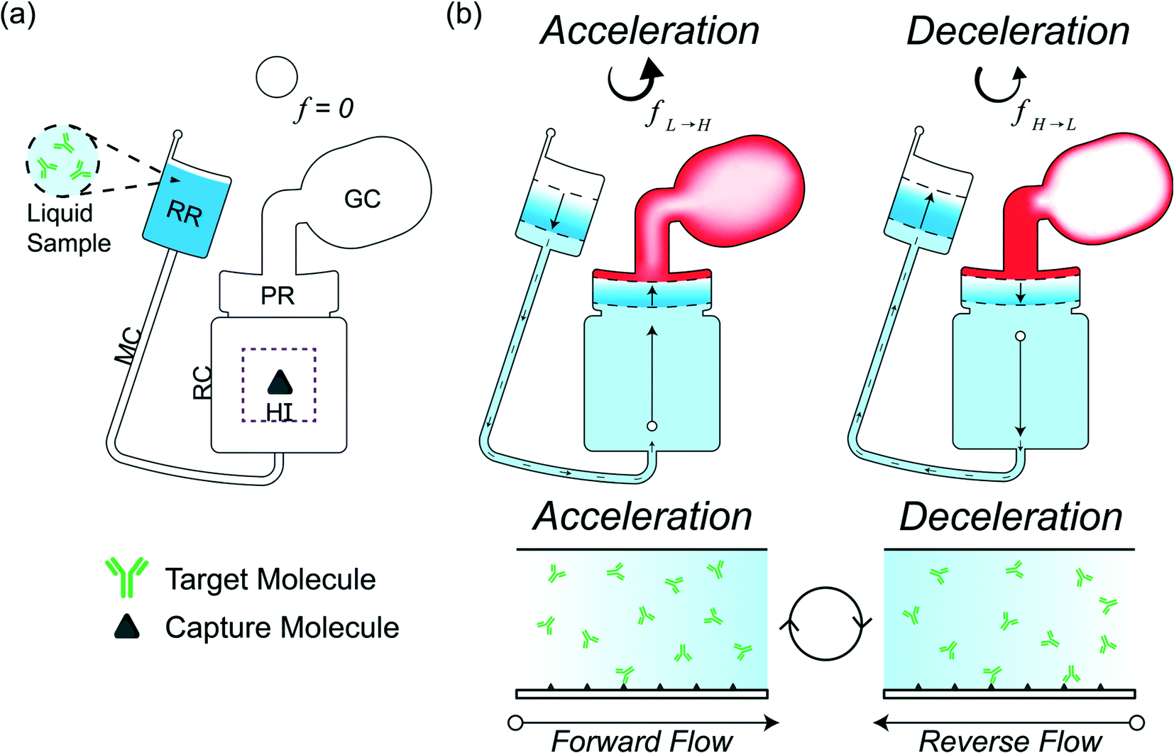 | ||
| Fig. 1 (a) CD LR chamber design for a finite-volume of liquid with abbreviations: receiving reservoir (RR), microchannel (MC), reaction chamber (RC), heterogeneous immunoassay (HI), pneumatic reservoir (PR), and gas compartment (GC). (b) CD LR operation during acceleration-deceleration illustrating flow between the RR and PR (top); side view of RC during operation (bot). | ||
In this work, we demonstrated reciprocation flow control through a reaction chamber designed for HI integration on a CD. Continuous acceleration–deceleration (acc–dec) cycles between a low and high rotation frequency, generate continuous fluid flow (and fluid advection over the reaction surface). By modifying the acc-dec ramp rates and lower and upper rotation frequencies, different flow rates are established through the reaction chamber. We simulated the process to determine flow characteristics. Finally, we tested and established the CD LR flow conditions for the direct capture of fluorophore-labeled antibodies on a microarray HI (referred to as microarray from here on out) and demonstrate the critical role of proper flow implementation towards PoC when translating HI assays from benchtop to microfluidics.
Theoretical background
Heterogeneous immunoassay transport considerations for point-of-care
Heterogeneous immunoassays rely on a reaction between target molecules in an aqueous solution (species A) and capture molecules immobilized on a solid surface (species B). Detection requires sufficient formation of the reaction product (species AB) seen in Scheme 1.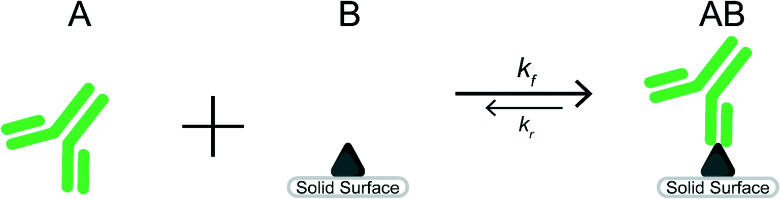 | ||
| Scheme 1 Reaction between species A and species B to form species AB. | ||
The ideal situation often used to examine the heterogeneous immunoreaction between a target molecule (species A) and capture molecule (species B) forming a target-capture complex (species AB) can be seen in eqn (1) as
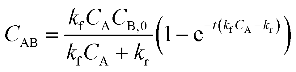 | (1) |
Operating principle of liquid reciprocation on a CD
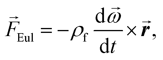
Centrifugal microfluidics uses rotational forces to generate forward flow and pneumatic forces to generate reverse flow. The three rotational forces are the centrifugal force (eqn (1)), Coriolis force (eqn (2)), and Euler force (eqn (3)):![[F with combining right harpoon above (vector)]](https://www.rsc.org/images/entities/i_char_0046_20d1.gif) cent = −ρf cent = −ρf![[small omega, Greek, vector]](https://www.rsc.org/images/entities/b_i_char_e13e.gif) × ( × × ( × ![[r with combining right harpoon above (vector)]](https://www.rsc.org/images/entities/b_i_char_0072_20d1.gif) ), ), | (2) |
Cor = −2ρf × ![[u with combining right harpoon above (vector)]](https://www.rsc.org/images/entities/b_i_char_0075_20d1.gif) f, f, | (3) |
 | (4) |
is the angular velocity vector,  is the rate of change in angular velocity, f is the velocity vector of any fluidic element, and is the radial position vector. The centrifugal force always acts radially outward and is the dominant force driving fluid flow due to the angular velocity squared (Fcent ∼ ω2). Meanwhile the Coriolis force and Euler force both act to modify the fluid flow direction with the Coriolis force dependent on the angular velocity and fluid velocity through the right-hand rule and the Euler force dependent on the rate of change in angular velocity. The angular velocity, ω with units rad s−1, is commonly used interchangeably with rotation frequency, f with units Hz, which differs by a factor of 2π (ω = 2πf). In this paper, we exclusively use rotation frequency, f, to avoid confusion. Pneumatics are incorporated to generate radially inward flow through a non-vented chamber design. When liquid enters and displaces the gas in a non-vented chamber, a pneumatic force is generated due to the gas compression, acting on all surfaces in the chamber, including the gas–liquid interface. The pneumatic force is shown in eqn (4) as
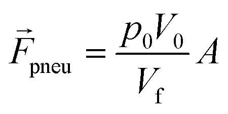 | (5) |
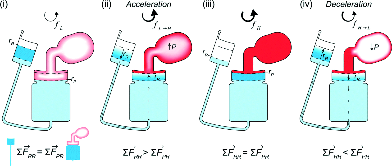 | ||
| Fig. 2 Stages of CD LR. At a low rotation frequency (i) the forces acting on each column are equal (RR and PR) resulting in the liquid radial positions rR and rP. Acceleration (ii) increases the centrifugal force, causing liquid to flow from the RR to the PR and the pressure in the GC to increase until the high rotation frequency (iii). Deceleration reverses the process (iv). | ||
The design for CD LR consists of a receiving reservoir and a non-vented pneumatic reservoir with a gas compartment, connected radially outward through a microchannel and reaction chamber, respectively, forming two liquid columns. The ends of the two columns are connected using a radial channel. When the CD is subject to a constant rotational frequency, a self-contained volume of liquid initially occupying the receiving reservoir is transferred into the pneumatic reservoir until the forces acting on the receiving reservoir liquid column equilibrate with the forces acting on the pneumatic reservoir liquid column. The additional pneumatic force acting on the pneumatic reservoir liquid column, resists flow, resulting in more fluid occupying the receiving reservoir liquid column. At equilibrium, the sum of the predominate forces in each column (eqn (5)) is
| ∑RR = cent + Cor ≡ cent + Cor + pneu = ∑ PR | (6) |
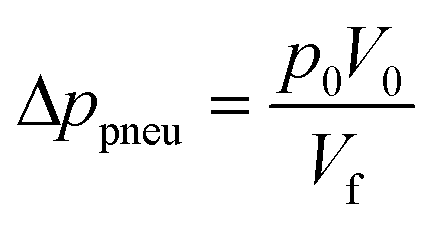
In other publications, the force balance analysis is often approximated by translating the three-dimensional force equation into a two-dimensional pressure difference described by the radial liquid positions in each reservoir (measured from the center of the disc). When the fluid is transferred from the RR to the PR due to increasing rotational frequency, the corresponding radial positions of the liquid, rR and rP, increases and decreases, respectively and vice versa when fluid is transferred from the PR to the RR. The dynamic centrifugal pressure approximated from the radial positions is seen in eqn (6) and the pneumatic pressure difference becomes eqn (7).
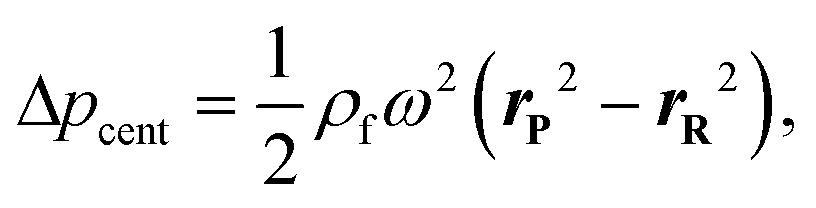 | (7) |
 | (8) |
Materials and methods
Microfluidic disc design and fabrication
Microfluidic centrifugal discs (CDs) were designed in CAD (SolidWorks) and fabricated from poly(methyl methacrylate) (PMMA). Injection molded discs were obtained from Protolabs. Chambers were sealed using pressure sensitive adhesive (9795R, 3M) and arrays were assembled into the disc using ultraviolet curable adhesive.A spin stand assembly was used to spin the CDs for fluidic actuation. A piece of reflective foil was placed on the edge of the CD and the CD was placed onto the custom spin chuck attached to the shaft of a DC motor (BLWS235D-36V-4000-1250SI, Anaheim Automation) with an optical encoder. A stepper controller (EZSV23WV, All Motion) wired to the motor and optical encoder provided feedback control. The motor was spun by sending commands to the controller using software (EZCommander) or through Python-written scripts. Fluidic flow was recorded during rotation using the sensor-camera assembly. A fiber optic sensor (PBT46U, Banner Engineering) with a trigger (D10DPFP, Banner Engineering) detected the reflective foil at each revolution, signaling the stroboscope (DT-311A, Shimpo) to flash and the camera (acA800-510uc, Basler or CR14-1.0-16C-NL, Kron Technologies) to acquire an image.
Reciprocation experiments were carried out on the spin stand. Briefly, 50 μL of fluid was injected into the disc and the disc was secured onto the spin chuck. The commands were issued, subjecting the disc to extended acc–dec cycles, and the process was recorded. The radial liquid positions were determined from the liquid column heights extracted from recorded video frames. Frames were extracted from the native video (AVI format) and analyzed using OpenCV in Python. The camera resolution (800 × 600) provided a 46 pixel per mm precision with an approximate uncertainty of ±3 pixels due to the edge detection algorithm. For fluid visualization experiments, 10 μL of dyed water (measured density = 1.05 g cm−3) was loaded into the pneumatic reservoir and sealed, while 40 μL of DI water was loaded into the receiving reservoir.
Microarray materials and fabrication
Materials and reagents used to fabricate the microarray consisted of glass-supported substrates, proteins, and buffers. The glass-supported nitrocellulose was obtained from Grace Bio-Labs (Oncyte Avid 305![[thin space (1/6-em)]](https://www.rsc.org/images/entities/char_2009.gif) 116); trehalose (90210) was obtained from Millipore Sigma; phosphate buffered saline (PBS) (10010023) and tris-buffered saline (TBS) (28358) were obtained from Thermo Fisher Scientific. His-tag SARS-CoV Spike/RBD [Spike] (40150-V08B2) was obtained from Sino Biological. Alexa-647 conjugated streptavidin [Strep647] (S21374), biotinylated-bovine serum albumin [b-BSA] (29130), human IgG isotype control (31154), and human IgM isotype control (31146) were obtained from Thermo Fisher Scientific. Streptavidin conjugated gold nanoparticles [Strep–AuNP] with 150 nm diameter (GSIR150-1M) were obtained from nanoComposix. Before printing proteins were diluted with printing buffer (trehalose (1% w/v) in PBS or TBS) and the back of the glass supporting the nitrocellulose was scored using a laser etcher to obtain sixteen 9 × 9 mm squares centered around each 6.5 × 6.5 mm pad.
116); trehalose (90210) was obtained from Millipore Sigma; phosphate buffered saline (PBS) (10010023) and tris-buffered saline (TBS) (28358) were obtained from Thermo Fisher Scientific. His-tag SARS-CoV Spike/RBD [Spike] (40150-V08B2) was obtained from Sino Biological. Alexa-647 conjugated streptavidin [Strep647] (S21374), biotinylated-bovine serum albumin [b-BSA] (29130), human IgG isotype control (31154), and human IgM isotype control (31146) were obtained from Thermo Fisher Scientific. Streptavidin conjugated gold nanoparticles [Strep–AuNP] with 150 nm diameter (GSIR150-1M) were obtained from nanoComposix. Before printing proteins were diluted with printing buffer (trehalose (1% w/v) in PBS or TBS) and the back of the glass supporting the nitrocellulose was scored using a laser etcher to obtain sixteen 9 × 9 mm squares centered around each 6.5 × 6.5 mm pad.
Array printers were used to deposit protein spots onto the glass-supported nitrocellulose substrates. IgG and IgM were spotted (1 nL) in triplicates at four concentrations in serial dilutions (2:5) starting at 0.15 mg mL−1 for IgG and 0.95 mg mL−1 for IgM. The Strep647 and Spike protein spots (150 μm diameter) were printed in quintuplicates on each substrate at eight concentrations. The eight printing concentrations corresponded to a binding density range of approximately 7.8 × 10⁻⁷ mole per m2 to 6.1 × 10⁻⁹ mole per m2. The b-BSA, with a degree of biotinylation of 10, was printed at a concentration of 7.8 × 10⁻⁸ mole per m2 to obtain an equivalent binding site ratio to the printed Strep647. The Strep–AuNP was printed by depositing 1 μL onto the nitrocellulose surface. The glass slide containing sixteen printed arrays was diced into sixteen individual 9 × 9 mm arrays before assembly into the CDs. Printed and CD-assembled arrays were stored in a nitrogen desiccator at room temperature until use.
Microarray testing
Reagents used to test the microarray included the sample diluent (10485356) obtained from GVS Filter Technologies, wash buffer (1× tris-buffered saline with Tween; TBS-T) (28360) obtained from Thermo Fisher Scientific, and test antibodies. Alexa-647 goat anti-human IgG (109-605-170) and Alexa-647 goat anti-human IgM (109-606-129) used to probe the IgG/IgM spots were obtained from Jackson ImmunoResearch. Recombinant anti-SARS-CoV-2 spike glycoprotein S1 monoclonal antibody [anti-Spike] (CR3022; ab273073) used to probe the Spike spots was obtained from Abcam. The test antibody, anti-Spike, was conjugated with Alexa-647 using commercially available kits (S10900 & S10906, Thermo Fisher Scientific) as per manufacturer instructions and stored at 4 °C in PBS containing 0.01% (w/v) sodium azide. Final stock concentrations were measured (Nanodrop 2000, Thermo Fisher Scientific) and degree-of-labeling (DoL) was calculated as recommended (DoL = molesdye per molesIgG). The final concentration of the anti-S1 was 1.24 mg mL−1 (DoL = 2.0). Test samples were diluted to appropriate concentrations in the sample diluent before incubation experiments.Reciprocating flow over the microarray surface was performed by loading the test samples into the CD and subjecting the CD to multiple acc–dec cycles for various durations. After the incubation time, the test sample was aspirated and replaced with 50 μL of wash buffer (TBS-T) and reciprocated for 2 minutes between 20 and 100 Hz with acc–dec rate of 160 Hz s−1 for 2 min. After the reciprocation wash, the buffer was aspirated, the array was disassembled from the disc, dried, and imaged for fluorescence intensity.
Benchtop incubation was performed by assembling the glass slide with the array-slide system obtained from Grace Bio-Labs (204860). Samples (100 μL) were loaded into the wells and the array-slide system was agitated on a microplate shaker (88-861-023, Fisher Scientific) at 700 RPM for the designated time. After incubation, the samples were aspirated, and the arrays were washed three times using TBS-T (100 μL) for 5 minutes each at 700 RPM. Following the last wash step, the slides were disassembled from the array-slide system, placed into a 50 mL conical tube, and centrifuged for 1 min at 4000 RPM (5702, Eppendorf) to dry the microarrays before fluorescence imaging. The captured antibodies on the surface remain stable when dried.
Fluorescence imaging, quantification, and analysis
Fluorescence images of the arrays were obtained using a compact fluorescence microscope camera. The compact microscope camera (AM4117MT-DFRW, Dino-Lite, Taiwan) equipped with 620 nm excitation LEDs and a 655 nm high-pass emission filter was placed in an additional light-blocking enclosure to eliminate ambient or stray light. The arrays were placed in the same orientation and position and images were acquired using multiple exposure settings (0.125, 0.25, 0.5, and 1.0 s) within the camera's linear range with no white balance and at a constant ISO (ISO = 800) resulting in a 20 pixel spot diameter. Images were imported into Image Studio (Licor) and quantified as the intensity minus a 3 pixel median border background. Quantified fluorescence intensities obtained using the compact fluorescence microscope was previously cross-verified using an inverted microscope (BZ-X810, Keyence) and a confocal microscope (SP8, Leica). Two-way ANOVA with Tukey post hoc was performed in OriginLabs between time-points and test groups (p < 0.05).Results and discussion
Liquid reciprocation flow control and simulation
The microfluidic disc design for HI integration can be seen in Fig. 3a. Side 1 contains the primary features previously described (RR, PR, GC, and MC) with an additional inlet chamber and wide channels for fluid handling. Side 2 contains the reaction chamber for the HI array integration. Side 1 and Side 2 are connected using the through features (Fig. 3a, top, yellow fill). The selected operating frequencies, fL = 20 Hz and fH = 100, ensured the receiving reservoir and pneumatic reservoir was partially filled during acc–dec. For 50 μL of fluid, the initial volumes of liquid occupying the reservoirs at 20 Hz was approximately 38 μL in the RR with dimension 4 mm × 2.5 mm (W × D) at a radial position of 16.2 mm (rR); 1.75 μL in the PR with dimension 7 mm × 2.5 mm (W × D) at a radial position of 22.9 mm (rP); and a combined volume of 10.25 μL in the connecting features. During initial sample loading, the gas occupying the connecting features was displaced into the pneumatic reservoir and gas compartment resulting in a slightly elevated pressure at the starting operating frequency ( ). We recorded the dynamic displacement of the fluid meniscus in the receiving reservoir and pneumatic reservoir at two acc-dec ramp rates (160 Hz s−1 and 16 Hz s−1). The radial liquid positions from the center of the disc were determined by measuring the fluid column height in each chamber and calculated accordingly (Fig. 3b). Fast CD LR was defined using an acc–del ramp rate of 160 Hz s−1 with a total cycle time of 1 second (τ = 1 s) while, slow LR was defined using an acc–dec ramp rate of 16 Hz s−1 with a total cycle time of 10 seconds (τ = 10 s).
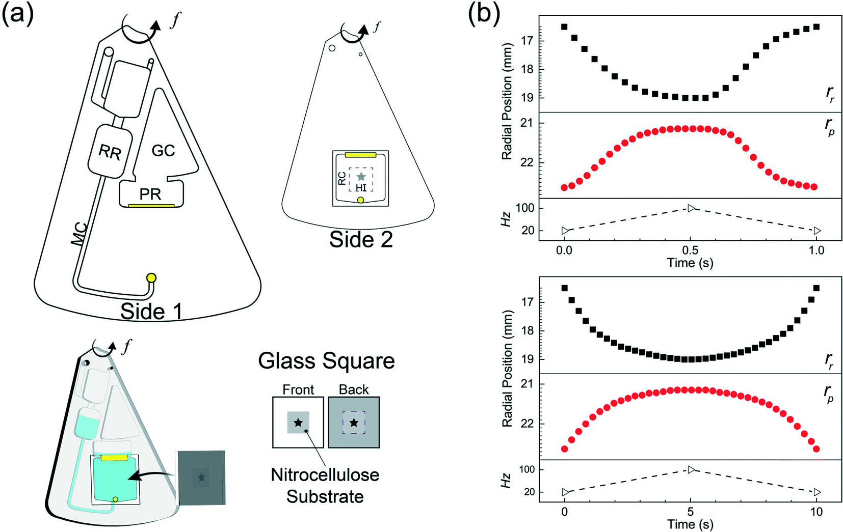 | ||
| Fig. 3 (a) A section of the CD used for LR with the primary features labeled (top) and a 3-D illustration of the HI integration with the RC (bot). (b) Measured radial liquid positions during the reciprocation process for a fast LR (top; τ = 1 s, ramp rate = 160 Hz s−1) and slow LR (bot; τ = 10s, ramp rate = 16 Hz s−1). | ||
We analyzed the radial position measurements and identified interesting characteristics pertaining to the centrifugal and pneumatic forces at play. Both cycles (τ = 1 s & 10 s), reflect the same radial positions at the low rotation frequency (rR ∼ 16.2 mm; rP ∼ 22.9 mm) and high rotational frequency (rR ∼ 18.8 mm; rP ∼ 21.4 mm) but exhibit different profiles in between. The fast CD LR cycle (τ = 1 s at 160 Hz s−1), provides quick, rapid liquid transfer from one chamber to the next and vice versa in the deceleration step. Acceleration drives liquid at a linear rate (t = 0–0.35 s) until the pneumatic force becomes proportional to the centrifugal force (Fcent ∼ Fpneu). When the pneumatic pressure starts hindering fluid transfer (t = 0.35–0.5 s), increasing rotational frequency continues to facilitate fluid flow due to the scaling of the centrifugal and pneumatic force (Fcent ∼ ω2 ≡ (2πf)2vs. Fpneu ∼ V0/Vf).19 During deceleration, liquid flow only reverses after the rotational frequency (t ≈ 0.6 s) decreases past the threshold required for pneumatic forces to overcome centrifugal forces. Further decrease below the threshold frequency greatly reduces the centrifugal force, allowing for rapid gas expansion and generating a reverse flow rate slightly greater, albeit shorter, than the acceleration step. Towards the end of the cycle, the reverse flow decreases due to depleted pneumatic forces. The behavior observed for the slower reciprocation cycle (τ = 10s at 16 Hz s−1) can be explained using the same rational. The centrifugal force dominates (t = 0–2 s), driving fluid flow into the pneumatic reservoir until the pressure build up in PR-GC in the pneumatic head space impedes further fluid displacement (t = 2.5–5 s). Compared to the cycle with a ramp rate of 160 Hz s−1, the fluid flow during the deceleration step reflects a strikingly different behavior. Instead of the rapid gas expansion driving reverse fluid flow, reverse flow for a slow deceleration (16 Hz s−1) is controlled by the same counteracting centrifugal and pneumatic force, mirroring the profile observed in the acceleration step.
To reiterate, the acceleration ramp rate controls forward flow while counteracting centrifugo-pneumatic forces control revere flow. Forward flow depends critically on increasing the rotational frequency and is proportional to the ramp rate. On the other hand, reverse flow relies on gas expansion. For an instantaneous deceleration (τdec = 0.5 s at 160 Hz s−1), once the rotational frequency decreases past a threshold frequency, the centrifugal forces counteracting the pneumatic compression quickly dissipate, allowing for flow reversal via rapid gas expansion (Fpneu ≫ Fcent). In contrast, during a slow deceleration step (τdec = 5 s at 16 Hz s−1), the counteracting centrifugal and pneumatic forces remain proportional (Fpneu ∼ Fcent).
To identify fluid flow behavior through the reaction chamber during the acc–dec process, we simulated the reciprocation process using the experimentally measured radial positions. The liquid domain was extracted from the initial fill levels of the geometric design and the receiving reservoir and pneumatic reservoir were implemented as a moving mesh to reflect the radial liquid positions. By using the empirical radial positions (Δr) as the velocity boundary conditions on the liquid–air interface of the receiving reservoir and pneumatic reservoir, we overcome two challenging tasks associated with CD LR fluid simulations: 1) obtaining appropriate boundary conditions; and 2) eliminate the need to directly simulate the gas-phase behavior. Without this experimentally implemented simulation, the two-phase simulation between the liquid and gas in the pneumatic reservoir and gas compartment, respectively, would result in time-consuming (on the order of milliseconds) and computationally expensive simulation. The balance between centrifugal and pneumatic forces are inherently captured through the moving liquid domains; and in general, using experimentally measured radial positions is a good strategy for avoiding difficulties selecting appropriate boundary conditions for CD fluid simulation even if moving meshes are not used.
We validated the model before extracting the flow velocity in the RC from the simulation results. We compared the experimentally calculated and simulated liquid volumes in the receiving and pneumatic reservoirs (Fig. 4) suggesting that the time step of 1/100 of the reciprocation cycle time was adequate in capturing the volumetric transfer. Additionally, we compared the dye mixing to the simulation streamlines in the receiving reservoir (Fig. 4, insets) for fast CD LR (Video S1†) and slow CD LR (Video S2†). To quickly explain, the acceleration generates vortical flow, also simulated by Ren et al.,20 due to a combination of the Euler acceleration and no-slip wall conditions. During deceleration, the dye returning into the receiving reservoir for a fast ramp rate (160 Hz s−1), extends towards the upper meniscus radial position (Fig. 4, top, inset; t = 0.7 s & 0.8 s). In contrast, the centrifugal force remains prominent in the receiving reservoir during slow deceleration (16 Hz s−1), resulting in stacked fluid layers (Fig. 4, top, inset; t = 6 s). After validating the simulation, we found the integrated average shear rate in the reaction chamber to be 2500 s−1 for the fast CD LR (τ = 1 s at 160 Hz s−1) and 580 s−1 for the slow CD LR (τ = 10 s at 16 Hz s−1). To investigate the shear rate effects during HI assay integration, we assigned the shear rate as an order-of-magnitude approximation for the fast CD LR (2500 s−1 ≈ 103 s−1) and slow CD LR (580 s−1 ≈ 102 s−1).
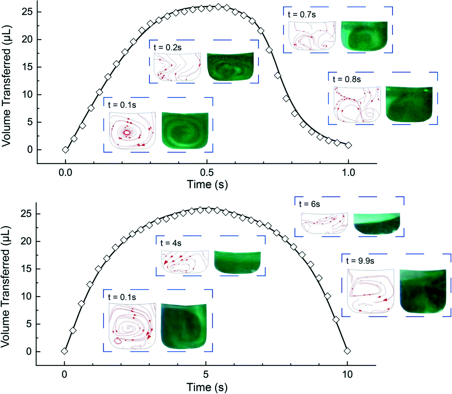 | ||
| Fig. 4 Comparison between calculated experimental (◇) and simulated (line) volume transfer during fast LR (top) and slow LR (bottom). Insets compare experimental fluid mixing and simulated streamlines. | ||
Heterogeneous immunoassay integration and troubleshooting
To test the CD LR on the HI, we assembled the arrays with capture molecules made up of human IgG and human IgM spots on a nitrocellulose substrate and incubated highly reactive, fluorophore-labeled 2nd antibodies (goat-anti-human IgG and goat-anti-human IgM), as the target molecule at a concentration of 100pM. An orbital shaker was also used as a control during the benchtop-to-microfluidic transition. The characteristic shear rate of the fluid in a 96-well plate on an orbital shaker was ∼10 s−1 at an orbital frequency of 700 RPM.21 Between the three forms of advection, the benchtop orbital shaker had the lowest shear rate of ∼10 s−1, followed by the slow CD LR with shear rate of ∼102 s−1, and ending with the fast CD LR with the highest shear rate of ∼103 s−1.We hypothesized that the reaction system with largely favorable kinetics (kf ∼ 1 × 10⁶ M−1 s−1, kr ∼ 1 × 10⁻³ s−1) would benefit from the advection with increasing shear rates yielding higher fluorescence intensities. Incubation was tested and compared between the two different CD LR cycles, on the benchtop orbital shaker, and at static conditions for a 15-, 30-, and 60-minute incubation duration. The mean fluorescence intensity (MFI) results of the IgG (Fig. S1†) and IgM (Fig. 5) support the typical expectation that advection does indeed improve the assay results.
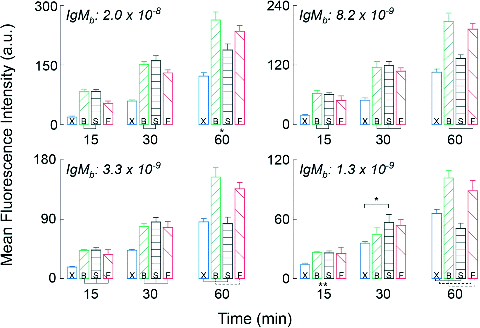 | ||
| Fig. 5 Mean fluorescence intensity of IgM spots obtained after 15, 30 and 60 minutes of incubations for different capture molecule concentrations and incubation conditions. X: Static incubation; B: benchtop orbital (shear rate ∼101 s−1); S: slow CD LR (shear rate ∼102 s−1); F: fast CD LR (shear rate ∼103 s−1). *All results significantly different (p < 0.05) unless indicated by solid/dotted tie lines or (**). Error bars represent ± SD from n = 3 independent samples. | ||
The most apparent trends between the three forms of advection are observed for the mean fluorescence intensities obtained on the IgM spots at the highest immobilization concentration (top left, Fig. 5). By using advection – benchtop orbital, slow CD LR, or fast CD LR – the mean fluorescence intensity was increased two-fold compared to the static incubation across all incubation durations. However, the typical statement that increasing shear rate increases fluorescence intensities is not obvious. After 15 and 30 minutes of incubation, the mean fluorescence intensities obtained using the fast CD LR with a higher shear rate (103 s−1) was ∼20% lower and statistically different (p < 0.05) compared to the fluorescence intensities obtained using a slow CD LR with an intermediate shear rate (102 s−1) and on the benchtop orbital shaker with the lowest shear rate (101 s−1). Yet by 60 minutes, the mean fluorescence intensities obtained between the fast CD LR and benchtop orbital shaker yielded similar results, whereas the fluorescence intensities obtained using the slow CD LR was lower by 30%. The reasoning is best explained by desorbing capture molecules, and we verified this effect by measuring the fluorescence of printed Strep647 capture molecules overtime under static incubation conditions (Fig. S2†). As a result, the large shear rates obtained during the fast CD LR (∼103 s−1) resulted in greater capture molecule desorption at the surface due to the thin concentration boundary layer formation.5 Whereas the orbital shaker maintained a thicker boundary layer, minimizing the desorption process. The interpretation can also be visualized at the additional immobilization concentrations and for the immobilized IgG capture molecules (Fig. S1†). After the 60 minute incubation, the fluorescence intensities measured at the 8.2 to 1.3 × 10⁻⁹ mol m−2 for the static incubation and slow CD LR were statistically insignificant. For the static incubation condition, few molecules are lost due to lack of fluid.
To assess the hypothesis, we used scanning electron microscopy (SEM) to visualize the shear-induced desorption effects on a test substrate (Fig. 6i, bottom left) of immobilized 150 nm, streptavidin-conjugated gold nanoparticles (Strep–AuNP) and two stripes of immobilized biotinylated-BSA (b-BSA). Before incubation, the as-printed nanoparticles are relatively dispersed, with the edge rather defined in the SEM image (Fig. 6i). After a short 5 min incubation on the benchtop orbital shaker (Fig. 6ii) versus the fast CD LR (Fig. 6iii), a stark contrast is visualized between the orbital induced shear rate and fast CD LR shear rate on nanoparticle distribution. The low shear rates (∼101 s−1) generated by the orbital shaker during benchtop incubation is incapable of displacing the heavier Strep–AuNP from its print area whereas desorbed b-BSA molecules are free to advect to the Strep–AuNP vicinity, reacting with and aggregating the Strep–AuNP. On the other hand, the flow advection generated from the large shear rates of fast CD LR (∼103 s−1), was so robust, spot deformation was clearly visible (Fig. 6iii, upper left); the number of particles removed from the original print area was so significant we had difficulty locating the Strep–AuNP edge during SEM imaging.
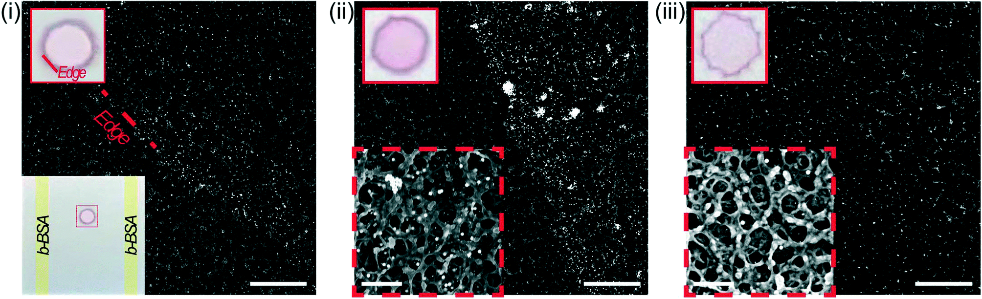 | ||
| Fig. 6 SEM images obtained at the edge of the (i) as-printed spots and after a 5 minute incubation on the (ii) benchtop orbital shaker with shear rate ∼101 s−1 or (iii) using fast CD LR with shear rate ∼103 s−1 (scale bar: 10 μm; inset scale bar: 2 μm). Dashed inset at higher magnification and solid inset of regular image illustrating spot deformation cause by fast flow. | ||
To illustrate the shear-induced effects further, we spotted Strep647 and b-BSA capture molecules to check for simultaneous desorption and reaction using the fast CD LR (∼103 s−1) and slow CD LR (∼102 s−1) at four incubation durations. The fluorescence observed between the two different CD LR conditions reaffirm the shear-dependent effects on capture molecule desorption (Fig. 7). For the fast CD LR, no further desorption is observed from 15 to 45 minutes of incubation. An increase of the Strep647 MFI after the 60 minute incubation could be attributed to the reaction with desorbed b-BSA molecules and recapture of Strep647 (Fig. 7, top, filled). Meanwhile, the largest decrease in fluorescence for the slow CD LR is observed between the 30-minute and 45 minute incubation. Meanwhile, the steady increase in fluorescence measured at the b-BSA capture molecule spots for both CD LR conditions is attributed to a slower b-BSA capture molecule desorption rate compared to the reaction rate with desorbed Strep647 (Fig. 7, bot).
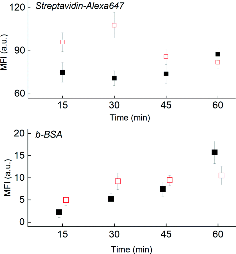 | ||
| Fig. 7 Shear rate effects on measured fluorescence for the printed Strep647 (top) and b-BSA (bot) during simultaneous desorption and cross-reaction during fast CD LR (filled, shear rate ∼103 s−1) and slow CD LR (open, shear rate ∼102 s−1). | ||
Flow considerations on antibody capture towards PoC applications
To highlight the significance of proper flow considerations during the integration of HIs to microfluidic systems, we attempted to optimize the binding of a fluorescently labeled monoclonal antibody (anti-Spike) to desorbing microarray antigen (Spike) spots printed at four different concentrations. We evaluated the mean fluorescence intensities of three different analyte concentrations (1 nM, 10 nM, and 100 nM) over time (15-, 30-, 45-, and 60 minutes) for incubation conditions using the fast CD LR (∼103 s−1) and slow CD LR (∼102 s−1). The results comparing the fluorescence intensities at different incubation conditions can be seen in Fig. 8a (Fig. S3 and S4†) and follows the same behavior as previously discussed (see Heterogeneous Immunoassay Integration and Troubleshooting).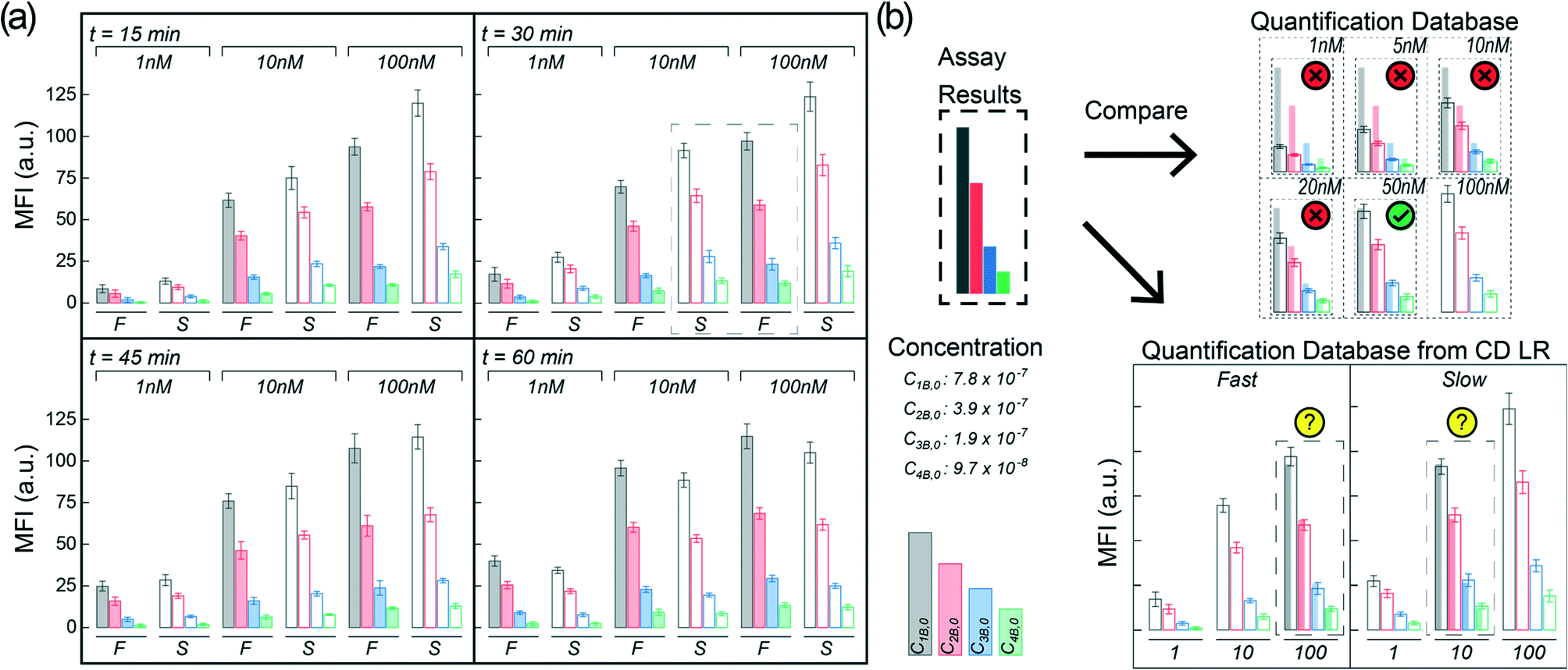 | ||
| Fig. 8 (a) Mean fluorescence intensities at each time point for fast CD LR (F) and slow CD LR (S) given different analyte concentrations. Error bars represent ± SD from n = 3 independent samples. (b) Hypothetical diagnostics using different spotted concentrations as the quantitative readout for fluorescence immunoassays comparing assay results to a hypothetical quantification database (top) and quantification database generated from different CD LR conditions at t = 30 min (bot). | ||
Briefly, the previous section indicates that incubation at higher shear rates with fast CD LR (∼103 s−1) results in an initial, rapid capture molecule desorption with no significant desorption effects seen past 15 minutes of continuous shear. Meanwhile, the fluorescence results obtained at a lower shear rate with slow CD LR (∼102 s−1) reflect a more complex phenomenon, where the fluorescence intensities depend on the capture molecule desorption rate and target molecule reaction rate.
The changes in fluorescence intensity can be attributed to desorbing capture molecules, desorbing reaction complexes, or heterogeneous reaction of target molecule binding to the capture molecules. The fluorescence intensities obtained at shorter incubation durations (Fig. 8a, t = 15 min) using slow CD LR (filled bars) were initially higher than those obtained using fast CD LR with more shear (open bars); the concentration of capture molecules on the surface of the nitrocellulose remains greater when less shear is used during incubation, resulting in more reaction complexes (and higher fluorescence intensity) compared to using more shear. However, increasing the incubation duration using the slow CD LR (t = 60 min) negatively decreases the mean fluorescence intensity due to the continuous desorption of capture molecules and reaction complexes. The increase in fluorescence intensity obtained using fast CD LR for the different spotted concentrations suggests that once desorption stops, the reaction behaves like a standard heterogenous immunoassay.
The importance of proper flow considerations is quite critical when implementing HI into a microfluidic system due to the different behaviors obtained between the fast CD LR and slow CD LR. If the assay were to be used for an analytical detection concentration near 100 nM at short incubation durations (15 minute), one would use the slow CD LR to obtain a higher mean fluorescence intensity. Conversely, if the desired detection concentration is near 1 nM, one may favor the longer, 60 minute incubation with the fast CD LR to generate a higher mean fluorescence intensity. However, selecting optimal incubation conditions becomes more challenging when expanding the desired detection concentration range to include concentrations from 1 nM through 100 nM.
For hypothetical diagnostics, the spots at different dilutions can be used in a similar way as performing serial dilutions for ELISA. The mean fluorescence intensity obtained at each spot is proportional to the total sample concentration dictated by reaction kinetics. By comparing the assay results to a quantification database, a quantitative readout can be obtained (Fig. 8b, top). However, when proper flow conditions are disregarded, different analyte concentrations can generate overlapping fluorescence profiles (Fig. 8a, t = 30 min, dotted box) making HI unsuitable for accurate diagnostics (Fig. 8b, bot). In other words, flow conditions can compound and contribute to variable test results if not carefully controlled during microfluidic assay development. Additionally, while we only observed one data group which exhibited overlapping fluorescence profiles due to different flow conditions, generating a quantification profile with more intermediate dilutions would ultimately make the HI integration for PoC diagnostics more challenging.
Conclusion
We demonstrated centrifugal disc liquid reciprocation and improper flow conditions towards heterogeneous point-of-care integration. We characterized the CD liquid reciprocation by measuring the liquid levels and simulated the process to determine the flow velocities through the reaction chamber designed for a heterogeneous immunoassay integration. The simulation was validated, and the two different liquid reciprocation profiles were tested on a heterogeneous immunoassay. For a traditional HI, the high shear rates would be extremely favorable for promoting target-capture reaction but under our circumstances, we observed the high shear rates caused loss of capture molecules available for reaction. Our results highlight the critical importance of proper flow considerations when translating immunoassays from benchtop to microfluidic systems and pave the way to investigate the importance of flow characteristics in more complex HI situations like particle-based immunoassays in which capturing sites are not fixed and particle–particle interactions exist.Conflicts of interest
There are no conflicts to declare.References
- E. P. Diamandis and T. K. Christopoulos, Immunoassay, Academic Press, 1996 Search PubMed.
- T. Mahmood and P.-C. Yang, N. Am. J. Med. Sci., 2012, 4, 429–434 CrossRef PubMed.
- J. R. Crowther, ELISA: Theory and Practice, Springer Science & Business Media, 1995 Search PubMed.
- P. Pattnaik, Appl. Biochem. Biotechnol., 2005, 126, 79–92 CrossRef CAS PubMed.
- R. B. Bird, W. E. Stewart and E. N. Lightfoot, Transport Phenomena, Wiley Global Education, 2009 Search PubMed.
- T. Gervais and K. F. Jensen, Chem. Eng. Sci., 2006, 61, 1102–1121 CrossRef CAS.
- E. L. Cussler and E. L. Cussler, Diffusion: Mass Transfer in Fluid Systems, Cambridge University Press, 2009 Search PubMed.
- H. Schlichting and K. Gersten, Boundary-Layer Theory, Springer Science & Business Media, 2003 Search PubMed.
- B. S. Lee, Y. U. Lee, H.-S. Kim, T.-H. Kim, J. Park, J.-G. Lee, J. Kim, H. Kim, W. G. Lee and Y.-K. Cho, Lab Chip, 2010, 11, 70–78 RSC.
- Y. Zhao, G. Czilwik, V. Klein, K. Mitsakakis, R. Zengerle and N. Paust, Lab Chip, 2017, 17, 1666–1677 RSC.
- S. Kim, S. Kwon, C. H. Cho and J.-K. Park, Lab Chip, 2017, 17, 702–709 RSC.
- Y. Liu, Y. Tan, Q. Fu, M. Lin, J. He, S. He, M. Yang, S. Chen and J. Zhou, Biosens. Bioelectron., 2021, 176, 112920 CrossRef CAS PubMed.
- Z. Noroozi, H. Kido, R. Peytavi, R. Nakajima-Sasaki, A. Jasinskas, M. Micic, P. L. Felgner and M. J. Madou, Rev. Sci. Instrum., 2011, 82, 064303 CrossRef PubMed.
- R. W. Glaser, Anal. Biochem., 1993, 213, 152–161 CrossRef CAS PubMed.
- M. Zimmermann, E. Delamarche, M. Wolf and P. Hunziker, Biomed. Microdevices, 2005, 7, 99–110 CrossRef CAS PubMed.
- T. M. Squires, R. J. Messinger and S. R. Manalis, Nat. Biotechnol., 2008, 26, 417–426 CrossRef CAS PubMed.
- M. Madadelahi, L. F. Acosta-Soto, S. Hosseini, S. O. Martinez-Chapa and M. J. Madou, Lab Chip, 2020, 20, 1318–1357 RSC.
- J. F. Hess, S. Zehnle, P. Juelg, T. Hutzenlaub, R. Zengerle and N. Paust, Lab Chip, 2019, 19, 3745–3770 RSC.
- A. T. Hwu, Thesis, UC Irvine, 2022 Search PubMed.
- Y. Ren and W. W.-F. Leung, Comput. Fluids, 2013, 79, 150–166 CrossRef.
- A. Ducci and W. H. Weheliye, AIChE J., 2014, 60, 3951–3968 CrossRef CAS.
Footnotes |
| † Electronic supplementary information (ESI) available. See DOI: https://doi.org/10.1039/d2lc00213b |
| ‡ Authors contributed equally to this work. |
| This journal is © The Royal Society of Chemistry 2022 |