
 Open Access Article
 This Open Access Article is licensed under a Creative Commons Attribution-Non Commercial 3.0 Unported Licence
Engineering a deformation-free plastic spiral inertial microfluidic system for CHO cell clarification in biomanufacturing†
Hyungkook
Jeon
 a,
Taehong
Kwon
a,
Junghyo
Yoon
a and
Jongyoon
Han
*abc
a,
Taehong
Kwon
a,
Junghyo
Yoon
a and
Jongyoon
Han
*abc
aResearch Laboratory of Electronics, Massachusetts Institute of Technology (MIT), Cambridge, MA 02139, USA. E-mail: jyhan@mit.edu
bDepartment of Electrical Engineering and Computer Science, Massachusetts Institute of Technology (MIT), Cambridge, MA 02139, USA
cDepartment of Biological Engineering, Massachusetts Institute of Technology (MIT), Cambridge, MA 02139, USA
First published on 14th December 2021
Abstract
Inertial microfluidics has enabled many impactful high throughput applications. However, devices fabricated in soft elastomer (i.e., polydimethylsiloxane (PDMS)) suffer reliability issues due to significant deformation generated by the high pressure and flow rates in inertial microfluidics. In this paper, we demonstrated deformation-free and mass-producible plastic spiral inertial microfluidic devices for high-throughput cell separation applications. The design of deformable PDMS spiral devices was translated to their plastic version by compensating for the channel deformation in the PDMS devices, analyzed by numerical simulation and confocal imaging methods. The developed plastic spiral devices showed similar performance to their original PDMS devices for blood separation and Chinese hamster ovary (CHO) cell retention. Furthermore, using a multiplexed plastic spiral unit containing 100 spirals, we successfully demonstrated ultra-high-throughput cell clarification (at a processing rate of 1 L min−1) with a high cell-clarification efficiency of ∼99% (at the cell density changing from ∼2 to ∼10 × 106 cells mL−1). Benefitting from the continuous and clogging-free separation with an industry-level throughput, the cell clarification device could be a critical breakthrough for the production of therapeutic biologics such as antibodies or vaccines, impacting biomanufacturing in general.
1. Introduction
The COVID-19 pandemic accelerated the growth of the biomanufacturing industry and highlighted the importance of vaccines and therapeutic proteins (e.g., monoclonal antibodies). However, improving biomanufacturing efficiency is still a critical industrial challenge to meet the ever-increasing demand for biologics.1–3 Since therapeutic proteins are secreted from engineered host cells, their production (harvesting) requires the separation of the secreted proteins and cells in large-volume bioreactors. Tangential flow filtration using a hollow fiber membrane is the most widely used method for cell retention and harvest of therapeutic proteins. However, membrane-based filtration has critical issues with fouling/clogging, the need for frequent filter replacement, and low product recovery due to nonspecific binding to the membrane surface.4–7With the advantages of label-free, passive, continuous, and high-throughput operation, inertial microfluidics has drawn much attention during the last decade.8–13 Many spiral inertial microfluidic devices have been developed and successfully utilized to separate and concentrate bio-samples, including leukocytes,14–17 circulating tumor cells,18–22 mesenchymal stem cells,23 bacteria,24 and viruses.24,25 Although inertial microfluidic devices support much higher flow rates (>1 mL min−1 per channel) than conventional microfluidic devices, it is still challenging to meet the throughput typically required in the biomanufacturing industry, where bioreactors can be as large as 1000 L.1 To meet this requirement, Warkiani et al.26 developed a multiplexed device by stacking multiple polydimethylsiloxane (PDMS) spiral devices and successfully demonstrated high-throughput and membrane-less cell filtration (up to 500 mL min−1). Although the study showed the potential to apply microfluidic systems in large-scale industrial processes, due to the labor-intensive fabrication process and inherent channel deformation, the use of multiplexed PDMS devices is still limited to proof-of-concept laboratory experiments.
The soft-lithographic technique with PDMS is the most common method to fabricate microfluidic devices due to its many advantages, including 1) rapid prototyping, 2) low production cost, 3) biocompatibility, and 4) excellent optical transparency. The fabrication process itself is straightforward but requires time-consuming and labor-intensive steps.27,28 More importantly, channels and structures in the PDMS device can be deformed from the original shape and dimensions by the hydraulic pressure when infusing fluid into the device. Also, the mechanical properties of PDMS vary depending on the PDMS curing conditions,28–34 which directly affects the behavior of the channel deformation and leads to unreliable device performance. Even though many microfluidic technologies have been translated to the commercial marketplace based on PDMS,35,36 inertial microfluidic devices are especially vulnerable because of the high pressure and high flow rate needed, potentially affecting inertial focusing behavior unpredictably.11,28 For real-world applications, the fabrication of multiplexed spiral devices must be mass-producible and standardizable by providing reliable device performance without channel deformation.
In this paper, we engineered a mass-producible, plastic spiral inertial microfluidic system to overcome the limitations of conventional PDMS devices. We demonstrated that the channel deformation significantly affects the device performance in PDMS devices by visualizing particle trajectories and deformation profiles. Based on channel deformation analysis aided by numerical simulation and confocal imaging, the empirically optimized design for PDMS devices for blood separation and Chinese hamster ovary (CHO) cell retention was translated to their plastic equivalents, which had similar performance to the original deformable PDMS devices. Furthermore, using a multiplexed plastic unit fabricated by a simple stacking method, we successfully demonstrated continuous, clogging-free, and ultra-high-throughput (at a processing rate of 1 L min−1) cell clarification with a high cell-clarification efficiency, which can meet the throughput required for biomanufacturing applications.
2. Experimental section
2.1. Device fabrication
The PDMS spiral devices were fabricated by standard soft-lithographic techniques.16,25,37,38 A 3D CAD software program (SolidWorks 2020) was used to design the spiral devices having specific channel dimensions, and the designed spiral devices were imprinted on aluminum molds via a micro-milling process (Whits Technologies, Singapore) for PDMS casting. Mixed and degassed PDMS (10![[thin space (1/6-em)]](https://www.rsc.org/images/entities/char_2009.gif) :1 mixture of base and curing agent of Sylgard 184, Dow Corning Inc., USA) was used to cast the PDMS replica from the aluminum molds, followed by curing on the hot plate for ∼7 min at 180 °C. For fluidic access, inlet and outlet holes were made on the PDMS replica using disposable biopsy punches (Integra Miltex), and then it was irreversibly bonded to a glass slide using a plasma machine (Femto Science, Korea). As an optional step, the assembled PDMS device was placed in a 60 °C oven for ∼1 h to stabilize the bonding.
:1 mixture of base and curing agent of Sylgard 184, Dow Corning Inc., USA) was used to cast the PDMS replica from the aluminum molds, followed by curing on the hot plate for ∼7 min at 180 °C. For fluidic access, inlet and outlet holes were made on the PDMS replica using disposable biopsy punches (Integra Miltex), and then it was irreversibly bonded to a glass slide using a plasma machine (Femto Science, Korea). As an optional step, the assembled PDMS device was placed in a 60 °C oven for ∼1 h to stabilize the bonding.
The plastic spiral devices were fabricated by the standard injection molding method. Similar to the PDMS spiral device, the plastic spiral devices were designed with specific channel dimensions by the 3D CAD software (SolidWorks 2020). For injection molding of the plastic spiral devices, top (flat surface w/ or w/o the protruded connection ports) and bottom (channel side) master molds were fabricated via a micro-milling process (RnD Factory, South Korea) and duralumin was used for the mold material. The top master mold having the protruded connection ports was used to fabricate the plastic device for tubing connection as the top layer of the stacked device (or when a not-stacked single device is used alone), and the top master mold without the connection ports was used to fabricate the plastic device for the device stacking while the same bottom master mold was used for both connection types to imprint the same spiral channel. Polycarbonate resin was used for the plastic device material. For sealing the channel side of the plastic spiral device, double-sided adhesive film (IS-00726-01, RnD Factory, South Korea) was used. Processes of cutting the film to have the same size as the plastic device and making holes on the film for fluidic access were conducted precisely and automatically by a film cutting machine (GSP32-32, Gu Sung Machine, South Korea). The manufactured plastic spiral device was bonded to the double-sided adhesive film via a manual film attachment process using an alignment-guide plate in clean-room space (see Video S1† for the detailed device-production and film-attachment processes). To fabricate the multiplexed spiral device, a plastic device having protruded connection ports was used for the top layer of the stacked device for tubing connection, and plastic devices without connection ports were used for the device stacking. For precise and fast alignment for stacking, an aluminum pin holder was fabricated via a standard milling process (see Video S2† for the detailed device-stacking process). To prevent fluidic leakage, the multiplexed spiral device was clamped by the top and bottom stainless steel plates (5 mm thickness) with bolted joints.
Dimensions of the plastic devices were determined based on the deformation analysis via numerical simulation and confocal imaging. In the case of the multi-dimensional double spiral (MDDS) device, the first and second spiral channels of its plastic version were designed to have 50%- and 25%-increased heights from the original heights, respectively (Fig. 3a). The increased portion of the first channel height was determined based on the average (67.8%) and minimum (42.3%) channel deformation ratios at the first channel from the numerical simulation to achieve sufficient inertial focusing. The increased portion of the second channel height was determined by slightly increasing the average channel deformation ratio (15.5%) from the numerical simulation to compensate for the arc-shaped deformation of its trapezoidal cross-section. In the case of the spiral device for CHO cell retention, its plastic version was designed to have a 50%-increased channel height from the original height of its PDMS version and a decreased loop number (Fig. 3e). From the trajectory of CHO cells in the original PDMS device (Fig. S6†), we found that the first 4 loops are enough for their focusing into the inner-wall side, so we reduced the number of loops to avoid unnecessary pressure loss and determine the increased portion of the channel height based on the average channel deformation ratio of the first four-loop channel region (53.4%) rather than the entire channel region (36.3%).
2.2. Device characterization and bio-sample processing
For observation of particle trajectories in the MDDS device, fluorescent polystyrene particles having diameters of 6.0 μm (18141-2, Polysciences, Inc., USA) and 10.0 μm (F8834, Invitrogen, USA) with dilution in deionized water were used to mimic red blood cells (RBCs) and white blood cells (WBCs), respectively. For blood separation tests in the MDDS device, healthy peripheral blood samples were purchased from Research Blood Components, LLC (Boston, MA, USA) and used under a specific dilution condition of 1:500 (50 μL in 25 mL of 1× phosphate-buffered saline without calcium and magnesium (PBS, Corning, USA)).
CHO cell lines were obtained from companies and maintained in spinner flasks (working volume of 250 mL, 4500–500, Corning, USA) in an incubator. For a larger volume (e.g., 1 L), the cell culture in different flasks was combined. Cell density and viability were checked by an automated cell culture analyzer (FLEX2, NovaBiomedical, USA) before spiral operation.
A syringe pump (PHD ULTRA, Harvard Apparatus, USA and Fusion 200, Chemyx, USA) was used to regulate the flow rate, and an inverted fluorescence microscope (IX51, Olympus Inc., USA) and a CCD camera (Sensicam QE, PCO, Germany) were used to observe the trajectories of the fluorescent particles and collect images from the device. To observe trajectories of blood cells and CHO cells having no fluorescence, a high-speed camera (Phantom v9.1, Vision Research Inc., USA) was used at a specific sample rate of 100 pictures per second (pps).
For the high-throughput cell clarification platform, two centrifugal pumps (PLD-i100SU, Levitronix, USA) were used in series. The rpm condition of one pump was controlled by a console system (LCO-i100, Levitronix, USA) based on the input flow rate measured by an external flow sensor (LFS-06SU, Levitronix, USA) placed between the pump and the device, while the rpm condition of the other pump was pre-set at a specific rpm rate. A spinner flask having a capacity of 1 L (Corning, USA) was used for the cell-retention chamber, and a stirrer (SS2I, Corning, USA) was used at 60 rpm to mix the cell sample continuously. A flow meter/regulator (6A0109BV-WA, Dakota Instruments, Inc., USA) was used to manipulate flow split between the two outlets (15:1 = the inner-outlet flow:the outer-outlet flow) from the multi-layer-stacked device, which was placed between the outer-wall side outlet and the harvest (cell-clarification) bottle; only the flow rate of the outer-wall side output was manipulated, and the flow rate of the inner-wall side output was determined as (the input flow rate minus the flow rate of the outer-wall side output).
2.3. Numerical simulation
COMSOL Multiphysics 5.5 was used to numerically analyze the channel deformation in the two PDMS spiral devices, the MDDS device for blood separation and the spiral device for CHO cell retention. For the geometry in the numerical simulation, the 3D CAD file of each spiral channel was imported with minor modifications to remove unnecessary structures for the simulation, and a PDMS block structure was added to form the PDMS device engraved with the spiral channel. As a result, two domains were generated; one is for the spiral channel, and the other is for the PDMS block excluding the spiral channel region. Default properties of water were applied to the domain of the spiral channel, and mechanical properties of PDMS (density of 970 kg m−3, Poisson's ratio of 0.49, and variable Young's modulus conditions) were applied to the domain of the PDMS block. In the numerical simulation, three modules (moving mesh, laminar flow, and solid mechanics) were included. Using the laminar flow module, normal inflow velocity condition and zero pressure condition were applied to the inlet and outlet surfaces, respectively. In the solid mechanics module, the pressure generated by the fluidic flow in the laminar flow module was applied as a boundary load condition to the interfaces between the spiral channel and the PDMS block, and a fixed constraint condition was applied to the bottom surface of the PDMS block. In the moving mesh module, free deformation condition was applied to the domain of the spiral channel, and the displacement by the boundary load in the solid mechanics module was applied as the prescribed mesh displacement condition to the interfaces between the spiral channel and the PDMS block. As a result, the domain of the spiral channel can be deformed according to the analysis in the solid mechanics module so that the laminar flow module and the solid mechanics module can be fully coupled through the moving mesh module. In the numerical simulation, the channel deformation was analyzed by altering three parameters which are 1) input flow rate, 2) Young's modulus of PDMS, and 3) PDMS thickness, by using the parametric sweep method.2.4. Confocal imaging
An inverted confocal fluorescence microscope (IX83, Olympus, Japan) was used to provide 3D imaging of the deforming channels in the PDMS spiral channels.33 Under infusion of a diluted fluorescein solution as a fluorescent dye, confocal images of the channel cross-section on each loop of the spiral devices were acquired under various flow rate conditions. For the PDMS MDDS device for blood separation, Z-stacks (range: 250 μm and step size: 5 μm) were obtained by using an objective lens of 10×, which can fully cover the channel cross-section even under its deformation. For the spiral device for CHO cell retention, Z-stacks (range: 450 μm and step size: 10 μm) were obtained by using an objective lens of 4×, which can fully cover the channel cross-section even under its deformation. Cross-section images were extracted from the obtained Z-stacks by using Image-J. As shown in Fig. 2f, the cross-section images were converted to binary images to determine the outline, and then profiles of channel heights were obtained from the channel outline as a difference between the maximum z-value and the minimum z-value, by using our own MATLAB code. In the conversion process to a binary image, the luminance threshold was determined based on the known step size of Z-stacks and the cross-section image of the no-flow condition where the channel has the originally-designed dimensions without deformation.2.5. Downstream analysis
To determine the blood separation efficiency of the MDDS device, input and output samples were collected and analyzed using a flow cytometer (Accuri C6, BD Biosciences, USA). The following antibodies were used for blood cell classification: fluorescein isothiocyanate (FITC)-conjugated CD45 monoclonal antibody (positive for all leukocytes) and allophycocyanin (APC)-conjugated CD66b monoclonal antibody (positive for PMNs); all the antibodies were purchased from eBioscience. Because there is no efficient surface marker to determine MNLs which are composed of various sub-types, the number of MNLs was calculated as CD45-positive but CD66b-negative cells.The CHO cell culture samples were analyzed using an automated cell culture analyzer (FLEX2, NovaBiomedical, USA). The analyzer spreads the cells in a flow and analyzes cell density (million cells per mL) and viability (trypan blue exclusion test) statistically from captured images.
3. Results
3.1. Overview of the plastic spiral inertial microfluidic device
Fabrication of the PDMS device requires time-consuming and labor-intensive steps, especially in the PDMS casting step, which includes 1) mixing the pre-polymer and cross-linker, 2) degassing the mixture, 3) curing the PDMS replica, and 4) making holes for fluidic access (Fig. 1a).27,28 One can make a multiplexed device by stacking multiple PDMS devices for high-throughput applications, but it requires time-consuming layer-by-layer manual assembly and bonding. It is challenging to consistently control the thickness and flatness of each device layer and align the location of the holes for fluidic access. Another limitation of the PDMS device is the pressure-induced channel deformation which changes the original channel dimensions, resulting in unreliable device performance. As shown in Fig. 1b, the channel deformation is not consistent but location-dependent according to the decreasing pressure from the inlet to the outlet. Furthermore, the channel deformation is affected by experimental conditions (e.g., flow rate and channel dimensions) as well as Young's modulus of PDMS, which varies from 0.5 to 4.0 MPa depending on the PDMS curing conditions (i.e., curing temperature and time, and mixing ratio of the pre-polymer and cross-linker).28–34 In particular, inertial microfluidics requires a high flow rate (order of mL min−1) with a finite Reynolds number (Re = ρUDH/μ, where ρ, μ, and U represent the density, dynamic viscosity, and velocity of the fluid, respectively, and DH represents the hydraulic diameter of the channel),11,28 resulting in the significant pressure-induced channel deformation. Because the particle focusing behavior in the inertial microfluidic devices is strongly dependent on the ratio of particle size to channel (cross-sectional) dimensions, the channel deformation directly affects device performance.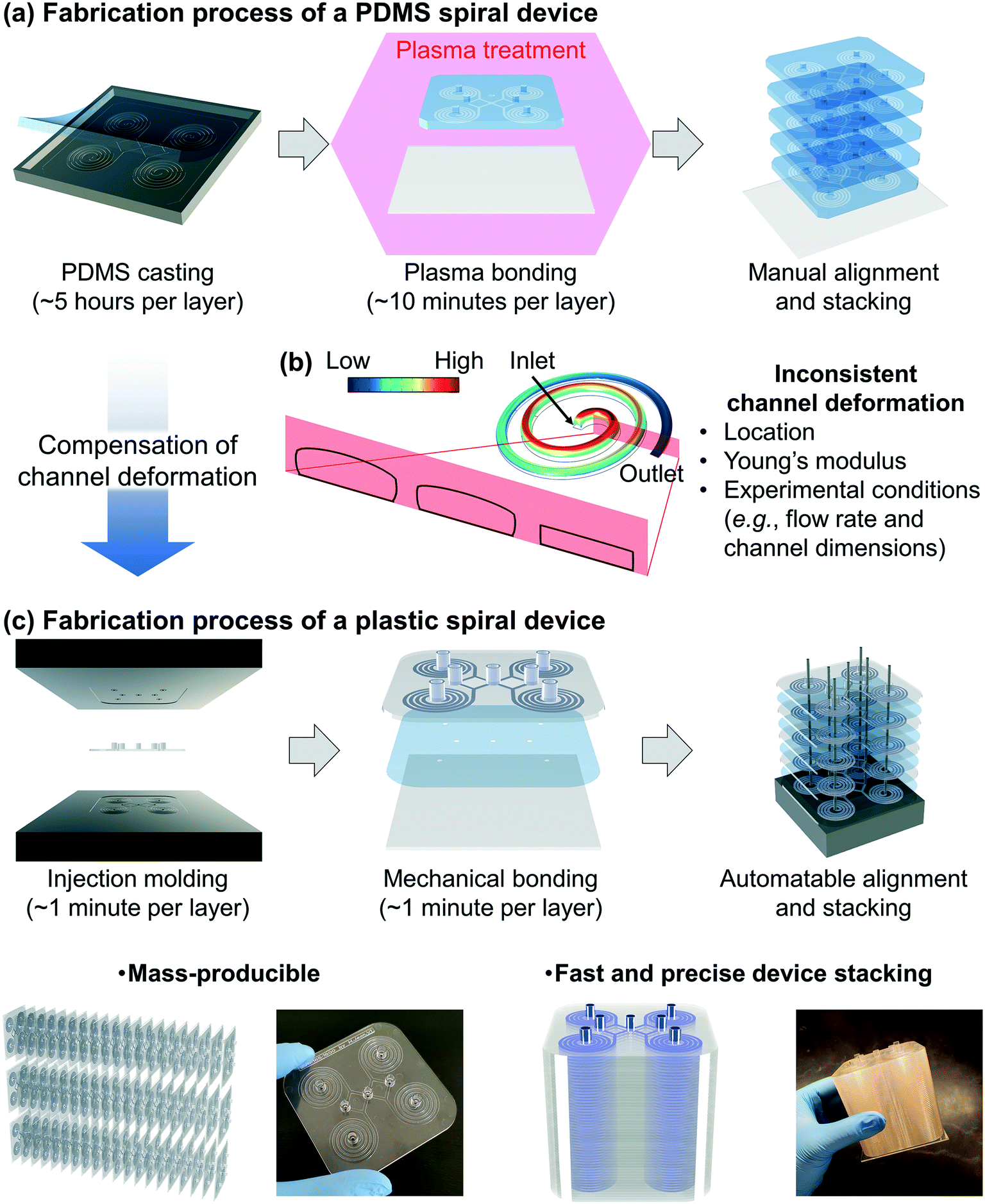 | ||
| Fig. 1 Development of a mass-producible and deformation-free plastic spiral inertial microfluidic device. (a) A schematic diagram representing the fabrication process of the conventional polydimethylsiloxane (PDMS) spiral device and its stacking process for high-throughput application. (b) A schematic diagram representing the channel deformation in the PDMS spiral device and its effects on the device operation and performance; the color represents the relative channel deformation. (c) A schematic diagram representing the fabrication process of the plastic device and its key advantages; the plastic spiral device was designed by compensating for the channel deformation in the PDMS spiral device. | ||
To overcome the limitations in the PDMS device, we developed deformation-free and mass-producible plastic inertial microfluidic systems (Fig. 1c), where we previously optimized PDMS inertial devices for blood separation39 and Chinese hamster ovary (CHO) cell retention,40–42 respectively. In inertial microfluidics, the channel dimension (especially the height of the channel) is a critical parameter determining the particle focusing in the channel by affecting particle-experienced forces (lift and Dean drag forces). Therefore, to achieve desired device performance, it is critical to compensate for the channel deformation and assign actual channel dimensions when converting a PDMS device design to its plastic version. To identify the actual channel dimensions when the original PDMS spiral inertial devices operate under their optimal (flow rate) conditions, we analyzed the channel deformation by both numerical simulation and confocal imaging. Based on the analysis, the dimensions of the equivalent plastic devices were determined and manufactured via a conventional injection molding process, which provides inexpensive (∼1 US dollar per device) and fast (∼1 minute per device, compared to ∼5 hours for a single PDMS device) device production, with more robust mechanical properties (∼1 GPa Young's modulus) compared to the PDMS device (∼1 MPa) (Fig. 1aversusFig. 1c).28 As shown in Fig. 1c, we can obtain a ready-to-use plastic device via a simple film attachment process for sealing the channel using a double-sided adhesive film for mechanical bonding between the device and a bottom substrate. This plastic device is deformation-free (reliable particle manipulation) and mass-producible (disposable). The multiplexed plastic device can be assembled by simple stacking, enabling ultra-high-throughput industrial applications.
3.2. Analysis of channel deformation in the PDMS spiral devices
The first spiral device translated to the plastic device is the multi-dimensional double spiral (MDDS) device designed for leukocyte isolation from the blood sample.39 The MDDS device consists of sequentially connected two spiral channels having different dimensions to integrate two different functions, sample focusing and separation, in a single device without sheath flow (Fig. 2a). First, to see the effects of the channel deformation on the device performance, we designed and tested the plastic MDDS device which has the same dimensions as the original PDMS device. For device characterization, particles with diameters of 6 (green) and 10 μm (red) were used to mimic the movement of RBCs and WBCs, respectively. Fig. 2b and c show the particle trajectories at the outlet bifurcation region (denoted by the red box in Fig. 2a) in the original PDMS MDDS device and the plastic MDDS device, respectively, under the same flow rate condition of 9.2 mL min−1 (2.3 mL min−1 ×4 for the quad-version); 2.3 mL min−1 is the optimized flow rate condition of the original PDMS MDDS device for blood separation as well as particle separation.39 The results clearly show that the plastic MDDS device has a smaller dimension than the actual dimension of the original PDMS device that is deformed under pressure. Particles experienced a higher lift force so that the trajectory of 6 μm particles was shifted closer to the inner wall compared to the PDMS device. In contrast, 10 μm particles kept their trajectory which was already near the inner wall (Fig. 2bversusFig. 2c). Therefore, the optimal plastic device needs to have the actual deformed channel dimensions of the PDMS device.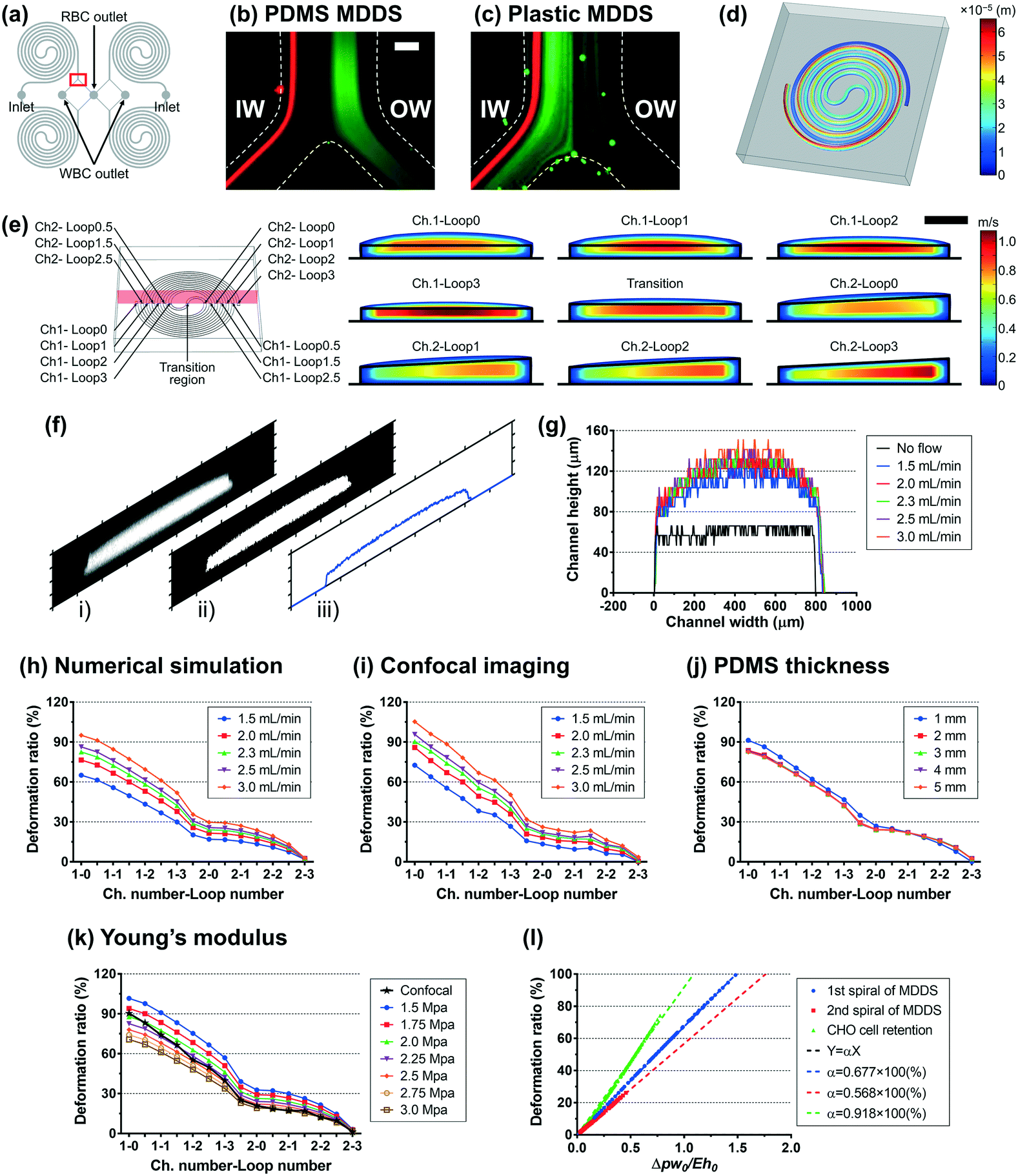 | ||
| Fig. 2 Analysis of channel deformation in the PDMS multi-dimensional double spiral (MDDS) device for blood separation based on numerical simulation and confocal imaging methods. (a) Channel configuration of the quad-version MDDS device for blood separation. Particle trajectories in (b) the original PDMS MDDS device and (c) the plastic MDDS device having the same channel dimensions under the same flow rate condition of 9.2 mL min−1 (= 2.3 mL min−1 ×4 for the quad-version); particles having diameters of 6 (green) and 10 μm (red) were used to mimic the movement of RBCs and WBCs, respectively (scale bar: 200 μm). (d) A 3D profile of the overall channel deformation; for clearer visualization, the 3D deformation profile was amplified with a scale factor of 25. (e) The channel deformation at each loop in a cross-sectional view; the solid black line represents the initial channel outline (scale bar: 200 μm). (f) Conversion and analysis process of the confocal cross-sectional image at the inlet region in the device using a MATLAB code. (g) Channel height profiles obtained from (f) depending on the input flow rate. Profiles of the deformation ratio at each loop under various input flow rate conditions, obtained by (h) numerical simulation and (i) confocal imaging, where the deformation ratio was defined by ‘(change of the cross-section area)/(original cross-sectional area)’. (j) Profiles of the deformation ratio at each loop under various PDMS thickness conditions, obtained by numerical simulation. (k) Profiles of the deformation ratio at each loop under various Young's modulus conditions, obtained by numerical simulation and confocal imaging. (l) The average deformation ratio of the MDDS and CHO cell retention devices depending on the dimensionless number (Δpw0/Eh0, where Δp represents the pressure drop applied to the channel, w0 and h0 denote the original channel width and height, respectively, and E means Young's modulus); the average deformation ratio over the entire channel region was used for Δh/h0 while the median pressure value ((pinlet + poutlet)/2) was used for Δp instead of the average pressure, which was obtained by numerical simulation. In (l), the input flow rate and Young's modulus of PDMS were manipulated to control the dimensionless number (Δpw0/Eh0). For the MDDS device for blood separation, all the combinations of 12 flow rate conditions (from 0.25 to 3.0 mL min−1 with a step size of 0.25 mL min−1) and 7 Young's modulus conditions (from 1.5 to 3.0 MPa with a step size of 0.25 MPa) were tested, resulting in a total of 84 conditions. Because the MDDS device is composed of two spiral channels having different dimensions, the first and second spiral channels were analyzed separately. For the CHO cell retention device, all the combinations of 20 flow rate conditions (from 1.0 to 20.0 mL min−1 with a step size of 1.0 mL min−1) and 7 Young's modulus conditions (from 1.5 to 3.0 MPa with a step size of 0.25 MPa) were tested, resulting in a total of 140 conditions. All the numerical simulation results were obtained under default parametric conditions of the input flow rate (2.3 mL min−1), Young's modulus (2.25 MPa), and PDMS thickness (5 mm) except when the parameter becomes a variable. MDDS device, multi-dimensional double spiral device; IW, inner wall; OW, outer wall. | ||
Numerical simulation was performed to analyze the channel deformation affected by three experimental parameters, which are 1) input flow rate (default: 2.3 mL min−1), 2) Young's modulus of PDMS (default: 2.25 MPa), and 3) PDMS thickness (default: 5 mm). Fig. 2d shows a 3D profile of the channel deformation in the PDMS MDDS device, and Fig. 2e shows the channel deformation at each loop in a cross-sectional view (the solid black line represents the initial channel outline) under the default conditions. As we expected, the channel deformation was highest (∼100% of deformation ratio from the initial dimension) near the inlet, and decreased along the channel. Fig. 2h shows the profiles of the deformation ratio at each loop depending on the input flow rate. Due to the increased pressure drop, the deformation ratios for the entire channel regions increase as the input flow rate increases. In particular, at each input flow rate condition, due to the smaller dimension in the original channel design, a higher pressure drop is generated in the first spiral channel compared to the second spiral channel, resulting in a higher slope of the decrease in the deformation ratio (total pressure drop in the entire channel including the S-shaped transition region: ∼2.35 × 10⁵ Pa, pressure drops in the first and the second channels: ∼1.32 and ∼0.92 × 10⁵ Pa, respectively, under the default parameter conditions). We also analyzed the channel deformation depending on the PDMS layer thickness, and the results showed that the effect of the PDMS thickness is negligible unless it becomes comparable (<1 mm) to the channel height (Fig. 2j). Fig. 2k shows the effect of Young's modulus on the channel deformation. Young's modulus was altered in the range of 1.5 to 3.0 MPa with a step size of 0.25 MPa. The results clearly showed that the deformation ratio significantly decreases as the modulus increases (up to 40% difference between 1.5 and 3.0 MPa conditions at the inlet region with the highest deformation).
To validate the numerical simulation results, we measured the actual deformation of the channel cross-section by confocal microscopy.33 As shown in Fig. 2f, our own MATLAB code was used to analyze the captured confocal images of cross-sections; i) an original captured confocal image was converted to ii) a binary image and then converted to iii) a height profile of the cross-section (details are described in the Experimental section). As shown in Fig. 2g, the confocal imaging results showed the channel deformation from its original shape (represented by the solid black line) and the increase of the deformation with the larger input flow rate. Fig. 2i shows the profiles of the deformation ratio at each loop at various input flow rate values. The profiles match the results from the numerical simulation well (Fig. 2h), in terms of the location-dependent deformation as well as the effect of the input flow rate. The height profiles at each loop depending on the input flow rate are described in Fig. S1.† We compared the profiles of the deformation ratio obtained from the numerical simulation and confocal imaging methods and found that the profile at 2.25 MPa of Young's modulus showed the best match with the profile from the confocal imaging at the optimal flow rate of 2.3 mL min−1. From this, we can quantify the deformation ratios of the first and second spiral channels in the PDMS MDDS device used in this study as 67.8% and 15.5%, respectively, more accurately than one can measure from confocal imaging alone.
The second spiral device translated to the plastic device is the spiral device for CHO cell retention. The device has a conventional single spiral configuration but has a specific dimension that was optimized for retention (or removal) of CHO cells in a size range of 10–20 μm (Fig. S2a†). The device has a trapezoidal cross-section with 1500 μm in width and 180 and 110 μm in height for the inner and outer-wall sides, respectively, with eight loops.40–42 Using the same approach as for the MDDS device, the channel deformation in the CHO cell retention device was analyzed by numerical simulation and confocal imaging methods. The detailed analysis is found in Fig. S2 and S3,† respectively. Profiles of the channel deformation in the CHO cell retention device were in line with the results from the earlier plastic MDDS device optimization. Interestingly, we found that a Young's modulus of 2.25 MPa provides the best match between confocal imaging and numerical simulation as well (Fig. S2e†), verifying a similar PDMS curing condition used in our laboratory. From the numerical simulation result at the Young's modulus of 2.25 MPa and the optimal flow rate of 10.0 mL min−1, the average deformation ratio of the CHO cell retention device was 36.3%.
Gervais et al. developed a scaling relation to analyze the channel deformation in the PDMS microfluidic device.33 Under the assumption of the infinite medium condition where the PDMS medium is thick enough to make all strains vanish very far from the deforming region, the relationship between the channel deformation and applied pressure can be obtained from Hooke's law, as follows:
 | (1) |
 | (2) |
To obtain the dimensionless number (Δpw0/Eh0), one can calculate the hydraulic resistance of the channel and pressure drop theoretically, using the channel dimensions and the applied flow rate. Fig. S4† shows the dependency between the theoretically calculated dimensionless number (Δpw0/Eh0) and the deformation ratio obtained from the numerical analysis. Because the theoretically calculated pressure drop does not reflect the channel deformation, the deformation ratio has a nonlinear dependency on the dimensionless number (Δpw0/Eh0); the theoretically calculated pressure drop has a higher value than its actual value under the channel deformation. Due to this, accurate assessment of the channel deformation would require a complete numerical analysis as demonstrated in this work, while the theoretically calculated dimensionless number (Δpw0/Eh0) could provide a rough guide on the importance of channel deformation in a given experimental condition.
3.3. Cell manipulation performance of the plastic spiral devices
Based on the deformation analysis, we translated the two original PDMS spiral devices for blood separation and CHO cell retention to their plastic version with modified dimensions. The average deformation ratio of the channel was considered in determining the modified dimensions, and slight adjustment was additionally applied considering the shape change of the channel cross-section and the particle behavior in the original PDMS devices (see the Experimental section for details). The plastic device was manufactured by the standard injection molding method and then bonded to a flat plastic substrate using a double-sided adhesive film; the detailed fabrication process of the plastic device is described in the Experimental section and Video S1.†In the case of the plastic version of the MDDS device, the first and second spiral channels were designed to have a 50%- and 25%-increased height from the design of the original PDMS device, respectively (Fig. 3a). Fig. 3b shows a 3D profile of the channel deformation in the plastic MDDS device at a flow rate of 1.5 mL min−1, obtained by numerical simulation. Polycarbonate resin used for the plastic device has a Young's modulus of 2 GPa.28,43 The result clearly shows that the channel deformation in the plastic MDDS device is negligible; the maximum channel deformation was ∼58.6 nm, which is less than 0.1% of the lowest channel height, 90 μm (Fig. 3b). Fig. 3c shows the trajectories of 6 μm and 10 μm particles (mimicking RBCs and WBCs, respectively) in the plastic device under the optimized flow rate condition of 6 mL min−1 (1.5 mL min−1 for each spiral); trajectories of particles and blood cells under various flow rate conditions are represented in Fig. S5.† Similar to the original PDMS device,39 both 6 and 10 μm particles were well focused into the inner-wall side in the first spiral channel and clearly separated in the second spiral channel. Fig. 3d shows the blood separation performance of the plastic device depending on the input flow rate. From the results, we found that >90% of red blood cells (RBCs) were removed, while >80% of white blood cells (WBCs) were recovered at the optimized flow rate condition of 6 mL min−1 (initial sample: 500× diluted blood). Compared with the original PDMS MDDS device (>90% RBC removal and >90% WBC recovery), the RBC removal rate is similar, but the WBC recovery efficiency is slightly lower. In addition, the results showed that the PMN (polymorphonuclear leukocyte) recovery was better than the MNL (mononuclear leukocyte) recovery due to its larger size (PMN: 10–12 μm versus MNL: 7–10 μm), which is also in line with the results from the original PDMS device.39
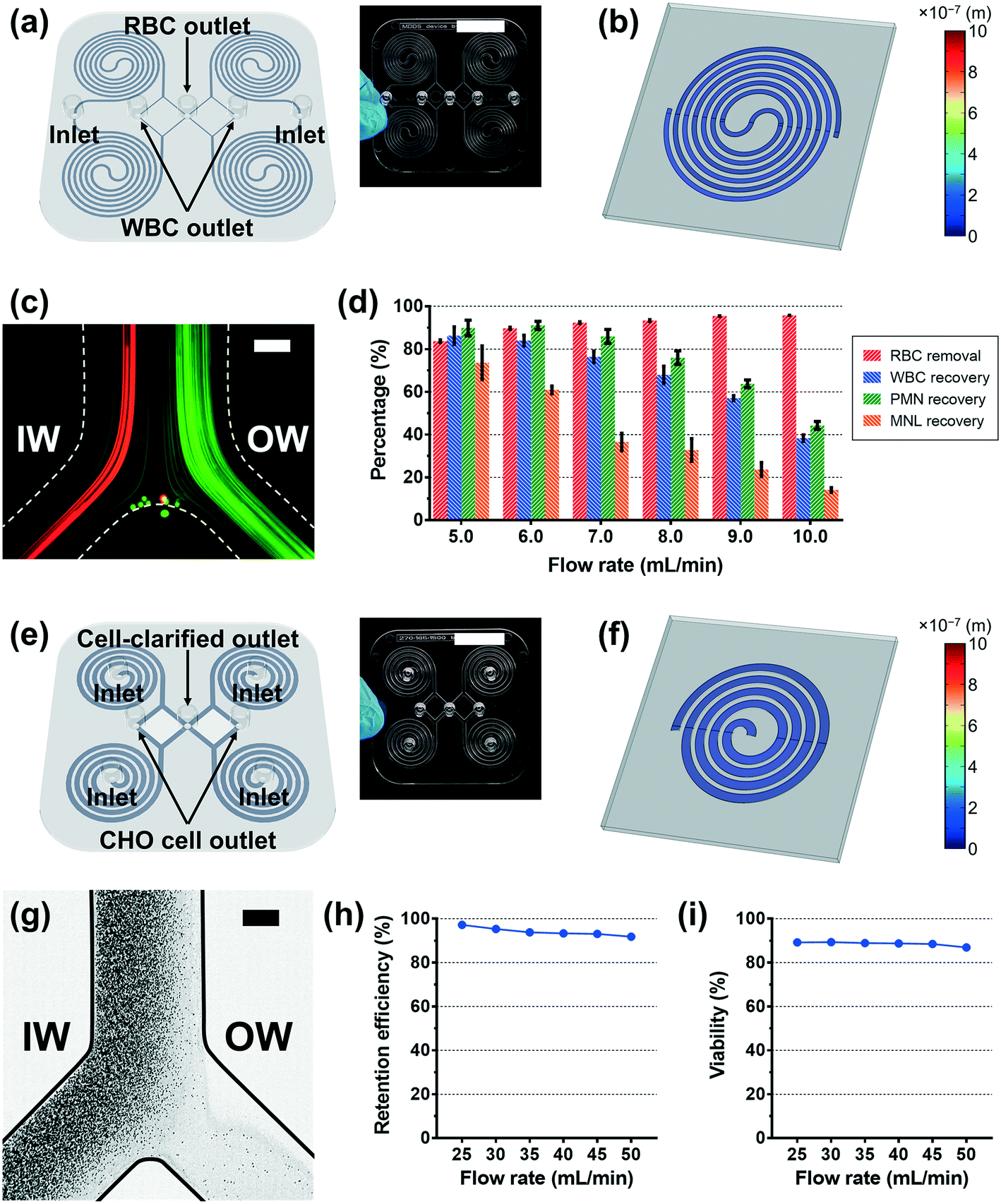 | ||
| Fig. 3 Cell manipulation performance of the plastic spiral devices. (a) A 3D CAD image and a photo (inset, scale bar: 25 mm) of the plastic MDDS device for blood separation (the first channel: rectangular cross-section with 800 μm in width and 90 μm in height with three loops, the second channel: trapezoidal cross-section with 800 μm in width and 100 and 150 μm in height for the inner- and outer-wall sides, respectively, with three loops). (b) A 3D profile of the channel deformation in the plastic MDDS device, obtained by numerical simulation at a flow rate of 1.5 mL min−1. (c) Particle trajectories at the outlet bifurcation region in the plastic MDDS device at a flow rate of 6 mL min−1 (1.5 mL min−1 for each spiral); particles having diameters of 6 (green) and 10 μm (red) were used to mimic the movement of RBCs and WBCs, respectively (scale bar: 200 μm). (d) RBC removal and WBC recovery efficiencies in the inner-wall side outputs under various flow rate conditions. In (d), 500× diluted blood was used for the input, and the values in the graph are expressed as the mean ± SD (n = 3). (e) A 3D CAD image and a photo (inset, scale bar: 25 mm) of the plastic CHO cell retention device from cell culture (trapezoidal cross-section with 1500 μm in width and 270 and 165 μm in height for the inner- and outer-wall sides, respectively). (f) A 3D profile of the channel deformation in the plastic CHO cell retention device, obtained by numerical simulation at a flow rate of 10 mL min−1. (g) Trajectory of CHO cells at the outlet bifurcation region in the plastic CHO cell retention device at a flow rate of 40 mL min−1 (10 mL min−1 for each spiral) (scale bar: 500 μm). (h) Retention efficiency of CHO cells to the inner-wall side outlet under various flow rate conditions. (i) Profiles of the cell viability of the retained cells under various flow rate conditions. In (g), (h), and (i), the input CHO cell sample has a cell density of ∼11.8 × 10⁶ cells mL−1 with ∼90% viability (n = 1). MDDS device, multi-dimensional double spiral device; IW, inner wall; OW, outer wall; RBC, red blood cell; WBC, white blood cell; PMN, polymorphonuclear leukocyte; MNL, mononuclear leukocyte; CHO cell, Chinese hamster ovary cell. | ||
In the case of the spiral device for CHO cell retention, its plastic version was designed to have a 50%-increased channel height from the original height of its PDMS version (Fig. 3e). With the modified channel dimensions, to avoid unnecessary pressure loss and increase throughput, we reduced the number of loops from eight to four. We changed the channel configuration to embed four spiral channels in parallel (see the Experimental section for details). Fig. 3f shows a 3D profile of the channel deformation in the plastic CHO cell retention device at the optimal flow rate of 10 mL min−1, obtained by numerical simulation. Similar to the plastic MDDS device, the result clearly shows that the channel deformation in the plastic CHO cell retention device is negligible; the maximum channel deformation was ∼32.6 nm, which is less than 0.02% of the average channel height, 217.5 μm (Fig. 3f). Fig. 3g shows the trajectories of CHO cells in the plastic device at a flow rate of 40 mL min−1 (10 mL min−1 for each spiral). Flow split between the inner- and outer-outlet flows was controlled by an external flow regulator to be approximately 15:1 (= the inner-outlet flow:the outer-outlet flow) to collect the cell-clarified portion from the outer-wall side outlet. As shown in Fig. 3g, we observed that the CHO cells were well focused into the inner-wall side at the outlet bifurcation region so that the cell-clarified solution was obtained from the outer-wall side outlet (input cell density: ∼11.8 × 10⁶ cells mL−1), similar to the original PDMS device (Fig. S6†). Because the plastic device (quad version) is designed to have four spiral channels in parallel, the input flow rate of 40 mL min−1 is equivalent to the optimal flow rate condition of its original single PDMS spiral version (10 mL min−1). Trajectories of the CHO cells and the cell-retention efficiency to the inner-wall side output under various flow rate conditions are represented in Fig. S7† and 3h, respectively. From the results, we found that the CHO cells can be focused well with a similar trajectory regardless of the input flow rate condition in the specific tested range of 25–50 mL min−1. This resulted in high cell-retention efficiency (up to 97%) to the inner-wall side output in the wide range of flow rate conditions. As shown in Fig. 3i, the viability of the retained cells was similar to the initial viability (∼90%), showing minimum cell damage during the separation process. In addition, using the numerical simulation, the required pressure was also analyzed and compared with the original PDMS version. The required pressure for the plastic CHO cell retention device is ∼3.36 × 10⁴ Pa at the optimal flow rate of 10 mL min−1, which is much lower than the pressure drop in its original PDMS version having eight loops (∼1.36 × 10⁵ Pa). Due to the reduced loop number in the plastic device, we can avoid a significant portion of pressure loss while maintaining cell focusing performance.
3.4. High-throughput cell-clarification using a multiplexed plastic device
As a showcase for an industrial application, we demonstrated an ultra-high-throughput (∼a few L min−1) CHO-cell clarification (extraction of the cell culture supernatant) using the plastic device, as an alternative to conventional membrane-based filtration techniques. A high-throughput multiplexed device can be easily fabricated via a simple stacking process (Video S2†). As shown in Fig. 4a, a double-sided adhesive film was used to seal the microfluidic channel layers; holes were made on the film for fluidic access between devices precisely by an automatic film cutting machine (Video S1†). A plastic device layer with protruded fluid-fitting connection ports was used as the top layer of the device stack. Both plastic devices with and without the connection ports were made by using the same bottom master mold from a commercial vendor (RnD Factory, South Korea).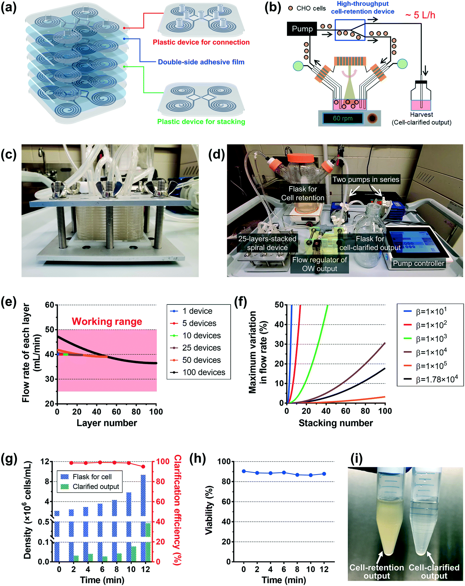 | ||
| Fig. 4 Ultra-high-throughput cell-clarification using a multiplexed plastic device. (a) A 3D schematic diagram of the device-stacking process. (b) A schematic diagram of the high-throughput cell-clarification process. (c) A photo of a 25-layer-stacked device clamped by stainless steel plates with bolted joints. (d) A photo of the high-throughput cell-clarification platform using a 25-layer-stacked device. (e) Analysis of flow rate distribution into each layer of the multi-layer-stacked devices under various stacking numbers by circuit simulation (circle) and theoretical calculation (solid line), based on the electric circuit analogy. (f) Maximum variation in flow rate (%) depending on the stacking number under various (device)-to-(connection part) resistance ratios (β = RD/RC, where RD and RC (= RIH + ROH) are hydraulic resistances of the spiral device and the (inlet-holes and outlet-holes) connection parts between layers, respectively), obtained by theoretical calculation; the solid black line represents the profile of our plastic CHO cell retention device. (g) Profiles of the cell densities in the flask of the retained CHO cells (blue bar) and the cell-clarified output (green bar) and the cell-clarification efficiency (= cell-retention efficiency, red line) (initial CHO cell density: ∼2.14 × 10⁶ cells mL−1 in ∼1 L volume, input flow rate: 1 L min−1, flow split: 15:1 = the inner-outlet flow:the outer-outlet flow, n = 1). In (g), the cell density of the cell-clarified output (green bar) does not represent the overall cell density in the harvest (cell-clarification) bottle, but the cell density of the temporary samples obtained directly from the outlet tubing. (h) Profiles of the cell viability in the flask of the retained CHO cells (n = 1). (i) A photo of the final outputs from the cell-retention flask and the harvest (cell-clarification) bottle. CHO cell, Chinese hamster ovary cell; OW, outer wall; IH, inlet holes; OH, outlet holes; D, device. | ||
Fig. 4b shows the schematic diagram of the high-throughput cell-clarification process. Here, we tested a 25-layer-stacked device (Fig. 4c), where 100 (= 25 × 4) spiral channels are combined to form a separation unit for a spinner flask with 1 L cell culture solution. We flowed the cell culture solution from the flask into the multiplexed device by a centrifugal pump(s), and the device returns the cells back into the flask while harvesting the cell-clarified supernatant to a separate bottle. Fig. 4d shows an image of the cell purification setup using the 25-layer-stacked device, which includes 100 spiral channels. To achieve a sufficient input pressure, two centrifugal pumps (PLD-i100SU, Levitronix, USA) were used in series, and their rpm rates were manipulated by a controller which is connected with a flow meter for the input flow rate. The input flow rate of 1 L min−1 (= 25 × 40 mL min−1) was generated under approximately 4000 rpm conditions for both pumps. Flow split between two outlets was controlled to be 15:1 (= the inner-outlet flow:the outer-outlet flow, harvesting rate of cell-clarified output: ∼65 mL min−1 = ∼4 L h−1) by an external flow regulator in the line of the outer-wall side outlet; the detailed operation process is described in Video S3.†
First, we examined how uniformly the whole input flow can be distributed into the individual layer of the multiplexed device. Ideally, if there is no hydraulic resistance between layers, the input fluid can be distributed into the individual layer evenly. However, we made inlet and outlet holes on the device for fluidic access across layers, which causes hydraulic resistance between layers in the multiplexed device. As a result, due to the hydraulic resistance in the connection parts, the multiplexed device has a non-uniform flow distribution between the layers. The fluidic behavior in the stacked device was analyzed based on the electric circuit analogy using circuit simulation and theoretical calculation, where the hydraulic resistance, pressure, and flow rate can be interpreted by electrical resistance, voltage, and current, respectively.44 From the results, we obtained the total hydraulic resistance and the flow rate distribution profile depending on the stacking number. Furthermore, the closed-form expressions of the hydraulic resistance and flow rate were derived as below:
The equivalent hydraulic resistance of the n-layer-stacked device:
 | (3) |
The flow rate into the kth-layer device of the n-layer-stacked device:
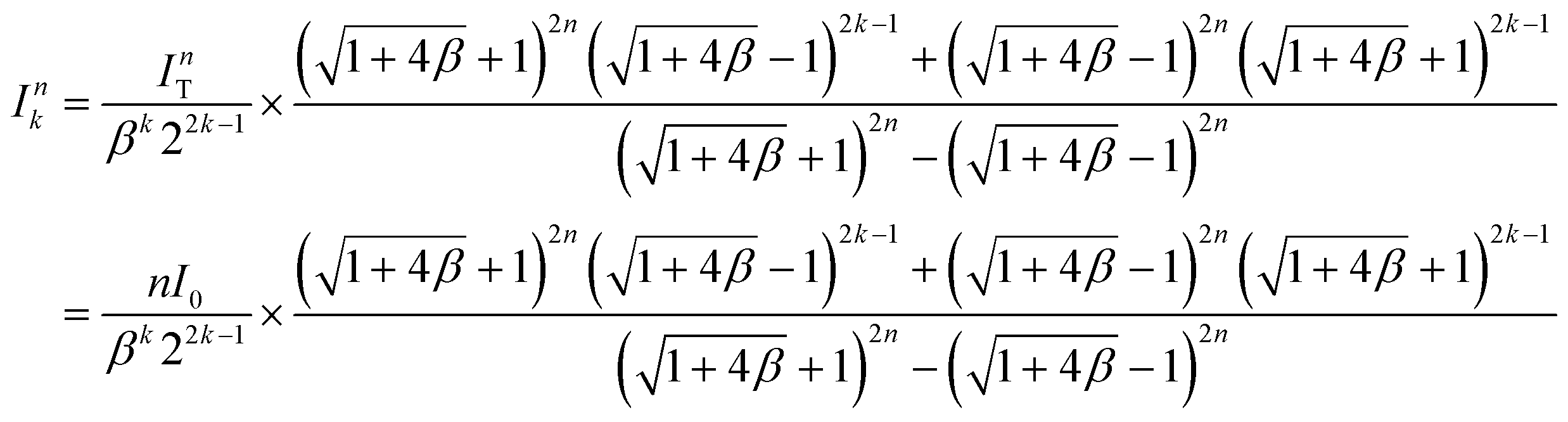 | (4) |
As shown in Fig. 4e, the first layer (k = 1) has the maximum variation in flow rate from the desired flow rate for a single device (I0). Based on the theoretical calculation of the flow rate in eqn (4), we derived a formula representing the maximum variation in flow rate as follows:
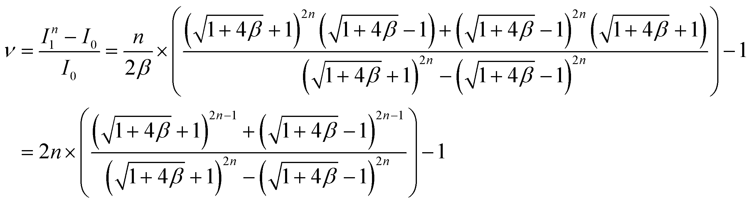 | (5) |
Fig. 4g shows the profile of the cell densities in the flask of the retained CHO cells (blue bar) and the cell-clarified output (green bar) and the cell-clarification efficiency (= cell-retention efficiency, red line). The initial CHO cell density was ∼2.14 × 10⁶ cells mL−1 in ∼1 L total volume, and input flow rate = 1 L min−1 at ∼4000 rpm for each pump, and flow rate split ratio = 15:1 (= the inner-outlet:the outer-outlet). The results clearly showed that the cell density in the flask was increased while harvesting nearly ∼80% of the cell-clarified supernatant from the original culture solution, over 12 min processing time. The cell-retention efficiency was maintained at ∼99% until the cell density in the flask became lower than 6 × 10⁶ cells mL−1 and slightly decreased to ∼95% as the cell density increased to near 10 × 106 cells mL−1. As shown in Fig. 4h, the cell viability in the flask was maintained as its initial value (∼90%), which means no significant cell damage during the operation as seen in the single plastic device test in Fig. 3i. The cell density in the flask was ∼4.37-fold increased from its initial density of ∼2.14 × 10⁶ cells mL−1 to the final density of ∼9.35 × 10⁶ cells mL−1 while the final cell density in the cell-clarified sample bottle was ∼0.105 × 10⁶ cells mL−1, which is only ∼4.90% of the initial input density (Fig. 4i). The results clearly showed that the developed multiplexed device can be used for cell retention and cell clarification at an ultra-high-throughput without cell damage (1 L min−1 per stacked unit, not limited and can be further increased by increasing the stacking number up to ∼100 layers per stacked unit), which could meet the throughput requirement in the biomanufacturing industry.
4. Discussion and conclusions
Although many theoretical analyses11,45–47 have previously been published to establish the relationship between channel dimensions and particle behavior in spiral inertial microfluidics, one still needs to rely on experimental trial-and-error testing to determine the optimal channel dimensions for a specific cell separation application. Benefitting from the advantages of the soft lithographic method in low-cost and rapid device prototyping, many inertial microfluidic devices have been successfully developed on a PDMS platform in the last decade. However, industrial deployment of inertial microfluidics on the PDMS platform is difficult due to channel deformation and other practical issues in terms of device manufacturing. While a hard plastic inertial microfluidic device would be a more reliable option for industrial applications,28 the high initial cost for fabrication (e.g., injection molding) is prohibitive in device engineering and optimization. We bridged this engineering gap by ‘translating’ previously developed PDMS inertial microfluidic devices to their deformation-free and mass-producible plastic equivalents. Based on the analysis of the channel deformation in the PDMS device, we can reliably determine the channel dimensions of the plastic device that would provide similar performance. Therefore, this work provides a systematic framework to transfer the accumulated library of inertial microfluidics design toward real-world industrial applications.Only a few papers analyzed the effects of material properties of the PDMS device on its performance.28,31,33,48 Deformation of the PDMS inertial device is coupled with the flow rate and pressure drop in a complicated manner, making it challenging to predict the device performance reliably. Nevertheless, a detailed device deformation analysis provides important information such as the average deformation ratio of the channel and the shape change of the channel cross-section to determine the channel dimensions of the plastic device more precisely. From the results, we found that the developed plastic devices showed comparable performance with their original PDMS devices. Therefore, this work could be an example to translate a proof-of-concept microfluidic device in the laboratory into a commercial and readily-deployable system in the real world, for bioanalytical, medical, and environmental applications.
Such translation would be a critical step to realize the vision of the high-throughput industrial application of inertial microfluidics,49 along with the massive parallelization of inertial devices demonstrated in this work. We identify and address the practical challenges arising from a ‘scale-out’ engineering of unit inertial microfluidic devices, to achieve macro-scale flow processing throughputs (∼a few L min−1). We presented a systematic analysis of the design of fluid interconnects in a massively-parallel microfluidic system, which is comparable to the challenges of interconnect design in microelectronics.
As a demonstrating example of industrial microfluidic implementation, we successfully demonstrated a rapid and clog-free CHO cell clarification process with a macroscopic volume processing rate (1 L min−1) and a high cell-clarification efficiency (∼99%, dependent on the CHO cell density). Not only is this a significant breakthrough in terms of high-throughput microfluidics, but the cell clarification demonstrated here is also superior to the conventional technologies demonstrated so far. Tangential flow filtration using hollow fiber membranes is commonly used for cell clarification in the industry.50 However, membrane fouling/clogging and low product recovery are major issues,51,52 hampering continuous and reliable cell clarification.
The results clearly show that the multiplexed plastic device can meet the required throughput in the biomanufacturing field and replace the conventional membrane-based filtration in the biomanufacturing industry by eliminating the need for membrane replacement and maintenance. Moreover, other advantages of inertial microfluidic filtration, such as high product recovery (>99%)40 and selective removal of cell types (e.g., nonviable cells),41 could further complement the conventional membrane-based filtration in a large-scale operation. In addition, with a clearly defined engineering methodology to increase the degree of multiplexing, there is virtually no limit in terms of the flow throughput and volume this technology can handle in the future, even up to the macroscopic volume scale (e.g., ∼1000 L bioreactor for production of biologics in the biopharmaceutical industry). We argue that this is the first demonstration of the industrial-scale application of inertial microfluidics, with many more potential applications to come in the future, such as high-throughput blood fractionation for blood transfusion, water purification (i.e., removal of microplastics and microalgae), and yeast filtration in the brewing process.
Author contributions
J. H. conceived and supervised the research. H. J. designed and carried out the experiments with the support of T. K. and J. Y. T. K. performed quantitative analysis on the CHO cell clarification. J. Y. and T. K. supported H. J. in developing the high-throughput cell-clarification platform. The manuscript was written by H. J., T. K., J. Y., and J. H.Conflicts of interest
There are no conflicts to declare.Acknowledgements
This work was performed under a Project Award Agreement from the National Institute for Innovation in Manufacturing Biopharmaceuticals (NIIMBL) and financial assistance award 70NANB17H002 from the U.S. Department of Commerce, National Institute of Standards and Technology. The authors thank Kyungyong Choi (MIT), Jack Huang (Merck), Douglas Rank (MilliporeSigma), David Pollard (Sartorius), Johannes Lemke (Sartorius), and Roger Rosche (WhirlCell) for their support and helpful comments.References
- J. Ministro, A. M. Manuel and J. Goncalves, in Advances in Biochemical Engineering/Biotechnology, ed. A. C. Silva, J. N. Moreira, J. M. S. Lobo and H. Almeida, Springer International Publishing, Cham, 2020, vol. 171, pp. 1–22 Search PubMed.
- S. S. Ozturk, Cell Cult. Eng., 2019, vol. i, pp. 347–364 Search PubMed.
- H. F. Liu, J. Ma, C. Winter and R. Bayer, mAbs, 2010, 2, 480–499 CrossRef PubMed.
- V. Chotteau, in Animal Cell Culture, ed. M. Al-Rubeai, Springer International Publishing, Cham, 2015, pp. 407–443 Search PubMed.
- H. Li and V. Chen, in Membrane Technology, Elsevier, 2010, pp. 213–254 Search PubMed.
- Y. Liao, A. Bokhary, E. Maleki and B. Liao, Bioresour. Technol., 2018, 264, 343–358 CrossRef CAS PubMed.
- W. Guo, H.-H. Ngo and J. Li, Bioresour. Technol., 2012, 122, 27–34 CrossRef CAS PubMed.
- D. Di Carlo, D. Irimia, R. G. Tompkins and M. Toner, Proc. Natl. Acad. Sci. U. S. A., 2007, 104, 18892–18897 CrossRef CAS PubMed.
- J. M. Martel and M. Toner, Annu. Rev. Biomed. Eng., 2014, 16, 371–396 CrossRef CAS PubMed.
- B. R. Mutlu, J. F. Edd and M. Toner, Proc. Natl. Acad. Sci. U. S. A., 2018, 115, 7682–7687 CrossRef CAS PubMed.
- D. Di Carlo, Lab Chip, 2009, 9, 3038 RSC.
- E. Lin, L. Rivera-Báez, S. Fouladdel, H. J. Yoon, S. Guthrie, J. Wieger, Y. Deol, E. Keller, V. Sahai, D. M. Simeone, M. L. Burness, E. Azizi, M. S. Wicha and S. Nagrath, Cell Syst., 2017, 5, 295–304.e4 CrossRef CAS PubMed.
- S. Wan, T. H. Kim, K. J. Smith, R. Delaney, G. S. Park, H. Guo, E. Lin, T. Plegue, N. Kuo, J. Steffes, C. Leu, D. M. Simeone, N. Razimulava, N. D. Parikh, S. Nagrath and T. H. Welling, Sci. Rep., 2019, 9, 1–11 Search PubMed.
- B. Jundi, H. Ryu, D.-H. Lee, R.-E. E. Abdulnour, B. D. Engstrom, M. G. Duvall, A. Higuera, M. Pinilla-Vera, M. E. Benson, J. Lee, N. Krishnamoorthy, R. M. Baron, J. Han, J. Voldman and B. D. Levy, Nat. Biomed. Eng., 2019, 3, 961–973 CrossRef CAS PubMed.
- L. Wu, G. Guan, H. W. Hou, A. A. S. Bhagat and J. Han, Anal. Chem., 2012, 84, 9324–9331 CrossRef CAS PubMed.
- H. Ryu, K. Choi, Y. Qu, T. Kwon, J. S. Lee and J. Han, Anal. Chem., 2017, 89, 5549–5556 CrossRef CAS PubMed.
- B. R. Mutlu, K. C. Smith, J. F. Edd, P. Nadar, M. Dlamini, R. Kapur and M. Toner, Sci. Rep., 2017, 7, 1–9 CrossRef CAS PubMed.
- H. W. Hou, M. E. Warkiani, B. L. Khoo, Z. R. Li, R. A. Soo, D. S. W. Tan, W. T. Lim, J. Han, A. A. S. Bhagat and C. T. Lim, Sci. Rep., 2013, 3, 1–8 Search PubMed.
- J. Wang, W. Lu, C. Tang, Y. Liu, J. Sun, X. Mu, L. Zhang, B. Dai, X. Li, H. Zhuo and X. Jiang, Anal. Chem., 2015, 87, 11893–11900 CrossRef CAS PubMed.
- M. E. Warkiani, B. L. Khoo, L. Wu, A. K. P. Tay, A. A. S. Bhagat, J. Han and C. T. Lim, Nat. Protoc., 2016, 11, 134–148 CrossRef CAS PubMed.
- M. E. Warkiani, B. L. Khoo, D. S.-W. Tan, A. A. S. Bhagat, W.-T. Lim, Y. S. Yap, S. C. Lee, R. A. Soo, J. Han and C. T. Lim, Analyst, 2014, 139, 3245–3255 RSC.
- E. Ozkumur, A. M. Shah, J. C. Ciciliano, B. L. Emmink, D. T. Miyamoto, E. Brachtel, M. Yu, P. Chen, B. Morgan, J. Trautwein, A. Kimura, S. Sengupta, S. L. Stott, N. M. Karabacak, T. A. Barber, J. R. Walsh, K. Smith, P. S. Spuhler, J. P. Sullivan, R. J. Lee, D. T. Ting, X. Luo, A. T. Shaw, A. Bardia, L. V. Sequist, D. N. Louis, S. Maheswaran, R. Kapur, D. A. Haber and M. Toner, Sci. Transl. Med., 2013, 5, 179ra47 Search PubMed.
- L. Yin, Y. Wu, Z. Yang, C. A. Tee, V. Denslin, Z. Lai, C. T. Lim, E. H. Lee and J. Han, Lab Chip, 2018, 18, 878–889 RSC.
- H. W. Hou, R. P. Bhattacharyya, D. T. Hung and J. Han, Lab Chip, 2015, 15, 2297–2307 RSC.
- K. Choi, H. Ryu, K. J. Siddle, A. Piantadosi, L. Freimark, D. J. Park, P. Sabeti and J. Han, Anal. Chem., 2018, 90, 4657–4662 CrossRef CAS PubMed.
- M. E. Warkiani, A. K. P. Tay, G. Guan and J. Han, Sci. Rep., 2015, 5, 11018 CrossRef PubMed.
- D. Riedel and B. Mizaikoff, Surface Imprinted Micro- and Nanoparticles, Elsevier B.V., 1st edn, 2019, vol. 86 Search PubMed.
- E. Sollier, C. Murray, P. Maoddi and D. Di Carlo, Lab Chip, 2011, 11, 3752 RSC.
- Z. Wang, A. A. Volinsky and N. D. Gallant, J. Appl. Polym. Sci., 2014, 131, 1–4 CrossRef.
- I. D. Johnston, D. K. McCluskey, C. K. L. Tan and M. C. Tracey, J. Micromech. Microeng., 2014, 24, 035017 CrossRef CAS.
- B. S. Hardy, K. Uechi, J. Zhen and H. Pirouz Kavehpour, Lab Chip, 2009, 9, 935–938 RSC.
- C. Kang, C. Roh and R. A. Overfelt, RSC Adv., 2014, 4, 3102–3112 RSC.
- T. Gervais, J. El-Ali, A. Günther and K. F. Jensen, Lab Chip, 2006, 6, 500–507 RSC.
- S. Razavi Bazaz, O. Rouhi, M. A. Raoufi, F. Ejeian, M. Asadnia, D. Jin and M. Ebrahimi Warkiani, Sci. Rep., 2020, 10, 1–14 CrossRef PubMed.
- L. R. Volpatti and A. K. Yetisen, Trends Biotechnol., 2014, 32, 347–350 CrossRef CAS PubMed.
- C. D. Chin, V. Linder and S. K. Sia, Lab Chip, 2012, 12, 2118–2134 RSC.
- H. Jeon, H. Lee, K. H. Kang and G. Lim, Sci. Rep., 2013, 3, 03483 CrossRef PubMed.
- H. Jeon, Y. Kim and G. Lim, Sci. Rep., 2016, 6, 19911 CrossRef CAS PubMed.
- H. Jeon, B. Jundi, K. Choi, H. Ryu, B. D. Levy, G. Lim and J. Han, Lab Chip, 2020, 20, 3612–3624 RSC.
- T. Kwon, H. Prentice, J. De Oliveira, N. Madziva, M. E. Warkiani, J.-F. F. P. Hamel and J. Han, Sci. Rep., 2017, 7, 6703 CrossRef PubMed.
- T. Kwon, R. Yao, J. F. P. Hamel and J. Han, Lab Chip, 2018, 18, 2826–2837 RSC.
- T. Kwon, S. H. Ko, J. F. P. Hamel and J. Han, Anal. Chem., 2020, 92, 5267–5275 CrossRef CAS PubMed.
- T. Laurell, F. Petersson and A. Nilsson, Chem. Soc. Rev., 2007, 36, 492–506 RSC.
- K. W. Oh, K. Lee, B. Ahn and E. P. Furlani, Lab Chip, 2012, 12, 515–545 RSC.
- J. Zhang, S. Yan, D. Yuan, G. Alici, N. T. Nguyen, M. Ebrahimi Warkiani and W. Li, Lab Chip, 2016, 16, 10–34 RSC.
- N. Liu, C. Petchakup, H. M. Tay, K. H. H. Li and H. W. Hou, Spiral Inertial Microfluidics for Cell Separation and Biomedical Applications, in Applications of Microfluidic Systems in Biology and Medicine, ed. M. Tokeshi, Bioanalysis (Advanced Materials, Methods, and Devices), Springer, Singapore, 2019, vol. 7, DOI:10.1007/978-981-13-6229-3_5.
- N. Herrmann, P. Neubauer and M. Birkholz, Biomicrofluidics, 2019, 13, 061501 CrossRef CAS PubMed.
- H. Sun, C. W. Chan, Y. Wang, X. Yao, X. Mu, X. Lu, J. Zhou, Z. Cai and K. Ren, Lab Chip, 2019, 19, 2915–2924 RSC.
- M. E. Warkiani, L. Wu, A. K. P. Tay and J. Han, Annu. Rev. Biomed. Eng., 2015, 17, 1–34 CrossRef CAS PubMed.
- A. L. Zydney, Biotechnol. Bioeng., 2016, 113, 465–475 CrossRef CAS PubMed.
- M. Stressmann and C. Moresoli, Biotechnol. Prog., 2008, 24, 890–897 CrossRef CAS PubMed.
- G. R. Bolton and A. J. Apostolidis, Biotechnol. Prog., 2017, 33, 1323–1333 CrossRef CAS PubMed.
Footnote |
| † Electronic supplementary information (ESI) available. See DOI: 10.1039/d1lc00995h |
| This journal is © The Royal Society of Chemistry 2022 |