
 Open Access Article
 This Open Access Article is licensed under a Creative Commons Attribution-Non Commercial 3.0 Unported Licence
Separation and isotope ratio measurements of actinides and lanthanides in spent nuclear fuel samples by CE-MC-ICP-MS†
Erwan
Dupuis
 *a,
Hélène
Isnard
a and
Frédéric
Chartier
b
*a,
Hélène
Isnard
a and
Frédéric
Chartier
b
aUniversité Paris-Saclay, CEA, Service d'Études Analytiques et de Réactivité des Surfaces, 91191, Gif-sur-Yvette, France. E-mail: erwan.dupuis@cea.fr
bUniversité Paris-Saclay, CEA, Département de Physico-Chimie, 91191, Gif-sur-Yvette, France. E-mail: erwan.dupuis@cea.fr
First published on 4th October 2022
Abstract
Capillary electrophoresis (CE) was hyphenated to Multi-Collector Inductively Coupled Plasma Mass Spectrometry (MC-ICP-MS) to perform isotope ratio measurements for actinides (U, Pu, Am, and Cm) and lanthanide fission products (Nd, Sm, Eu, and Gd) in a spent nuclear fuel sample. A capillary electrophoresis-inductively coupled plasma mass spectrometry (CE-ICP-MS) method was developed using either α-HMBA or α-HIBA as electrolytes, demonstrating the ability of alpha-hydroxycarboxylic acids to perform the concurrent separation of actinides and lanthanides in a simulated sample and a spent Mixed Oxide (MOX) fuel sample. Isotope ratios for U, Pu, Am, and Cm as well as Nd, Sm, Eu, and Gd were then determined by CE-MC-ICP-MS in two injections of approximately 30 nL of the spent MOX fuel sample. The relative standard deviations were in the per-mil range, similar to the ones obtained by two-step offline chromatography followed by Thermal Ionisation Mass Spectrometry (TIMS). The use of CE as the separation method lowered the sample quantity (in the pg range for Pu, Am, Cm and lanthanides, in the ng range for U) and waste volume production (a few hundred μL) as compared to commonly used chromatography methods. CE-MC-ICP-MS therefore makes it possible to measure multiple isotope ratios at a per-mil level of uncertainty without the need for prior offline chemical separation.
Introduction
Knowing the isotopic and elemental composition of spent nuclear fuel samples is crucial for the reprocessing of spent fuel as well as for waste storage. Numerical calculation methods such as neutronics computer codes render it possible to estimate the isotopic and elemental composition of spent nuclear fuel but they need to be experimentally validated.1–3The validation of neutronics computer codes requires experimental measurements of the isotopic and elemental composition of spent nuclear fuel samples with a per-mil level of uncertainty. The elements of interest in this study were the actinides (An, e.g. U, Np, Pu, Am, and Cm) and lanthanide fission products (Ln, e.g. Nd, Sm, Eu, and Gd) contained in a spent Mixed OXide (MOX) fuel sample.
Thermal ionisation mass spectrometry (TIMS) and multicollector inductively coupled plasma mass spectrometry (MC-ICP-MS) are commonly used for isotope ratio measurements at a per-mil level of uncertainty.4,5 It is also possible to determine elemental concentrations with a per-mil level of uncertainty using the isotope dilution method in conjunction with TIMS or MC-ICP-MS.6 However, due to the presence of interferences or matrix effects, one or several chemical separation steps need to be performed prior to analysis. Another way of overcoming these issues is to use collision–reaction cells,7–9 but this will not be discussed in detail here.
To chemically separate elements in nuclear samples, chromatographic methods are commonly used. In our laboratory, the chemical separation of actinides and lanthanide fission products in spent nuclear fuel samples is performed in two steps. The first one is anion-exchange or extraction chromatography (AG-1 or TEVA resin)10,11 resulting in pure U and Pu fractions and in a mixed fraction containing Am, Cm as well as the lanthanide fission products. The U and Pu fractions are directly recovered for mass spectrometric measurements.
The second step consists in separating Am, Cm, and lanthanide fission products in the mixed fraction by high-performance liquid chromatography (HPLC) using a strong cation exchange column with a mobile phase composed of alpha-hydroxymethylbutyric acid (α-HMBA).10–13 Alpha-hydroxycarboxylic acids (α-HCA) such as α-HMBA or alpha-hydroxyisobutyric acid (α-HIBA) have been used to perform the cation exchange separation of Ln(III) and An(III) since 1964 and 1956, respectively.10,13–15 In this case, the separation of Ln(III) and An(III) is caused by the difference in complexation between these elements and α-HIBA or α-HMBA.16
The uncertainty of isotope ratios after this two-step chromatographic separation of elements and offline TIMS or MC-ICP-MS measurements is in the per-mil range or better. However, these methods are associated with sample volumes of several hundreds of μL and the production of effluents in the range of tens or hundreds of mL. In the case of spent nuclear fuel, the sample is radioactive and the effluents are radioactive waste. It is therefore necessary to develop analytical methods requiring less sample volume, producing less waste while additionally minimizing operator manipulations.
Liquid chromatography techniques can be hyphenated to MC-ICP-MS for isotope ratio measurements. Isotope ratios for uranium, plutonium and fission products were determined in spent nuclear fuel samples by HPLC-ICP-MS.17–20 HPLC-MC-ICP-MS yields uncertainties in the per-mil range while minimizing manipulations in the glove box. HPLC-MC-ICP-MS is therefore one of the solutions available for reducing waste volumes.
In order to downscale sample quantities and waste volumes while maintaining the measurement uncertainty in the per-mil range, another option is to employ alternative separation techniques. Among these techniques, capillary electrokinetic techniques such as capillary electrophoresis (CE) or capillary isotachophoresis (ITP) allow immediate downscaling with common capillary volumes lying in the μL range and injected sample quantities in the nL range (or lower).21 Furthermore, CE or ITP can be hyphenated with ICP-MS in CE-ICP-MS or ITP-ICP-MS experiments.22–24
Electrokinetic methods have already been employed for lanthanide separations. As early as 1965, α-HIBA was used for the separation of Ln(III) in a paper electrophoresis experiment, in the presence of unseparated Am(III) and Cm(III).25 α-HIBA containing electrolytes were later used for CE-ICP-MS separations of Ln(III) in classical and nuclear samples.26–28 Isotope ratios of natural lanthanides were also determined by capillary ITP coupled to MC-ICP-MS using α-HMBA as the separation electrolyte.22
Moreover, actinide separations employing electrokinetic methods have been described previously. α-Alanin was used as electrolyte for the CE-ICP-MS separation of Am(III), U(VI), Np(V), and Pu under various oxidation states.28 Acetic acid containing electrolytes were utilized for CE-ICP-MS separation of actinides in samples containing U, Np, Pu, and Am.29–31 Isotope ratios of U and Pu in a spent MOX fuel sample were also measured by CE hyphenated to MC-ICP-MS (CE-MC-ICP-MS) while lanthanides, americium and curium remained unseparated using an acetic acid electrolyte.32 Furthermore, a previous study has demonstrated the feasibility of separating U(VI) and Th(IV) with CE-ICP-MS using α-HMBA as the separation electrolyte.33 For the CE-ICP-MS separations involving Pu, several Pu peaks were often obtained corresponding to the different Pu oxidation states.28–32 The stabilization of Pu to one of these oxidation states is therefore required to obtain a single Pu peak.
Even though α-HMBA has been utilized in order to carry out separate CE-ICP-MS analyses of Ln(III) as well as of U(VI) and Th(IV),22,26–28,33 to our knowledge it has never been employed to perform the concurrent CE-ICP-MS separation of Ln(III) and actinides. The first objective of this work was therefore to study the separation of both actinides and lanthanide fission products contained in a spent MOX fuel sample in a single CE-ICP-MS experiment using α-HMBA or α-HIBA as the electrolyte. The second objective was to apply the developed separation to the measurement of isotope ratios in the spent MOX fuel sample, with an uncertainty level in the per-mil range, using CE-MC-ICP-MS.
This investigation was performed in three parts, where the first part was focused on the development of separation conditions with a simulated sample containing natural lanthanides, uranium and thorium in a conventional laboratory. The second part was aimed at validating the CE separation method of lanthanides and actinides with a spent MOX fuel sample in a glove box permitting safe handling of nuclear samples. The final part of the study was devoted to the measurement of actinides and fission products isotope ratios in the spent MOX fuel sample using CE-MC-ICP-MS, in order to verify our approach. The results are discussed and compared with the ones obtained with the conventional liquid chromatography approach.
Material and methods
Capillary electrophoresis
The first step was to conduct an optimization of the CE separation, and this was done with samples containing elements that can be handled outside glove boxes. In this case, samples were prepared from a mixture of the 14 naturally occurring lanthanides (La, Ce, Pr, Nd, Sm, Eu, Gd, Tb, Dy, Ho, Er, Tm, Yb, Lu), uranium and thorium, all obtained from stock solutions (Spex Certiprep, approximately 995 μg g−1). The mixture was diluted with the electrolyte to reach a concentration of approximately 1 μg g−1 for each element.
For the rest of the study, a spent MOX fuel sample was employed. A few grams of solid spent MOX fuel were dissolved in boiling nitric acid in a hot cell of the ATALANTE facility at CEA Marcoule.34 The MOX fuel solution was then diluted with concentrated nitric acid (8 mol L−1) and sent to CEA Saclay where the spent MOX fuel sample was handled in glove boxes.
The spent MOX fuel sample contained actinides (U, Np, Pu, Am, and Cm), lanthanide fission products (including Nd, Sm, Eu, Gd) and other fission products not measured in this work (mainly Cs, Ba and platinoids) in a 8 mol L−1 nitric acid matrix. The relative abundance of these elements in the spent MOX fuel sample used in this study, as calculated by neutronics computer codes, is presented in Fig. 1.
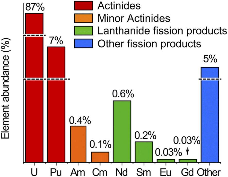 | ||
| Fig. 1 Relative abundance of the actinides and lanthanide fission products in the spent MOX fuel sample used in this study, as calculated by neutronics computer codes. Line breaks are present for the highly abundant U and Pu and for the group of other fission products. | ||
It was shown in previous studies that Pu(VI) was a suitable oxidation state for CE separation of Pu from U(VI).29,32 Aliquots of the spent MOX fuel sample were therefore oxidized with concentrated perchloric acid on a hot plate similarly to a protocol described elsewhere.32 At the end of the oxidation procedure, the dry residue obtained was dissolved in the separation electrolyte before separation by CE.
For the second part of the study (validation of CE separation conditions), the uranium concentration was approximately 500 μg g−1 and for the final part of the study (isotope ratio measurements by CE-MC-ICP-MS), two samples were prepared: one for actinides (U, Pu, Am, and Cm) and another, more concentrated aliquot, for lanthanide fission products (Nd, Sm, Eu, and Gd). The uranium concentrations for these two samples were approximately 500 and 1500 μg g−1.
For the validation of CE separation conditions and for isotope ratio measurements, a custom CE system was used, as described elsewhere.32,33 A Fluigent Maesflow controller was used to perform hydrodynamic injections of the sample corresponding to 1% of the capillary volume. The voltage was applied using a separate high-voltage supply (Spellman) and a gold electrode. Pressure was applied to the inlet vial using the Fluigent Maesflow controller.
 | (1) |
The electroosmotic mobility was calculated using eqn (2) from the length of the capillary L, the applied voltage U, and the migration time of neutral species tn, measured by Q-ICP-MS at m/z = 69 with the Ga–NOTA complex.21
 | (2) |
In order to optimize the α-HCA concentration for the separation, the resolution between Nd and Sm was calculated from the migration times tm1, tm2 and the widths of the peaks (at 4σ) w1, w2 using eqn (3).35
 | (3) |
Inductively coupled plasma mass spectrometry
Optimization of the CE separation was performed using an Agilent 7700 Series Q-ICP-MS located in a conventional laboratory. Validation of CE separation conditions with the spent MOX fuel sample was done using a Thermo XSeries II Q-ICP-MS. Finally, a Thermo Neptune MC-ICP-MS was employed for isotope ratio measurements. The XSeries II and Neptune ion sources and introduction systems are located in a glove box as these instruments are dedicated to the analysis of nuclear samples.7,19To carry out the isotope ratio measurements of all actinides and lanthanides with MC-ICP-MS, two separate CE injections were necessary, using two different Faraday cup configurations. A first cup configuration was designed for measuring the lanthanides and a second one for the actinides. These configurations were chosen to measure isotopes between 140Ce and 160Gd (for the lanthanides) and between 234U and 247Cm (for the actinides). Subconfigurations were designed to cover the whole mass range without moving the Faraday cups. To switch from one subconfiguration to another, the magnetic field strength was varied and the zoom optics voltages were also changed to realign the ion signals on the Faraday cups. This process was faster as compared to a full cup configuration change. The different cup configurations and subconfigurations are presented in Tables S1 and S2 of the ESI.† Current amplifiers with 1011 and 1012 Ω resistors were used.
For optimization and validation of CE separation conditions, a single-inlet, 45 mL cyclonic spray chamber was used. For isotope ratio measurements with MC-ICP-MS, a dual inlet spray chamber was employed.32 The first inlet was dedicated to the CE nebulizer while the second was allocated to standard injection for mass bias correction. A valve system was used to switch between 2% nitric acid which was sprayed continuously and the mass-bias standard which was sprayed only during standard injection.
Raw isotope ratios were determined from the ICP-MS signals using the Linear Regression Slope (LRS) method as described in previous studies.13,32,37 The Tau correction included in the NeptunePlus software was applied.38
Precision was evaluated by performing CE-MC-ICP-MS injections of the MOX fuel sample (five injections for the actinides, six injections for the lanthanides) and calculating the relative standard deviation of the isotope ratios on these determinations. The relative difference between the results obtained with the CE-MC-ICP-MS method and reference values obtained by two-step chromatography and offline measurement by TIMS or MC-ICP-MS was calculated.10,39 The reference values were corrected for radioactive decay to the date of the CE-MC-ICP-MS measurements, using decay constants from the Decay Data Evaluation Project (DDEP).40
In order to validate the lanthanide mass bias correction, neodymium, samarium, europium, and gadolinium from stock solutions (SPEX Certiprep, 995 μg g−1) were used. These solutions were qualified by TIMS using the total evaporation method. For uranium, a certified isotopic reference material, IRMM-186, was used. In-house plutonium, americium, and curium solutions, characterized by TIMS using the total evaporation method, were taken for the validation of the actinide mass bias correction.
For each of these standards, isotope ratios were measured by MC-ICP-MS in the continuous mode. Raw isotope ratios obtained for each element were then corrected using inter-element correction (using the Nd standard and the in-house Pu standard for lanthanides and actinides, respectively). The relative difference between the obtained isotope ratios and the reference value (certified or measured by TIMS in our laboratory) was calculated to be inferior to 0.2% in all cases, which validated the inter-element mass bias correction.
Neodymium of natural isotopic composition was therefore selected for the mass bias correction of Nd, Sm, Eu, and Gd isotope ratios. All lanthanide isotope ratios were corrected with the 146Nd/144Nd ratio with a reference value of 0.72333 ± 0.00008, determined by TIMS with a total evaporation (TE) method.43
Similarly, the in-house plutonium standard was selected for the mass-bias correction of U, Pu, Am and Cm isotope ratios. The 240Pu/239Pu ratio of this standard was previously determined by TIMS with a sequential method and had a value of 0.06267 ± 0.00008. This standard is used as a quality control sample in our laboratory and is therefore well characterized.
Results and discussion
Optimization of CE separation conditions with a synthetic sample
The first part of this study aims at selecting an appropriate electrolyte to carry out the concurrent CE separation of lanthanides and actinides, with the synthetic sample containing the 14 natural lanthanides, uranium, and thorium. Two complexing agents, α-HIBA and α-HMBA, with seven concentrations ranging from 5 to 500 mmol L−1 and at a pH of 3, were studied. The two criteria for electrolyte selection were the Nd/Sm resolution and the electrophoretic mobility of uranium. The Nd/Sm resolution was selected as a criterion as it was expected that Am and Cm would migrate between these elements, as observed in HPLC with α-HMBA in the mobile phase.12 For each α-HCA concentration, the resolution between Nd and Sm as well as the electrophoretic mobility of the 14 lanthanides, uranium and thorium was calculated. The electrophoretic mobility of uranium had to be positive in order for uranium to migrate towards the ICP-MS without applying pressure to the inlet vial. The results obtained with α-HMBA are presented first followed by the results obtained with α-HIBA. The complexing agent used in the rest of the study was then pre-selected according to these two criteria.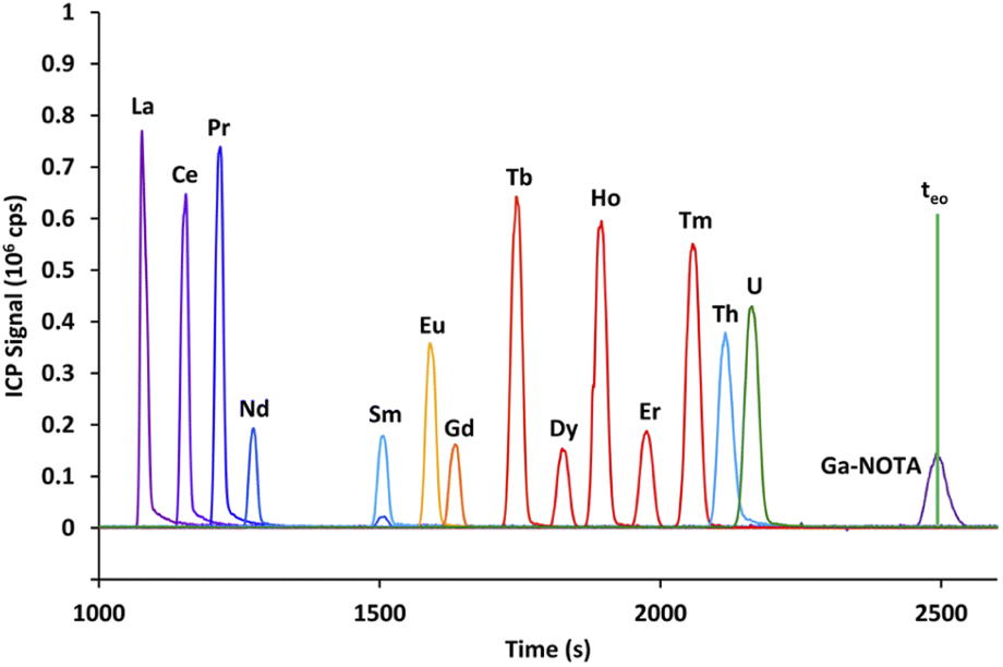 | ||
| Fig. 2 Electropherogram obtained by CE-Q-ICP-MS for the mixture containing 14 lanthanides, uranium and thorium with a 100 mmol L−1 α-HMBA electrolyte. Here, teo is the time where neutrals migrate, as calculated at the apex of the Ga–NOTA peak. Yb and Lu were omitted from the figure for visibility reasons. | ||
It is clear from Fig. 2 that using α-HMBA as the complexing agent led to the lanthanides migrating in increasing order of atomic number (from La to Lu). This behavior was true for all α-HMBA concentrations and was a result of higher complexation of α-HMBA with heavier lanthanides, caused by the lanthanide contraction.16 Nd and Sm were easily separated (Rs = 7.8) while Eu and Gd was the most difficult pair to resolve (Rs = 1.25).
Uranium and thorium co-migrated with heavier lanthanides, but this was not problematic as heavier lanthanides (starting from Dy) are not present in quantifiable amounts in spent MOX fuel samples (as calculated by neutronics computer codes and verified by Q-ICP-MS), and are separated from the actinides by the mass spectrometer.
In order to study the effect of the α-HMBA concentration on the electrophoretic migration of lanthanides and actinides, analyte electrophoretic mobilities were calculated for each α-HMBA concentration. A plot of the electrophoretic mobilities of Nd, Sm, Eu, Gd, Th, and U as a function of the α-HMBA concentration is presented in Fig. 3.
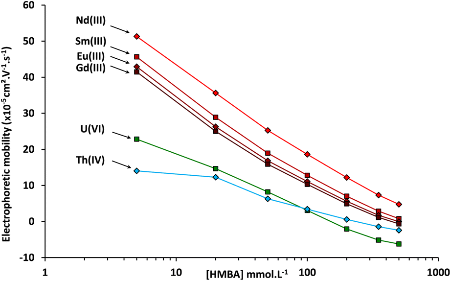 | ||
| Fig. 3 Electrophoretic mobilities measured by CE-Q-ICP-MS of Nd, Sm, Eu, Gd, Th, and U as a function of the α-HMBA concentration at a pH of 3. | ||
It can be seen in Fig. 3 that the electrophoretic mobilities of the lanthanides and actinides decreased as the α-HMBA concentration was raised as a result of increased complexation. The criterion of positive electrophoretic mobility for uranium was not met over an α-HMBA concentration of 150 mmol L−1, as presented in Fig. 3. In any case, it was proven that the CE separation of the 14 lanthanides, uranium, and thorium was achieved using α-HMBA as the electrolyte.
The general trends obtained with α-HMBA and α-HIBA were similar. This can be explained by the fact that α-HMBA and α-HIBA have comparable chemical structures and chemical properties.44 Nevertheless, slight differences were observed. There was less overlap between the Eu and Gd peaks using α-HIBA, while the difference in migration times between Nd and Sm was higher using α-HMBA.
The resolution between Nd and Sm increased when the α-HCA concentration was higher. The Nd/Sm resolution obtained with α-HIBA was lower than the one obtained for α-HMBA for each of the concentrations studied. α-HMBA was therefore selected to perform the CE separation of actinides and lanthanide fission products in the spent MOX fuel sample. It is important to note that if the priority is Eu/Gd separation, α-HIBA should be selected. This demonstrates the versatility of the use of α-HCA for CE separations of actinides and lanthanide fission products.
After choosing α-HMBA as the electrolyte, it was still necessary to select the optimal α-HMBA concentration. As the Nd/Sm resolution increased with the α-HMBA concentration, the chosen α-HMBA concentration should be the highest for which the electrophoretic mobility of uranium was still positive. According to Fig. 3, the electrophoretic mobility of uranium was zero for an α-HMBA concentration of approximately 150 mmol L−1. In order for the electrophoretic mobility of uranium to be slightly positive, an α-HMBA concentration of 120 mmol L−1 was preselected for isotope ratio measurements of actinides and lanthanide fission products in the spent MOX fuel sample. However, the ability of α-HMBA to separate Pu, Am, and Cm first had to be validated. The next part of the study deals with this validation by means of CE-Q-ICP-MS separations of elements in a spent MOX fuel sample.
Validation of CE separation conditions by CE-Q-ICP-MS with a spent MOX fuel sample
The second part is devoted to the validation of these conditions for Pu, Am, and Cm, as well as for the lanthanides in a spent MOX fuel sample by CE-Q-ICP-MS. Prior to the CE separation, the spent MOX fuel sample was oxidized using hot concentrated perchloric acid in order to oxidize plutonium in its +VI state.32,45 From preliminary results not presented here, it was found that plutonium was present not only as Pu(VI) and that the amount of the different redox species evolved as a function of time. To study this evolution, two electropherograms were acquired; the first one the day after the end of the oxidation step, and the second seven days later. These electropherograms, acquired with an α-HMBA concentration of 120 mmol L−1, are presented in Fig. 4.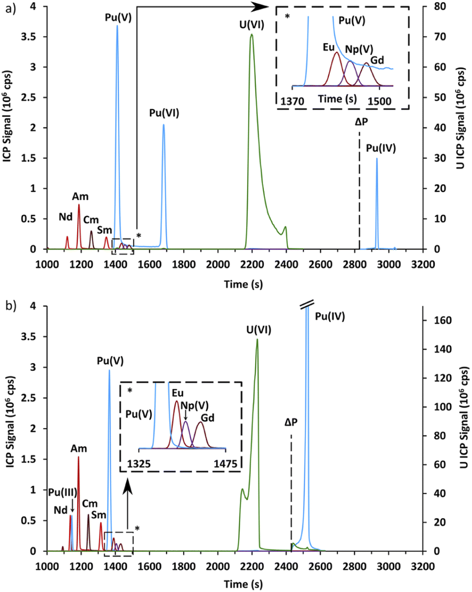 | ||
| Fig. 4 (a) Electropherogram obtained by CE-Q-ICP-MS for a spent MOX fuel sample with a 120 mmol L−1 α-HMBA electrolyte one day after the end of the oxidation step. (b) Electropherogram obtained by CE-Q-ICP-MS for a spent MOX fuel sample with a 120 mmol L−1 α-HMBA electrolyte seven days after the end of the oxidation step. For both electropherograms, it was necessary to apply 1 bar of pressure in order for Pu(IV) to migrate. The time at which the pressure (ΔP) was applied is symbolized as a dashed line. | ||
The electropherograms presented in Fig. 4 show that Am(III) and Cm(III) were separated and migrated between Nd(III) and Sm(III), as expected. Np(V) migrated between Eu(III) and Gd(III).
Four different peaks were observed for plutonium, with only three peaks present in each electropherogram. These peaks were attributed using chemical analogy. The first peak which migrated at 1127 s in Fig. 4b migrated just before Am(III) and Cm(III). It was therefore attributed to Pu(III). The second peak which migrated just before Np(V) in Fig. 4a and b was attributed to Pu(V). The attribution of the third Pu peak is discussed in the following paragraph. The last peak in Fig. 4a and b migrated only when pressure was applied. This peak was attributed to Pu(IV) which is known to be unstable above pH 0 due to the formation of polynuclear species and colloids.45
Finally, the Pu peak which was present only in Fig. 4a and migrated at approximately 1680 s was attributed to Pu(VI) by elimination and for two other reasons. First, this peak disappeared in Fig. 4b while Pu(III) appeared, which would indicate an overall reduction of plutonium. Secondly, the signal did not return to the baseline in Fig. 4a between this peak and the Pu(V) peak, with a constant signal of about 50![[thin space (1/6-em)]](https://www.rsc.org/images/entities/char_2009.gif) 000 cps. This could be interpreted as redox reactions occurring during the CE separation, namely the reduction of Pu(VI) or the oxidation of Pu(V), according to the following reaction:
000 cps. This could be interpreted as redox reactions occurring during the CE separation, namely the reduction of Pu(VI) or the oxidation of Pu(V), according to the following reaction:
| PuO22+ + e− = PuO2+ | (4) |
This equilibrium, involving only an electron exchange, was described as fast in the literature46 and was believed to take place as the Pu species are separated by CE.
In order to verify the attribution of the plutonium peaks and to gain further information about the separation of actinides by CE with α-HCA as the electrolyte, the systematic approach used with the simulated sample was repeated with the spent MOX fuel sample. The CE-Q-ICP-MS separation and analysis for the spent MOX fuel sample was therefore realized with α-HMBA concentrations of 5, 20, 50, 100, 200, 350 and 500 mmol L−1. With the use of Ga(NOTA) as the electroosmotic mobility marker, it was possible to determine the electrophoretic mobilities of analytes using the CE setup in the glove box for each of these concentrations. The plot of electrophoretic mobilities for Nd, Sm, Am, Cm, Np, U, and Pu is presented in Fig. 5.
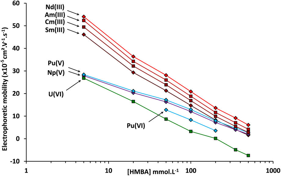 | ||
| Fig. 5 Electrophoretic mobilities measured by CE-Q-ICP-MS of Nd, Sm, U, Pu, Np, Am, and Cm as a function of the α-HMBA concentration at a pH of 3. | ||
The general trend for Nd, Sm, Am, Cm, Np, U and Pu is a decrease in electrophoretic mobility as the α-HMBA concentration increased, due to greater complexation. Americium and curium follow a comparable trend over the whole concentration range. This reflects the fact that these elements are in the same oxidation state (+III) and have similar ionic radiuses.47 Np(V) and the peak attributed to Pu(V) also had the same tendency over the whole concentration range which could also be caused by a similarity in oxidation state, strengthening the attribution of this Pu peak to Pu(V). Finally, the peak attributed to Pu(VI), present only for some of the concentrations studied, was closer to U(VI) in terms of electrophoretic mobility, again strengthening the attribution of this Pu peak to Pu(VI).
To conclude, it was proven that lanthanide fission products as well as U, Am, Cm, and Pu in four oxidation states were separated by CE using α-HMBA at a concentration of 120 mmol L−1 as the electrolyte. The developed CE separation was robust against the presence of several Pu oxidation states, as the separation was possible whether Pu was in its +VI, +V or +III state. However, Pu(III) is not recommended to perform the separation because of an interference with 241Am(III) if the 241Pu(III) amount is too high.
Measurement of actinides and fission products isotope ratios in a spent MOX fuel sample using CE-MC-ICP-MS
The third part deals with isotope ratio measurements by CE-MC-ICP-MS of Nd, Sm, Eu, Gd, U, Pu, Am, and Cm contained in the spent MOX fuel sample. The repeatability and trueness obtained by CE-MC-ICP-MS were then compared to the ones found with the reference method, i.e., two-step chromatography followed by offline measurement by TIMS or MC-ICP-MS.10,12For isotope ratio measurements, as the multicollector array has a limited number of detectors (9 in the case of the NeptunePlus), it was only possible to simultaneously measure up to 9 different isotopes. Furthermore, with the use of α-HMBA as the complexing agent, some lanthanides and actinides (such as plutonium and europium) migrate a few seconds from one another while the required time to switch from a lanthanide to an actinide cup configuration is in the order of minutes using the NeptunePlus MC-ICP-MS.
Therefore, two separate CE injections were needed. One was performed for the measurement of actinide (U, Pu, Am, and Cm) isotope ratios while another CE injection was carried out to determine the isotope ratios of the fission products (Nd, Sm, Eu, and Gd). A more concentrated sample was chosen for the isotope ratio measurements of lanthanide fission products in order to obtain more signal on the MC-ICP-MS for minor isotopes.
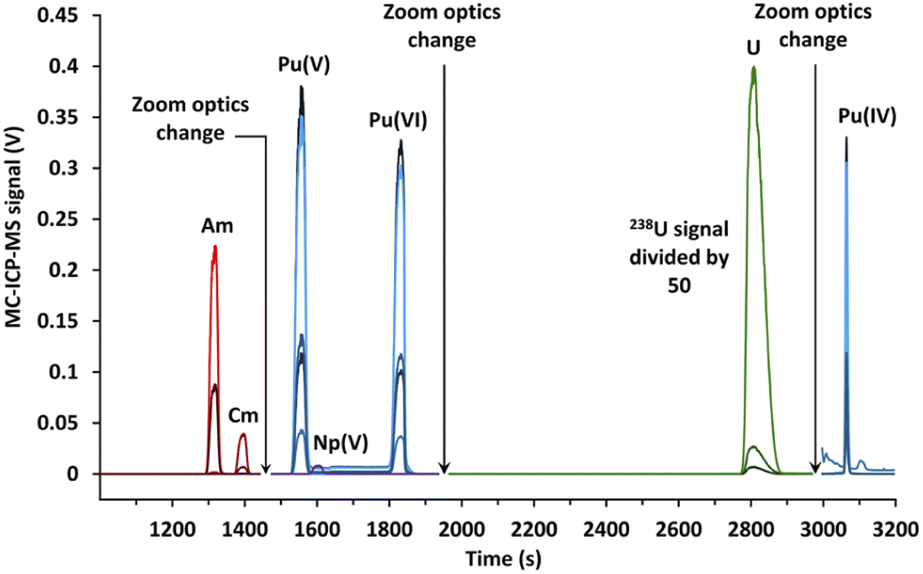 | ||
| Fig. 6 Electropherogram obtained by CE-MC-ICP-MS for actinides in a spent MOX fuel sample with a 120 mmol L−1 α-HMBA electrolyte. The line breaks were caused by the change in zoom optics during the CE separation. | ||
The signal breaks observed on Fig. 6 for a migration time of 1450 and 1950 s were caused by the change in zoom optics in order to switch between the different subconfigurations. Again, two peaks of plutonium corresponding to Pu(V) and Pu(VI) were obtained. Isotope results were given for the Pu(V) peak, as opposed to Pu(VI) which was only present in some separations due to a reduction over time.
Isotope results for the actinides (U, Pu, Am, and Cm) obtained for the CE-MC-ICP-MS analyses as well as the standard deviation, the relative standard deviation, reference values, and biases from the reference values are presented in Tables 1 and 2. Furthermore, the apex signals acquired with MC-ICP-MS and the R2 found with the LRS method are also listed in Tables 1 and 2. The reference values correspond to values acquired by two-step liquid chromatography followed by TIMS or MC-ICP-MS, corrected for radioactive decay, as all isotope ratios and elemental concentrations were determined prior to the CE-MC-ICP-MS measurements.
| Isotope ratio | 234U/238U | 235U/238U | 236U/238U |
|---|---|---|---|
| Injection 1 | 0.000338 | 0.00134 | 0.000353 |
| Injection 2 | 0.000339 | 0.00137 | 0.000354 |
| Injection 3 | 0.000338 | 0.00132 | 0.000353 |
| Injection 4 | 0.000339 | 0.00134 | 0.000353 |
| Average value | 0.000339 | 0.00134 | 0.000353 |
| Standard deviation (1σ) | 0.000001 | 0.00002 | 0.000001 |
| RSD (%) | 0.20 | 1.4 | 0.22 |
| Reference value ± uc, k = 1 | 0.000335 ± 0.000002 | 0.001320 ± 0.000002 | 0.000346 ± 0.000001 |
| Relative difference (%) | 1.1 | 1.7 | 2.2 |
| Injected quantity (calculated) | 234U – 2 pg, 238U – 9.6 ng | 12 pg | 3 pg |
| MC-ICP-MS apex signal | 234U – 8 mV, 238U – 24 V | 33 mV | 9 mV |
| R 2 (LRS) | 0.998 | 0.9996 | 0.998 |
| Isotope ratio | 238Pu/239Pu | 240Pu/239Pu | 241Pu/239Pu | 242Pu/239Pu | 243Am/241Am | 245Cm/244Cm |
|---|---|---|---|---|---|---|
| Injection 1 | 0.11375 | 0.92021 | 0.30877 | 0.35481 | 0.3882 | 0.1721 |
| Injection 2 | 0.11371 | 0.92061 | 0.30886 | 0.35516 | 0.3885 | 0.1720 |
| Injection 3 | 0.11379 | 0.92023 | 0.30870 | 0.35477 | 0.3887 | 0.1707 |
| Injection 4 | 0.11373 | 0.92037 | 0.30876 | 0.35505 | 0.3879 | 0.1725 |
| Injection 5 | 0.11372 | 0.92035 | 0.30868 | 0.35488 | 0.3877 | 0.1723 |
| Average value | 0.11374 | 0.92035 | 0.30875 | 0.35494 | 0.3882 | 0.1719 |
| Standard deviation (1σ) | 0.00003 | 0.00016 | 0.00007 | 0.00017 | 0.0004 | 0.0008 |
| RSD (%) | 0.03 | 0.018 | 0.023 | 0.05 | 0.11 | 0.42 |
| Reference value ± uc, k = 1 | 0.11356 ± 0.00019 | 0.91667 ± 0.00091 | 0.30898 ± 0.00031 | 0.35427 ± 0.00035 | 0.3961 ± 0.0007 | 0.1717 ± 0.0005 |
| Relative difference (%) | 0.16 | 0.4 | −0.08 | 0.19 | −2.00 | 0.12 |
| Injected quantity (calculated) | 238Pu – 30 pg, 239Pu – 260 pg | 240 pg | 80 pg | 95 pg | 241Am – 58 pg, 243Am – 23 pg | 244Cm – 10 pg, 245Cm – 1.8 pg |
| MC-ICP-MS apex signal | 238Pu – 90 mV, 239Pu – 789 mV | 730 mV | 246 mV | 284 mV | 241Am – 318 mV, 243Am – 125 mV | 244Cm – 55 mV, 245Cm – 9 mV |
| R 2 (LRS) | 0.99998 | 0.9999992 | 0.999996 | 0.999997 | 0.999992 | 0.9992 |
During data acquisition, it was quickly identified that isotope ratios measured for the uranium present in the spent MOX fuel sample had relative standard deviations in the per-cent range and that they differed significantly from the reference value (more than 1% of relative difference, see Table 1). For the uranium isotope ratios, relative standard deviations were comprised between 0.20% and 1.4% and relative differences from the reference values were comprised between 1.1% and 2.2%. It was identified that the inlet of the CE system was contaminated by a previous uranium sample, enriched in 235U.33 This contamination only affected uranium isotope ratios. The origin of this sample carryover has since been removed.
For plutonium, the values of relative standard deviations presented in Table 2 for the isotope ratios of the spent MOX fuel sample ranged from 0.018% for the 240Pu/239Pu ratio to 0.05% in the case of the 242Pu/239Pu isotope ratio. For the 243Am/241Am and 245Cm/244Cm isotope ratios, relative standard deviations were of 0.11% and 0.42%, respectively. These values were all in the per-mil level, corresponding to the repeatability for the five injections, despite the quantity of Pu, Am, and Cm isotopes being in the pg range.
Biases from reference values presented in Table 2 ranged from −0.08% to 0.4% for plutonium. The relative difference with the reference value was in the per-mil range for these ratios. For americium, a bias of 2% was observed. The origin of this bias has yet to be identified, but is believed to be caused by a shift in zoom optics during the analytical session. For curium, the bias with the reference value was 0.12%, in the per-mil range.
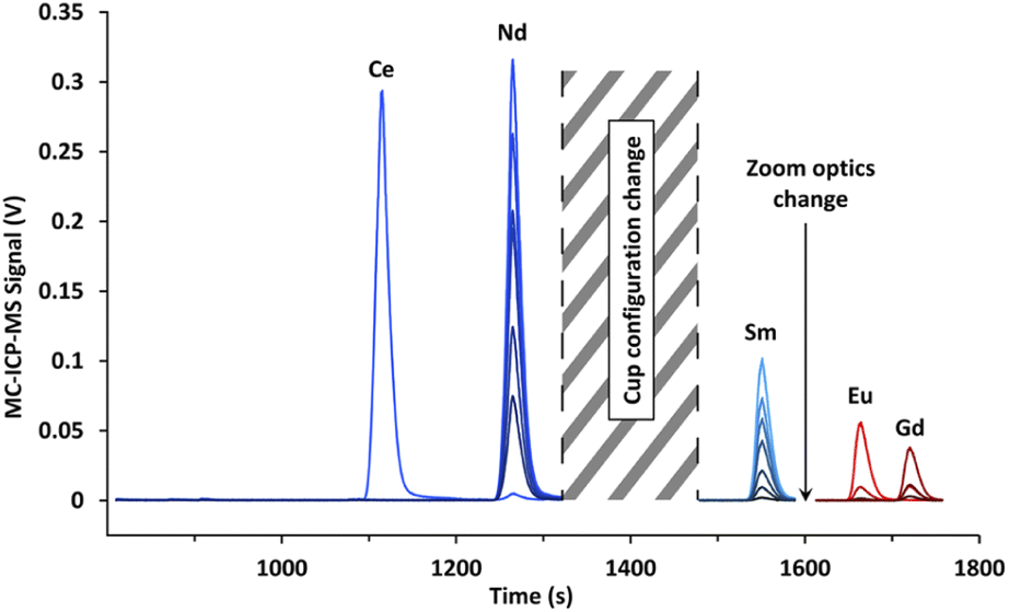 | ||
| Fig. 7 Electropherogram obtained by CE-MC-ICP-MS for lanthanide fission products in a spent MOX fuel sample with a 120 mmol L−1 α-HMBA electrolyte. The signal break between 1300 and 1500 s was caused by a cup configuration change, while the shorter signal break between 1575 and 1625 s was due to a modification in zoom optics. | ||
The MC-ICP-MS signal breaks visible on Fig. 7 were the result of a change of cup configuration between the migration of Nd and Sm as well as a modification of zoom optics between the migration of Sm and Eu.
Isotope results for lanthanide fission products (Nd, Sm, Eu, and Gd) obtained for the six CE-MC-ICP-MS analyses as well as the standard deviation, relative standard deviation, reference values and biases from the reference values are presented in Tables 3–5. Furthermore, the apex signals obtained with MC-ICP-MS and the R2 found with the LRS method are also listed in Tables 3–5.
| Isotope ratio | 143Nd/145Nd | 144Nd/145Nd | 146Nd/145Nd | 148Nd/145Nd | 150Nd/145Nd |
|---|---|---|---|---|---|
| Injection 1 | 1.3725 | 1.6367 | 1.0575 | 0.6225 | 0.3689 |
| Injection 2 | 1.3723 | 1.6356 | 1.0564 | 0.6223 | 0.3695 |
| Injection 3 | 1.3731 | 1.6358 | 1.0563 | 0.6220 | 0.3682 |
| Injection 4 | 1.3732 | 1.6360 | 1.0561 | 0.6217 | 0.3679 |
| Injection 5 | 1.3730 | 1.6357 | 1.0560 | 0.6217 | 0.3681 |
| Injection 6 | 1.3727 | 1.6355 | 1.0559 | 0.6218 | 0.3681 |
| Average value | 1.3728 | 1.6359 | 1.0564 | 0.6220 | 0.3685 |
| Standard deviation (1σ) | 0.0004 | 0.0005 | 0.0007 | 0.0004 | 0.0007 |
| RSD (%) | 0.026 | 0.025 | 0.06 | 0.06 | 0.17 |
| Reference value ± uc, k = 1 | 1.3766 ± 0.0021 | — | 1.0549 ± 0.0016 | 0.6199 ± 0.0010 | 0.3663 ± 0.0007 |
| Relative difference (%) | −0.28 | — | 0.14 | 0.34 | 0.60 |
| Injected quantity (calculated) | 143Nd – 14 pg, 145Nd – 11 pg | 17 pg | 11 pg | 7 pg | 4 pg |
| MC-ICP-MS apex signal | 143Nd – 364 mV, 145Nd – 270 mV | 438 mV | 288 mV | 173 mV | 104 mV |
| R 2 (LRS) | 0.99998 | 0.999991 | 0.999991 | 0.99998 | 0.99994 |
| Isotope ratio | 147Sm/150Sm | 148Sm/150Sm | 149Sm/150Sm | 151Sm/150Sm | 152Sm/150Sm | 154Sm/150Sm |
|---|---|---|---|---|---|---|
| Injection 1 | 0.74198 | 0.58501 | 0.01953 | 0.0946 | 0.41268 | 0.20550 |
| Injection 2 | 0.74169 | 0.58454 | 0.01942 | 0.0944 | 0.41263 | 0.20590 |
| Injection 3 | 0.74162 | 0.58462 | 0.01947 | 0.0949 | 0.41273 | 0.20546 |
| Injection 4 | 0.74210 | 0.58466 | 0.01934 | 0.0948 | 0.41281 | 0.20558 |
| Injection 5 | 0.74167 | 0.58484 | 0.01940 | 0.0949 | 0.41255 | 0.20535 |
| Injection 6 | 0.74174 | 0.58457 | 0.01921 | 0.0951 | 0.41297 | 0.20560 |
| Average value | 0.74180 | 0.58471 | 0.01939 | 0.0948 | 0.41273 | 0.20556 |
| Standard deviation (1σ) | 0.00020 | 0.00019 | 0.00012 | 0.0003 | 0.00015 | 0.00019 |
| RSD (%) | 0.03 | 0.04 | 0.6 | 0.4 | 0.04 | 0.1 |
| Reference value ± uc,k = 1 | — | 0.5846 ± 0.0012 | 0.0191 ± 0.0001 | 0.0951 ± 0.0002 | 0.4123 ± 0.0008 | 0.2056 ± 0.0004 |
| Relative difference (%) | — | 0.02 | 1.6 | −0.4 | 0.1 | −0.03 |
| Injected quantity (calculated) | 147Sm – 3.5 pg, 150Sm – 5.7 pg | 3.3 pg | 110 fg | 550 fg | 2.4 pg | 1.2 pg |
| MC-ICP-MS apex signal | 147Sm – 109 mV, 150Sm – 151 mV | 87 mV | 3 mV | 15 mV | 64 mV | 33 mV |
| R 2 (LRS) | 0.99995 | 0.99997 | 0.98 | 0.9995 | 0.99996 | 0.9998 |
| Isotope ratio | 154Eu/153Eu | 155Eu/153Eu | 154Gd/158Gd | 155Gd/158Gd | 156Gd/158Gd |
|---|---|---|---|---|---|
| Injection 1 | 0.17098 | 0.02439 | 0.9159 | 0.2709 | 3.422 |
| Injection 2 | 0.17100 | 0.02484 | 0.9145 | 0.2699 | 3.416 |
| Injection 3 | 0.17034 | 0.02476 | 0.9158 | 0.2731 | 3.414 |
| Injection 4 | 0.17079 | 0.02470 | 0.9145 | 0.2710 | 3.421 |
| Injection 5 | 0.17061 | 0.02472 | 0.9174 | 0.2709 | 3.413 |
| Injection 6 | 0.17092 | 0.02457 | 0.9197 | 0.2714 | 3.415 |
| Average value | 0.17077 | 0.02466 | 0.9163 | 0.2712 | 3.417 |
| Standard deviation (1σ) | 0.00026 | 0.00017 | 0.0021 | 0.0011 | 0.004 |
| RSD (%) | 0.2 | 0.7 | 0.3 | 0.4 | 0.2 |
| Reference value ± uc, k = 1 | 0.1710 ± 0.0004 | 0.0247 ± 0.0001 | 0.9114 ± 0.0014 | 0.2693 ± 0.0007 | 3.421 ± 0.004 |
| Relative difference (%) | −0.2 | −0.4 | 0.6 | 0.8 | −0.2 |
| Injected quantity (calculated) | 154Eu – 490 fg, 153Eu – 2.8 pg | 71 fg | 154Gd – 563 fg, 158Gd – 634 fg | 167 fg | 2.2 pg |
| MC-ICP-MS apex signal | 154Eu – 15 mV, 153Eu – 86 mV | 2 mV | 154Gd – 16 mV, 158Gd – 18 mV | 5 mV | 58 mV |
| R 2 (LRS) | 0.9995 | 0.98 | 0.9990 | 0.995 | 0.9995 |
For neodymium, the values in Table 3 of the relative standard deviations for the isotope ratios of the spent MOX fuel sample ranged from 0.03% to 0.17%.
Biases from reference values presented in Table 3 ranged from 0.14% to 0.6% for the neodymium isotope ratios. A >1% bias was observed for the 144Nd/145Nd isotope ratio and was caused by the decay of the short-lived 144Ce, unaccounted for in the decay calculations as this isotope was not measured when the reference values were determined.
In the case of samarium, the relative standard deviations ranged from 0.03% to 0.6%. Biases from reference values were between 0.02% and 1.6%. For both RSD and bias, the highest values were obtained for the 149Sm/150Sm ratio. The increase in RSD and relative difference (as compared to the other values) for the 149Sm/150Sm ratio was caused by the lack of signal for 149Sm, with only 3 mV at the apex of the peak.
For europium and gadolinium, the relative standard deviations ranged from 0.2% to 0.7% and the relative differences were between 0.2% and −0.8%.
In all injections performed for actinides and lanthanides, the relative standard deviations for the isotope ratios were between 0.01% and 0.1% when the MC-ICP-MS signal was on the order of 100 mV or more. For an MC-ICP-MS signal from 2 mV to 100 mV, the relative standard deviations ranged from 0.01% to 1%. This demonstrated the robustness of the LRS data treatment method to measure isotope ratios, even when the MC-ICP-MS signal was only a few mV.
The CE-MC-ICP-MS hyphenation therefore allowed the determination of 16 isotope ratios for lanthanide fission products in one CE injection and of 9 isotope ratios for actinides in another CE injection. For all of these isotope ratios, the relative standard deviation was comprised between 0.01% and 1.4%. Furthermore, the injected quantity was in the pg range or less for all isotopes (except 238U) and even in the fg range for isotopes such as 149Sm or 151Sm.
Conclusions
A CE-ICP-MS method for the separation and measurement of elements of interest contained in a spent MOX fuel sample was developed. For the proof of concept, isotope ratios were determined for U, Pu, Am, Cm, Nd, Sm, Eu, and Gd in two CE-MC-ICP-MS injections with identical separation conditions. The precision and trueness obtained for the isotope ratios were in the per-mil range when 1 pg or more of the isotope was injected (except for uranium due to sample carry-over) and in the per-cent range when less than 1 pg of the isotope was injected.The precision and trueness obtained were therefore comparable to the ones found with offline chromatographic methods. With CE-MC-ICP-MS, sample quantities were in the ng range for uranium and in the pg range or less for all other elements while waste volume production was in the tens-of-μL range. This can be compared with sample quantities in the μg range and waste volume production in the tens or hundreds of mL range with offline chromatographic methods.
The CE-MC-ICP-MS method developed in this work is directly applicable to the precise determination of elemental concentrations in spent nuclear fuel samples with the use of isotope dilution.
The Ln/An separation method using α-HMBA or α-HIBA developed during the course of this research can be applied to other samples originating from the nuclear fuel cycle but also to nuclear forensics or environmental samples. In these cases, preconcentration methods or alternative detectors such as Secondary Electron Multipliers (SEMs) could be used to increase the method's sensitivity. More generally, the hyphenation of CE with ICP-MS is a powerful tool for speciation studies, in order to assign peaks to oxidation states or even to determine redox kinetics.
Conflicts of interest
There are no conflicts to declare.Acknowledgements
The authors thank the PRATA CEA project for funding, Pascal Reiller and Thomas Vercouter for fruitful discussions on plutonium chemistry, Laurent Vio, Benoît Martelat, Charles Evette, and Audrey Arroyo-Nava for discussions on CE separations, and Julie Stevenin for discussions on mass bias correction.Notes and references
- I. Gauld, J. Giaquinto, J. Delashmitt, J. Hu, G. Ilas, T. Haverlock and C. Romano, Ann. Nucl. Energy, 2016, 87, 267–281 CrossRef CAS.
- L. San-Felice, R. Eschbach and P. Bourdot, Nucl. Technol., 2013, 184, 217–232 CrossRef CAS.
- D. Bernard and A. Santamarina, Ann. Nucl. Energy, 2016, 87, 21–33 CrossRef CAS.
- S. Bürger, J. Vogl, U. Kloetzli, L. Nunes and M. Lavelle, Sector Field Mass Spectrometry for Elemental and Isotopic Analysis, Royal Society of Chemistry, 2014, pp. 381–438 Search PubMed.
- N. Jakubowski, M. Horsky, P. H. Roos, F. Vanhaecke and T. Prohaska, Sector Field Mass Spectrometry for Elemental and Isotopic Analysis, Royal Society of Chemistry, 2014, pp. 208–318 Search PubMed.
- K. G. Heumann, Mass Spectrom. Rev., 1992, 11, 41–67 CrossRef CAS.
- A. Gourgiotis, M. Granet, H. Isnard, A. Nonell, C. Gautier, G. Stadelmann, M. Aubert, D. Durand, S. Legand and F. Chartier, J. Anal. At. Spectrom., 2010, 25, 1939 RSC.
- J. Moureau, M. Granet, F. Chartier, G. Favre, H. Isnard and A. Nonell, J. Anal. At. Spectrom., 2008, 23, 1538 RSC.
- F. Guéguen, A. Nonell, M. Granet, G. Favre, H. Isnard and F. Chartier, J. Anal. At. Spectrom., 2010, 25, 201–205 RSC.
- F. Chartier, M. Aubert and M. Pilier, Fresenius. J. Anal. Chem., 1999, 364, 320–327 CrossRef CAS.
- A. Quemet, M. Angenieux and A. Ruas, J. Anal. At. Spectrom., 2021, 36, 1758–1767 RSC.
- F. Goutelard, C. Caussignac, R. Brennetot, G. Stadelmann and C. Gautier, J. Radioanal. Nucl. Chem., 2009, 282, 669–675 CrossRef CAS.
- F. Guéguen, H. Isnard, A. Nonell, L. Vio, T. Vercouter and F. Chartier, J. Anal. At. Spectrom., 2015, 30, 443–452 RSC.
- H. Smith and D. C. Hoffman, J. Inorg. Nucl. Chem., 1956, 3, 243–247 CrossRef CAS.
- T. Nishi and I. Fujiwara, J. At. Energy Soc. Jpn., 1964, 6, 15–20 CrossRef CAS.
- G. Choppin and J. Chopoorian, J. Inorg. Nucl. Chem., 1961, 22, 97–113 CrossRef CAS.
- I. Günther-Leopold, J. K. Waldis, B. Wernli and Z. Kopajtic, Int. J. Mass Spectrom., 2005, 242, 197–202 CrossRef.
- I. Günther-Leopold, N. Kivel, J. K. Waldis and B. Wernli, Anal. Bioanal. Chem., 2007, 390, 503–510 CrossRef.
- F. Guéguen, A. Nonell, H. Isnard, L. Vio and F. Chartier, Talanta, 2017, 162, 278–284 CrossRef PubMed.
- J. I. Garcia Alonso, F. Sena, P. Arbore, M. Betti and L. Koch, J. Anal. At. Spectrom., 1995, 10, 381–393 RSC.
- R. Kuhn and S. Hoffstetter-Kuhn, Capillary Electrophoresis: Principles and Practice, Springer, Berlin, Heidelberg, 1993 Search PubMed.
- L. Vio, G. Crétier, F. Chartier, V. Geertsen, A. Gourgiotis, H. Isnard, P. Morin and J.-L. Rocca, J. Anal. At. Spectrom., 2012, 27, 850 RSC.
- J. Petit, V. Geertsen, C. Beaucaire and M. Stambouli, J. Chromatogr. A, 2009, 1216, 4113–4120 CrossRef CAS.
- D. Schaumloffel and A. Prange, Fresenius. J. Anal. Chem., 1999, 364, 452–456 CrossRef CAS.
- W. Kraak and G. Wals, J. Chromatogr. A, 1965, 20, 197–201 CrossRef CAS.
- J. A. Day, J. A. Caruso, J. S. Becker and H.-J. Dietze, J. Anal. At. Spectrom., 2000, 15, 1343–1348 RSC.
- A. Pitois, L. A. de Las Heras and M. Betti, Int. J. Mass Spectrom., 2008, 270, 118–126 CrossRef CAS.
- C. Ambard, A. Delorme, N. Baglan, J. Aupiais, F. Pointurier and C. Madic, Radiochim. Acta, 2005, 93, 665–673 CrossRef CAS.
- B. Kuczewski, C. M. Marquardt, A. Seibert, H. Geckeis, J. V. Kratz and N. Trautmann, Anal. Chem., 2003, 75, 6769–6774 CrossRef CAS PubMed.
- S. Bürger, N. L. Banik, R. A. Buda, J. V. Kratz, B. Kuczewski and N. Trautmann, Radiochim. Acta, 2007, 95, 433–438 CrossRef.
- C. Willberger, S. Amayri, V. Häußler, R. Scholze and T. Reich, Anal. Chem., 2019, 91, 11537–11543 CrossRef CAS PubMed.
- B. Martelat, H. Isnard, L. Vio, E. Dupuis, T. Cornet, A. Nonell and F. Chartier, Anal. Chem., 2018, 90, 8622–8628 CrossRef CAS PubMed.
- E. Dupuis, H. Isnard, C. Evette and F. Chartier, Talanta, 2020, 219, 121345 CrossRef CAS.
- M. Crozet and C. Rivier, J. Radioanal. Nucl. Chem., 2014, 302, 103–115 CrossRef CAS.
- L. S. Ettre, Pure Appl. Chem., 1993, 65, 819–872 CrossRef CAS.
- E. G. Yanes and N. J. Miller-Ihli, Spectrochim. Acta, Part B, 2005, 60, 555–561 CrossRef.
- J. Fietzke, V. Liebetrau, D. Günther, K. Gürs, K. Hametner, K. Zumholz, T. H. Hansteen and A. Eisenhauer, J. Anal. At. Spectrom., 2008, 23, 955–961 RSC.
- G. Craig, Z. Hu, A. Zhang, N. S. Lloyd, C. Bouman and J. Schwieters, Thermo Fish. Sci. Bremen Technical Note, 2017, 1–8 Search PubMed.
- H. Isnard, M. Granet, C. Caussignac, E. Ducarme, A. Nonell, B. Tran and F. Chartier, Spectrochim. Acta, Part B, 2009, 64, 1280–1286 CrossRef.
- M.-M. Bé, V. Chisté, C. Dulieu, X. Mougeot, E. Browne, V. Chechev, N. Kuzmenko, F. Kondev, A. Luca, M. Galán, A. Nichols, A. Arinc and X. Huang, Monographie BIPM – Table of Radionuclides, 2010, vol. 5, pp. 133–228 Search PubMed.
- L. Vio, B. Martelat, H. Isnard, A. Nonell and F. Chartier, Talanta, 2018, 176, 582–588 CrossRef CAS PubMed.
- C. N. Maréchal, P. Télouk and F. Albarède, Chem. Geol., 1999, 156, 251–273 CrossRef.
- J. Dubois, G. Retali and J. Cesario, Int. J. Mass Spectrom. Ion Processes, 1992, 120, 163–177 CrossRef CAS.
- N. M. Raut, P. Jaison and S. K. Aggarwal, J. Chromatogr. A, 2002, 959, 163–172 CrossRef CAS.
- The Chemistry of the Actinide and Transactinide Elements, ed. L. R. Morss, N. M. Edelstein and J. Fuger, Springer, Netherlands, 2011 Search PubMed.
- J. Cleveland, The Chemistry of Plutonium, American Nuclear Society, 2nd edn, 1979 Search PubMed.
- R. D. Shannon, Acta Crystallogr., Sect. A: Cryst. Phys., Diffr., Theor. Gen. Crystallogr., 1976, 32, 751–767 CrossRef.
Footnote |
| † Electronic supplementary information (ESI) available. See https://doi.org/10.1039/d2ja00265e |
| This journal is © The Royal Society of Chemistry 2022 |