
 Open Access Article
 This Open Access Article is licensed under a Creative Commons Attribution-Non Commercial 3.0 Unported Licence
The sensitive determination of Ag, Pb and Tl as well as reduction of spectral interferences in a hanging drop cathode atmospheric pressure glow discharge excitation microsource equipped with a Dove prism system
Krzysztof
Swiderski
 *,
Krzysztof
Greda
,
Pawel
Pohl
and
Piotr
Jamroz
*
*,
Krzysztof
Greda
,
Pawel
Pohl
and
Piotr
Jamroz
*
Department of Analytical Chemistry and Chemical Metallurgy, Faculty of Chemistry, Wroclaw University of Science and Technology, Wyb. Wyspianskiego 27, 50-370 Wroclaw, Poland. E-mail: piotr.jamroz@pwr.edu.pl; krzysztof.swiderski@pwr.edu.pl; Fax: +48-71-320-3807; Tel: +48-71-320-3807
First published on 31st January 2022
Abstract
The application of hanging drop cathode (HDC) atmospheric pressure glow discharge (APGD) coupled with a Dove prism (DP) as an efficient excitation microsource for optical emission spectrometry (OES) was evaluated in details. The design of experiment (DoE) approach was applied to optimize the operating conditions, i.e., the discharge current, the graphite tube diameter, and the HNO3 concentration, of this excitation source. The effect of the addition of low molecular weight organic compounds (LMWOCs) on the intensity of the analytical lines of Ag, Ca, Cd, Hg, Mg, Mn, Pb and Tl was evaluated, and the most beneficial results were obtained for 8% (m/m) formic acid. Using a Dove prism, the 2-D spatial distribution profiles of the emission lines of the selected elements (Ag, Ca, Cd, Hg, Mg, Mn, Pb and Tl) and the background species (H, O I, O II, N2, OH, and NO) were obtained. In the developed system, the enhancement of the Ag, Pb and Tl atomic emission lines was the most spectacular and resulted in the improved limits of detection (LODs) of these elements, being 0.54, 14 and 2.2 μg L−1, respectively. For this reason, this method was used for the sensitive determination of these analytes. The trueness and the precision of the developed method were verified by the analysis of a certified reference material (CRM) of tea leaves (INCT-TL-1).
Introduction
Atmospheric pressure glow discharge (APGD) has been well known as an efficient excitation source in optical emission spectrometry (OES) since 1993.1 In that time, Cserfalvi and Mezei presented a device in which an electrolyte solution was polarized as the cathode, and hence the discharge was generated in a gap between a metallic anode and this solution1 directly in the atmosphere of the surrounding air. This new excitation source allowed the determination of the elements in sample solutions with no need of any carrier or plasma gases and sample introduction systems such as a nebulizer along with a spray chamber.1,2 This made the APGD system, from the beginning, an interesting alternative for commercially available bulky optical emission spectrometers based on inductively coupled plasma (ICP) or microwave induced plasma (MIP).2 Another advantage of the presented device was its small size, giving a real chance for the development of portable instruments for the trace element analysis of various samples.1–3The newest APGD systems can obtain the limits of detection (LODs) of various elements comparable to or even better than those offered by commercially available ICP spectrometers.1,2 In addition, the past decades of research devoted to APGD brought a much better understanding of the processes occurring at the plasma–liquid interface and being responsible for the transport of analytes from the delivered solutions into the discharge column, in addition to the atomization and excitation processes occurring therein. To date, numerous parameters affecting the analytical performance of APGD-OES methods were investigated, including the type of acid used for acidification of the delivered solutions,1,4 pH of these solutions,1,5,6 the concentration of the added ionic and non-ionic surfactants7 or low molecular weight organic compounds,5,8,9 and the discharge current,6,10 as well as the polarization of the liquid electrodes.11 All these parameters were related to the discharge itself or to the analyzed sample solutions.
Unfortunately, there was very little interest in the optimization of the imaging of the discharge on the entrance slit of the spectrometer because the interelectrode gap was overwhelmingly 1![[thin space (1/6-em)]](https://www.rsc.org/images/entities/char_2009.gif) :1 imaged using appropriate focusing lenses.1 Since APGD operated in contact with flowing solutions is rather non-uniform plasma, the spatially resolved acquisition may influence the analytical response of this excitation source, as reported.12,13 Therefore, an interesting modification of the optical system for APGD can be the application of a Dove prism (DP), which allows the rotation of the discharge image and influences the measured signals.
:1 imaged using appropriate focusing lenses.1 Since APGD operated in contact with flowing solutions is rather non-uniform plasma, the spatially resolved acquisition may influence the analytical response of this excitation source, as reported.12,13 Therefore, an interesting modification of the optical system for APGD can be the application of a Dove prism (DP), which allows the rotation of the discharge image and influences the measured signals.
In this work, the application of a newly developed hanging drop cathode atmospheric pressure glow discharge (HDC-APGD) system12 along with the OES detection, realized by a CCD imaging spectrometer and a DP, is presented. A rotation of the discharge image by 90° was established to reduce the intensity of the background species and increase the analytical signals of the studied elements. This effect led to a significant improvement of the LODs of the elements, particularly of those for which the analytical lines are observed in the vicinity of the OH, NO and N2 molecular bands. Using the design of experiments (DoE) approach, which involves the change of several parameters at the same time due to the Box–Behken response surface design, the discharge current, the graphite tube (to deliver the solutions) diameter, and the HNO3 concentration (to acidify these solutions) were optimized. Additionally, the influence of low molecular weight organic compounds (LMWOCs) added to the sample solutions was evaluated. Using the DP, 2-D spatial distribution maps of the analytical lines of the selected elements and the background species were obtained. Finally, the application of the developed method in the trace analysis (Ag, Pb and Tl) of a certified reference material (CRM) of tea is presented.
Experimental
Instrumentation
The experimental setup of the HDC-APGD system with the OES detection is presented in Fig. 1. The microplasma was generated between an upper hanging drop cathode and a lower tapered tungsten pin anode (d = 3.0 mm). A liquid drop was formed on the edge of a quartz tube (i.d. 1.0 mm; o.d. 3.0 mm) inserted into a graphite tube (i.d. 3.0 mm; o.d. 6.0 mm). The edge of the quartz tube was 1 mm below the edge of the graphite tube. The distance between the edge of the quartz tube of the HDC compartment and the tungsten pin anode was 2.5 mm to provide the self-initiation of the discharge. The solutions were introduced into the plasma zone by using a high precision 3-channel, 12-roller ISM4312 Reglo micropump (Ismatec, USA). The solution flow rate (i.e., 1.1 mL min−1) was set to provide the self-sustenance of the liquid drop. Hence, a balance between the solution uptake rate and the evaporation rate was achieved. A discharge current of 65 mA was provided by a DP50H-024PH high voltage (HV) power supply (DCS-Electronic, Germany). To stabilize the discharge, a 10 kΩ, 30 Watt ballast high-power resistor (Tyco, USA) was connected in series. | ||
| Fig. 1 A schematic representation of the HDC-APGD-DP-OES experimental system. | ||
The radiation emitted by HDC-APGD was imaged 1:1 using an achromatic quartz lens (f = 78.5 mm) on the entrance slit (10 μm) of a Shamrock SR-500i (Andor, UK) spectrometer, equipped with a Newton DU-920P-OE (Andor, UK) CCD camera and two holographic gratings (1800 and 1200 groves per mm). The interelectrode gap was imaged vertically and horizontally on the entrance slit of the spectrometer. A quartz DP (Lambda Research Optics, USA), placed in a kinematic rotation mount (Thorlabs, Sweden), was applied in order to rotate the obtained image (90°) on the spectrometer entrance slit.
To handle the spectrometer and control its configurations, Solis S (Andor, UK) software was used. The intensities of the atomic emission lines and the molecular band heads were background corrected using the two-point correction method on either sides of their profiles and the baseline signal subtraction, respectively. The CCD camera was operated in a full vertical binning (FVB) mode as well as in an image mode (1024 × 255 px). In the FVB mode, the integration time was 1 s with 10 repetitions. In the case of the image mode, in order to obtain more reliable data, the integration time was set to 10 s, which was caused by the lower sensitivity of the CCD camera in this mode.
Reagents, materials and preparation of the samples
Re-distilled water and analytical grade (or better) chemical compounds were used throughout this work. The single element stock (1000 mg L−1) standard solutions of Ag, Ca, Cd, Hg, Mg, Mn, Pb and Tl were supplied by Sigma-Aldrich (Germany). All working standard solutions prepared were acidified with ACS grade 65% HNO3 from Sigma-Aldrich. The LMWOCs, i.e., ethanol (96% m/m), acetic acid (99.3% m/m), formic acid (85% m/m), and formaldehyde (40% m/m), were purchased from Avantor Performance Materials (Poland), while methanol (99.8% m/m) was provided by J.T. Baker (Netherlands). The salts of Ca, K, Mg, and Na, i.e., Ca(NO3)2·4H2O, KNO3, Mg(NO3)2·6H2O, and NaNO3, were purchased from Avantor Performance Materials (Poland) and were applied to prepare the standards solutions of these interferents in the concentration range of 10–500 mg L−1.A CRM of tea leaves (INCT-TL-1), obtained from the Institute of Nuclear Chemistry and Technology, Poland, was used to assess the trueness of the developed method. Its samples (0.5 g, n = 3) were wet digested in 10 mL of a 65% HNO3 solution (Sigma-Aldrich, Germany), using a programmable DigiPrep Jr digestion block (SCP, Canada) and appropriate quartz digestion tubes (SCP, Canada). The digestion temperature was set to 100 °C for 2 h and then increased to 120 °C for further 2 h. The resulting sample solutions of the INCT-TL-1 CRM were cooled down to room temperature and a portion of 5 mL of a 30% H2O2 solution (Avantor Performance Materials, Poland) was added to them. The heating of these sample solutions at 110 °C was continued until they were evaporated to near dryness. The residues left were dissolved in water (5 mL) and filtered through 0.45 μm nylon syringe filters. Subsequently, the prepared sample solutions were acidified with HNO3 to a concentration of 0.6 mol L−1 and formic acid was added (a final concentration of 8%, m/m). For the quantification of Ag, Pb and Tl in the INCT-TL-1 CRM samples solutions, the triplicate standard additions method was applied.
Results and discussion
The optimization by the design of experiments approach
To optimize the operating parameters of the HDC-APGD system, the DoE approach was applied based on the Box–Behnken design that enabled to provide the models of the response surfaces for the intensities of the atomic emission lines of the studied elements. This approach was previously used to assess the effect of several factors on the multi-response in different analytical and technological systems; such factor settings were selected that followed the compliance criteria for all individual responses and provided the best compromise conditions contributing to a desirable joint multi-response.14,15 The Box–Behnken design used in the present work comprised 15 runs (including 3 center points), and it was related to the number of the studied experimental factors and the combinations of their settings at 3 different levels, i.e., −1, 0 and +1. To describe the main effects, the interactions, and the curvature of the experimental factors on the measured analytical response, a quadratic model was chosen. The examined factors were: the discharge current (within the range of 35–65 mA), the concentration of HNO3 (within the range of 0.1–0.6 mol L−1) and the graphite tube diameter (within the range of 6–12 mm). The responses were the net (background corrected) intensities of the analytical emission lines, i.e., Ag I at 338.3 nm, Ca I at 422.7 nm, Cd I at 228.8 nm, Hg I at 253.7 nm, Mg I at 285.2 nm, Mn I at 279.8 nm, Pb I at 368.3 nm, and Tl I at 535.0 nm. The obtained models were reduced to remove any insignificant terms at the 90% significance level (α = 0.1). The regression equations of the reduced models are given in Table 1 along with the R-statistics obtained for them. Moreover, to better illustrate the effect of the studied experimental factors, the obtained models are depicted in Fig. 2.| Coefficients of regression equation | R-statistics of models | ||||||||||||
|---|---|---|---|---|---|---|---|---|---|---|---|---|---|
| Const | A | B | C | A 2 | B 2 | C 2 | AB | AC | BC | R 2 | R (adj) 2 | R (pred) 2 | |
| Ag | −1.25 × 10⁵ | 3.24 × 10³ | −1.67 × 10⁵ | 1.58 × 10⁴ | — | 1.07 × 10⁵ | — | 4.24 × 10³ | −3.44 × 10² | −7.24 × 10³ | 99.3 | 98.7 | 96.7 |
| Ca | −3.78 × 10⁴ | 1.30 × 10³ | −4.94 × 10⁴ | 4.81 × 10³ | −7.63 | — | −177.1 | 5.81 × 10² | −5.41 × 101 | 2.09 × 10³ | 93.9 | 85.8 | 38.5 |
| Cd | −6.10 × 10⁴ | 1.28 × 10³ | −4.41 × 10⁴ | 9.18 × 10³ | — | — | — | 3.00 × 10³ | −1.69 × 10² | −6.26 × 10³ | 94.5 | 90.3 | 83.3 |
| Hg | −2.08 × 10³ | 1.81 × 101 | −6.56 × 10³ | 5.17 × 10² | 1.52 | 5.53 × 10³ | 20.94 | 2.55 × 10² | −1.87 × 101 | −6.82 × 10² | 99.9 | 99.7 | 98.6 |
| Mg | −6.01 × 10⁵ | 1.78 × 10⁴ | −9.00 × 10⁵ | 8.14 × 10⁴ | — | 5.96 × 10³ | — | 1.83 × 10⁴ | −1.85 × 10³ | −3.06 × 10⁴ | 99.1 | 98.1 | 95.3 |
| Mn | −3.66 × 10⁴ | 1.07 × 10³ | −8.41 × 10⁴ | 6.29 × 10³ | — | 4.96 × 10⁴ | — | 1.78 × 10³ | −1.33 × 10² | −3.02 × 10³ | 98.8 | 97.5 | 91.5 |
| Pb | −2.24 × 10⁴ | 5.78 × 10² | −2.97 × 10⁴ | 3.30 × 10³ | — | — | — | 6.76 × 10² | −6.90 × 101 | — | 91.6 | 87.0 | 69.7 |
| Tl | −1.25 × 10⁵ | 6.02 × 10³ | −1.70 × 10⁵ | 9.32 × 10³ | −47.80 | — | — | 2.81 × 10³ | −1.88 × 10² | — | 83.8 | 71.7 | 31.9 |
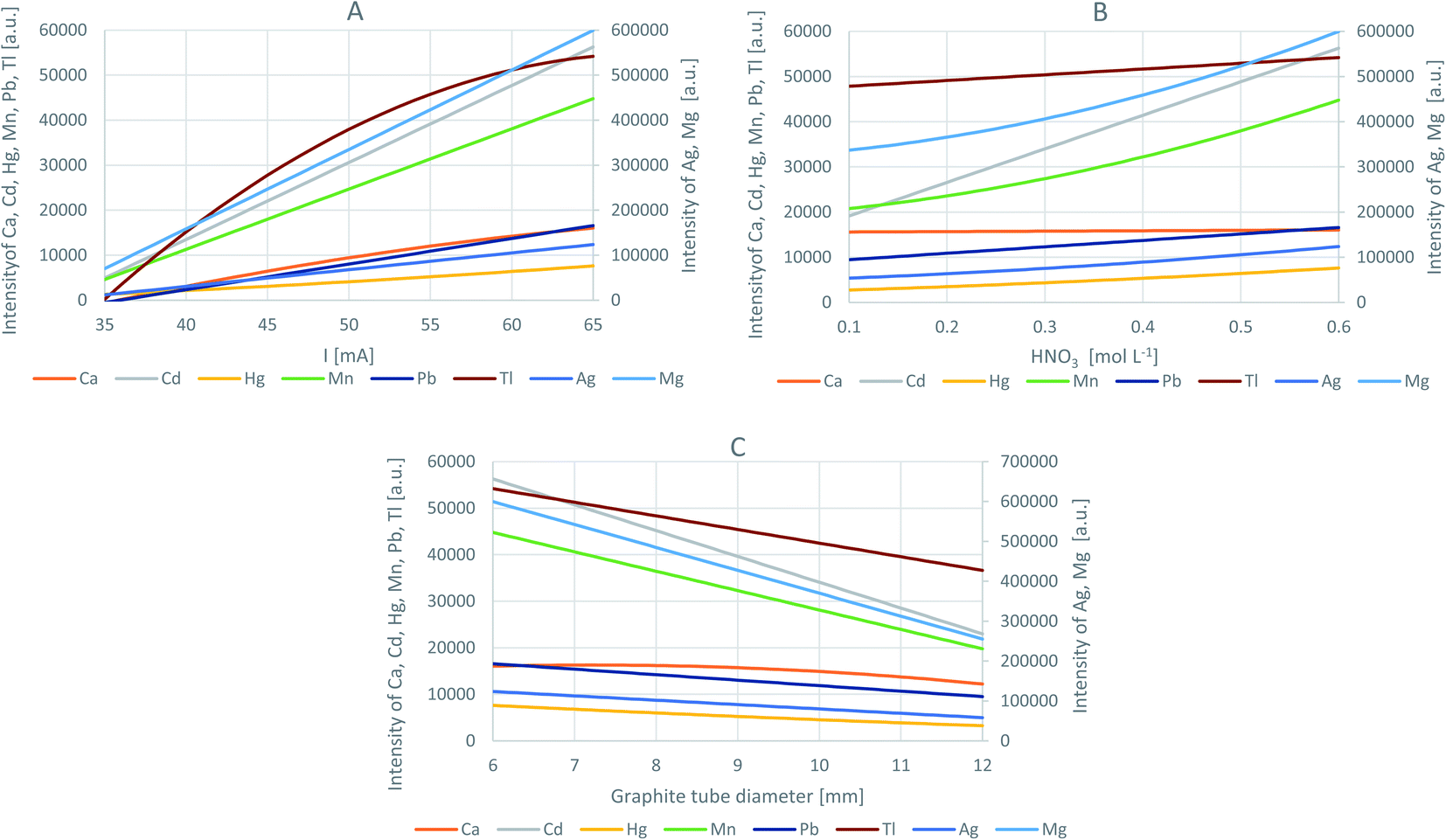 | ||
| Fig. 2 The effect of the experimental factors on the intensity of the analytical lines of the studied elements (Ag, Ca, Cd, Hg, Mg, Mn, Pb and Tl) as assessed using the optimization by the DoE approach: (A) – the discharge current at the optimal graphite tube diameter and the optimal HNO3 concentration, (B) – the HNO3 concentration at the optimal discharge current and the optimal graphite tube diameter, and (C) – the graphite tube diameter at the optimal discharge current and the optimal HNO3 concentration. | ||
Considering the coefficient of determination (R2), the closer to 100% its value, the more accurate the obtained model. As can be seen from Table 1, the models describing the effect of the studied experimental factors on the net intensities of the analytical lines of Ag, Ca, Cd, Hg, Mg, Mn, and Pb explained 92% to 100% of the measured responses, which is a very satisfying result. Only in the case of Tl, the R2 value was 84%. Nevertheless, small differences between the R2 values and the adjusted R2 (R(adj)2) values for all studied elements indicated that the obtained models were not over-fitted. Considering the predicted R2 (R(pred)2) values, the models could well predict the new responses, particularly in the case of Ag, Cd, Hg, Mg and Mn.
As could be expected, an increase in the discharge current resulted in an enhancement of the intensity of all investigated analytical lines of the studied elements (Fig. 2a). The increased discharge current certainly resulted in a more powerful discharge and a higher transport of the solution components into its phase because the sample consumption changed. In a certain period of time, when the discharge was sustained, it was possible to increase the sample uptake rate necessary to form the drop and operate the discharge. It was established that the sample uptake rate increased from 0.40 mL min−1 to 1.10 mL min−1 as the discharge current increased from 35 to 65 mA. This higher discharge power influenced not only the evaporation/sputtering rate of the solution (and the analyte transport) but also the atomization/excitation efficiency in APGD, which directly influenced the analytical signal of the elements. The enhancement of the analytical signals, caused by the increased discharge current, was also observed in other APGD systems but sustained in contact with flowing solutions.1,6
The increase of the HNO3 concentration, used for the acidification of the solutions, also enhanced the analytical signals of the studied elements, but this effect was not that strong as in the case of the discharge current (Fig. 2b). The intensity of the analytical lines of Ca and Tl was almost unchanged by the change of the solution acidity. Considering the lowest intensity of the analytical line of the studied elements acquired in the series acquired for the solutions acidified with HNO3 at concentrations changed in the range of 0.1 to 0.6 mol L−1, the most significant, almost 3-fold enhancement was observed for Cd and Hg. The change of the sample consumption was also not that significant as in the case of the discharge current; it increased from 0.70 mL min−1 (for 0.1 mol L−1 HNO3) to 1.10 mL min−1 (for 0.6 mol L−1 HNO3). For other APGD systems, an increase in the sample acidity usually led to the enhancement of the analytical signals of the studied elements and the deterioration of the discharge stability.1,6 However, it should be pointed out that in this case, when the discharge was operated in contact with flowing solutions, the concentration of HNO3 or HCl in solutions was not higher than 0.1 mol L−1. In the present system, where HDC-APGD was used and operated in contact with a solution drop, its impaired stability was observed when the HNO3 concentration exceeded 0.6 mol L−1, which indicates an increased tolerance to this acid.
The effect of the outer diameter of the graphite tube was not investigated so far for any APGD system. We hypothesized that the increase in the tube size would stabilize HDC-APGD due to the enlargement of the solution drop, causing the enhancement of the analytical performance of this system. However, as can be seen in Fig. 2c, the effect of the tube diameter was opposite to the expected one. For the system operated with large-sized tubes, a longer stabilization time was needed, the stability of HDC-APGD was decreased, and the intensity of both the atomic lines and the molecular bands was reduced.
In summary, the optimal operating conditions of the developed discharge system are as follows: the discharge current – 65 mA, the concentration of HNO3 – 0.6 mol L−1, and the graphite tube diameter – 6 mm. Under these conditions, the net intensities of the analyte emission lines were measured and compared to the values predicted by the appropriate models (see Table 2). In the case of Cd and Tl, there was an excellent agreement between the predicted and the experimentally measured values. In the case of Ag, Ca, Hg, Mg, Mn, and Pb, the measured intensities of their analytical lines were not strictly in line with the predicted values; the differences were found to be changed from −21% (Pb) to +21% (Ca). Therefore, the conditions proposed by the models were considered as fairly optimal and chosen in all further experiments.
| Element | Intensity in optimal conditions | Difference (%) | |
|---|---|---|---|
| Predicted | Measured | ||
| Ag | 1.24 × 10⁵ | 1.00 × 10⁵ | −19.4 |
| Ca | 1.60 ×10⁴ | 1.93 ×10⁴ | +20.6 |
| Cd | 5.62 × 10⁴ | 5.70 × 10⁴ | +1.4 |
| Hg | 7.61 × 10³ | 6.49 × 10³ | −14.7 |
| Mg | 6.00 × 10⁵ | 6.68 × 10⁵ | +11.3 |
| Mn | 4.48 × 10⁴ | 3.73 × 10⁴ | −16.7 |
| Pb | 1.66 × 10⁴ | 1.31 × 10⁴ | −21.1 |
| Tl | 5.42 × 10⁴ | 5.72 × 10⁴ | +5.5 |
The effect of the addition of aiding substances
To improve the analytical performance of HDC-APGD-OES, the influence of the addition of LMWOCs into the solution was examined. It is well known that small amounts of methanol, ethanol, formic acid or acetic acid in the solution of the liquid electrode in the case of different APGD systems can provide some significant changes in the emission spectra of these systems, including the increase of the analytical signals of the selected elements.5,8,12 In the case of the formation and stabilization of the hanging drop during the discharge operation, viscosity and surface tension of the solution matter and both can be changed when a certain LMWOC is added.8In this study, a series of solutions containing methanol, ethanol, formic acid, acetic acid or formaldehyde in the concentration range of 0–10% (m/m) were prepared, and the net intensities of the analytical lines of Ag, Ca, Cd, Hg, Mg, Mn, Pb and Tl were measured. The results of this experiment, expressed as enhancement factors of the acquired analytical signals of the studied elements in the solution with the added LMWOCs in reference to the analytical signals obtained for the solution without any organic additive, are given in Fig. 3. It was established that in most cases, the evaluated enhancement factors are in good agreement with those reported in the literature.1,5,9 The greatest improvement of the analyte responses was obtained in the cases of formic acid, i.e., ∼2.4–2.6-fold for Ag, Cd, Hg and Pb and formaldehyde, i.e., ∼1.2–1.4-fold for Mg, Mn and Tl. Due to the better stability of the HDC-APGD system and considering the high enhancement factors, formic acid (8%, m/m) was used in the analysis of the CRM.
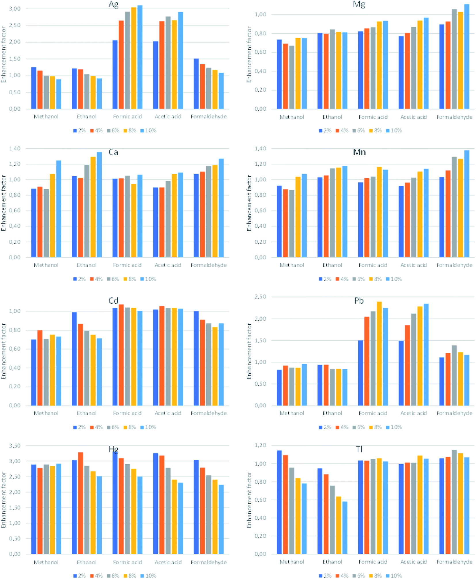 | ||
| Fig. 3 The influence of addition of the examined LMWOCs on the response of Ag, Ca, Cd, Hg, Mg, Mn, Pb and Tl. | ||
The spatial distribution of microplasma compounds
In general, when APGD is generated in contact with a solution (liquid electrode), the most intensive emission from the analyte atoms is observed in the vicinity of the solution surface10,12 (both in the case of the solution cathode and the solution anode). It was not different in the case of the presented HDC-APGD system; the most intensive emission of the analytical lines of the studied elements was observed near the solution surface, i.e., in the negative glow zone that looked like a horizontal disc right below the solution drop.Usually, the entrance slit of a spectrometer has a vertical orientation; hence, only a small part of the emitted radiation from the negative glow zone can be acquired by this spectrometer. According to the results obtained in our previous work,12 it was hypothesized that the spectrum acquisition from the whole negative glow zone length would significantly enhance the detectability of the studied elements. For this reason the interelectrode gap discharge image was rotated using a quartz DP.16,17
To efficiently use the DP, it was necessary to identify the exact position of the negative glow zone. For this purpose, 2-D maps of the intensity distribution of the analytical lines of Ag I (338.3 nm), Ca I (422.7 nm), Cd I (228.8 nm), Hg I (253.7 nm), Mg I (285.2 nm), Mn I (279.8 nm), Pb I (368.3 nm), and Tl I (535.0 nm), as well as Hβ (486.13 nm), O I (777.4 nm) and O II (441.5 nm) and the band heads of the N2 (337.4 nm), NO (247.2 nm), and OH (306.5 nm) molecules were acquired and background corrected. To move precisely the HDC-APGD image against the entrance slit of the spectrometer, the microdischarge system was placed on an optical platform equipped with two micrometer screws, allowing to position it in the horizontal and vertical directions. The abovementioned 2-D maps were obtained by vertically measuring the discharge image and the radiation emitted by it with a step of 10 μm from the central axis to the outside of the discharge volume. This step length of 10 μm was chosen as the entrance slit width of the spectrometer and covered all discharge cross-sections. The measurements were carried out using the optimal conditions selected at the previous step: the discharge current – 65 mA, the concentration of HNO3 – 0.6 mol L−1, and the graphite tube diameter – 6 mm. The results of this experiment are presented in Fig. 4 and 5. In both figures, the x-axis represents the distance from the discharge center (0), while the y-axis represents the discharge height, where 0.0 mm is the anode tip, while the solution surface is at 2.5 mm. It can be seen that HDC-APGD does not create an ideal cone with the top at the end of the anode tip but the plasma is formed partially around the end of the sharped solid electrode.
 | ||
| Fig. 4 2-D emission profiles of the analytical lines of the elements in HDC-APGD. The position of the solid anode (pin electrode) is 0 mm. | ||
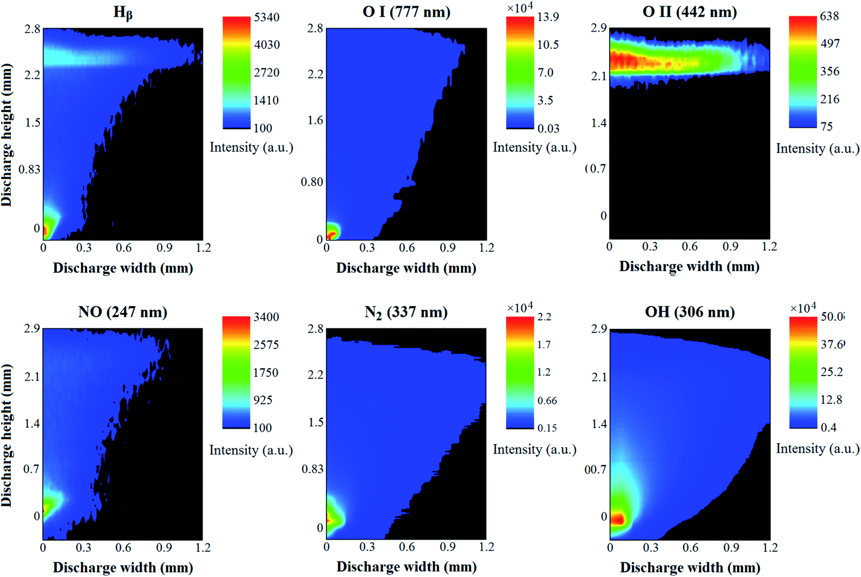 | ||
| Fig. 5 2-D emission profiles of the background species (H, O I, O II, NO, N2 and OH) in HDC-APGD. | ||
Only for few elements (Ag, Pb, and Tl), the majority of the emission from their atoms occurred in the vicinity of the liquid cathode (see Fig. 4). In the case of Ca, Mg, and Mn, the maximum of the emission of their atoms was moved toward the positive column zone. It should be noted that this phenomenon was the strongest in the case of Ca. A similar effect was observed for Cd, but in this case, the strong emission from the atoms of this element started in the negative glow zone and reached its maximum in the vicinity of the anode. In general, there was a very weak emission from the Hg atoms observed in the vicinity of the liquid cathode and in other zones of the discharge. For this element, the maximal emission from its atoms occurred (similar to the case of Cd) near the anode but was not that significantly extended to the other discharge zones, and rather concentrated in the anode glow zone. Except for O II and H, all other background species demonstrated their maximum emission in the vicinity of the anode (see Fig. 5). There was almost no emission from the N2 molecules near the cathode zone, possibly due to high evaporation and expansion rates of the water vapor, which did not allow to diffuse N2 from the air into that discharge region (Fig. 5). Similarly, as in the case of N2, the emission from O I was observed mainly in the vicinity of the anode (see Fig. 5). The emission from the NO radicals, whose presence in the APGD spectra is caused by a direct reaction between N and O from air, was also mostly observed at the end of the anode, similar to the case of N2 and O I.
To the best of our knowledge, there are no similar 2-D emission maps of different plasma (atomic and molecular) compounds available in the literature for APGD systems sustained in contact with liquids. There were few studies where the vertical or horizontal emission profiles of some plasma compounds were collected.6,12,18–20 Therefore, the results obtained in the present work are difficult to compare with them, although there are some similarities, particularly in the cases of Cd, Mg and Pb,6 Ag, Cd and Zn,12 or Pb.20
The analytical performance of the HDC-APGD system and its application to the element analysis by DP-OES
The results presented in the 2-D emission maps showed that the DP did not allow to enhance the analytical signal of all studied elements. The negative glow zone was located at about 0.1–0.3 mm below the solution surface, while the maximal intensities of the analytical lines in this zone occurred only for Ag, Pb, and Tl, and partially for Ca, Mg and Mn (in the case of these elements, the maximal intensities of their analytical lines were stretched into the positive column zone). For these elements, the enhancement of their analytical signals could be observed after applying the DP and rotating the discharge image on the entrance slit of the spectrometer. The changes in the morphology of the emission spectra in the vicinity of the analytical lines of the studied elements are shown in Fig. 6. The HDC-APGD system was placed to focus on the entrance slit of the spectrometer the radiation emitted by this excitation source from 0.2 mm below the solution drop surface. As can be seen, the intensity of the background was lowered, particularly in the vicinity of the analytical lines of Ag (by 55%), Ca (by 23%), Cd (by 32%), Hg (by 47%), Pb (by 48%) and Mg (by 50%). In addition, the background level fluctuation was also significantly reduced. At the same time, the net intensities of the analytical lines of Ag, Pb and Tl increased by 40%, 15% and 40%, respectively. Unfortunately, the net intensities of the analytical lines of other studied elements were lowered by 30% (Ca), 49% (Cd), 18% (Hg), 22% (Mg) and 31% (Mn). In this case, it was possibly caused by a different position of the discharge zones where the maximum emission from the atoms of these elements occurred. Considering the enhancement of the net intensities of the analytical lines of studied elements in addition to the lowering of the background level in the vicinity of these analytical lines and the reduction of its fluctuation, when using the DP, it was recognized that the most promising results were obtained for Ag, Pb and Tl. For these three elements, the analytical performance of the HDC-APGD-DP-OES method was assessed, and it was applied for the analysis of the CRM of tea leaves.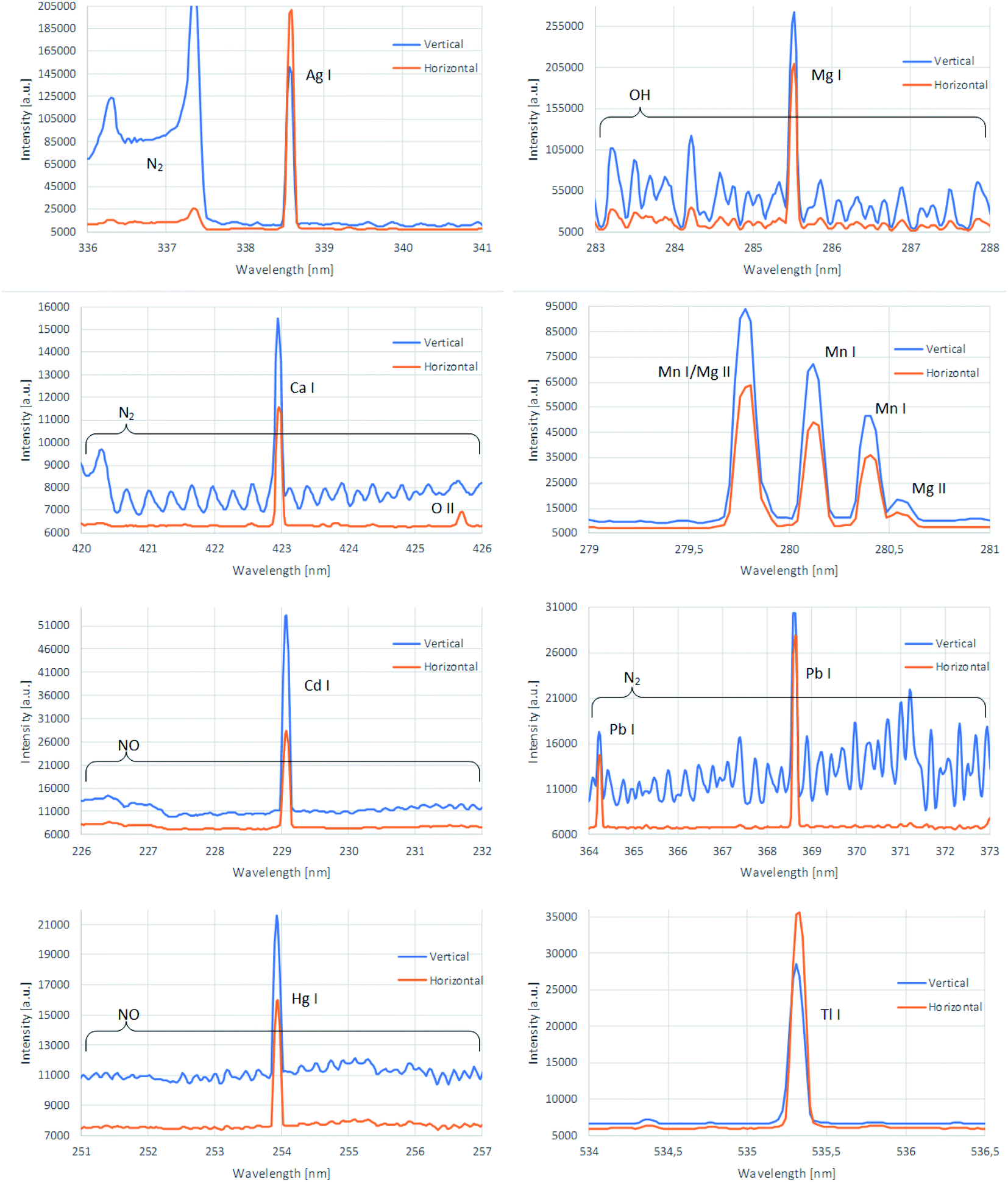 | ||
| Fig. 6 The morphology of the emission spectra of the HDC-APGD system acquired vertically (along the discharge axis) and horizontally (with the use of the Dove prism) in the vicinity of the analytical lines of Ag, Ca, Cd, Hg, Mg, Mn, Pb and Tl. | ||
A series of single-element standard solutions of Ag, Pb and Tl, acidified with 0.6 mol L−1 HNO3, were prepared, covering the concentration range from 0.010 mg L−1 to 100 mg L−1. As can be seen from Table 3, a good linearity (R2 > 0.998) was obtained up to 20, 60 and 10 mg L−1 for Ag, Pb and Tl, respectively. Based on the measurements of the respective blank solution (0.6 mol L−1 HNO3), the LODs of Ag, Pb and Tl were determined for the HDC-APGD-DP-OES system (3σ criterion, where σ was the standard deviation of the background level for a repeatedly measured n = 10), and they were 0.54 μg L−1 (Ag), 14 μg L−1 (Pb) and 2.2 μg L−1 (Tl). It is worth noting that the LODs achieved for the optical system with the DP were much better than those offered by the HDC-APGD system without the DP (see Table 4). The average precision of measurements of the intensities of the analytical lines of Ag, Pb and Tl, expressed as relative standard deviations (RSD), were 2.0%, 1.2%, and 1.1%. It should be noted that these LODs as well as RSDs were comparable to or better than those reported for other APGD systems (Table 4).
| Element | λ (nm) | Slope/103 (a.u.) | LOD (μg L−1) | URL (mg L−1) | R 2 |
|---|---|---|---|---|---|
| Ag | 338.3 | 156 | 0.54 | 20 | 0.9989 |
| Pb | 368.3 | 4.21 | 14 | 60 | 0.9998 |
| Tl | 535.0 | 22.7 | 2.2 | 10 | 0.9998 |
| Method | LOD (μg L−1) | Reference | ||
|---|---|---|---|---|
| Ag | Pb | Tl | ||
| a With the Dove prism. b Without the Dove prism. c Chemically enhanced. d SCGD – solution cathode glow discharge. e HDE – hanging drop electrode. f ac-EALD – alternating current electrolyte atmospheric liquid discharge. | ||||
| HDC-APGDa | 0.54 | 14 | 2.2 | This work |
| HDC-APGDb | 1.9 | 135 | 14 | This work |
| SCGDc,d | 0.1 | 1 | — | 9 |
| HDE-APGDe | 2.1 | — | — | 12 |
| FLC-APGD | 2 | 180 | 8 | 21 |
| ac-EALDf | 1 | 45 | — | 22 |
| SCGDd | 1 | 10 | — | 23 |
To evaluate the applicability of the developed HDC-APGD-DP-OES method in the analysis of real samples, the CRM of tea leaves (INCT-TL-1) was chosen due to the presence of certified concentrations of Pb and Tl. Since it was found that there were relatively high interferences coming from K and Na at 100 mg L−1 and higher concentrations in the case of the studied elements, the method of three standard additions (at 100, 200 and 300 μg L−1 of Ag, Pb and Tl) was applied for the calibration. Notably, the presence of Ca and Mg in the range of 10–200 mg L−1 did not result in such interferences.
The results of this analysis for Pb and Tl are given in Table 5, and in the case of Ag present in the analyzed CRM at a very low level (below 0.011 mg kg−1), the appropriate recovery is given. In the case of Pb and Tl, the developed method revealed the very good trueness, since the recoveries of the certified values were in the range 96–103%. The recovery of Ag was also quantitative (102%). All these measurements confirmed the applicability of the method in the analysis of real samples.
| Element | Found value (mg kg−1) | Certified value (mg kg−1) | Recovery (%) | |t-value|a |
|---|---|---|---|---|
| a A t-test for comparison of found and certified values was applied (n = 3, α = 0.05, and tcritical = 4.303). b The CRM was enriched with Ag. | ||||
| Ag | <0.011 | — | — | — |
| 1.02 ± 0.08 | 1.00b | 102 ± 8.0 | — | |
| Pb | 1.71 ± 0.16 | 1.78 ± 0.24 | 96.1 ± 8.9 | 0.76 |
| Tl | 0.065 ± 0.005 | 0.063 ± 0.005 | 103.2 ± 7.9 | 0.69 |
Conclusions
A new HDC-APGD-DP-OES system for the sensitive determination of Ag, Pb and Tl was developed. The use of the DoE statistical approach allowed finding the optimal operating conditions of the present excitation source system. According to the best of our knowledge, for the first time, the 2-D emission maps of various atomic and molecular species of the APGD system sustained in contact with the HDC were obtained by using a DP. The achieved spatial distribution of the plasma compounds helped in better understanding the excitation/atomization processes occurring inside the discharge column. Further work in this field, e.g., preparing similar maps when sustaining the discharge in contact with the LMWOC containing solutions, could possibly help in elucidating the mechanism of the beneficial effects of these substances, i.e., the increase of the analytical response of certain elements and the suppression of the background level and its fluctuation. Since the best results of the horizontal acquisition of the HDC-APGD spectra with DP-OES were obtained for Ag, Pb and Tl,the analytical performance assessment and the application in the analysis of real samples of the method was carried out for these elements. Low LOD values were obtained in this case, i.e., from 0.54 μg L−1 (Ag) to 14.0 μg L−1 (Pb). The linearity of the calibration curves covered 4–5 orders of magnitude. The trueness of the method was confirmed by a recovery study (Ag) and the analysis of the tea leaves CRM (Pb and Tl).Conflicts of interest
There are no conflicts to declare.Acknowledgements
This research project was funded by the National Science Center (NCN), Poland based on decision no. UMO-2018/29/N/ST4/02186.References
- P. Pohl, P. Jamroz, K. Greda, M. Gorska, A. Dzimitrowicz, M. Welna and A. Szymczycha-Madeja, Five years of innovations in development of glow discharges generated in contact with liquids for spectrochemical elemental analysis by optical emission spectrometry, Anal. Chim. Acta, 2021, 1169, 338399 CrossRef CAS PubMed.
- P. Pohl, P. Jamroz, K. Swiderski, A. Dzimitrowicz and A. Lesniewicz, Critical evaluation of recent achievements in low power glow discharge generated at atmospheric pressure between a flowing liquid cathode and a metallic anode for element analysis by optical emission spectrometry, TrAC Trends Anal. Chem., 2017, 88, 119–133 CrossRef CAS.
- T. Cserfalvi and P. Mezei, Direct solution analysis by glow discharge: electrolyte-cathode discharge spectrometry, J. Anal. At. Spectrom., 1994, 9, 345–349 RSC.
- R. Shekhar, D. Karunasagar, M. Ranjit and J. Arunachalam, Determination of elemental constituents in different matrix materials and flow injection studies by the electrolyte cathode glow discharge technique with a new design, Anal. Chem., 2009, 81, 8157–8166 CrossRef CAS PubMed.
- K. Swiderski, T. Matusiak, M. Wozinski, A. Dabrowski, L. Golonka, P. Pohl and P. Jamroz, A ceramic microchip with LDA-APGD as the excitation source for OES - a sensitive Hg detecting sensor for microsample analysis, J. Anal. At. Spectrom., 2020, 35, 1880–1886 RSC.
- M. R. Webb, F. J. Andrade, G. Gamez, R. McCrindle and G. M. Hieftje, Spectroscopic and electrical studies of a solution-cathode glow discharge, J. Anal. At. Spectrom., 2005, 20, 1218–1225 RSC.
- Z. Zhang, Z. Wang, Q. Li, H. Zou and Y. Shi, Determination of trace heavy metals in environmental and biological samples by solution cathode glow discharge-atomic emission spectrometry and addition of ionic surfactants for improved sensitivity, Talanta, 2014, 119, 613–619 CrossRef CAS PubMed.
- K. Swiderski, A. Dzimitrowicz, P. Jamroz and P. Pohl, Influence of pH and low molecular weight organic compounds in the solution on selected spectroscopic and analytical parameters of flowing liquid anode atmospheric pressure glow discharge (FLA-APGD) for optical emission spectrometric (OES) determination of Ag, Cd, and Pb, J. Anal. At. Spectrom., 2018, 33, 437–451 RSC.
- T. A. Doroski and M. R. Webb, Signal enhancement in solution-cathode glow discharge - optical emission spectrometry via low molecular weight organic compounds, Spectrochim. Acta, Part A, 2013, 88, 40–45 CrossRef CAS.
- P. Mezei and T. Cserfalvi, Charge densities in the electrolyte cathode atmospheric glow discharges (ELCAD), Eur. Phys. J. Appl. Phys., 2007, 40, 89–94 CrossRef CAS.
- K. Greda, K. Swiderski, P. Jamroz and P. Pohl, Flowing liquid anode atmospheric pressure glow discharge as an excitation source for optical emission spectrometry with the improved detectability of Ag, Cd, Hg, Pb, Tl, and Zn, Anal. Chem., 2016, 88, 8812–8820 CrossRef CAS PubMed.
- K. Świderski, P. Pohl and P. Jamróz, A miniaturized atmospheric pressure glow microdischarge system generated in contact with a hanging drop electrode-a new approach to spectrochemical analysis of liquid microsamples, J. Anal. At. Spectrom., 2019, 34, 1287–1293 RSC.
- A. J. Schwartz, S. J. Ray, G. C.-Y. Chan and G. M. Hieftje, Spatially resolved measurements to improve analytical performance of solution-cathode glow discharge optical-emission spectrometry, Spectrochim. Acta, Part A, 2016, 25, 168–176 CrossRef.
- A. Dzimitrowicz, K. Greda, T. Lesniewicz, P. Jamroz, M. Nyk and P. Pohl, Size-controlled synthesis of gold nanoparticles by a novel atmospheric pressure glow discharge system with a metallic pin electrode and a flowing liquid electrode, RSC Adv., 2016, 6, 80773–80783 RSC.
- K. Greda, K. Kurcbach, K. Ochromowicz, T. Lesniewicz, P. Jamroz and P. Pohl, Determination of mercury in mosses by novel cold vapor generation atmospheric pressure glow microdischarge optical emission spectrometry after multivariate optimization, J. Anal. At. Spectrom., 2015, 30, 1743–1751 RSC.
- M. Abdo, V. Badilita and J. Korvink, Spatial scanning hyperspectral imaging combining a rotating slit with a Dove prism, Opt. Express, 2019, 27, 20290–20304 CrossRef CAS PubMed.
- N. González, G. Molina-Terriza and J. P. Torres, How a Dove prism transforms the orbital angular momentum of a light beam, Opt. Express, 2006, 14, 9093–9102 CrossRef PubMed.
- P. Bruggeman, J. Liu, J. Degroote, M. G. Kong, J. Vierendeels and C. Leys, Dc excited glow discharges in atmospheric pressure air in pin-to-water electrode systems, J. Phys. D. Appl. Phys., 2008, 41, 215201 CrossRef.
- P. Mezei and T. Cserfalvi, A critical review of published data on the gas temperature and the electron density in the electrolyte cathode atmospheric glow discharges, Sensors, 2012, 12, 6576–6586 CrossRef CAS PubMed.
- D. E. Moon and M. R. Webb, Imaging studies of emission and laser scattering from a solution-cathode glow discharge, J. Anal. At. Spectrom., 2020, 35, 1859–1867 RSC.
- K. Greda, K. Swiderski, P. Jamroz and P. Pohl, Reduction of spectral interferences in atmospheric pressure glow discharge optical emission spectrometry, Microchem. J., 2017, 130, 7–13 CrossRef CAS.
- Q. Xiao, Z. Zhu, H. Zheng, H. He, C. Huang and S. Hu, Significant sensitivity improvement of alternating current driven-liquid discharge by using formic acid medium for optical determination of elements, Talanta, 2013, 106, 144–149 CrossRef CAS PubMed.
- T. A. Doroski, A. M. King, M. P. Fritz and M. R. Webb, Solution-cathode glow discharge - optical emission spectrometry of a new design and using a compact spectrograph, J. Anal. At. Spectrom., 2013, 28, 1090–1095 RSC.
| This journal is © The Royal Society of Chemistry 2022 |