 Open Access Article
 This Open Access Article is licensed under a Creative Commons Attribution-Non Commercial 3.0 Unported Licence
On the crystal forms of NDI-C6: annealing and deposition procedures to access elusive polymorphs†
Inês
de Oliveira Martins
 ab,
Francesco
Marin
b,
Enrico
Modena
*a and
Lucia
Maini
*b
ab,
Francesco
Marin
b,
Enrico
Modena
*a and
Lucia
Maini
*b
aPolyCrystalLine SPA, Via Della Cooperazione, Bologna, 29 40059, Medicina, Italy. E-mail: enrico.modena@polycrystalline.it
bDipartimento di Chimica “G. Ciamician”, Via Selmi 2 – Universitá di Bologna, I-40126, Bologna, Italy. E-mail: l.maini@unibo.it
First published on 22nd June 2022
Abstract
NDI-C6 has been extensively studied for its semiconducting properties and its processability. It is known to have several polymorphs and a high thermal expansion. Here we report the full thermal characterization of NDI-C6 by combining differential scanning calorimetry, variable temperature X-ray powder diffraction, and hot stage microscopy, which revealed two different thermal behaviours depending on the annealing process. The ranking of stability was determined by the temperature and energy involved in the transitions: Form α is stable from RT up to 175 °C, Form β is metastable at all temperatures, Form γ is stable in the range 175–178 °C, and Form δ in the range 178–207 °C followed by the melt at 207 °C. We determined the crystal structure of Form γ at 54 °C from powder. The analysis of the thermal expansion principal axis shows that Form α and Form γ possess negative thermal expansion (X1) and massive positive thermal expansion (X3) which are correlated to the thermal behaviour observed. We were able to isolate pure Form α, Form β, and Form γ in thin films and we found a new metastable form, called Form ε, by spin coating deposition of a toluene solution of NDI-C6 on Si/SiO2 substrates.
Introduction
In the past few decades organic semiconductors (OSCs) have attracted a lot of attention due to their possible employment in solution-processed optoelectronic and electronic devices, such as organic field-effect transistors (OFETs).1–3 One of the big advantages of solution-processing is the possibility to produce flexible substrates at low cost.3–5 This allows various potential applications that cannot be achieved with wafer-based electronics, such as large-area flexible displays, RFID tags, wearable electronics, and biomedical devices.6–8 Organic molecular materials tend to form polymorphs, which can exhibit very different conductive,9 luminescent,10 and mechanical properties.11 In most cases, the control of the crystal structure is decisive to maximise the performances of the final devices.6,7,12,13In the field of organic electronics, there are several properties of the active layer that have a key role in the performance of the devices, namely, charge carrier mobility, and stability.12,14,15 Polymorphism has proven to be an important factor to obtain high-performance organic devices since in some cases metastable phases can present mobilities some orders of magnitude higher than the most stable phase.6,7 In addition, it is known that some materials can show new phases that are not observed in bulk when thin films are deposited in specific substrates, this effect is described as surface induced polymorphism.15–19 Therefore, it is of extreme importance to study the polymorphism of OSCs, both in bulk and in thin films since the charge transport in electronic devices occurs in the interface between the OSC and the dielectric, in just a few layers of molecules.20
Bis(naphthalene diimide) (NDI) derivatives are a particularly interesting family of organic materials. NDIs possess high electron affinity, good charge carrier mobility, and excellent thermal and oxidative stability, making them promising candidates for applications in organic electronics, photovoltaic devices, and flexible displays.8,21 Recently, the structure–properties relationship and the polymorphism of these molecules has gained considerable attention,4,22–25 in particular the influence of the alkyl side chain length on performance and crystal structures has been studied.26,27
In this work we present the polymorphism both in bulk and in thin films of N,N′-bis(n-hexyl)naphthalene-1,4,5,8-tetracarboxylicdiimide (NDI-C6), Fig. 1, a cheap small-molecule organic n-type semiconductor which has high solubility making it easy to process.
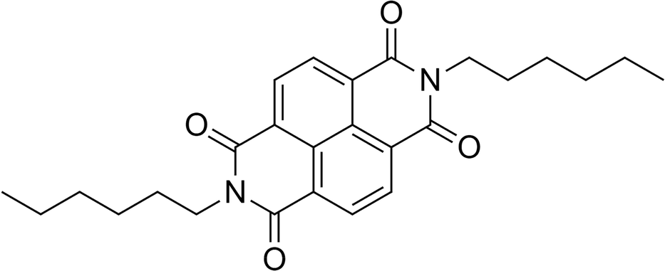 | ||
| Fig. 1 Chemical structure of NDI-C6. | ||
It is known that NDI-C6 is prone to generating several polymorphs, and the number of crystal forms is higher compared to the analogous molecules with shorter or higher chain length, nonetheless only the crystal structure of the most stable polymorph (Form α) is available.24 Up to now, four different polymorphs have been reported: Form α the stable form at RT, and Form β, Form γ and Form δ – which can be obtained by thermal treatement and all convert back to Form α at RT.27 Several papers report the preparation of thin films based on NDI-C6,4,26–29 but only recently have the thin films been characterized by X-ray diffraction and revealed the presence of a mixture of Form α and a metastable polymorph at room temperature.26,27 Herein, the main goal of this work is to study and understand the polymorphic behaviour of NDI-C6 in bulk and in thin films, with a special focus on the thermal behaviour. In fact, the annealing procedure is a common way to increase the performance of the devices, increasing the crystallinity,30,31 but in the case of NDI-C6 it can induce wanted or unwanted phase transitions. The synergic approach of the different thermal techniques such as hot stage optical microscopy (HSM), differential scanning calorimetry (DSC), and variable temperature X-ray powder diffraction (VT-XRPD), allowed us to determine the ranking in energy of the different polymorphs and to optimize different annealing procedures to obtain the desired phase in bulk and thin film. We were able to solve the structure of Form γ at high temperature by X-ray powder diffraction with synchrotron radiation. Furthermore, we optimized the thin film deposition to obtain pure phases and we discovered a new phase called ε.
Experimental
Materials
N,N′-Bis(n-hexyl)naphthalene-1,4,5,8-tetracarboxylic diimide (NDI-C6) is commercially available, it was purchased from Sigma-Aldrich and used as received.Polymorph screening
The NDI-C6 solubility was assessed in 12 different solvents at RT, 50 °C, 75 °C, and 100 °C when possible (see Table 1 in ESI†). Recrystallization by solvent evaporation was carried out in chloroform (CHF) and dichloromethane (DCM) at RT, in toluene (TOL) and p-xylene (PXY) at high temperature (60 °C) which presented the higher solubility.For the remaining solvents and solvent mixtures of toluene and methanol (MET), with different ratios, slurry experiments at RT were performed. High temperature slurries were carried out for N,N-dimethylformamide (DMF) at 90 °C, 2-propanol (2PR), acetonitrile (ACN), and water (H2O) at 50 °C. With the residual mother liquid obtained after filtration of the precipitate in the DMF solution, a high temperature (60 °C) evaporation experiment was set.
Crystallization by anti-solvent addition was performed testing TOL![[thin space (1/6-em)]](https://www.rsc.org/images/entities/char_2009.gif) :MET (1:1.25 vol), PXY:MET (1:1.20 vol), CHF:N-heptane (HEP) (1:2 vol), DCM:acetone (ACT) (1:1.33 vol), and CHF:MET (1:1.5 vol).
:MET (1:1.25 vol), PXY:MET (1:1.20 vol), CHF:N-heptane (HEP) (1:2 vol), DCM:acetone (ACT) (1:1.33 vol), and CHF:MET (1:1.5 vol).
Precipitation by gradient temperature was performed by crash cooling of DMF solutions and a solvent mixture of TOL:MET (1:1). Slow cooling crystallization was also tested with DMF solutions at different concentrations, using different cooling rates.
Solvothermal crystallization was carried out using TOL and PXY saturated solutions.
X-ray powder diffraction (XRPD)
All the precipitates obtained from the polymorph screening experiments, as well as the starting material, were characterized by XRPD to identify the crystalline phase. The XRD patterns were obtained using a Rigaku MiniFlex 600 diffractometer with Cu Kα (λ = 1.54178 Å) radiation from a copper sealed tube with 40 kV voltage and 15 mA current in Bragg–Brentano geometry, over the 2θ range of 3–40° with a step size of 1 0.01° (2θ) at a speed of 10.0° min−1 (2θ).Differential scanning calorimetry (DSC)
The starting material was characterized by differential scanning calorimetry (DSC) using a Mettler-Toledo DSC-1 instrument. The samples were prepared by accurately weighing approx. 2–4 mg of the powder in aluminium closed pans (40 μL). The measurements were performed during two cycles of heating and cooling with different rates (2 °C min−1, 5 °C min−1 and 10 °C min−1) under a dry N2 atmosphere (flow rate 80 mL min−1). All the data were analysed using STARe software.Hot stage microscopy (HSM)
The thermal behaviour of the material was studied by hot stage microscopy (HSM), the transitions were observed on a single crystal of Form α, grown by precipitation by gradient temperature with a slow cooling rate, using an OLYMPUS BX41 stereomicroscope equipped with a LINKAM LTS350 platinum plate for temperature control and VISICAM analyser. The single crystal is placed on a glass slide and covered with a coverslip; next, it is set inside of the sealed heating chamber.During the experiment time-lapse images were taken using a NIKON DS FI3 high speed camera and analysed using Nikon NIS Elements software and Linksys32.
Variable temperature X-ray powder diffraction (VT-XRPD)
VT-XRPD in transmission mode was performed at the Paul Scherrer Institute (PSI) synchrotron radiation facility (Switzerland) at MS-X04SA beamline using a well filled and compacted capillary with NDI-C6 powder. The MS powder diffractometer used works in Debye–Scherrer geometry and is equipped with a solid-state silicon microstrip detector, called MYTHEN (Microstrip sYstem for Time-rEsolved experimeNts).32 The data were collected with a beam energy of 12.4 keV (1.0 Å). The characterization was executed in a temperature range from 20 °C to 195 °C, to observe the several transitions that occur during temperature variation.VT-XRPD in reflection mode were performed on a PANalytical X’Pert Pro automated diffractometer with an X’Celerator detector in Bragg–Brentano geometry, using Cu Kα radiation (λ = 1.5418 Å) without a monochromator in the 2θ range of 3–30.0° under continuous scan mode, step size of 0.0167°, counting time of 24.765 s, Soller slit of 0.04 rad, 40 mA and 40 kV equipped with an Anton Paar TTK 450 system for measurements at a controlled temperature.
Thin films deposition
Various thin films were fabricated by spin-coating on 2 × 2 cm2 SiO2/Si substrates, previously cleaned by sonication in an ethanol bath, followed by sonication in an acetone bath and finally rinsed with deionised water and dried with compressed air. Deposition was carried out varying the process parameters: solvent, concentration, and speed. In addition, thermal annealing at 75 °C for 1 hour was performed for some samples. The details of the process parameters are summarised in Table 1.| Solvent | Concentration | Speed | Number of layers | Thermal annealing |
|---|---|---|---|---|
| TOL | 1 mg mL−1 | 1000 rpm | 1 | No |
| Yes | ||||
| 2 | No | |||
| 3 | No | |||
| 750 rpm | 1 | No | ||
| 3 mg mL−1 | 1000 rpm | 1 | No | |
| DCM | 1 mg mL−1 | 1000 rpm | 1 | No |
| 2 | No | |||
| 3 | No | |||
| 750 rpm | 1 | No | ||
| Yes | ||||
| 3 mg mL−1 | 1000 rpm | 1 | No | |
| CHF | 1 mg mL−1 | 750 rpm | 1 | No |
| Yes |
Structure determination from powder
Indexing, structure determination and refinement of Form γ was performed using TOPAS v5, a nonlinear least-squares optimization program written in the C++ programming language.33,34 The X-ray powder diffraction pattern of Form γ at 54 °C was indexed with triclinic cell with parameters: a = 4.855 Å, b = 6.471 Å, c = 19.946 Å, α = 92.14°, β = 95.83°, γ = 104.22 and volume 603 Å3 and space group P![[1 with combining macron]](https://www.rsc.org/images/entities/char_0031_0304.gif) . The simulated annealing was performed with a half molecule constrained on the inversion centre. The best solution was chosen for Rietveld refinements, which were performed with the software TOPAS. A shifted Chebyshev function with five parameters and a pseudo-Voigt function were used to fit background and peak shape, respectively. An overall thermal parameter was adopted for all atoms of non-hydrogen atoms. All the hydrogen atoms were fixed in calculated positions. The Rietveld refinement reached the following values: Rwp = 3.45%, R = 2.12%, GoF = 2.81.
. The simulated annealing was performed with a half molecule constrained on the inversion centre. The best solution was chosen for Rietveld refinements, which were performed with the software TOPAS. A shifted Chebyshev function with five parameters and a pseudo-Voigt function were used to fit background and peak shape, respectively. An overall thermal parameter was adopted for all atoms of non-hydrogen atoms. All the hydrogen atoms were fixed in calculated positions. The Rietveld refinement reached the following values: Rwp = 3.45%, R = 2.12%, GoF = 2.81.
PASCal
PASCal – Principal Axis Strain Calculator is a web-based tool used to determine the principal coefficients of thermal expansion from variable-temperature lattice parameters.35 The input data needed by the tool is simply the value of the temperature and the unit cell parameters at each temperature, for that we used the diffractograms acquired at PSI and refined the cell parameters using Pawley refinement. The tool returns as output the principal axis of thermal expansion and the orientation of the principal axes relative to the axes of the unit cell.Results and discussion
Polymorph screening
Recrystallization experiments in ACN, ACT, CHF, DCM, MET, TOL, H2O, 2PR, ETA and PXY led to the isolation of pure Form α, either as a powder or single crystals. The single crystals were obtained by temperature gradient precipitation with a slow cooling profile. Crash cooling experiments in DMF allowed the concomitant crystallization of Form α and Form β in powder mixture. Furthermore, a mixture of the two different forms was also attained by evaporating at 60 °C, the filtered mother liquor from high temperature slurry experiments in DMF.Recrystallization gave pure Form α or a mix with Form β. However, we were able to obtain pure Form β by annealing Form α. Phases γ and δ were observed only at high temperature, and it was not possible to achieve them at room temperature in bulk. However, in thin films it was possible to isolate Form α, Form β and Form γ at room temperature.
Thermal properties
We performed DSC, HSM and VT-XRPD on NDI-C6 to characterize its thermal behaviour and the results were compared to determine the different phases obtained during the thermal treatment.DSC analysis was based on the first heating, cooling and second heating cycles.
During the first heating of the starting material, the DSC curve presents a solid–solid transition around 178 °C before the melting point at 207 °C, Fig. 2b. This coincides with what has been described before by Milita et al.27 and is ascribable to a double transition: Form α → Form γ suddenly followed by the transition of Form γ → Form δ. The Form α → Form δ transition could be clearly observed by HSM at 180 °C (see Fig. S1 in ESI†).
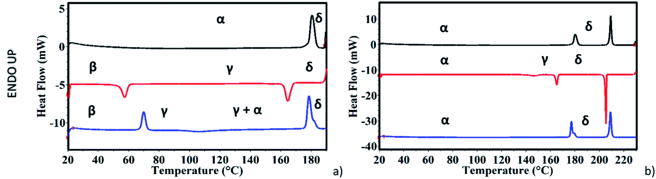 | ||
| Fig. 2 DSC curves of NDI-C6, (a) heating cycle before melting, black line: first heating, up to the first transition Form α, γ → Form δ, red line: first cooling with two exothermic events, Form δ → Form γ at 163 °C and Form γ → Form β at 56 °C, blue line: second heating, with an endothermic peak at 69 °C Form β → Form γ, at 110 °C an exothermic peak related to the partial conversion of Form γ into Form α, and at 177 °C an endothermic peak Form γ + α → Form δ. (b) Heating cycle up to melting, black line: first heating, at 178 °C transition Form α, γ → Form δ, at 206 °C melting, red line: first cooling with three exothermic events recrystallization into Form δ at 205 °C, Form δ → Form γ at 165 °C, and Form γ → Form α at 143 °C, blue line: second heating, at 178 °C transition Form α, γ → Form δ, at 206 °C melting. | ||
The VT-XRPD data (Fig. 3) are consistent with the described behaviour, an extra peak belonging to Form γ, appeared during the transition (around 180 °C), and disappeared concomitantly with the peaks of Form α once the transition into Form δ was complete.
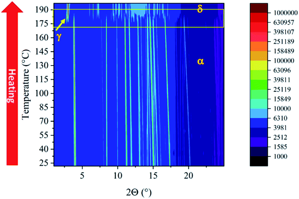 | ||
| Fig. 3 VT-XRPD of NDI-C6 at PSI synchrotron, 2D isolines of first heating until 195 °C with a transition of Form α → Form δ at 180 °C, and the presence of the Form γ peak is highlighted with an arrow. | ||
While the first heating cycle of the NDI-C6 Form α was always reproducible, the cooling cycle showed two different behaviours depending on whether the sample was melted or not. When the DSC experiment was performed without reaching the melting point of NDI-C6, the cooling curve matched with the behaviour already reported27 with the Form δ → Form γ transition at 163 °C and followed the Form γ → Form β transition at 56 °C, ending up with Form β as a metastable phase at room temperature (Fig. 2a).
On the other hand, by heating up the sample above the melting point, we observed a different pathway. By recrystallization at 205 °C, Form δ was obtained which converted into Form γ at 165 °C; the latter, unexpectedly converted into Form α at 143 °C (Fig. 2b). The presence of Form α at RT was confirmed by the second heating which was characterized by the almost concomitant double transition at around 175 °C ending in Form δ. Furthermore, we confirmed this behaviour by VT-XRPD: the NDI-C6 was melted and recrystallized on the sample stage. After melting, the sample is characterized by a strong preferential orientation, but the position of the first peak was used for the determination of the different phases and confirmed the presence of Form α at room temperature (see Fig. S3 in ESI†).
The thermal behaviour was studied by visual observation of the solid–solid transitions of NDI-C6 by HSM. A crystal was heated above the melting point (214 °C), and then cooled at −10 °C min−1 as shown in Fig. 4. The liquid crystallized as Form δ at 203 °C, as observed also in DSC analysis. Decreasing the temperature, we observed a transition at 160 °C, that corresponded to the transition from Form δ to Form γ, then, at 145 °C, the transition Form γ → Form α occurred. No other transition was detected during the cooling, ending up with only Form α in the sample.
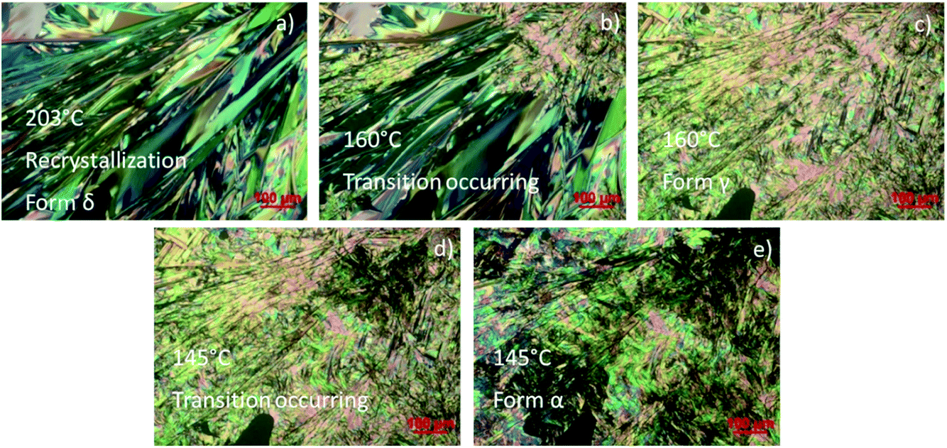 | ||
| Fig. 4 Hot stage microscopy during the cooling after the melting of a single crystal NDI-C6, (a) recrystallization at 203 °C into Form δ, (b) Form δ → Form γ transition starting at 160 °C, (c) transition into Form γ completed, (d) transition Form γ → Form α occurring at 145 °C, (e) transition into Form α completed. | ||
During the VT-XRPD collected at PSI, the sample was not melted and during the cooling, the transitions observed matched with the DSC analysis: Form δ converted into Form γ around 157 °C and then Form γ converted into Form β at 48 °C (see Fig. 2a and Fig. 5a). It is worth noting, that the remarkable thermal stability of Form γ was present in a temperature window of more than 100 °C and showed a high thermal contraction.
 | ||
| Fig. 5 VT-XRPD of NDI-C6 at PSI synchrotron, (a) 2D isolines during first cooling from 195 °C to RT, starting at Form δ and ending at Form β. Two transitions are observable Form δ → Form γ at 157 °C and Form γ → Form β at 48 °C. (b) 2D isolines view of the second heating from RT to 195 °C, with two transitions: Form β → Form γ at 73 °C and Form γ → Form δ at 187 °C, it is also visible by the presence of two peaks of Form α, highlighted in the figure with arrows, the peak at lower 2θ is already present before the transition Form β → Form γ but the intensity increases considerably around 110 °C. | ||
During the second heating, the DSC curve showed the conversion of Form β into Form γ at 69 °C then, an exothermic event occurred at 100 °C, which was ascribed to the partial formation of Form α as confirmed by the VT-XRPD, see Fig. 5b. This event suggests that Form α is more stable than Form γ at temperatures lower than 175 °C, and that the conversion Form γ → Form α is promoted by the high temperature. In the temperature range 175–180 °C the two transitions – Form α → Form γ, and Form γ → Form δ – occurred.
The VT-XRPD data confirmed the behaviour observed in DSC, pure Form β is obtained by cooling the sample annealed to 195 °C (Fig. 5b) upon heating it converts into Form γ at 73 °C. It is worth noting that at around 108 °C the peaks associated with the interplanar distances 14.28 Å and 6.75 Å of Form α appeared, which are related to the exothermic transition observed in the DSC. Form α and Form γ coexist up to 183 °C when Form α is fully converted into Form γ, then at 187 °C Form δ appears and the transition is completed at 190 °C.
The synergic approach of the different techniques allows us to rank the stability of the polymorphs: Form α is stable until 175 °C, then Form γ is stable until 178 °C when it converts into Form δ which is stable until the melting at 207 °C. Form β is always metastable but its energy should be between Form α and Form γ.
More difficult is rationalizing what causes the different thermal behaviour in cooling since they share common transitions: in fact, in both cases the high temperature Form δ converts into Form γ, only at this stage, the two pathways are observed. The different annealing process probably produces Form γ with different morphology or crystallinity which ends up in a different metastability of the crystals. When Form γ converts at high temperatures (145 °C) the thermal energy allows us to directly reach the stable Form α, instead, when the Form γ endures until 60 °C, it converts into Form β because the lower thermal energy is not enough to overcome the activation energy to reach Form α.
Thin films
We explored different combinations of solvent, deposition parameters and post-deposition treatment to obtain different films of different polymorphs. As expected, the crystal phases deposited are highly oriented and only the main peak is observed. The peak (100) of the Si at 33.00° (ref. 36) was used as the internal standard to determine the correct 2θ position of the peaks, and Table 2 summarizes the peak position used to identify the different phases.| Form | d (Å) | hkl | 2θ (°) |
|---|---|---|---|
| Form α | 14.3 | (001) | 6.2 |
| Form β | 18.3 | (001) | 4.9 |
| Form γ | 19.8 | (001) | 4.4 |
| Form δ | 19.0 | (002) | 4.6 |
| Form ε | 17.0 | — | 5.2 |
By spin coating deposition of a low concentrated solution of NDI-C6 in DCM, it was possible to obtain three different phases in the same film: Form α, Form β and a new form called Form ε, which was not observed before in the bulk analysis, Fig. 6. Form ε presents a strong peak at 5.2° that is not present in the other forms, and it clearly shows a new phase. Form ε was observed only in thin films crystallized on Si/SiO2 substrates: it is worth noting that since Form ε could be obtained also by quenching the melted NDI-C6 on Si/SiO2 substrates, this suggests that the new form might be induced by the substrate.
 | ||
| Fig. 6 Thin film prepared with a DCM solution showing a mixture of three different phases (Form α, Form β and Form ε). | ||
By changing concentration, speed or the number of layers, we always obtained a mixture of phases with Form α always present.
In films prepared using CHF solutions, only the Form α and Form ε were present as a mixture. It was possible to obtain pure Form α by thermal annealing at 75 °C, Fig. 7.
 | ||
| Fig. 7 Thin films of the different phases, identified by the characteristic peak of each phase, Form α in red, Form β in blue, Form γ in black and Form ε in green. | ||
By spin coating of toluene solutions with a speed of 1000 rpm, Form ε was obtained but it starts converting into Form β after a short time, Fig. 7.
A Form γ film is obtained by thermal treatment of Form β film at 75 °C (Fig. 7).
It is worth noting that the more polar and volatile solvents (DCM and CHF) favour the deposition of the stable Form α, although always concomitant with other metastable phases (Form β and Form ε) potentially promoted by the fast evaporation of the solvent. Toluene, on the other hand, favours the presence of ε, and despite being a high boiling solvent, the stable Form α is hardly observed. The main peaks observed in the thin films are ascribable to the alignment of the molecules on the substrate and it is worth noting that the β, γ and ε are characterized by peaks at lower angles than α, which indicates that NDI-C6 molecules are less tilted in respect to the substrate as observed for the γ phase. The longer planar distance is also induced by different conformation of the chains as discussed in the next section.
Crystal structure
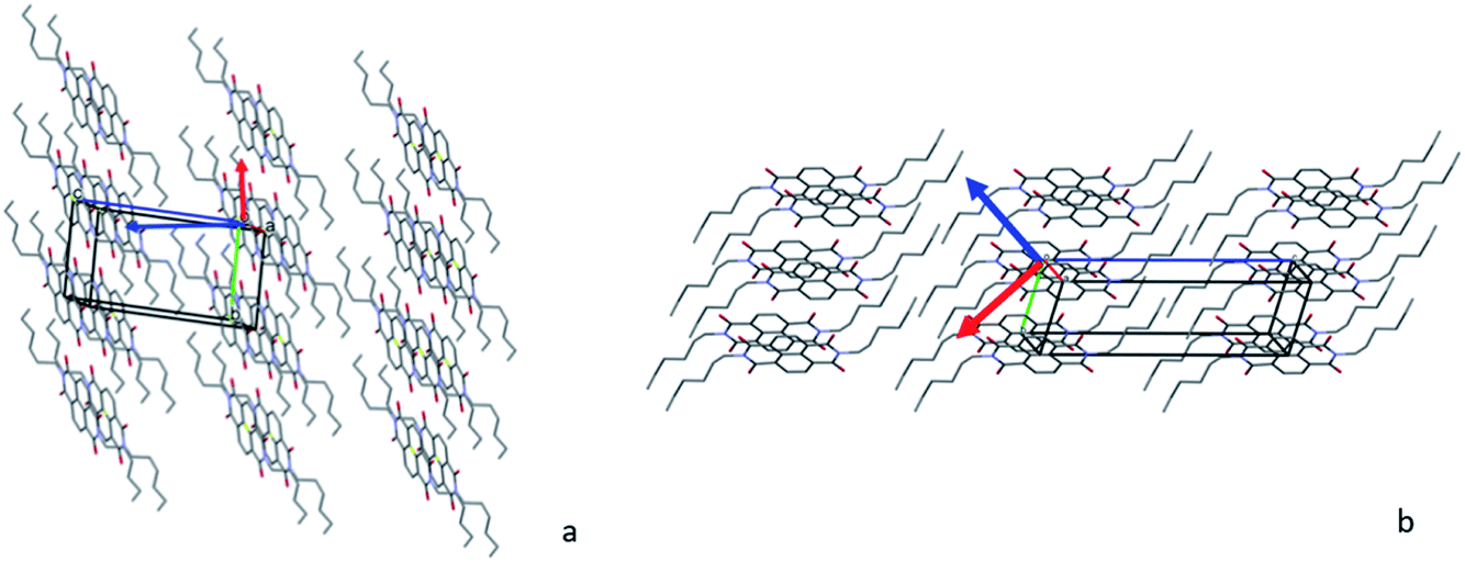
Structure solution of Form γ was obtained by simulated annealing with TOPAS 5. The X-ray powder pattern of Form γ at 54 °C was indexed with a triclinic cell with a volume comparable with the molecular volume, the simulated annealing was performed with a half molecule constrained on the inversion centre.As observed for the NDI-Cn molecules, the overall structures can be described as the stacking of layers of molecules, showing on the interface the alkyl chains. Conformation and length of the chains play a key role in the final structure tuning the aromatic core interactions. In Form γ, the alkyl chains of NDI-C6 present a quite different conformation in respect to Form α, although the carbon atoms do not adopt a full anti conformation, the chain is stretched, increasing the long axis of the molecule (see Fig. 8a and b). In both structures, the molecules form π–π interactions, with mainly columnar packing, the interplanar distance of Form γ is slightly longer than in Form α (3.5 Å instead of 3.4 Å), which allows the nearby columns to get tighter (see Fig. 8c and d). The different arrangement of the aromatic core can be better evaluated with the use of the stacking vector (SV) and the angles χ and ψ as described by Milita et al.27 The SVs are similar in both Form α and Form γ (4.90 Å and 4.86 Å respectively), but they have quite a different orientation, hence different χ and ψ values (76.0° and 46.4° in Form α and 64.7° and 58.4° in Form γ). The clustering of the different χ/ψ values for the NDI-Cn shows two different stacking modes, one for the short alkyl chains (n < 7) and the other for the longer ones. Interestingly the values obtained for Form γ are closer to the group of longer chains, where the energy contribution of the chains is predominant.
 | ||
| Fig. 8 Comparison of the structure of Form α (left) and Form γ (right): (a and b) different conformation of the chains in the NDI-C6 structures (hydrogen omitted for clarity); (c and d) columnar arrangement of the aromatic core, view along the long direction of the aromatic core; (e and f) columnar arrangement of the aromatic core, view perpendicular to the aromatic core. In c–f hydrogen atoms and alkyl chains are omitted for clarity. | ||
The thin films of Form α and Form γ are highly orientated and in both cases the highest peak is due to the crystallographic plane (001), which means that the planes (00l) are parallel to the substrate. Fig. 9 shows how the molecules of Form α and Form γ are organized on the substrate, and since in Form γ the NDI-C6 molecules are less tilted in respect to the substrate than in Form α, the d0 0 1 is longer and the first peak is observed at a lower 2θ angle than the peak of Form α.
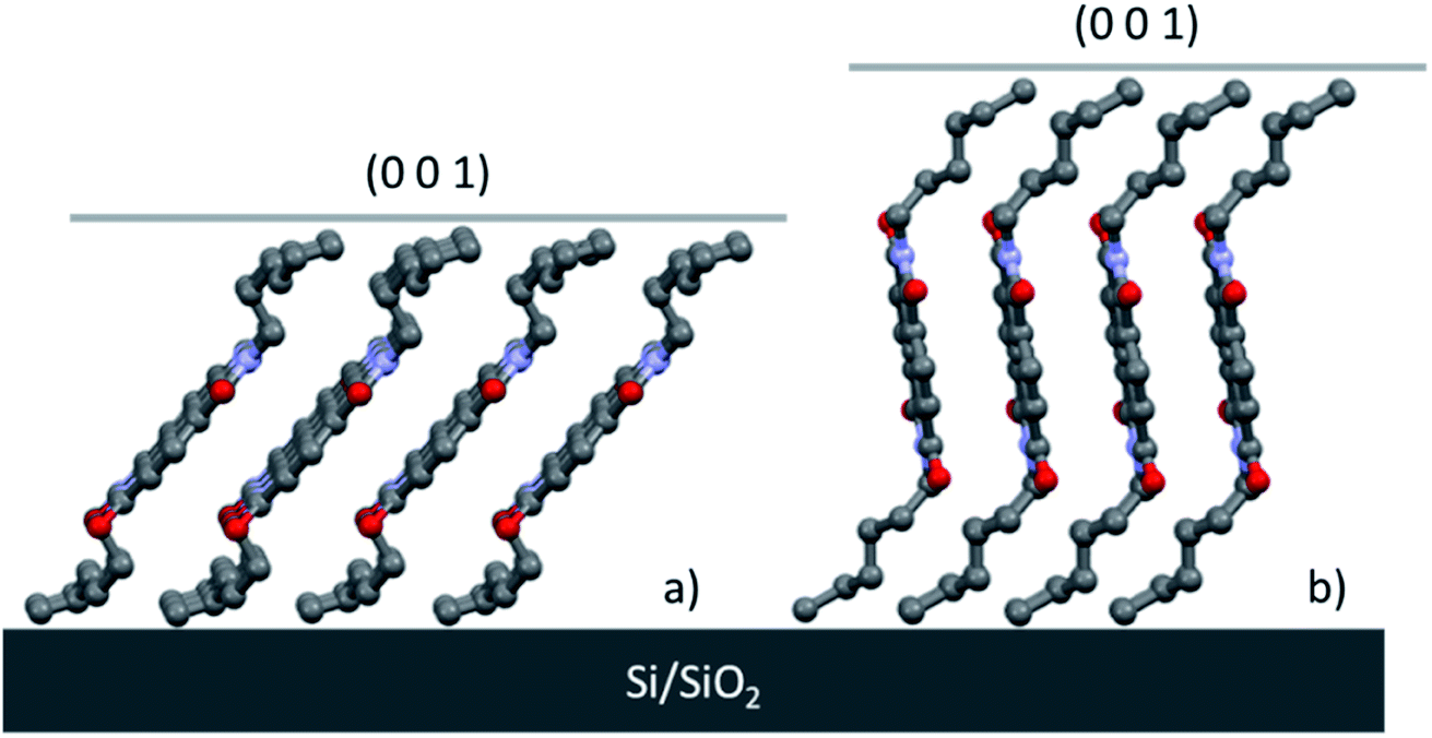 | ||
| Fig. 9 Molecular arrangement of thin films oriented in the Si/SiO2 substrates of (a) Form α and (b) Form γ. | ||
Thermal expansion calculation
As mentioned previously, NDI-C6 presents a big thermal expansion that could be noticed by the peak shift in the VT-XRPD. To have better insight into the thermal expansion mechanism, we used PASCal to analyse Form α and Form γ. The principal axis coefficients and the orientation of the tensors are summarized in Table 3.35 It is worth noting that the tensors are a set of orthogonal axes (the principal axes) along which the material responds in a purely linear fashion, and in the case of the triclinic system they are not related to the unit-cell axes.| Principal axis | αX (MK−1) | a | b | c | |
|---|---|---|---|---|---|
| Form α | X1 | −87 | −0.3966 | −0.9180 | 0.0040 |
| X2 | 133 | 0.9847 | −0.0715 | 0.1590 | |
| X3 | 308 | −0.6626 | 0.2685 | 0.6992 | |
| Form γ | X1 | −292 | 0.1631 | 0.9478 | −0.2740 |
| X2 | 193 | 0.9613 | −0.2584 | −0.0957 | |
| X3 | 552 | −0.7771 | −0.5966 | −0.2005 |
Looking at the results obtained, we can immediately see that both polymorphs have a negative thermal expansion (NTE) along one principal axis, this behaviour is uncommon but it has been described in different materials before, for example in BHH-BTBT.37,38
In Form α, the highest positive thermal expansion positive thermal expansion (PTE) of 308 MK−1 can be considered a huge expansion39 and it affects the distances between the layers (see Fig. 10a), which involves mainly the alkyl chains, while the NTE occurs inside the layer and affects mainly the distances between the side-by-side aromatic core, these two effects promote the conversion into Form γ, where the alkyl chains are more stretched, and the columns are closer. As observed before, increasing the temperature allows to reach this new family of phases where the arrangement of the aromatic core is closer to the one observed for the NDIs with long chains and the molecules are less tilted with respect to the (0 0 1) plane, which can be detected by the first peak as low 2θ values.
 | ||
| Fig. 10 Packing of the structures with X2 perpendicular to the figure, X1 in red and X3 in blue. The arrows indicate the direction of the tensors: (a) Form α and (b) Form γ. | ||
It is worth noting that in Form γ the thermal expansion is highly anisotropic, with a colossal NTE (X1 = −292 MK−1) and a massive PTE (X3 = 552 MK−1) using the notation proposed by Goodwin et al.39 and Henke et al.40 In Fig. 10b the X1 and X3 are reported, and considering that the component of X1, X2 and X3 along the c axis are limited, it suggests that the main rearrangement occurs in the intralayer and the tilt of the molecules. This behaviour can explain the different thermal pathways, when the transition Form γ → Form α occurs at high temperature, it is possible to rearrange the chains and reach the stable Form α. On the other hand, if Form γ reaches a low temperature, the contraction that occurs during the cooling, which involves mainly the layer, compresses the alkyl chains preventing their folding, and instead of Form α, Form β is obtained, which is characterized by a longer axis.
Conclusion
We have studied in detail the thermal behaviour of NDI-C6, already known for the high number of polymorphs that can be detected by varying temperature. The careful study of the transition allowed us to determine the stability of the different polymorphs: Form α is stable up to 175 °C, then Form γ is stable until 178 °C when it converts into Form δ which is stable until it melts at 207 °C. Form β is always metastable and its energy is supposed to be between Form α and Form γ. This study revealed that depending on the thermal history, it is possible to achieve different phases at RT: Form α or Form β. The former is obtained by cooling of the melt while the latter is obtained by annealing until below the melting point (206 °C), this phase is metastable at RT, and it reconverts into Form α over time. We were able to determine the crystal structure of Form γ, where the NDI-C6 presents almost stretched alkyl chains, and an overall packing closer to the structure of NDI-Cn with n > 7. Form α and Form γ present exceptionally high PTE and NTE values, and the analysis of the principal coefficients of thermal expansion gave us insight into the solid–solid transition. In Form α, the highest PTE influences mainly the interlayer distance and upon heating, promotes the stretching of the alkyl chains and thus the conversions to Form γ. On the other hand, colossal NTE and massive PTE calculated on Form γ, are predominant in the ab plane, hence in the arrangement of the aromatic cores. Upon cooling, if the transition to Form α does not occur at high temperature, Form γ reaches low temperatures, and the contraction that occurs during the cooling prevents the folding of the alkyl chains and instead of Form α, Form β is obtained, which is characterized by a longer axis.By different combinations of solvent, speed of deposition and thermal annealing, it was possible to obtain pure phases on the thin film. DCM and CHF promoted the formation of a mixture of Form α with different phases, while, by deposition of toluene solutions, a new polymorph labelled Form ε was observed. The new form is metastable and converts into Form β over time. Pure Form α and γ were obtained by thermal annealing at 75 °C for 1 h of the sample obtained with DCM and TOL solution, respectively. Form ε has been observed only on Si/SiO2 substrates and further investigations are planned to confirm that it is a substrate-induced polymorph.
Author contributions
Inês de Oliveira Martins: investigation, experimental and computational analysis and writing of the manuscript. Francesco Marin: experimental and computational analysis. Enrico Modena: conceptualization and supervision. Lucia Maini: supervision, manuscript review and editing.Conflicts of interest
The authors declare no conflicts of interestAcknowledgements
We acknowledge the Paul Scherrer Institut, Villigen, Switzerland for provision of synchrotron radiation beamtime at beam-line MS-X04SA of the SLS (ID proposal 20201790) and would like to thank Nicola P. M. Casati for assistance. This project has received funding from the European Union’s Horizon 2020 research and innovation programme under the Marie Skłodowska-Curie grant agreement no. 811284 (UHMob).References
- Y. Diao, L. Shaw, Z. Bao and S. C. B. Mannsfeld, Morphology Control Strategies for Solution-Processed Organic Semiconductor Thin Films, Energy Environ. Sci., 2014, 7, 2145–2159, 10.1039/c4ee00688g.
- J. Mei, Y. Diao, A. L. Appleton, L. Fang and Z. Bao, Integrated Materials Design of Organic Semiconductors for Field-Effect Transistors, J. Am. Chem. Soc., 2013, 135(18), 6724–6746, DOI:10.1021/ja400881n.
- X. Gao and Z. Zhao, High Mobility Organic Semiconductors for Field-Effect Transistors, Sci. China: Chem., 2015, 58(6), 947–968, DOI:10.1007/s11426-015-5399-5.
- C. Zhao, A. Li, X. Chen, M. U. Ali and H. Meng, Hysteresis Effect in Organic Thin Film Transistors Based on Naphthalene Tetracarboxylic Diimide Derivatives, Appl. Phys. Lett., 2021, 118, 193302, DOI:10.1063/5.0045183.
- K. Fukuda, Y. Takeda, M. Mizukami, D. Kumaki and S. Tokito, Fully Solution-Processed Flexible Organic Thin Film Transistor Arrays with High Mobility and Exceptional Uniformity, Sci. Rep., 2014, 4, 3947, DOI:10.1038/srep03947.
- S. Riera-Galindo, A. Tamayo and M. Mas-Torrent, Role of Polymorphism and Thin-Film Morphology in Organic Semiconductors Processed by Solution Shearing, ACS Omega, 2018, 3, 2329–2339, DOI:10.1021/acsomega.8b00043.
- H. Chung and Y. Diao, Polymorphism as an Emerging Design Strategy for High Performance Organic Electronics, J. Mater. Chem. C, 2016, 4(18), 3915–3933, 10.1039/c5tc04390e.
- X. Gao and Y. Hu, Development of N-Type Organic Semiconductors for Thin Film Transistors : A Viewpoint of Molecular Design, J. Mater. Chem. C, 2014, 17, 3099–3117, 10.1039/c3tc32046d.
- E. Benvenuti, D. Gentili, F. Chiarella, A. Portone, M. Barra, M. Cecchini, C. Cappuccino, M. Zambianchi, S. G. Lopez, T. Salzillo, E. Venuti, A. Cassinese, D. Pisignano, L. Persano, M. Cavallini, L. Maini, M. Melucci, M. Muccini and S. Toffanin, Tuning Polymorphism in 2,3-Thienoimide Capped Oligothiophene Based Field-Effect Transistors by Implementing Vacuum and Solution Deposition Methods, J. Mater. Chem. C, 2018, 6(21), 5601–5608, 10.1039/c8tc00544c.
- C. Cappuccino, S. Canola, G. Montanari, S. G. Lopez, S. Toffanin, M. Melucci, F. Negri and L. Maini, One Molecule, Four Colors: Discovering the Polymorphs of a Thieno(Bis)Imide Oligomer, Cryst. Growth Des., 2019, 19, 2594–2603, DOI:10.1021/acs.cgd.8b01712.
- C. Cappuccino, L. Catalano, F. Marin, G. Dushaq, G. Raj, M. Rasras, R. Rezgui, M. Zambianchi, M. Melucci, P. Naumov and L. Maini, Structure–Mechanical Relationships in Polymorphs of an Organic Semiconductor (C4-NT3N), Cryst. Growth Des., 2020, 20, 884–891, DOI:10.1021/acs.cgd.9b01281.
- M. Mas-Torrent and C. Rovira, Role of Molecular Order and Solid-State Structure in Organic Field-Effect Transistors, Chem. Rev., 2011, 111(8), 4833–4856, DOI:10.1021/cr100142w.
- Y. Zhen, H. Dong, L. Jiang and W. Hu, Tailoring Crystal Polymorphs of Organic Semiconductors towards High-Performance Field-Effect Transistors, Chin. Chem. Lett., 2016, 27(8), 1330–1338, DOI:10.1016/j.cclet.2016.06.023.
- D. Liu, X. Xiao, Z. He, J. Tan, L. Wang, B. Shan and Q. Miao, Control of Polymorphism in Solution-Processed Organic Thin Film Transistors by Self-Assembled Monolayers, Sci. China: Chem., 2020, 63(9), 1221–1229, DOI:10.1007/s11426-020-9793-2.
- T. Salzillo, A. Campos, A. Babuji, R. Santiago, S. T. Bromley, C. Ocal, E. Barrena, R. Jouclas, C. Ruzie, G. Schweicher, Y. H. Geerts and M. Mas-torrent, Enhancing Long-Term Device Stability Using Thin Film Blends of Small Molecule Semiconductors and Insulating Polymers to Trap Surface-Induced Polymorphs, Adv. Funct. Mater., 2020, 2006115, DOI:10.1002/adfm.202006115.
- A. O. F. Jones, B. Chattopadhyay, Y. H. Geerts and R. Resel, Substrate-Induced and Thin-Film Phases : Polymorphism of Organic Materials on Surfaces, Adv. Funct. Mater., 2016, 26, 2233–2255, DOI:10.1002/adfm.201503169.
- L. Pithan, D. Nabok, C. Cocchi, P. Beyer, G. Duva, J. Simbrunner, C. Nicklin, P. Schäfer, C. Draxl, F. Schreiber, S. Kowarik, L. Pithan, D. Nabok, C. Cocchi, P. Beyer, G. Duva, F. Schreiber and S. Kowarik, Molecular Structure of the Substrate-Induced Thin-Film Phase of Tetracene, J. Chem. Phys., 2018, 149, 144701, DOI:10.1063/1.5043379.
- D. Reischl, C. Ro, P. Christian, E. Roblegg, H. M. A. Ehmann, I. Salzmann and O. Werzer, Surface-Induced Polymorphism as a Tool for Enhanced Dissolution: The Example of Phenytoin, Cryst. Growth Des., 2015, 15, 4687–4693, DOI:10.1021/acs.cgd.5b01002.
- A. O. F. Jones, Y. H. Geerts, J. Karpinska, A. R. Kennedy, R. Resel, C. Röthel, C. Ruzié, O. Werzer and M. Sferrazza, Substrate-Induced Phase of a [1]Benzothieno[3,2-b]Benzothiophene Derivative and Phase Evolution by Aging and Solvent Vapor Annealing, ACS Appl. Mater. Interfaces, 2015, 7, 1868–1873, DOI:10.1021/am5075908.
- O. D. Jurchescu, Conductivity Measurements of Organic Materials Using Field-Effect Transistors (FETs) and Space-Charge-Limited Current (SCLC) Technique, in Handbook of Organic Materials for Optical and (Opto)electronic Devices, Woodhead Publishing Limited, 2013, pp. 377–383, DOI:10.1533/9780857098764.2.377.
- S. V. Bhosale, M. Al Kobaisi, R. W. Jadhav, P. P. Morajkar, L. A. Jones and S. George, Naphthalene Diimides : Perspectives and Promise, Chem. Soc. Rev., 2021, 50, 9845–9998, 10.1039/d0cs00239a.
- Z. Ma, H. Geng, D. Wang and Z. Shuai, Influence of Alkyl Side-Chain Length on the Carrier Mobility in Organic Semiconductors : Herringbone vs. Pi–Pi Stacking, J. Mater. Chem. C, 2016, 4(20), 22–24, 10.1039/c6tc00755d.
- X. Guo, F. S. Kim, M. J. Seger, S. A. Jenekhe and M. D. Watson, Naphthalene Diimide-Based Polymer Semiconductors: Synthesis, Structure–Property Correlations, and n-Channel and Ambipolar Field-Effect Transistors, Chem. Mater., 2012, 24, 1434–1442, DOI:10.1021/cm2034273.
- D. Shukla, S. F. Nelson, D. C. Freeman, M. Rajeswaran, W. G. Ahearn, D. M. Meyer and J. T. Carey, Thin-Film Morphology Control in Naphthalene-Diimide-Based Semiconductors : High Mobility n-Type Semiconductor for Organic Thin-Film Transistors, Chem. Mater., 2008, 20(24), 7486–7491 CrossRef CAS.
- X. Chen, Y. He, M. U. Ali, Y. He, Y. Zhu, A. Li, C. Zhao, I. F. Perepichka and H. Meng, Isothianaphthene Diimide : An Air-Stable n-Type Semiconductor, Sci. China: Chem., 2019, 62, 1360–1364 CrossRef CAS.
- A. Welford, S. Maniam, E. Gann, X. Jiao, L. Thomsen, S. J. Langford and C. R. Mcneill, Influence of Alkyl Side-Chain Type and Length on the Thin Film Microstructure and OFET Performance of Naphthalene Diimide-Based Organic Semiconductors, Org. Electron., 2019, 75, 105378, DOI:10.1016/j.orgel.2019.105378.
- S. Milita, F. Liscio, L. Cowen, M. Cavallini, B. A. Drain, T. Degoussée, S. Luong, O. Fenwick, A. Guagliardi, B. C. Schroeder and N. Masciocchi, Polymorphism in N,N’-Dialkyl-Naphthalene Diimides, J. Mater. Chem. C, 2020, 8, 3097–3112, 10.1039/c9tc06967d.
- D. Shukla, S. F. Nelson, D. C. Freeman, M. Rajeswaran, W. G. Ahearn, D. M. Meyer and J. T. Carey, Thin-Film Morphology Control in Naphthalene-Diimide-Based Semiconductors : High Mobility n-Type Semiconductor for Organic Thin-Film Transistors, Chem. Mater., 2008, 20(4), 7486–7491 CrossRef CAS.
- S. Ali, M. A. Jameel, A. Gupta, S. J. Langford and M. Shafiei, Capacitive Humidity Sensing Performance of Naphthalene Diimide Derivatives at Ambient Temperature, Synth. Met., 2021, 275, 116739, DOI:10.1016/j.synthmet.2021.116739.
- S. Cho, K. Lee, J. Yuen, G. Wang, D. Moses, A. J. Heeger, M. Surin and R. Lazzaroni, Thermal Annealing-Induced Enhancement of the Field-Effect Mobility of Regioregular Poly(3-Hexylthiophene) Films, J. Appl. Phys., 2006, 114503, DOI:10.1063/1.2400796.
- Y. Yuan, G. Giri, A. L. Ayzner, A. P. Zoombelt, S. C. B. Mannsfeld, J. Chen, D. Nordlund, M. F. Toney, J. Huang and Z. Bao, Ultra-High Mobility Transparent Organic Thin Film Transistors Grown by an off-Centre Spin-Coating Method, Nat. Commun., 2014, 5, 3005, DOI:10.1038/ncomms4005.
- P. R. Willmott, D. Meister, S. J. Leake, M. Lange, A. Bergamaschi, M. Böge, M. Calvi, C. Cancellieri, N. Casati, A. Cervellino, Q. Chen, C. David, U. Flechsig, F. Gozzo, B. Henrich, S. Jäggi-Spielmann, B. Jakob, I. Kalichava, P. Karvinen, J. Krempasky, A. Lüdeke, R. Lüscher, S. Maag, C. Quitmann, M. L. Reinle-Schmitt, T. Schmidt, B. Schmitt, A. Streun, I. Vartiainen, M. Vitins, X. Wang and R. Wullschleger, The Materials Science Beamline Upgrade at the Swiss Light Source, J. Synchrotron Radiat., 2013, 20(5), 667–682, DOI:10.1107/S0909049513018475.
- A. A. Coelho, TOPAS and TOPAS-Academic: An Optimization Program Integrating Computer Algebra and Crystallographic Objects Written in C++: An, J. Appl. Crystallogr., 2018, 51(1), 210–218, DOI:10.1107/S1600576718000183.
- J. S. O. Evans, Advanced Input Files & Parametric Quantitative Analysis Using Topas, Mater. Sci. Forum, 2010, 651, 1–9, DOI:10.4028/www.scientific.net/MSF.651.1.
- M. J. Cliffe and A. L. Goodwin, PASCal: A Principal Axis Strain Calculator for Thermal Expansion and Compressibility Determination, J. Appl. Crystallogr., 2012, 45(6), 1321–1329, DOI:10.1107/S0021889812043026.
- P. Zaumseil, High-Resolution Characterization of the Forbidden Si 200 and Si 222 Reflections, J. Appl. Crystallogr., 2015, 48, 528–532, DOI:10.1107/S1600576715004732.
- A. van Der Lee, G. H. Roche, G. Wantz, J. J. E. Moreau, O. J. Dautel and J. S. Filhol, Experimental and Theoretical Evidence of a Supercritical-like Transition in an Organic Semiconductor Presenting Colossal Uniaxial Negative Thermal Expansion, Chem. Sci., 2018, 9(16), 3948–3956, 10.1039/c8sc00159f.
- Z. Liu, Q. Gao, J. Chen, J. Deng, K. Lin and X. Xing, Negative Thermal Expansion in Molecular Materials, Chem. Commun., 2018, 54, 5164–5176, 10.1039/c8cc01153b.
- A. L. Goodwin, M. Calleja, M. J. Conterio, M. T. Dove, J. S. O. Evans, D. A. Keen, L. Peters and M. G. Tucker, Colossal Positive and Negative Thermal Expansion in the Framework Material Ag3[Co(CN)6], Science, 2008, 319(5864), 794–797, DOI:10.1126/science.1151442.
- S. Henke, A. Schneemann and R. A. Fischer, Massive Anisotropic Thermal Expansion and Thermo-Responsive Breathing in Metal–Organic Frameworks Modulated by Linker Functionalization, Adv. Funct. Mater., 2013, 23(48), 5990–5996, DOI:10.1002/adfm.201301256.
Footnote |
| † Electronic supplementary information (ESI) available. CCDC 2124322. For ESI and crystallographic data in CIF or other electronic format see DOI: 10.1039/d1fd00100k |
| This journal is © The Royal Society of Chemistry 2022 |