
 Open Access Article
 This Open Access Article is licensed under a
 Creative Commons Attribution 3.0 Unported Licence
Synthesis of methane hydrate at ambient temperature with ultra-rapid formation and high gas storage capacity†
Ye
Zhang‡
 a,
Jie
Zhao‡
abc,
Gaurav
Bhattacharjee
*a,
Huanzhi
Xu
a,
Mingjun
Yang
*c,
Rajnish
Kumar
*d and
Praveen
Linga
*a
a,
Jie
Zhao‡
abc,
Gaurav
Bhattacharjee
*a,
Huanzhi
Xu
a,
Mingjun
Yang
*c,
Rajnish
Kumar
*d and
Praveen
Linga
*a
aDepartment of Chemical and Biomolecular Engineering, National University of Singapore, Singapore 117585, Singapore. E-mail: chegaur@nus.edu.sg; chepl@nus.edu.sg
bCollege of Metrology and Measurement Engineering, China Jiliang University, Hangzhou 310018, China
cKey Laboratory of Ocean Energy Utilization and Energy Conservation of Ministry of Education, Dalian University of Technology, Dalian 116024, China. E-mail: yangmj@dlut.edu.cn
dDepartment of Chemical Engineering, Indian Institute of Technology Madras, Chennai, India. E-mail: rajnish@iitm.ac.in
First published on 21st November 2022
Abstract
With the emergence of natural gas (NG) as a crucial transition fuel, NG storage techniques have also become essential components of nations’ energy resilience portfolios. The Solidified Natural Gas (SNG) technology is one emerging technique that promises safe, long-term NG storage under moderate pressure and temperature (P–T) conditions. Herein we investigate 1,3-dioxane (dioxane), a low-toxicity chemical additive, as a potential dual-function (thermodynamic and kinetic) promoter for the SNG technology. By enabling mixed methane (sII) hydrate formation, dioxane significantly moderates the P–T conditions required for SNG synthesis. At 283.2 K temperature and 7.2 MPa initial pressure, mixed CH4/dioxane (5.56 mol%) sII hydrate growth under unstirred conditions reaches 90% completion within 15 min. At ambient temperature (298.2 K) and an initial pressure of 16.7 MPa, a breakthrough volumetric methane storage capacity of 135.13 (±1.08) v/v (volume of gas at STP/volume of hydrate) is achieved, wherein methane molecules occupy about 34% of the sII-large (51264) cages in addition to all of the sII-small (512) cages demonstrating tunability of methane in the large cages. Finally, a mixed CH4/dioxane hydrate pellet, stored in a tightly sealed container under near atmospheric pressure of 135.2 kPa (gauge pressure) and a moderate average temperature of 268.3 (±0.2) K for 120 days, exhibits excellent stability throughout the duration of storage. The present study demonstrates that the gas storage capacity of methane in sII hydrate can be tuned to exceed the acknowledged limit of about 115.36 v/v and that sII hydrates can be readily and rapidly synthesized at room temperature, aiding the development of an environmentally and commercially viable SNG technology.
Broader contextGas hydrate based Solidified Natural Gas (SNG) technology enables non-explosive, energy-dense natural gas (NG) storage with straightforward gas recovery. Reducing the energy requirement for hydrate formation, increasing methane storage capacity, and achieving long-term hydrate stability are crucial determinants in achieving commercialization of the SNG technology. Herein, we investigated 1,3-dioxane (dioxane) as a low-toxicity, low-volatility dual-function (thermodynamic and kinetic) promoter for the SNG technology. Ultra-rapid gas uptake rates and breakthrough (higher than acknowledged limit) methane storage capacity were achieved for mixed CH4/dioxane (5.56 mol%) sII hydrate formation at room temperature. Further, the sustained stability of a mixed CH4/dioxane hydrate pellet stored in a tightly sealed container under near atmospheric pressure and moderate temperature (268.3 (±0.2) K) was demonstrated. This landmark study represents an immense potential to develop a large-scale, long-term NG storage technology based on the mixed CH4/dioxane hydrate system. |
1. Introduction
Natural gas (NG) with methane gas as the major component, is unequivocally the cleanest-burning fossil fuel, and can partner with renewable energy sources to lend energy resilience to developed and developing economies alike.1–6 As endeavours to facilitate a sustainable energy transition are just now taking centre stage, the opportunity does remain for NG to enter an unprecedented golden age.7,8 In any scenario, fostering safe and robust technologies for natural gas storage is vital for addressing intermittencies in energy supply and solidifying nations’ energy resilience frameworks.9,10 The commercial NG storage technologies available currently are compressed natural gas (CNG) and liquefied natural gas (LNG). However, neither of these caters to simultaneous long-term and large-scale storage of NG because of either the higher pressure (20–25 MPa) requirements and safety issues (explosiveness) accompanying CNG,11 or the extremely low storage temperature (−162 °C) and boil-off issues associated with LNG.12 Solidified natural gas (SNG) enabling the storage of NG in solid hydrate form however, demonstrates great potential for commercially viable non-explosive storage of NG at a large scale, and at moderate pressure and temperature conditions.13–15Clathrate hydrates (or gas hydrates) are non-stoichiometric crystalline compounds consisting of host cages formed by water molecules through hydrogen bonding, and guest molecules such as methane,16–20 hydrogen,21–30 tetrahydrofuran,23,25,27etc., residing in the host cages.14,15,31,32 The solidified natural gas (SNG) technology via clathrate hydrates has several advantages such as ‘being operationally benign (the major raw material used is the green solvent water (>94% in solution))’; ‘offering high volumetric energy density – maximum methane storage capacity of about 172 (v/v; volumes of gas (at STP)/volume of hydrate) for sI pure methane hydrate, and about 115.36 v/v for sII mixed methane hydrate formed in the presence thermodynamic or dual-function promoters, assuming promoter occupancy in all the sII-51264 cages’; ‘allowing non-explosive storage of methane gas for long periods of time at moderate pressure and temperature conditions’ and finally, ‘promising straightforward recovery of the stored methane gas’.13
The SNG technology, generally comprising four steps (hydrate formation, dewatering, pelletizing, and hydrate storage),13,33 does pose its own challenges. Hydrate formation is an inherently gradual process which necessitates energy-intensive agitation to the system so as to ensuring rapid hydrate formation as well as sufficient gas uptake. The low temperature and high pressure conditions generally associated with gas hydrate formation further hamper the ease of operation. The thermodynamic stability conditions of pure methane hydrate also dictate that for stable hydrate storage at atmospheric pressure, a temperature as low as 253 K is required, where the anomalous ‘self-preservation’ effect would come into play.34–36 Further, the dewatering step to be negated requires converting a sufficient amount of water or aqueous solution into solid hydrate, whereas the pelletizing step necessitates the utilization of specific engineering unit operations, such as extrusion or a screw conveyor mechanism.13 Finally, the maximum volumetric methane storage capacity that may be achieved via the SNG technology is considerably lower than that may be attained via a conventional natural gas storage technology such as LNG.13
The SNG technology using tetrahydrofuran (THF) as a promoter has seen great progress over the latter half of the last decade, especially with regards to achieving rapid gas hydrate formation and stable storage of the mixed CH4/THF hydrate under moderate temperature and pressure conditions.33,37–40 However, the practical utilization of THF in an industrially viable SNG technology is hampered by the carcinogenicity, volatility, and corrosivity of the chemical.41 Thus, identifying alternatives to THF that could contribute to a more environment friendly SNG technology has become of paramount importance, with additives like 1,3-dioxolane (DIOX) that have lower volatility and lesser toxicity compared to THF already being explored.29,42–45 Ultra-rapid formation of mixed CH4/DIOX (sII) hydrate was achieved by Bhattacharjee and co-authors, under the experimental conditions of 283.15 K temperature and 7.2 MPa pressure, employing a hybrid combinatorial reactor (HCR) approach which still requires a small amount of agitation to be provided to the system so as to quickly trigger hydrate nucleation.42 DIOX and THF are unique in that they provide both thermodynamic and kinetic enhancement to the SNG technology process, i.e., they play a dual-function role as hydrate promoters.33,42,45 The emergence and utilization of such promoters has greatly enhanced the operational feasibility of the SNG technology.
In the present work, we aim to address the major challenges of the SNG technology mentioned above using the additive 1,3-dioxane (dioxane), a water-soluble, non-carcinogenic, and low volatility organic molecule that has seldom been explored in the hydrate community – the molecular structure and some relevant physico-chemical properties of this additive have been presented in Fig. 1a. To the best of our knowledge, the solitary work investigating the impact of dioxane on the thermodynamics of the methane hydrate system was published by Li et al. in 2019, with the authors simply reporting the dioxane molecule to be a thermodynamic promoter for methane hydrate formation.46 Herein, a deep-dive has been performed into a potential SNG technology (methane hydrate formation and storage process) promoted by the presence of dioxane in the aqueous hydrate forming solution. The closeness of dioxane's molecular structure to those of THF and DIOX (see Fig. 1a), well known dual-function promoters for the SNG technology, presents an exciting possibility of dioxane exhibiting similar promoting characteristics. Phase equilibrium data was first obtained for the mixed CH4/dioxane (5.56 mol%) hydrate system using the highly robust and efficient dissociation along the phase boundary (PB) method.44 Mixed CH4/dioxane hydrate formation was conducted under unstirred tank reactor (UTR) configuration (temperature of 283.2 K) or employing a hybrid combinatorial reactor (HCR) approach (temperatures above 283.2 K), as required, and the hydrophobic amino acid L-tryptophan was used as a kinetic promoter in small concentrations (ppm levels) to realize ultra-rapid hydrate growth. At the microscopic level, powder X-ray diffraction (p-XRD) characterization and in situ Raman spectroscopic analysis were conducted for the mixed CH4/dioxane hydrate system. Finally, the stability of a synthesized mixed CH4/dioxane hydrate pellet was tested by storing it in a tightly sealed container under near atmospheric pressure and a moderate target storage temperature of 268.2 K for a period of 120 days. Complete experimental details are provided in the methods section within the ESI.†
 | ||
| Fig. 1 (a) The molecular structures and critical physico-chemical properties of three organic hydrate guest molecules (i.e. dioxane, DIOX, and THF), relevant to their use as chemical promoters for the SNG technology; (b) the three phase (gas, liquid, hydrate) equilibrium conditions for four different methane-containing hydrate systems, namely, pure CH4 hydrate,44 mixed CH4/dioxane hydrate, mixed CH4/DIOX hydrate,44 and mixed CH4/THF hydrate;47 (c) Clausius–Clapeyron plots for the four different methane-containing hydrate systems obtained using the relevant three phase (liquid, gas, and hydrate) equilibrium data. | ||
2. Results and discussion
2.1. Measurement of three-phase equilibrium data for mixed CH4/dioxane hydrate
Fig. 1a presents the molecular structures and critical physico-chemical properties of three organic hydrate guest molecules (dioxane, DIOX, and THF), relevant to their use as chemical promoters for the SNG technology. THF's effectiveness as a thermodynamic promoter for methane hydrate formation has resulted in this molecule being investigated extensively for the SNG technology over the past decade.13,33,38,40 However, the severe volatility and toxicity of THF (Fig. 1a(iii)) have remained major bottlenecks towards its practical utilization in a large scale SNG technology, with researchers are now resorting to identifying potential alternatives to THF that exhibit similar thermodynamic promotion performance but are much safer to use. In a recently published work, our group reported ultra-rapid methane uptake using a seldom studied thermodynamic promoter 1,3-dioxolane (DIOX) (Fig. 1a(ii)) that has a lesser toxicity and lower volatility compared to THF. The results positioned DIOX as not just a thermodynamic promoter for methane hydrate formation but a dual-function one, i.e., an additive capable of imparting both thermodynamic and kinetic promotion to the SNG technology process.42 dioxane employed in the current study is non-carcinogenic and has the lowest volatility among the three organic molecules compared in Fig. 1a, as indicated by its highest boiling point of 376 K and lowest vapour pressure of 0.052 bar at 25 °C (Fig. 1a(i)). The favorable chemical properties and thermodynamic promotion abilities of dioxane make it desirable to study this additive as a potential enabler for a commercially viable and environmentally benign SNG technology.Fig. 1b is a comparison of the thermodynamic promotion abilities of dioxane, DIOX, and THF for methane hydrate formation. More specifically, Fig. 1b compares the three-phase equilibrium data for mixed CH4/dioxane (5.56 mol%) hydrate, mixed CH4/DIOX (5.56 mol%) sII hydrate, and mixed CH4/THF (5.56 mol%) sII hydrate systems. Also included in Fig. 1b as a uniform baseline is the three-phase equilibrium data for pure CH4 sI hydrate, i.e., no chemical promoters occupying any of the hydrate cages. Three phase equilibrium data as presented in Fig. 1b allows one to identify the minimum pressure required for hydrate nucleation at any given temperature and such data for the mixed CH4/dioxane (5.56 mol%) hydrate system is not available in the literature.
The thermodynamic promotion imparted to methane hydrate formation upon using a 5.56 mol% dioxane solution as the bulk liquid phase (as opposed to pure water) was evaluated by extensively measuring the three-phase (liquid, gas, and hydrate) equilibrium points using the dissociation along phase boundary (PB) method.44 The obtained data is displayed in Fig. 1b presently and tabulated in Table S1 in the ESI.† Compared to the pure CH4 (sI) hydrate system, the thermodynamic equilibrium conditions of the mixed CH4/dioxane (sII) hydrate system exhibit a drastic shift towards more favourable values, i.e., a higher temperature at a fixed pressure or a lower pressure at a fixed temperature. This data firmly establishes the remarkable thermodynamic promotion ability of dioxane for methane hydrate formation. For the three organic molecules (1,3-dioxane (dioxane), 1,3-dioxolane (DIOX), and tetrahydrofuran (THF)) compared in Fig. 1a and b, the thermodynamic promotion performance was evaluated over a wide temperature range (282.3–298.0 K for dioxane, 277.9–305.0 K for THF, and 282.4–294.3 K for DIOX), and is in the order of THF > dioxane > DIOX, with the difference in the phase equilibrium conditions of the three hydrate systems becoming much less pronounced at the lower temperature conditions.
The heat of hydrate dissociation (ΔHd) is an important physical property of clathrate hydrate systems that can be measured experimentally using a heat-flow calorimeter but such measurement requires specialized equipment and might be painstaking.48 A convenient way of estimating the heat of hydrate dissociation is the employment of the Clausius–Clapeyron equation given below:
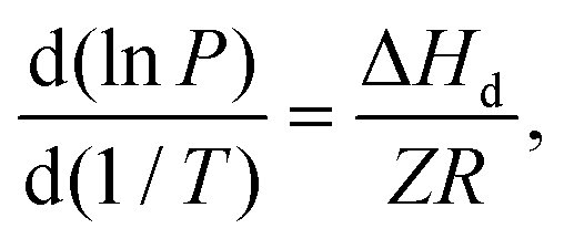
Provided the compressibility factor remains largely unchanged over the investigated three-phase equilibrium (equilibrium hydrate pressure and temperature) range, ΔHd can be estimated by multiplying the universal gas constant and the gas compressibility factor with the slope of the logarithm of hydrate equilibrium pressure plotted against the reciprocal of the hydrate equilibrium temperature.49Fig. 1c shows the Clausius–Clapeyron plot for four different methane hydrate systems, namely the pure CH4 system, the mixed CH4/DIOX system, the mixed CH4/THF system, and the mixed CH4/dioxane system. The four Clausius–Clapeyron plots shown in Fig. 1c are supplemented with their respective slopes. The heat of hydrate dissociation is calculated to be 59.3 kJ mol−1 for pure CH4 hydrate, 97.9 kJ mol−1 for mixed CH4/DIOX hydrate, 97.2 kJ mol−1 for mixed CH4/THF hydrate and 96.0 kJ mol−1 mixed CH4/dioxane hydrate. The dissociation heat of pure methane hydrate calculated presently agrees well with the available literature values.31 The change in the heat of hydrate dissociation predominantly depends on the crystal structure (sI, sII, and sH) of the gas hydrate regardless of the guest molecules. The closeness of the calculated heats of dissociation for the three mixed methane hydrate systems strongly indicates that the hydrate crystal structure formed is uniform across the three cases.
2.2. Optimization of mixed CH4/dioxane (5.56 mol%) hydrate formation kinetics at 283.2 K
Three independent hydrate formation experiments were first conducted for the simple “CH4/dioxane (5.56 mol%)” system at the experimental temperature of 283.2 K and the initial experimental pressure of 7.2 MPa using an unstirred tank reactor (UTR) setup. The detailed kinetic data for these three experiments is shown in Table S2 in the ESI† and the typical gas uptake profile obtained for one such experiment is presented currently as Fig. 2a. Each experiment was conducted for a fixed duration of 2 hours (post nucleation) with the final average volumetric CH4 storage capacity reaching 88.17 (±1.62) v/v, and the average time required to achieve 90% of the final volumetric gas storage capacity (t90) being 60.78 (±11.04) min. The gas hydrate synthesized at 283.2 K and 7.2 MPa using the “CH4/dioxane (5.56 mol%)” system was characterized by powder X-ray diffraction (p-XRD) technology (detailed procedure provided in the experimental section) and the resultant p-XRD spectrum is provided as Fig. 2b. As the thermodynamic equilibrium temperature for pure methane hydrate at the pressure of 7.2 MPa is 283.3 K,44 we are unlikely to form any pure methane (sI) hydrate under the aforementioned current experimental conditions. The same is confirmed through the p-XRD spectrum shown in Fig. 2b and Fig. S1 (ESI†) which exhibits a close match to other sII hydrate p-XRD patterns available in the literature.50–52 The sII hydrate peaks in Fig. 2b are labeled using their corresponding miller indices, with no sI hydrate peaks identified whatsoever. Detection of Ice Ih peaks in Fig. 2b is on expected lines, owing to the freezing of water vapor during sample preparation under liquid nitrogen temperature. The lattice parameter of the unit cell for the synthesized hydrate crystals is calculated to be 17.281 (±0.032) Å. Thus, it can be safely concluded that in the experiments performed presently using the mixed CH4/dioxane (5.56 mol%), only structure II (sII) mixed methane hydrates are synthesized. This in turn leads to the understanding that the average volumetric CH4 storage capacity achieved at the end of 2 hours of mixed CH4/dioxane hydrate growth is in fact 76.4% of the maximum theoretical limit, 115.36 v/v, for sII methane hydrate as calculated using the obtained lattice parameter of 17.281 (±0.032) Å. The above calculation is based on the scenario where dioxane alone occupies all the sII-51264 cages leaving only the sII-512 cages to be occupied by methane. The excellent hydrate growth kinetics observed for the “CH4/dioxane (5.56 mol%)” system establishes dioxane as an additive capable of providing both thermodynamic and kinetic enhancement to the process, thus placing it in the “dual-function promoter” class along with the likes of THF and DIOX. The fact that the experiments were conducted under unstirred tank reactor configuration, i.e., without the energy-intensive requirement of stirring the system adds another point in favour of developing a solidified natural gas technology based on the use of dioxane as a promoter. | ||
| Fig. 2 (a) A typical gas uptake profile obtained for hydrate formation conducted at 283.2 K temperature and 7.2 MPa initial pressure using the “CH4/dioxane (5.56 mol%)” system; (b) p-XRD pattern of mixed CH4/dioxane (5.56 mol%) hydrate synthesized at 283.2 K temperature and 7.2 MPa initial pressure; the asterisks (*) represents the ice (Ih) peaks. (c) Typical visual observation made through the front viewing window of the reactor for hydrate formation conducted at 283.2 K temperature and 7.2 MPa initial pressure using the “CH4/dioxane (5.56 mol%)” system. | ||
To provide the readers with a better understanding of the hydrate growth behavior for the “CH4/dioxane (5.56 mol%)” system, we present as Fig. 2c the visual observation of the reactor contents made through the front viewing window of the reactor during a typical mixed CH4/dioxane hydrate formation experiment. A video representing the same has been included in the ESI† as supporting Video SV1. Further, Fig. S2 (ESI†) presents the visual observation made through the top viewing window of the reactor during the same experiment. As observed in Fig. 2c(ii) and Fig. S2(ii) (ESI†), hydrate nucleation occurs at some point along the three phase interface (gas phase, liquid solution, and the inner reactor wall), located at the side of the reactor. Following the nucleation event, a thin layer of solid hydrate swiftly covers the entire gas–liquid interface (within 1 min as seen in Fig. 2c(iii)) and corroborated from Fig. S2(iii) (ESI†), representing the top view of the reactor contents at the (1 min mark post nucleation). During the first 7 min of hydrate growth (first 7 min following nucleation), there is some hydrate growth propagation downwards in the direction of the liquid phase (Fig. 2c(iii) and (iv)), however, the images of the top view of the reactor contents reveal that the preferred locations for hydrate growth are clearly the three-phase interfaces (intersection points of the liquid solution, the gas phase, and the solid inner wall of the reactor) and the solid surface of the thermocouple which is immersed in the liquid phase (Fig. S2(iii)–(v), ESI†). This behaviour can be attributed to the stainless steel surfaces having a lower actual temperature as compared to the surroundings, which provides a higher localized driving force to the system. When coupled with an ample supply of both solution and gas, these locations become hotspots for hydrate nucleation and growth. With time elapsed, the hydrate masses originating from the two sides of the reactor propagate inwards towards the centre of the reactor (Fig. 2c(v) and c(vi)). It is also observed through the top viewing window of the reactor that the flat and smooth hydrate layer covering the gas–liquid interface soon develops a complex, crumpled texture (Fig. S2(iv)–(vii), ESI†). The large propagating hydrate masses eventually merge at some stage beyond the 30 min mark in the hydrate growth process as evidenced from Fig. 2c(vii), (viii) and Fig. S2(xii) (ESI†). Any hydrate growth thereon is as a bulk solid and may be viewed in Video SV1 (ESI†).
Various concentrations (300 ppm, 1000 ppm, and 3000 ppm) of a known kinetic promoter, the amino acid L-tryptophan, were added to the 5.56 mol% dioxane aqueous solution to provide additional enhancement to the hydrate formation kinetics for experiments conducted under unstirred tank reactor configuration at 283.2 K and 7.2 MPa. L-Tryptophan was used in this work as it has previously been demonstrated to exhibit excellent kinetic promotion activity for both pure methane (sI) hydrate and mixed methane (sII) hydrate systems.39,42,45,53 The experimental hydrate formation data for the individual systems containing 300 pm, 1000 ppm, and 3000 ppm L-tryptophan is shown in Table S2 (ESI†). Fig. 3a presents a bar chart comparing the t90 and the volumetric CH4 storage capacity achieved at t90 for the system not containing any L-tryptophan and the individual systems containing L-tryptophan in various concentrations. The figure explicitly illustrates the kinetic promotion properties of L-tryptophan for mixed CH4/dioxane hydrate formation. Compared to the hydrate system without L-tryptophan, the presence of a minuscule amount (300 ppm) of this amino acid in the hydrate forming solution was able to significantly enhance the hydrate formation kinetics. Quantifiably, approximately 69% reduction was achieved in the average t90, from 60.78 (±11.04) min to 18.56 (±2.14) min, and a roughly eightfold enhancement was realized in the average hydrate formation rate (R15), from 0.52 (±0.16) v/v min−1 to 4.14 (±0.14) v/v min−1. However, this kinetic enhancement came at the cost of a noticeably reduced average methane storage capacity at t90, from 79.35 (±1.46) v/v to 61.89 (±1.52) v/v, which can be attributed to the fact that rapid hydrate growth and substantial water to hydrate conversion can quickly result in mass transfer limitations setting in, thereby stunting further hydrate growth. The hydrate formation kinetics was further improved by increasing the concentration of L-tryptophan to 1000 ppm but only to a limited extent. Specifically, compared to the counterpart system not containing L-tryptophan, the average t90 dropped to 14.78 (±0.84) min and the average volumetric methane storage capacity achieved at t90 is 66.68 (±2.13) v/v, while the average hydrate formation rate (R15) increased to 4.85 (±0.34) v/v min−1. Interestingly enough, increasing the concentration of L-tryptophan even further to 3000 ppm has no noticeable impact on the kinetics of mixed CH4/dioxane hydrate formation. The average t90 recorded in the presence of 3000 ppm L-tryptophan was 14.56 (±1.17) min, while the accompanying average volumetric methane storage capacity achieved at t90 and average hydrate formation rate were 67.13 (±2.38) v/v and 4.69 (±0.16) v/v min−1, respectively. Based on the balance between the kinetic promoting results obtained and the amount of kinetic promoter required, 1000 ppm is considered as the optimum L-tryptophan concentration for use as kinetic promoter for mixed CH4/dioxane (5.56 mol%) hydrate formation process. Fig. 3b exhibits the average gas uptake profile and standard deviation obtained from three individual experiments (PA4, PA5, and PA6) conducted at 283.2 K and 7.2 MPa using the “CH4/dioxane (5.56 mol%)/L-tryptophan (1000 ppm)” system. The final average volumetric CH4 storage capacity achieved is 74.09 (±2.36) v/v, which equates to 64.2% of the theoretical limit for mixed methane/dioxane (5.56 mol%) sII hydrate under the scenario that the methane molecules occupy only the sII-512 cages with the sII-51264 cages exclusively occupied by dioxane.
 | ||
| Fig. 3 (a) Comparison of the t90 and average gas uptake at t90 obtained for mixed CH4/dioxane (5.56 mol%) hydrate formation conducted in the presence of different concentrations of L-tryptophan (i.e. 0, 300, 1000, and 3000 ppm) at 283.2 K temperature and 7.2 MPa initial pressure; (b) average gas uptake profile and standard deviation obtained for hydrate formation conducted at 283.2 K temperature and 7.2 MPa initial pressure using the “CH4/dioxane (5.56 mol%)/L-tryptophan (1000 ppm)” system; (c) typical visual observation made through the front viewing window of the reactor mapping the hydrate growth for the “CH4/dioxane (5.56 mol%)/L-tryptophan (1000 ppm)” system at 283.2 K and 7.2 MPa. | ||
The hydrate growth behavior observed for the systems containing L-tryptophan remained largely unchanged for the various investigated promoter concentrations (300 ppm, 1000 ppm, and 3000 ppm). However, as compared to the system not containing any additional kinetic promoter, the hydrate growth behavior in the presence of L-tryptophan was completely different. Fig. 3c currently and Video SV2 in the ESI† show the typical hydrate growth morphology for the “CH4/dioxane (5.56 mol%)/L-tryptophan (1000 ppm)” system as observed via the front viewing window of the reactor; the same observation made through the top viewing window of the reactor is present in the ESI† as Fig. S3 and Video SV3. Similar to the system not containing any L-tryptophan, hydrate nucleation occurs at a certain point along the three-phase interface perimeter, i.e., the intersection of the gas phase, the liquid solution, and the solid inner wall of the reactor (see Fig. 3c(ii) and Fig. S3(ii), ESI†). Within a few seconds of nucleation, a thin wispy layer of hydrate covers the entire gas-liquid interface as noted in Fig. S3(iii) (ESI†). From Fig. S3(iii) (ESI†) it also becomes evident that the three-phase interface regions within the reactor (intersection points of the gas phase, liquid solution, and the solid inner wall of the reactor or the solid surface of the thermocouple) are the preferred locations for hydrate growth. This is plausibly due to the convergence of multiple favorable factors at these locations, namely a lower temperature on the surface of the steel material, and abundant availability of gas and hydrate forming solution. Notably, the subsequent hydrate growth behavior is significantly different from that observed for the system not containing any L-tryptophan (Fig. 2c and Fig. S2, ESI†). To elaborate, in Fig. 3c, up until the 3 min mark in the hydrate growth phase, hydrate masses can be seen propagating from the two sides of the reactor, inwards towards the centre of the reactor. However, instead of these hydrate masses simply merging at the center and growing as bulk solid hydrates thereon, Fig. S3(v) (ESI†) (3 min post nucleation) to Fig. S3(vii) (ESI†) (7 min post nucleation) reveal that in the presence of 1000 ppm L-tryptophan, hydrate growth propagation is significantly more pronounced in the vertically upward direction, i.e., in the direction of the gaseous phase. The same can be corroborated from Fig. 3c(vi), which represents the state of the reactor contents as observed via the front viewing window at the 7 min mark post nucleation. This is a trademark of amino acid promoted hydrate growth wherein the hydrate crystals formed tend to exhibit a distinct porous character (see Fig. 3c, Fig. S3 and Video SV2, ESI†), with the presence of hollow channels within the hydrate macrostructure.39,42 It is to this characteristic crystal morphology that the kinetic promotion activity of L-tryptophan is primarily attributed. The existence of hollow channels within the hydrate macrostructure enables both greater diffusion of gas into the liquid phase and the ability to draw up underlying unconverted solution to the surface of the existing hydrate layer to expose it to the overlying gas cap. The latter mechanism is better known as “capillary suction”.42 Essentially, what the presence of L-tryptophan offers is greatly enhanced gas-liquid contact which would have otherwise been stunted in a classical unstirred tank reactor operation. Our recently published review paper on amino acids as efficient kinetic hydrate promoters dives into greater detail on the possible mechanisms of action through which amino acids kinetically promote gas hydrate formation.54 Post the 15 min mark in the hydrate growth phase, the evolution in the hydrate morphology is negligible (Fig. 3c(vii), (viii) and Fig. S3(ix)–(xii), ESI†), thereby indicating near completion of hydrate growth within 15 min following hydrate nucleation and corroborating the methane uptake profile presented in Fig. 3b.
2.3. In situ Raman spectroscopic analysis of mixed CH4/dioxane (5.56 mol%) hydrates
Raman spectroscopy has been established as a robust and reliable tool to analyze the cage occupancy patterns of various hydrate guest molecules.55–60 Therefore, time-dependent in situ Raman spectroscopic measurements were performed in the present study for hydrate formation using the mixed CH4/dioxane (5.56 mol%) system. The obtained Raman spectrum was analyzed thoroughly to obtain insights into the hydrate structure formed, and more importantly, the evolving cage occupancy patterns of the two guest molecules.To eliminate Raman signal interference from methane molecules, the Raman spectroscopic analysis started with pure dioxane hydrates synthesized at 263.2 K solely using a 5.56 mol% dioxane solution, i.e. in the absence of any methane gas. Dioxane by itself is known to form sII hydrate, dioxane·17H2O, with the dioxane molecules by virtue of their large molecular size exclusively occupying the large (51264) cages, leaving the small cages (512) vacant.31,32Fig. 4a shows the Raman spectra obtained for a 5.56 mol% dioxane aqueous solution (in black), and for the dioxane hydrate synthesized at 263.2 K using the 5.56 mol% dioxane aqueous solution (in red). For both cases represented in Fig. 4a, the Raman peaks representing the C–H stretching modes of the dioxane molecules have been labeled explicitly; the peaks marked by the black arrows represent the Raman signals obtained from the dioxane molecules in solution whereas the peaks marked by the red arrows represent the Raman shifts that appear upon enclathration of the dioxane molecules within the large (51264) cages of sII hydrate. As evident in Fig. 4a, the C–H stretching modes of dioxane in the two obtained Raman spectra are noticeably different from each other. This is simply attributed to the different physical states that the dioxane molecules exist in before and after hydrate formation; prior to hydrate formation, the dioxane molecules are dissolved within the liquid solution whereas upon hydrate formation, the dioxane molecules are enclathrated within the solid hydrate phase. The prominent changes observed in the Raman spectrum (in the wavenumber range of 2600–3800 cm−1 – C–H and O–H stretching regions) upon pure dioxane hydrate formation include: (a) left shifts in the strong peaks at 2879 cm−1 and 2795.2 cm−1 for dioxane in aqueous solution, to 2851.2 cm−1 and 2782.4 cm−1 for dioxane in the hydrate phase, (b) a right shift in the strong peak at 2994.2 cm−1 for dioxane in aqueous solution, to 3006.7 cm−1 for dioxane enclathrated in hydrate, and (c) the emergence of two small peaks at 2966.9 cm−1 and 3048.6 cm−1, additional markers for dioxane in the hydrate phase that didn’t exist in the Raman spectrum obtained for the dioxane aqueous solution. Likewise, the change in the physical state of the water molecules upon hydrate formation is reflected by a noticeable change in the broad Raman band at 3100 to 3700 cm−1 representing the O–H stretching of water molecules.
 | ||
| Fig. 4 (a) Raman spectra obtained for both a 5.56 mol% dioxane aqueous solution (black) and pure dioxane hydrates (red) synthesized from 5.56 mol% dioxane aqueous solution at atmospheric pressure and 263.2 K; (b) Raman spectrum obtained upon completion of hydrate formation conducted at 283.2 K temperature and 7.2 MPa initial pressure using the “CH4/dioxane (5.56 mol%)” system – spectral coverage shown is in the wavenumber range of 2600–3700 cm−1 which signifies that the C–H stretching modes of both CH4 and dioxane molecules have been identified; (c) time-dependent Raman spectra obtained for the individual hydrate formation experiment (RNA1) conducted using the in situ Raman spectroscopy setup and the “CH4/dioxane (5.56 mol%)” system – experimental conditions employed were 283.2 K temperature and 7.2 MPa initial pressure; (d) time-dependent Raman spectra obtained for the individual hydrate formation experiment (RPA2) conducted using the in situ Raman spectroscopy setup and the “CH4/dioxane (5.56 mol%)/L-tryptophan (1000 ppm)” system – experimental conditions employed were at 283.2 K temperature and 7.2 MPa initial pressure. | ||
Fig. 4b shows the Raman spectrum obtained upon completion of hydrate formation using the mixed “CH4/dioxane (5.56 mol%)” system, at the experimental conditions of 283.2 K temperature and 7.2 MPa initial pressure. The spectral coverage in the figure is in the wavenumber range of 2600–3700 cm−1, which means that the C–H stretching modes of both methane and dioxane molecules upon mixed hydrate formation, have clearly been identified. Fig. 4b reaffirms the fact that the under the current experimental conditions, the mixed CH4/dioxane (5.56 mol%) system only forms sII hydrate. The strongest Raman peak observed in Fig. 4b is at 2911.8 cm−1, representing the C–H stretching of methane molecules trapped inside the small 512 cages of sII (mixed CH4/dioxane) hydrate. This agrees exceptionally well with the literature data available for methane occupancy in the sII-512 cages, albeit for other closely related hydrate systems.56,57 In total, eight Raman peaks (marked using blue arrows in Fig. 4b) were identified as the C–H stretching modes of dioxane molecules enclathrated in the large 51264 cages of sII (mixed CH4/dioxane) hydrate. These Raman markers for dioxane molecules incorporated within the solid hydrate phase present excellent consistency with those identified from the Raman spectrum obtained for pure dioxane (sII) hydrate (Fig. 4a).
Three independent hydrate formation experiments were conducted for the “CH4/dioxane (5.56 mol%)” system using the in situ Raman setup to obtain the dynamic cage occupancy patterns of the hydrate guest (methane and dioxane) molecules. These experiments were conducted in batch mode employing an unstirred tank reactor configuration at a temperature of 283.2 K and initial pressure of 7.2 MPa. The gas uptake profiles and associated kinetic data for the three mixed CH4/dioxane hydrate formation runs conducted using the in situ Raman setup are presented in the ESI† as part of Fig. S4 and Table S3 (ESI†), respectively. Fig. 4c presently, displays the typical time-dependent Raman spectra obtained for one of the experiments. As the Raman probe is located well within the aqueous (dioxane solution) phase and hydrate formation starts at some point along the three-phase (gas phase, liquid solution, and the inner wall of the reactor) interface (refer to Fig. 2c and Fig. S2, ESI†), the Raman probe does not detect the presence of the solid hydrate phase until ∼73 min post nucleation when the 2851.2 cm−1 and 2911.8 cm−1 peaks corresponding to dioxane in 51264 cages and CH4 in 512 cages, respectively, first begin to appear. It should be noted that for the experiments conducted using the in situ Raman spectroscopy setup, the sole marker for hydrate nucleation is the emergence of a sudden exothermic peak in the time-dependent temperature profile inside the reactor. With time elapsed, the two peaks at 2851.2 cm−1 and 2911.8 cm−1 continue to intensify while the intensity of the peak at 2879 cm−1 corresponding to dioxane in aqueous solution decreases (completely disappearing around the 86 min mark post nucleation). These trends highlight the ongoing phase change of the reactor contents from comprising only a liquid and a gas phase to also including a substantial quantity of solid hydrate. Finally, the obtained time dependent Raman spectra remain stable beyond the 130 min mark post nucleation, indicating near completion of the hydrate formation process by this time. The dynamic Raman spectra exhibited in Fig. 4c are also consistent with the sluggish gas uptake observed for mixed CH4/dioxane hydrate formation carried out using the in situ Raman spectroscopy setup, as evident from Fig. S4 in the ESI.†
The in situ Raman spectroscopic investigation was further extended for the “CH4/dioxane (5.56 mol%)/L-tryptophan (1000 ppm)” system, keeping the reactor configuration and experimental conditions constant. Three individual experimental runs were carried out with the system containing 1000 ppm L-tryptophan to ensure good repeatability. The gas uptake profiles and kinetic data for these three experiments have been included in the ESI† as part of Fig. S4 and Table S3 (ESI†), respectively. The present Fig. 4d shows the typical time-dependent Raman spectra obtained during mixed CH4/dioxane hydrate formation in the presence of 1000 ppm L-tryptophan. For this system, the presence of the solid hydrate phase inside the reactor is detected by the Raman probe ∼1.5 min after hydrate nucleation, with the intensity of the strong Raman peak at 2879 cm−1 representing C–H stretching of dioxane in aqueous solution dropping significantly, and simultaneous appearances of peaks at 2911.8 cm−1 and 2851.2 cm−1, representing CH4 occupancy in the sII-512 cages and dioxane occupancy in the sII-51264 cages, respectively. As hydrate growth continues, the intensity of the peak at 2879 cm−1 keeps on falling while the intensities of the peaks at 2911.8 cm−1 and 2851.2 cm−1 keep on increasing. The obtained Raman spectra remain essentially identical beyond the 15 min mark into the hydrate growth phase (Fig. 4d), indicating both near completion of the hydrate formation process within 15 min of hydrate nucleation and ultra-rapid hydrate growth in the presence of 1000 ppm L-tryptophan. The dynamic Raman spectra presented in Fig. 4d independently corroborate the excellent kinetic promotion performance of L-tryptophan for mixed CH4/dioxane hydrate formation.
2.4. Kinetic investigation into mixed CH4/dioxane (5.56 mol%) hydrate formation at elevated temperatures
Forming mixed CH4/dioxane (5.56 mol%) hydrate at 283.2 K still requires considerable energy to cool the whole setup against the ambient temperature (298.2 K). Therefore investigating mixed CH4/dioxane (5.56 mol%) hydrate formation at elevated temperatures is necessary to improve the economic feasibility of the hydrate formation process. Instead of an unstirred tank reactor configuration as in the case of the experiments conducted at 283.2 K, all the experiments conducted at temperatures above 283.2 K utilized a hybrid combinatorial reactor (HCR) approach in order to reduce the intrinsic stochasticity of hydrate nucleation.37 First, experiments were carried out at a temperature of 288.2 K and initial pressure of 9.7 MPa (initial pressure driving force of 7.6 MPa given the equilibrium pressure of mixed CH4/dioxane (5.56 mol%) hydrate at 288.2 K is 2.1 MPa). Two different hydrate forming systems were investigated at the aforementioned P–T conditions, (a) a “CH4/dioxane (5.56 mol%)” system (Case 1) and (b) a “CH4/dioxane (5.56 mol%)/L-tryptophan (1000 ppm)” system (Case 2). For Case 1, the average final volumetric methane storage capacity achieved is 98.78 (±1.63) v/v with 90% of gas uptake accomplished within 46.89 (±8.49) min (see Fig. 5a, b and Table S4, ESI†). The average gas uptake profiles and standard deviation for three experiments conducted using this system are presented in Fig. 5c as a blue line. A deflection point is observed around the 15 min mark into the hydrate growth phase beyond which the rate of methane uptake becomes sluggish. In contrast, the average gas uptake profile and standard deviation obtained for Case 2, i.e., the system containing 1000 ppm L-tryptophan as an additional kinetic promoter, presented in Fig. 5c as a red line, indicates a smooth and rapid gas uptake trend. Quantifiably, the presence of L-tryptophan leads to a 57% reduction in the average t90 to 19.56 (±0.38) min (see Fig. 5b). However, this comes at the cost of a slight reduction in the final gas uptake, with the average final volumetric methane storage capacity achieved being 91.84 (±1.68) v/v (see Fig. 5a). | ||
| Fig. 5 (a and b) Average volumetric methane storage capacity and t90 value achieved for various investigated hydrate systems; Case 1: “CH4/dioxane (5.56 mol%)” system, 288.2 K temperature and 9.7 MPa initial pressure; Case 2: “CH4/dioxane (5.56 mol%)/L-tryptophan (1000 ppm)” system, 288.2 K temperature and 9.7 MPa initial pressure; Case 3: “CH4/dioxane (5.56 mol%)” system, 293.2 K temperature and 12 MPa initial pressure; Case 4: “CH4/dioxane (5.56 mol%)/L-tryptophan (1000 ppm)” system, 293.2 K temperature and 12 MPa initial pressure; (c) average gas uptake profiles and standard deviations obtained for Case 1 and Case 2 experiments; (d) average gas uptake profiles and standard deviations obtained for Case 3 and Case 4 experiments. | ||
Next the experimental temperature was increased to 293.2 K and the initial experimental pressure to 12 MPa in order to maintain the same initial driving force of 7.6 MPa; the phase equilibrium pressure of mixed CH4/dioxane (5.56 mol%) hydrate at 293.2 K being ∼4.4 MPa. Three individual experiments were first conducted at the aforementioned P–T conditions simply using a 5.56 mol% dioxane solution, i.e., without the presence of any additional kinetic promotors (Case 3). The average volumetric methane storage capacity achieved for a fixed experimental run-time of 120 min is 106.98 (±0.71) v/v, which equates to 92.7% of the theoretical maximum (115.36 v/v) for sII methane hydrate, as discussed earlier. The average t90 achieved is 77.56 (±8.9) min (see Fig. 5a and b). With the temperature and initial pressure fixed at 293.2 K and 12 MPa respectively, when 1000 ppm L-tryptophan is added to the hydrate forming solution (Case 4), the average final volumetric methane storage capacity achieved is 106.80 (±0.52) v/v or 92.6% of the theoretical limit. This is a negligible drop of 0.1% compared to Case 3, however, what is important to note is that this gas uptake is accompanied by an average t90 of 53.78 (±2.04) min, an approximate 33% reduction compared to Case 3. This improvement in the gas uptake kinetics is a direct measure of the enhanced feasibility of the mixed CH4/dioxane (5.56 mol%) hydrate formation process obtained under an elevated temperature of 293.2 K with the introduction of a small amount (1000 ppm) of L-tryptophan into the system as an additional kinetic promoter. The average gas uptake profiles and standard deviations obtained for the experiments discussed in the present paragraph are shown in Fig. 5d, while the detailed kinetic data for the same is presented in Table S4 (ESI†). Further discussion on the different hydrate growth behaviors observed for the systems represented in Fig. 5, specifically Cases 3 and 4, is presented in the ESI.† Specifically Fig. S5 and its associated discussion in the ESI† deal with differences observed in the hydrate formation kinetics for representative Case 3 and Case 4 experiments, and Fig. S6 and its associated discussion in the ESI† deal with differences observed in the hydrate growth morphologies for representative Case 3 and Case 4 experiments.
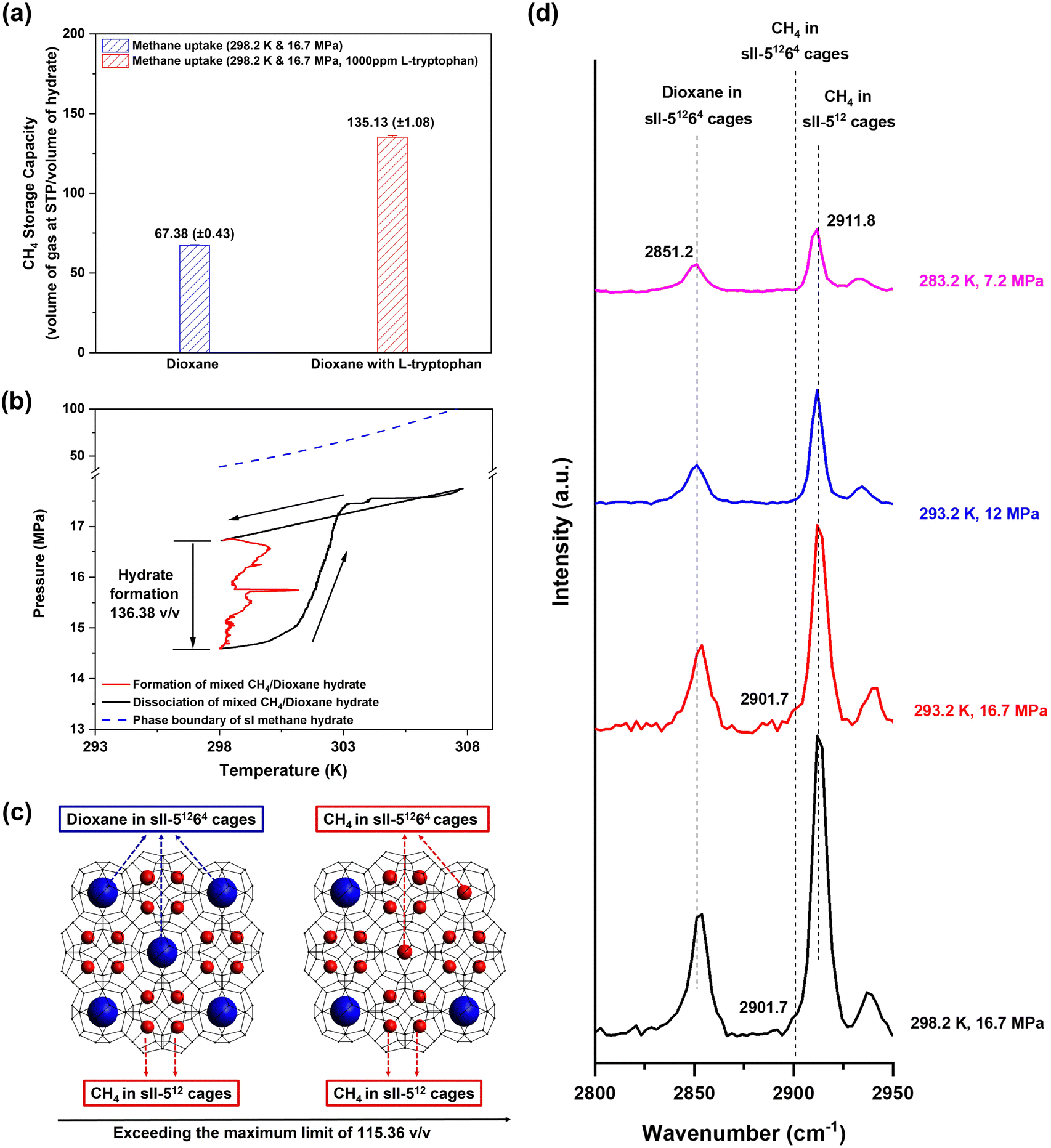
We concluded the elevated temperature study with hydrate formation experiments conducted at ambient temperature (298.2 K) and an initial pressure driving force of 7.6 MPa. As the equilibrium pressure of mixed CH4/dioxane (5.56 mol%) hydrate at 298.2 K is 9.1 MPa, to maintain an initial pressure driving force of 7.6 MPa, the initial experimental pressure employed was 16.7 MPa. Fig. 6a shows the average final volumetric methane storage capacities and standard deviations obtained for mixed CH4/dioxane (5.56 mol%) hydrate formation experiments conducted at 298.2 K temperature and 16.7 MPa initial pressure, using both an aqueous solution containing only dioxane (5.56 mol%), i.e., no additional kinetic promoters in the system (blue bar), and an aqueous solution containing both dioxane (5.56 mol%) and L-tryptophan (1000 ppm), the latter as a supplementary kinetic promoter (red bar). At ambient temperature (298.2 K), significant suppression of mixed CH4/dioxane (5.56 mol%) hydrate formation kinetics is observed with the average volumetric methane storage capacity achieved at the end of the experiments being 67.38 (±0.43) v/v. Our previous studies (available in the literature) indicate that in the absence of any kinetic promoter in the system, increasing the hydrate formation temperature to near-ambient values results in delayed nucleation and sluggish hydrate growth with the final gas storage capacity achieved at any given time being relatively lower, and thus, the aforementioned result is along expected lines.45,61 With the addition of 1000 ppm L-tryptophan to the system however, mixed CH4/dioxane (5.56 mol%) hydrate formation at ambient temperature (298.2 K) leads to a rather interesting and unusual observation. For the three experiments conducted at 298.2 K temperature and 16.7 MPa initial pressure in the presence of 1000 ppm L-tryptophan (kinetic data presented in Table S5 (ESI†)), the average final volumetric methane storage capacity and average t90 achieved are 135.13 (±1.08) v/v and 213.11 (±23.87) min, respectively. As the reader may recall from earlier sections of the manuscript, the maximum volumetric methane storage capacity possible for mixed CH4/dioxane (sII) hydrate is 115.36 v/v, which is based on the assumption that dioxane molecules occupy all the sII-51264 cages leaving only the sII-512 cages to be occupied by methane molecules. The average final volumetric methane storage capacity of 135.13 (±1.08) v/v achieved is thus unusual in that it well and truly exceeds the acknowledged limit for mixed CH4/dioxane (sII) hydrate. Given that the phase equilibrium pressure of pure methane (sI) hydrate at 298.2 K is 38.53 MPa (calculated using CSMHYD software), it is also improbable that under the currently employed experimental conditions of 298.2 K temperature and 16.7 MPa initial pressure, the “CH4/dioxane (5.56 mol%)/L-tryptophan (1000 ppm)” system forms sI methane hydrate (maximum volumetric methane storage capacity of 172 v/v) rather than sII, which could have otherwise explained the higher than expected final gas uptake achieved for this system.
 | ||
| Fig. 6 (a) Average final volumetric methane storage capacities and standard deviations obtained for the various experimental sets conducted with 16.7 MPa initial pressure: blue bar – “CH4/dioxane (5.56 mol%)” system at 298.2 K temperature; red bar – “CH4/dioxane (5.56 mol%)/L-tryptophan (1000 ppm)” system at 298.2 K temperature. (b) A typical pressure vs. temperature plot showing a formation and dissociation cycle for mixed CH4/dioxane (5.56 mol%) hydrate: the mixed CH4/dioxane (5.56 mol%) hydrate was formed at 298.2 K temperature and 16.7 initial pressure in the presence of 1000 ppm L-tryptophan as an additional kinetic promoter; the system temperature was then increased to 308 K to dissociate all the formed hydrate formed; finally, post complete hydrate dissociation, the system temperature was brought back down to the original starting temperature of 298.2 K. Given the high process temperatures involved, maintaining an unstirred system while lowering the temperature back down to 298.2 K was sufficient to ensure that there was no re-nucleation of hydrates during this process. Also shown in the figure is the phase boundary of pure CH4 (sI) hydrate, calculated using CSMHYD software, substantiating that only mixed CH4/dioxane (sII) hydrate may form under the current experimental pressure and temperature conditions. (c) A schematic illustrating the sII-51264 (large cage) occupancy by methane molecules. (d) Raman spectra obtained for mixed CH4/dioxane (5.56 mol%) hydrate samples synthesized at different experimental conditions; the mixed CH4/dioxane (5.56 mol%) hydrate samples were recovered using liquid nitrogen and the Raman spectra were measured ex situ, at atmospheric pressure and liquid nitrogen temperature. | ||
Fig. 6b shows a typical pressure vs. temperature plot obtained for a hydrate formation and dissociation experimental cycle performed using the “CH4/dioxane (5.56 mol%)/L-tryptophan (1000 ppm)”; hydrate formation was conducted at an experimental temperature of 298.2 K temperature and initial experimental pressure of 16.7 MPa (refer to the Fig. 6b caption for more details on the experimental procedure followed). It is clearly seen in Fig. 6b that the system temperature and pressure both recover to their respective starting points at the end of the hydrate formation and dissociation cycle, a firm confirmation that all of the gas uptake achieved is indeed due to hydrate formation and is not influenced in any part by the presence of leaks within the high-pressure system. The P–T curve presented in Fig. 6b also establishes straightforward recovery of the enclathrated gas upon hydrate dissociation. The experimental results for gas hydrate formation at ambient temperature (298.2 K) and 16.7 MPa initial pressure using the “CH4/dioxane (5.56 mol%)/L-tryptophan (1000 ppm)” system turn out to be highly repeatable, as reflected by the average final volumetric methane storage capacity and standard deviation (obtained from three individual runs) presented in Fig. 6a, and the detailed kinetic data for the three individual experiments provided in Table S5 (ESI†).
Fig. 6c is a schematic illustration used to explain the unnaturally high methane storage capacity achieved for hydrate formation at ambient temperature using the “CH4/dioxane (5.56 mol%)/L-tryptophan (1000 ppm)” system. As per the schematic, we hypothesize a situation where methane molecules occupy both sII-512 and sII-51264 cages. While methane molecules are still recognized to occupy all the available sII-512 cages, under the proposed hypothesis, methane molecules would also occupy 34.27% of the sII-51264 cages for a total volumetric methane storage capacity of 135.13 v/v. The phenomenon of methane and dioxane molecules competing to occupy the sII-51264 cages may well be a consequence of two system-specific factors teaming up, (a) the high initial pressure of 16.7 MPa employed which can also be interpreted as an exceedingly high concentration of methane molecules introduced into the reaction scheme and (b) the presence of a highly effective kinetic promoter for methane hydrate formation, L-tryptophan, in the aqueous hydrate forming solution. However, further work is required to substantiate this supposition. To strengthen the case that the volumetric methane storage capacity for mixed CH4/dioxane (5.56 mol%) sII hydrate may exceed the previously understood limit of 115.36 v/v, we conducted CH4 hydrate formation experiments using an aqueous solution containing 5.56 mol% dioxane and 1000 ppm L-tryptophan, at 293.2 K temperature and 16.7 MPa initial pressure (initial driving force of 12.3 MPa). Under these thermodynamic conditions the possibility of forming sI methane hydrate does not exist as the equilibrium pressure for pure methane (sI) hydrate at 293.2 K is 21.28 MPa (calculated using CSMHYD software). As observable from Table S5 (ESI†), the average final volumetric methane storage capacity obtained for hydrate formation experiments (three individual runs) using the “CH4/dioxane (5.56 mol%)/L-tryptophan (1000 ppm)” system at 293.2 K temperature and 16.7 MPa initial pressure is 131.22 (±1.03) v/v, which implies occupancy of 27.48% of the sII-51264 cages by methane molecules. Further, the average t90 value obtained for this set of experiments is 87.44 (±5.97), a ∼59% reduction compared to that obtained at 298.2 K temperature and 16.7 MPa initial pressure using the same system. It is evident that with the initial pressure being fixed at 16.7 MPa, the higher initial driving force available at 293.2 K boosts the rate of gas uptake within the solid hydrate phase. Finally, computational calculations presented by Frankcombe and Kroes62 indicate that there is only an insignificant difference in the “guest–clathrate interaction energies” between methane occupancy in sII-512 and methane occupancy in sII-51264 cages. The logical conclusion to be drawn from this information is a low likelihood of a significant drop in the stability of sII methane hydrate if, in addition to all of the sII-512 (small) cages, methane molecules also occupied a certain percentage of the sII-51264 (large) cages. As stated prior, our experimental observations indicate that in the present study, for the mixed CH4/dioxane (5.56 mol%) sII hydrate system, the percentage occupancy of the sII-51264 (large) cages is 27.48% at the experimental conditions of 293.2 K temperature and 16.7 MPa pressure, and 34.27% at the experimental conditions of 298.2 K temperature and 16.7 MPa pressure. Combined, the results discussed in the current and the preceding two paragraphs open up possibilities where the experimental pressure and temperature conditions may be tuned to maximize the feasibility (gas uptake rate and final gas storage capacity) of mixed methane (sII) hydrate formation in the presence of dioxane and other similar dual-function promoters. The use of lower concentrations of these dual-function promoters in solution may also be explored which would free up additional hydrate cages that may instead be occupied by CH4 molecules.
It is also interesting to note that while the average final volumetric methane storage capacity decreases slightly with the addition of the kinetic promoter L-tryptophan under the relatively moderate hydrate formation temperatures of 283.2 K and 288.2 K, as the hydrate formation temperature moves up into the near-ambient (293.2 K) and ambient (298.2 K) range, this issue attains a natural resolution. At the experimental temperature of 293.2 K, the average final volumetric methane storage capacity achieved for the system not containing any L-tryptophan exceeds that achieved for the system containing 1000 ppm L-tryptophan by a negligible 0.17%, whereas at the experimental temperature of 298.2 K, the average final volumetric methane storage capacity achieved for the system not containing any L-tryptophan is less than half that achieved for the system containing 1000 ppm L-tryptophan. Thus, we see the emergence of a trend wherein the higher the hydrate formation temperature, the more pronounced the impact of the kinetic promoter L-tryptophan appears to be. These observations also highlight the importance of including an efficient kinetic promoter in the system when concerned with methane hydrate formation at elevated temperatures.
2.5. Raman spectroscopic analysis of mixed CH4/dioxane (5.56 mol%) hydrates synthesized at elevated temperatures
The idea of CH4 molecules occupying the sII-51264 cages is not one that is completely novel to the literature. Both, Subramanian et al.57 and Seo et al.63 have reported the presence of methane molecules in the sII-51264 cages for their respective investigated hydrate systems, CH4/THF-d8 (deuterated) mixed hydrate system and CH4 (mole fraction ≥0.750 and above)/C2H6 mixed hydrate system in the case of Subramanian et al.57 and CH4/THF mixed hydrate system in the case of Seo et al.63 Analysis of a mixed methane sII hydrate sample to distinguish methane occupancy in the small (512) cages and large (51264) cages is not straightforward. However, Raman spectroscopy has proved to be an efficient tool in this regard. For instance, in the case of mixed CH4/THF sII hydrate, both Subramanian et al.57 and Seo et al.63 were able to establish a 10 cm−1 difference in the wavenumbers where the Raman peaks appear for methane molecules enclathrated within the sII-512 and sII-51264 cages. Further, Sum et al.56 suggested that the asymmetric Raman peak shape of deuterated methane (CD4) obtained for mixed CD4/C3H8 sII hydrate was a result of a small amount of CD4 residing in the sII-51264 cages of the mixed hydrate.As the maximum operating pressure of the Raman probe at our disposal is about 12 MPa, in situ Raman spectroscopic analysis of mixed CH4/dioxane (5.56 mol%) hydrate formation starting at a pressure of 16.7 MPa could not be conducted. Instead, an ex situ approach was followed: mixed CH4/dioxane (5.56 mol%) hydrate was first synthesized at 16.7 MPa using a conventional kinetic setup, followed by recovery of the hydrate sample using liquid nitrogen to avoid dissociation, and finally, Raman spectroscopic measurement of the recovered hydrate sample at liquid nitrogen temperature (refer to Section S1.2.3 in the ESI† for more details on the procedure followed). Fig. 6d presents the analysis of the Raman spectra obtained for mixed CH4/dioxane (5.56 mol%) hydrate formed at different P–T conditions; this includes the analysis obtained for mixed CH4/dioxane (5.56 mol%) synthesized at the high pressure of 16.7 MPa, as well as the analysis obtained for mixed CH4/dioxane (5.56 mol%) synthesized at lower pressure conditions. For consistency in measurements and accurate analysis, ex situ Raman spectra, following the process described above, were obtained even for mixed CH4/dioxane (5.56 mol%) hydrates synthesized at lower pressures. The Raman spectrum obtained for mixed CH4/dioxane (5.56 mol%) hydrate synthesized either at 293.2 K and 12 MPa or at 283.2 K and 7.2 MPa presents a smooth and near-symmetric peak at 2911.8 cm−1, indicating methane occupancy in the sII-512 cages only. However, the individual Raman spectra obtained for mixed CH4/dioxane (5.56 mol%) hydrate synthesized at 16.7 MPa and two different temperatures of 293.2 K and 298.2 K exhibit a noticeable shoulder around 2901.7 cm−1 making the Raman peak at 2911.8 cm−1 markedly asymmetric (see Fig. S7, ESI†). The distinct shoulder at 2901.7 cm−1 is attributed to C–H stretching of methane molecules trapped inside the sII-51264 cages and this assignment is consistent with the general trend observable from the literature that the Raman peak representing large cage occupancy by CH4 molecules appears at a lower wavenumber as compared to its counterpart representing small cage occupancy by CH4 molecules. To summarize, by applying high experimental pressure (16.7 MPa) at elevated temperatures (293.2 K and 298.2 K), using dioxane in stoichiometric concentration (5.56 mol%) as a dual-function promoter, and employing L-tryptophan (1000 ppm) as an additional kinetic promoter, a breakthrough has been achieved in the gas uptake limits for mixed methane (sII) hydrate, wherein methane molecules occupy up to 34.27% of the sII-51264 cages in addition to occupying all of the sII-512 cages. This translates to a volumetric methane storage capacity of 135.13 (±1.08) v/v, far surpassing the previously understood maximum (115.36 v/v) for mixed CH4/dioxane (5.56 mol%) sII hydrate based on complete occupancy of methane in small cages.
2.6. Stability analysis of mixed CH4/dioxane (5.56 mol%) hydrates
Understanding the stability characteristics of methane or natural gas hydrate systems is critical towards developing a practicable SNG technology. Accordingly, stability testing was conducted for mixed CH4/dioxane (5.56 mol%) hydrate stored under near atmospheric pressure and 268.2 K (target) temperature. Based on the phase equilibrium curve for the mixed CH4/dioxane (5.56 mol%) hydrate system presented in Fig. 1(b), we expect mixed CH4/dioxane (5.56 mol%) hydrate to be thermodynamically stable, i.e., lie within its three-phase equilibrium boundary at atmospheric pressure and 268.2 K temperature. Thus, there is no reliance on the self-preservation phenomenon in the present work.For the stability test, first, mixed CH4/dioxane hydrates were synthesized using an aqueous solution containing 5.56 mol% dioxane and 1000 ppm L-tryptophan, the experimental temperature and initial pressure employed being 283.2 K and 7.2 MPa, respectively. Next, the synthesized hydrate particles were pelletized into a compact cylindrical shape using a one-of-a-kind, patented SNG technology prototype (for the detailed description of this setup and the procedure followed for hydrate synthesis and pelletization, the reader is referred to the “Methods” section in the ESI†). The produced cylindrical hydrate pellet having a diameter of 50 mm, length of 43 mm, and weight of 74.05 g (see inset of Fig. 7) was then transferred to a storage vessel that had been pre-cooled using liquid nitrogen. Finally, the storage vessel was closed, its lid tightly fastened, and the entire affair, i.e., the storage vessel containing the hydrate pellet, isolated in a conventional laboratory freezer (maintained at the desired storage temperature of 268.2 K) for 4 months (120 days) of stability testing. Hydrate pellet transfer into the storage vessel, measurements of hydrate pellet dimensions and weight, and sealing of the storage vessel containing the hydrate pellet all took place under atmospheric pressure condition. A thermocouple and pressure transducer located on the lid of the storage vessel and connected to a data logger were used to monitor temperature and pressure changes within the storage vessel, respectively. Any dissociation of hydrates would lead to the stored gas being evolved into the closed storage vessel, thus resulting in an increase in the internal pressure of the same.
 | ||
| Fig. 7 Evolution of the pressure and temperature within a storage vessel during stability testing of a mixed CH4/dioxane (5.56 mol%) hydrate pellet stored under near atmospheric pressure and a moderate average temperature (268.3 (±0.2) K) for 120 days. The inset shows the diameter, height, and weight of the synthesized hydrate pellet. | ||
Fig. 7 represents the time dependent evolution of the pressure and temperature within the storage vessel for the entirety of the 4 month (120 days) stability test. As seen in the figure, both the temperature and pressure inside the storage vessel remained largely unchanged throughout the entire hydrate storage period. Specifically, the average pressure and temperature readings inside the storage vessel over 4 months of stability testing stood at 146.9 (±4.5) kPa (gauge pressure) and 268.3 (±0.2) K, respectively. The total pressure change within the storage vessel during this period was a negligible 14.5 kPa (gauge pressure), increasing from 135.2 kPa (gauge pressure) when the test first commenced to 149.7 kPa (gauge pressure) when the test was finally deemed to be completed. The constant temperature profile observed in Fig. 7 is expected as the stability test was conducted within a temperature-controlled setting, i.e. the interior of a conventional laboratory freezer. However, the pressure profile presented in Fig. 7 (also an overall constant trend; negligible pressure increase of 14.5 kPa (gauge pressure) over 120 days) has a far greater significance being a clear indicator of the remarkable, sustained stability of the mixed CH4/dioxane (5.56 mol%) hydrate pellet when stored under near-atmospheric pressure and a moderate average temperature of 268.3 (±0.2) K.
Notably, in Fig. 7, the pressure in the storage vessel (135.2 kPa (gauge pressure)) at the start of the stability test was already very close to the average value of 146.9 (±4.5) kPa (gauge pressure) observed over the 4 months of stability testing. As the storage vessel containing the hydrate pellet was sealed at atmospheric pressure and no external pressure was supplied to the same during the entire stability test period, the slightly excess pressure indication at the start of the test can only be attributed to the hydrate pellet being outside its thermodynamic stability zone when it was first moved into storage. Even a slightly unstable hydrate pellet can lead to some gas evolution inside the storage vessel prior to the pellet regaining its thermodynamic stability. To the best of our understanding, the primary cause behind the slight instability carried by the hydrate pellet when first moved into storage is heat transfer losses experienced in the course of hydrate pelletization and transfer, especially during the experimentally limited operations of measuring the pellet's weight and dimensions and sealing into the storage vessel.
2.7. Economic considerations for the SNG technology
In the Introduction section, we specify that the SNG technology proposed in the present study is intended for ‘long-term’ and ‘large-scale’ stationary natural gas storage application. Given the drawbacks of LNG (extreme low-temperature requirement and continuous boil-off of stored gas)12 and CNG (explosive nature owing to high pressure requirement)11 for long-term and large-scale natural gas storage, respectively, the SNG technology, as an option for long-term backup power presents the potential for expeditious adoption into nations’ energy resilience frameworks. Even Adsorbed Natural Gas (ANG), another upcoming natural gas storage technique which has received significant attention in the past only from the on-board storage point of view64 is not considered conducive for long-term, and large-scale stationary natural gas storage. The primary reason is that ANG-based technologies need the same adsorbed pressure for storage resulting in high design cost and safety considerations for the storage vessels, similar to that experienced with CNG.4 The fact that an SNG technology based on the formation and storage of mixed methane (sII) hydrate enables safe, long-term storage of natural gas under atmospheric or near-atmospheric pressures and moderate temperatures (∼268.2 K as demonstrated in the present study), is, therefore, a critical advantage in favour of the technology over its competitors.From an economic standpoint, for large-scale stationary natural gas storage application, the major contributor to the expenses is expected to be capital costs (CAPEX) for infrastructure development, primarily building the industrial-scale storage tanks to house the natural gas or natural gas containing materials. The potential options of CNG, ANG, and SNG, all entail the utilization of pressure-tight vessels to physically accomplish the storage of natural gas. In this regard, the literature significantly suggests that the stainless-steel storage vessels required to store methane as CNG or ANG (pressure rating of 7.5 MPa) are more than 5.5 times as expensive as those required to store methane as SNG—sII mixed hydrates (pressure rating of 1.0 MPa).42 Further, the SNG technology employs water as the main component of the hydrate forming solution (>94 mol%), generally with two additional small quantities of well-known chemical additives as promoters.42 The result is a technology significantly more economical from a raw materials perspective in comparison to ANG-based technologies, wherein the synthesis of methane gas adsorbents necessitates employing expensive building-block materials and lengthy multi-step processes, often with no established scale-up methods.4
A high gas storage capacity is paramount for any natural gas technology to be economically feasible. The SNG technology is well placed in this regard and the acknowledged volumetric methane storage capacity limit for mixed methane (sII) hydrate systems containing a stoichiometric amount of a thermodynamic or dual-function promoter, is about 115.36 v/v.13 The results obtained in the present study establish that at certain experimental conditions, the volumetric methane storage capacity for mixed methane (sII) hydrates can in fact be increased beyond the acknowledged limit. At a hydrate formation temperature of 298.2 K and initial pressure of 16.7 MPa, a breakthrough final volumetric methane storage capacity of 135.13 (±1.08) v/v was reported for the “CH4/dioxane (5.56 mol%)/L-tryptophan (1000 ppm)” system. This corresponds to methane molecules occupying 34.27% of the sII-large (51264) cages in addition to all of the sII-small (512) cages demonstrating tunability of methane in the large cages. There does exists the possibility that this tunability may be enhanced even further; however, as it is not explicitly known up to what extent the sII-large (51264) cages may be filled with methane molecules, it is very difficult to set a practical target value or limit for the final methane storage capacity that may achieved using the sII mixed hydrate approach. As a reference, given the assumption that all of the sII-small (512) cages are filled with methane molecules, additional 50%, 60%, and 75% occupancy of the sII-large (51264) cages by methane molecules correspond to total methane storage capacities of 144.20 v/v, 149.97 v/v, and 158.62 v/v, respectively. Follow-up works will focus on innovations and upgradations to our methodologies and experimental designs to reach as close to these values as possible.
3. Conclusion
Dioxane is identified as a dual function (thermodynamic and kinetic) promoter for methane hydrate formation for the first time. A 5.56 mol% dioxane aqueous solution provided significant thermodynamic promotion for methane hydrate formation and storage as demonstrated by the extensive phase equilibrium condition (52 data points in total) obtained for mixed CH4/dioxane (5.56 mol%) hydrate. Ultra-rapid formation of mixed CH4/dioxane was realized under unstirred tank reactor configuration. Up to 135.13 (±1.08) v/v gas uptake was achieved for sII methane hydrates at room temperature. Key evidence was obtained regarding the tunability of the storage capacity of sII methane hydrate employing optimized formation (pressure and temperature) conditions and the kinetic promoter L-tryptophan. This breakthrough methane storage capacity achieved is owed to CH4 molecules occupying 34.27% of the sII-51264 cages in addition to occupying all the sII-512 cages. Finally, a mixed CH4/dioxane (5.56 mol%) hydrate stored at near-atmospheric pressure in a tightly sealed container for 120 days exhibited excellent stability. The current fundamental findings convincingly lay down the potential to develop a dioxane promoted SNG technology for large-scale, environmentally conscious deployment, and should be of great interest to researchers working on similar lines.4. Materials and methods
All the materials, experimental procedures, and data process methods are in the ESI.†Author contributions
PL supervised the project. PL, YZ, and GB conceptualized the work and designed the experiments. YZ and JZ carried out the phase equilibrium and kinetic experiments. YZ and HX carried out the kinetic experiments at elevated temperatures. YZ carried out the pXRD, in situ Raman characterization and the stability test of hydrate pellet. YZ wrote the original manuscript draft. GB, PL, RK, and MY edited the manuscript and contributed to the final version. All authors read the final manuscript and consented to the submission.Conflicts of interest
There are no conflicts of interest to declare.Acknowledgements
The authors acknowledge the funding support from MoE (A-0009533-01-00) and the National University of Singapore. Jie Zhao acknowledges the support of the state scholarship fund from the China Scholarship Council (CSC202006060161).References
- K. Huang, J. B. Miller, G. W. Huber, J. A. Dumesic and C. T. Maravelias, Joule, 2018, 2, 349–365 CrossRef CAS.
- J. A. Mason, J. Oktawiec, M. K. Taylor, M. R. Hudson, J. Rodriguez, J. E. Bachman, M. I. Gonzalez, A. Cervellino, A. Guagliardi, C. M. Brown, P. L. Llewellyn, N. Masciocchi, J. R. Long and A. I. L. A. P. S. Argonne National Lab, Nature, 2015, 527, 357–361 CrossRef CAS PubMed.
- C. M. Simon, J. Kim, D. A. Gomez-Gualdron, J. S. Camp, Y. G. Chung, R. L. Martin, R. Mercado, M. W. Deem, D. Gunter, M. Haranczyk, D. S. Sholl, R. Q. Snurr, B. Smit, B. C. A. Lawrence Berkeley National Lab and M. M. N. N. M. G. C. Univ. of Minnesota, Energy Environ. Sci., 2015, 8, 1190–1199 RSC.
- V. Rozyyev, D. Thirion, R. Ullah, J. Lee, M. Jung, H. Oh, M. Atilhan and C. T. Yavuz, Nat. Energy, 2019, 4, 604–611 CrossRef CAS.
- N. Mac Dowell, N. Sunny, N. Brandon, H. Herzog, A. Y. Ku, W. Maas, A. Ramirez, D. M. Reiner, G. N. Sant and N. Shah, Joule, 2021, 5, 2524–2529 CrossRef CAS.
- A. Majumdar, J. M. Deutch, R. S. Prasher and T. P. Griffin, Joule, 2021, 5, 1905–1908 CrossRef.
- IEA (2011), World Energy Outlook 2011, IEA, https://iea.blob.core.windows.net/assets/8caa3d14-5005-437d-b180-06b8824d28c8/WEO2011_GoldenAgeofGasReport.pdf.
- IEA (2013), Golden Rules for a Golden Age of Gas, IEA, Paris, https://www.iea.org/reports/golden-rules-for-a-golden-age-of-gas.
- Y.-S. Yu, X. Zhang, J.-W. Liu, Y. Lee and X.-S. Li, Energy Environ. Sci., 2021, 14, 5611–5668 RSC.
- R. Boswell and T. S. Collett, Energy Environ. Sci., 2011, 4, 1206–1215 RSC.
- M. I. Khan, T. Yasmin and A. Shakoor, Renewable Sustainable Energy Rev., 2015, 51, 785–797 CrossRef CAS.
- S. Mokhatab, J. Y. Mak, J. Valappil and D. A. Wood, Handbook of liquefied natural gas, Gulf Professional Publishing, 2013 Search PubMed.
- H. P. Veluswamy, A. Kumar, Y. Seo, J. D. Lee and P. Linga, Appl. Energy, 2018, 216, 262–285 CrossRef CAS.
- W. Wang, C. L. Bray, D. J. Adams and A. I. Cooper, J. Am. Chem. Soc., 2008, 130, 11608–11609 CrossRef CAS.
- F. Ning, Y. Yu, S. Kjelstrup, T. J. H. Vlugt and K. Glavatskiy, Energy Environ. Sci., 2012, 5, 6779–6795 RSC.
- Z. R. Chong, S. H. B. Yang, P. Babu, P. Linga and X. S. Li, Appl. Energy, 2016, 162, 1633–1652 CrossRef.
- P. L. Stanwix, N. M. Rathnayake, F. P. P. de Obanos, M. L. Johns, Z. M. Aman and E. F. May, Energy Environ. Sci., 2018, 11, 1828–1840 RSC.
- E. D. Sloan, Nature, 2003, 426, 353–363 CrossRef CAS.
- S. Denning, A. A. A. Majid, J. M. Lucero, J. M. Crawford, M. A. Carreon and C. A. Koh, ACS Appl. Mater. Interfaces, 2020, 12, 53510–53518 CrossRef CAS.
- P. Di Profio, V. Canale, N. D’Alessandro, R. Germani, A. Di Crescenzo and A. Fontana, ACS Sustainable Chem. Eng., 2017, 5, 1990–1997 CrossRef CAS.
- W. L. Mao, H.-k Mao, A. F. Goncharov, V. V. Struzhkin, Q. Guo, J. Hu, J. Shu, R. J. Hemley, M. Somayazulu and Y. Zhao, Science, 2002, 297, 2247–2249 CrossRef CAS.
- D. Y. Kim and H. Lee, J. Am. Chem. Soc., 2005, 127, 9996–9997 CrossRef CAS.
- L. J. Florusse, C. J. Peters, J. Schoonman, K. C. Hester, C. A. Koh, S. F. Dec, K. N. Marsh and E. D. Sloan, Science, 2004, 306, 469–471 CrossRef CAS.
- R. Kumar, D. D. Klug, C. I. Ratcliffe, C. A. Tulk and J. A. Ripmeester, Angew. Chem., 2013, 125, 1571–1574 CrossRef.
- H. Lee, J. W. Lee, D. Y. Kim, J. Park, Y. T. Seo, H. Zeng, I. L. Moudrakovski, C. I. Ratcliffe and J. A. Ripmeester, Nature, 2005, 434, 743–746 CrossRef CAS PubMed.
- Y.-S. Yu, Q.-Z. Zhang, X.-S. Li, C. Chen and S.-D. Zhou, Appl. Energy, 2020, 265, 114808 CrossRef CAS.
- J. Cai, Y. Q. Tao, N. von Solms, C. G. Xu, Z. Y. Chen and X. S. Li, Appl. Energy, 2019, 243, 1–9 CrossRef CAS.
- Y. Zhang, G. Bhattacharjee, R. Kumar and P. Linga, Chem. Eng. J., 2021, 133702, DOI:10.1016/j.cej.2021.133702.
- Y. Zhang, G. Bhattacharjee, J. Zheng and P. Linga, Chem. Eng. J., 2022, 427, 131771 CrossRef CAS.
- P. Di Profio, V. Canale, R. Germani, S. Arca and A. Fontana, J. Colloid Interface Sci., 2018, 516, 224–231 CrossRef CAS.
- E. D. Sloan Jr and C. A. Koh, Clathrate hydrates of natural gases, CRC Press, 2007 Search PubMed.
- P. Englezos, Ind. Eng. Chem. Res., 1993, 32, 1251–1274 CrossRef CAS.
- H. P. Veluswamy, A. J. H. Wong, P. Babu, R. Kumar, S. Kulprathipanja, P. Rangsunvigit and P. Linga, Chem. Eng. J., 2016, 290, 161–173 CrossRef CAS.
- L. A. Stern, S. Circone, S. H. Kirby and W. B. Durham, J. Phys. Chem. B, 2001, 105, 1756–1762 CrossRef CAS.
- L. A. Stern, S. Circone, S. H. Kirby and W. B. Durham, Energy Fuels, 2001, 15, 499–501 CrossRef CAS.
- L. A. Stern, S. Circone, S. H. Kirby and W. B. Durham, J. Phys. Chem. B, 2002, 106, 228–230 CrossRef CAS.
- H. P. Veluswamy, A. Kumar, R. Kumar and P. Linga, Appl. Energy, 2017, 188, 190–199 CrossRef CAS.
- A. Kumar, H. P. Veluswamy, R. Kumar and P. Linga, Appl. Energy, 2019, 235, 21–30 CrossRef CAS.
- G. Bhattacharjee, H. Prakash Veluswamy, R. Kumar and P. Linga, Appl. Energy, 2020, 269, 115142 CrossRef CAS.
- G. Bhattacharjee, H. P. Veluswamy, A. Kumar and P. Linga, Chem. Eng. J., 2021, 415, 128927 CrossRef CAS.
- F. Mackinson, NIOSH/OSHA, 1981, 81–123.
- G. Bhattacharjee, M. N. Goh, S. E. K. Arumuganainar, Y. Zhang and P. Linga, Energy Environ. Sci., 2020, 13, 4946–4961 RSC.
- A. Venkateswaran, J. Easterfield and D. Davidson, Can. J. Chem., 1967, 45, 884–886 CrossRef CAS.
- Y. Zhang, G. Bhattacharjee and P. Linga, Fluid Phase Equilib., 2021, 540, 113034 CrossRef CAS.
- Y. Zhang, G. Bhattacharjee, M. Dharshini Vijayakumar and P. Linga, Appl. Energy, 2022, 311, 118678 CrossRef CAS.
- L.-T. Li, Y.-P. Chen and M. Tang, J. Chem. Eng. Data, 2019, 65, 177–184 CrossRef.
- Y.-J. Lee, T. Kawamura, Y. Yamamoto and J.-H. Yoon, J. Chem. Eng. Data, 2012, 57, 3543–3548 CrossRef CAS.
- Y. P. Handa, J. Chem. Thermodyn., 1986, 18, 915–921 CrossRef CAS.
- E. D. Sloan and F. Fleyfel, Fluid Phase Equilib., 1992, 76, 123–140 CrossRef CAS.
- W. Shin, S. Park, H. Ro, D. Y. Koh, J. Seol and H. Lee, J. Chem. Thermodyn., 2012, 44, 20–25 CrossRef CAS.
- T. C. W. Mak and R. K. McMullan, J. Chem. Phys., 1965, 42, 2732–2737 CrossRef.
- M. T. Kirchner, R. Boese, W. E. Billups and L. R. Norman, J. Am. Chem. Soc., 2004, 126, 9407–9412 CrossRef CAS PubMed.
- H. P. Veluswamy, P. Y. Lee, K. Premasinghe and P. Linga, Ind. Eng. Chem. Res., 2017, 56, 6145–6154 CrossRef CAS.
- G. Bhattacharjee and P. Linga, Energy Fuels, 2021, 35, 7553–7571 CrossRef CAS.
- C. A. Tulk, D. D. Klug and J. A. Ripmeester, J. Phys. Chem. A, 1998, 102, 8734–8739 CrossRef CAS.
- A. K. Sum, R. C. Burruss and E. D. Sloan, J. Phys. Chem. B, 1997, 101, 7371–7377 CrossRef CAS.
- S. Subramanian, R. A. Kini, S. F. Dec and E. D. Sloan Jr, Chem. Eng. Sci., 2000, 55, 1981–1999 CrossRef CAS.
- J. Wang, H. Lu, J. A. Ripmeester and U. Becker, J. Phys. Chem. C, 2010, 114, 21042–21050 CrossRef CAS.
- J. Wang, H. Lu and J. A. Ripmeester, J. Am. Chem. Soc., 2009, 131, 14132–14133 CrossRef CAS PubMed.
- T. A. Strobel, E. D. Sloan and C. A. Koh, J. Chem. Phys., 2009, 130, 014506 CrossRef.
- H. P. Veluswamy, S. Kumar, R. Kumar, P. Rangsunvigit and P. Linga, Fuel, 2016, 182, 907–919 CrossRef CAS.
- T. J. Frankcombe and G.-J. Kroes, Phys. Chem. Chem. Phys., 2011, 13, 13410–13420 RSC.
- Y. Seo, J.-W. Lee, R. Kumar, I. L. Moudrakovski, H. Lee and J. A. Ripmeester, Chem. – Asian J., 2009, 4, 1266–1274 CrossRef CAS PubMed.
- Y. He, W. Zhou, G. Qian and B. Chen, Chem. Soc. Rev., 2014, 43, 5657–5678 RSC.
Footnotes |
| † Electronic supplementary information (ESI) available. See DOI: https://doi.org/10.1039/d2ee01968j |
| ‡ Equal contribution from both authors. |
| This journal is © The Royal Society of Chemistry 2022 |