
 Open Access Article
 This Open Access Article is licensed under a Creative Commons Attribution-Non Commercial 3.0 Unported Licence
Ultra-low voltage bipolar hydrogen production from biomass-derived aldehydes and water in membrane-less electrolyzers†
Hengzhou
Liu‡
a,
Naveen
Agrawal‡
b,
Arna
Ganguly‡
c,
Yifu
Chen
 a,
Jungkuk
Lee
a,
Jiaqi
Yu
d,
Wenyu
Huang
d,
Mark
Mba Wright
*c,
Michael J.
Janik
*b and
Wenzhen
Li
*a
a,
Jungkuk
Lee
a,
Jiaqi
Yu
d,
Wenyu
Huang
d,
Mark
Mba Wright
*c,
Michael J.
Janik
*b and
Wenzhen
Li
*a
aDepartment of Chemical and Biological Engineering, Iowa State University, 618 Bissell Road, Ames, IA 50011, USA. E-mail: wzli@iastate.edu; mjj13@psu.edu; markmw@iastate.edu
bDepartment of Chemical Engineering, Pennsylvania State University, State College, PA 16801, USA
cDepartment of Mechanical Engineering, Iowa State University, Ames, IA 50011, USA
dDepartment of Chemistry, Iowa State University, 618 Bissell Road, Ames, IA 50011, USA
First published on 12th August 2022
Abstract
Water electrolysis using renewable energy inputs is being actively pursued as a green route for hydrogen production. However, it is limited by the high energy consumption due to the sluggish anodic oxygen evolution reaction (OER) and safety issues associated with H2 and O2 mixing. Here, we replaced the OER with an electrocatalytic oxidative dehydrogenation (EOD) of aldehydes for bipolar H2 production and achieved industrial-level current densities at cell voltages much lower than during water electrolysis. Experimental and computational studies suggest a reasonable barrier for C–H dissociation on Cu surfaces, mainly through a diol intermediate, with a potential-dependent competition with the solution-phase Cannizzaro reaction. The kinetics of the EOD reaction was further enhanced using a porous CuAg catalyst prepared from a galvanic replacement method. Through Ag incorporation and its modification on the Cu surface, the geometric current density and electrocatalyst durability were significantly improved. Finally, we engineered a bipolar H2 production system in membrane–electrode assembly-based flow cells to facilitate mass transport, achieving maximum current densities of 248 and 390 mA cm−2 at cell voltages of 0.4 V and 0.6 V, respectively. The faradaic efficiency of H2 from both the cathode and anode reactions attained ∼100%. Taking advantage of the bipolar H2 production without the issues associated with H2/O2 mixing, an inexpensive, easy-to-manufacture dialysis porous membrane was demonstrated to substitute the costly anion exchange membrane, achieving an energy-efficient and cost-effective process in a simple reactor for H2 production. An estimated H2 price of $2.51/kg from an initial technoeconomic assessment is competitive with US DoE's “Green H2” targets.
Broader contextIt is critical to combat against global warming and stabilize global temperature to the manageable level of +1.5 °C by curbing CO2 emissions, eventually achieving zero net emissions by 2050. This target requires the significant deployment of renewable energy and clean hydrogen in all industry sectors. Particularly, hydrogen produced from water electrolysis provides a promising route to decarbonation of industry and transportation. However, the dominant energy loss in traditional water electrolyzers is the unfavorable thermodynamics and slow kinetics of oxygen evolution reaction at the anode. In this work, an efficient bipolar hydrogen production system was demonstrated by combining cathodic hydrogen evolution from water and anodic hydrogen generation from aldehyde oxidation. Unlike conventional combined systems for hydrogen production that require high voltage (>1.0 V) and are limited by mass transport (<100 mA cm−2) of reactants, this study doubled the hydrogen production rate to achieve industrial-level current density with economic viability. Biorenewable furfural (a model aldehyde) with a large production scale suggests another green hydrogen source of biomass. The successful implementation of such an energy-efficient process will seamlessly integrate renewable electricity (from wind, solar) and renewable carbon sources, thus impacting future distributed manufacturing of green hydrogen and carbon chemicals with low-energy consumption and low-carbon footprint. |
1. Introduction
Hydrogen can serve as an energy carrier in clean, efficient, sustainable, and cost-attractive energy systems.1 The full environmental benefit of moving toward a hydrogen society is to realize its production from renewable resources including water or biomass.2,3 “Green H2” produced from renewable energy sources can then be used in fuel cells to supply electricity for stationary and transportation applications.1Water electrolysis is the most attractive and sustainable approach for future H2 generations;1,4 however, the current water electrolyzers are limited by their high cost, largely due to the thermodynamically and kinetically sluggish oxygen evolution reaction (OER).5,6 In addition, a gas crossover, between unbalanced gas pressures of cathodic H2 (two-electron transfer) and anodic O2 (four-electron transfer), can induce explosive H2/O2 mixtures, and the produced reactive oxygen species could damage the membranes, leading to safety concerns.7,8 Expensive ion-exchange membranes are commonly used to separate gaseous products,9 and developing suitable low-cost, easy-to-manufacture membrane materials is still in need.9,10 One strategy to address the above-mentioned problems is to replace the OER with anodic reactions that are thermodynamically more favorable and economically more attractive, with potential to produce valuable products rather than O2.11 Despite the significant progress on developing paired electrolyzers for H2 production, an electrolytic voltage of >1.0 V on non-noble metal catalysts is still required.12–16 Moreover, limited by the mass transport of reactants in the aqueous phase, the current density is usually <100 mA cm−2,11,15 severely restricting their industrial-relevant applications.
Rather than producing H2 from water electrolysis, biomass-derived aldehydes are excellent alternative candidates to water as the energy and H-source for H2 production.2 The effectiveness of aldehyde conversion to H2 depends on the discovery of catalytic/electrocatalytic processes, and catalytic materials to enable such processes. Catalytic H2 generation from bio-based aldehydes can also be accompanied by the production of valuable by-products, such as carboxylic acids. In past years, the transformation of aldehydes to carboxylic acids along with H2 evolution was reported from several non-faradaic reactions, including base-,17,18 heterogeneous-,19–21 and homogeneous22–25-catalyzed processes (RXN 3). However, these reactions generally require a high concentration of base (>1 M OH−) or an elevated temperature (>100 °C) with both aldehyde and H2O as proton sources in the formation of H2. The condition of high alkalinity/temperature is prone to favor aldehyde degradation toward humin-based polymers, largely suppressing the selectivity towards desirable acid and H2.25,26 Another aldehyde-based chemical process, namely, electroless deposition (ELD) of metals (e.g., Cu, Scheme 1, RXN 4) onto conductive or nonconductive substrates, has been applied to recycle metals or develop flexible printed circuits.27–29 This non-faradaic process occurs by reducing metal salts in solutions where the electrons are supplied from the reducing agents, e.g., formaldehyde (HCHO), and H2 is co-produced through aldehyde oxidation catalyzed by in situ reduced metallic Cu.30 More importantly, due to the non-faradaic nature of the above reactions, they are unsuitable to replace the anodic OER for bipolar H2 generation in the electrolytic cell.
 | ||
| Scheme 1 Comparison of reactions of aldehydes. | ||
Alternatively, Wang et al. recently reported an electrocatalytic oxidative dehydrogenation (EOD) pathway on the Cu electrode, in which the aldehyde oxidation cogenerated H2 and carboxylic acid (Scheme 1, RXN 1) at anodic potentials near 0 V (vs. RHE).31,32 The EOD process is fundamentally distinct from the conventional electrochemical oxidation (ECO, Scheme 1, RXN 2) of aldehydes, which requires higher anodic potentials and forms acid and protons.15,33–37 The facile kinetics of the EOD reaction enable pairing with the hydrogen evolution reaction (HER) at low cell voltages, evolving gaseous H2 from both electrodes while producing carboxylic acids in the anode effluent. Despite the successful demonstration of EOD on Cu, detailed mechanistic questions remain. Why is Cu unique for EOD, compared to high overpotentials for furfural ECO on Pt and Au? In strong alkaline solutions, the non-faradaic Cannizzaro transformation from aldehydes (Scheme 1, RXN 5) is a major side reaction that cannot be ignored.38 The competition between this non-faradaic path and the EOD reaction is not well explored, leaving open questions that must be answered to enable effective reaction engineering for this process.
In this work, we elucidated the mechanism for the EOD reaction, and combined it with the cathodic HER for bipolar “green H2” production at cell voltages well below those needed for water electrolysis. Biomass-derived furfural was selected as the model aldehyde for the EOD reaction because the conversion of inedible lignocellulose to furfural is well established, currently conducted industrially on a scale of 0.43 million tons/year.39–41 The oxidative carboxylic acid product [e.g., 2-furoic acid (2-FA)] is a crucial precursor for the renewable polymer polyethylene furanoate (PEF) in the manufacturing of drinking bottles.42
Our experimental and computational results reveal a common gem–diol intermediate with a reasonable barrier for catalyst mediated C–H dissociation to make 2-FA and H2 on the Cu surface, competing with the solution phase Cannizzaro reaction and showing potential-dependent kinetics. Through combined electrokinetic observations and DFT calculations, we demonstrate that Cu optimally balances the ability to activate the gem–diol C–H bond, form the C–O(H) bond, avoid CO poisoning, and be stable in a metallic form at desired operating potentials. Since the EOD reaction on a Cu electrode is driven by anodic potentials with onsets as low as ∼0.1 VRHE, we further used a galvanic replacement method to etch Cu foam to create a CuAg catalyst with higher roughness for the facile EOD kinetics. Protected by Ag layers, the stability of this Cu-based catalyst is significantly improved under electrolysis conditions of high alkalinity and anodic biasing. Moreover, we developed a membrane-electrode assembly (MEA)-based electrolysis system for bipolar H2 production with faradaic efficiencies (FEs) from both the cathode and anode near ∼100%. Taking advantage of the facile kinetics on CuAg catalysts and increased mass transport resulting from the porous substrate and rough catalyst layer, we demonstrated a maximum current density of H2 (jA–H2) of 248 mA cm−2 at a cell voltage of 0.4 V. Considering that H2 was co-produced from the cathode and the anode without H2/O2 mixing issues, an inexpensive, easy-to-manufacture dialysis filter membrane as a porous separator was employed to separate organic reactants and replace the costly anion exchange membrane (AEM). The techno-economic analysis (TEA) of a commercial process based on the bipolar H2 production exhibited potential economic viability with the co-generation of value-added carboxylic acids.
2. Results and discussion
2.1 Evaluating transition-metal catalysts for the EOD reaction
The EOD of furfural was first studied in an H-type reactor with various commercially available metallic foams or foils as catalysts (Fig. S1 and S2, ESI†). Linear sweep voltammetry (LSV) was performed with and without furfural in 1 M KOH. As shown in Fig. 1a, LSV curves on Cu foam with 200 mM furfural showed an apparent current density in a potential range of 0.1–0.5 VRHE, corresponding to the EOD reaction. Half-hour chronoamperometry (CA, Fig. 1b) tests at 0.2 and 0.4 VRHE (VRHE: potential versus reversible hydrogen electrode) showed that the production rate ratio of 2-FA-to-H2 is close to 2![[thin space (1/6-em)]](https://www.rsc.org/images/entities/char_2009.gif) :1, which is in line with the stoichiometry of the EOD equation (Scheme 1, RXN 1). The FEs of 2-FA and H2, defined as the moles of 2-FA or 2 times of the moles of H2 produced at the Cu electrode divided by the total moles of electrons applied, are both ∼100%.
:1, which is in line with the stoichiometry of the EOD equation (Scheme 1, RXN 1). The FEs of 2-FA and H2, defined as the moles of 2-FA or 2 times of the moles of H2 produced at the Cu electrode divided by the total moles of electrons applied, are both ∼100%.
 | ||
| Fig. 1 EOD reaction on Cu foam. (a) LSV curves (2nd cycle) on Cu foam (1 cm2) with or without 200 mM furfural in the 1 M KOH electrolyte. (b) Faradaic efficiency (left y-axis) and passed charge (right y-axis), and (c) product for half-hour electrolysis in 1 M KOH with 200 mM furfural at an open circuit voltage or different applied potentials. | ||
The EOD current density increases initially as the potential is shifted anodically until the onset of Cu oxidation. The optimum potential range of 0.1–0.4 VRHE for EOD is below the thermodynamic potential of Cu oxidation toward Cu2O (0.46 VRHE, pH = 14, Table S5, ESI†). An additional control experiment on a Cu2O coated catalyst showed a negative current density at 0.4 VRHE, indicating that no Cu oxidation occurs at this potential (Fig. S3, ESI†). The current density was gradually approached zero suggesting the reduction of Cu2O to Cu. These observations align with the previous experimental (using in situ grazing incidence XRD43,44) and computational45 works that the surface Cu oxide layer is fully reduced to metallic Cu at anodic potentials below 0.4 VRHE. These results all suggested that metallic Cu is the active phase for EOD catalysis. The detailed physical characterization of our self-prepared Cu-based catalysts for EOD was shown in Section 2.4.
A similar EOD reaction was observed on Ag foil with an onset potential of ∼0.3 VRHE (Fig. S4, ESI†), positively shifting ∼200 mV compared to the Cu foam. Interestingly, the occurrence of the EOD reaction was not observed on other transition metals (Fig. S5, ESI†). For Pd, Pt, Au and Ni electrodes, no apparent current density was observed in the relatively low anodic potential regions, and no detectable H2 was obtained from our online-gas chromatography (GC). These results suggested that Cu and Ag are unique metal catalysts for the EOD reaction, with Cu demonstrating a higher current density and a lower overpotential.
Furfuryl alcohol detected in the electrolyte is hypothesized to be generated from the competing, non-faradaic Cannizzaro pathway. The reported FE and production rate of 2-FA from the EOD pathway is calculated after subtracting 2-FA co-produced from the Cannizzaro reaction (quantified from the amount of furfuryl alcohol produced). Fig. 1c shows that the Cannizzaro reaction is the only reaction occurring at an open circuit voltage (OCV) without a catalyst. Interestingly, the presence of a catalyst (i.e., Cu foam at the OCV) promoted this non-faradaic reaction. The results with Ag foil, and Cu and Ag nanoparticles at an OCV also showed the elevated Cannizzaro reaction rates (Table S1, ESI†). When the applied potential increased from 0.2 to 0.4 VRHE (Fig. 1c), the EOD pathway became more favorable, suppressing the Cannizzaro reaction. This potential dependent competition suggests that these two reactions share a common intermediate, which could be a deprotonated form of gem–diol. We then used NMR to estimate the equilibrium ratio of aldehyde to gem–diols. Fig. S6 (ESI†) shows that 68% of furfural existed as its diol form in the 0.1 M KOH solution, and this value approached ∼100% when the base concentration increased to ≥ 0.5 M. Thus, the diol species, produced from a chemical (or solution-mediated) step with OH− attacking the aldehyde, is the common intermediate involved in both the EOD and Cannizzaro reactions. The EOD reaction could involve the adsorption of this diol species on the electrode surface followed by the C–H bond cleavage to produce H2.
2.2 DFT calculations
The proposed reaction mechanisms for aldehyde EOD, ECO, and Cannizzaro reactions are shown in Scheme 2. As per molecule of furfural consumed, the ECO, EOD, and Cannizaro are 2, 1, and 0 electron transfer reactions. The equilibrium conversion between the shared gem–diol intermediate (R-CH(OH)2) for the Cannizaro or EOD (diol route) and the reactant aldehyde is noted with a black arrow signifying the connection between these paths. In the alkaline medium, this gem–diol intermediate might preferentially deprotonate to the gem–diol anion. | ||
| Scheme 2 Proposed reaction mechanisms for EOD, ECO, and Cannizzaro reactions. | ||
Our electrochemical results in Section 2.1 above show that the oxidation of furfural to furoic acid can occur on Cu at significantly lower potentials (0.1 VRHE) than that on Au or Pt (0.9 VRHE), and revealed an alternative low overpotential reaction (EOD) with H2 co-generation or alcohol co-generation through the Cannizzaro reaction. We rationalize the experimental findings through DFT calculated intermediate species binding energies and elementary reaction energetics.
Earlier studies on furfural electro-oxidation (ECO) on transition metal surfaces suggest that the binding of CO* is a key activity descriptor for catalytic activity.46 At low potentials, a high coverage of strongly bound CO* could be formed through the thermal decarbonylation of furfural. This has long been recognized for formaldehyde electro-oxidation on Pt electrodes.47 Due to strong CO* binding (−1.63 eV), Pt requires an anode potential of ∼0.9 VRHE to observe a noticeable furfural oxidation current. The binding of CO* on Cu (−0.63 eV) is substantially weaker than that on Pt, allowing Cu to avoid the CO* poisoning issues observed on Pt catalysts (Table S2, ESI†). Au surfaces also bind CO* weakly (0.15 eV), though large overpotentials are still observed experimentally due to inherently low activity for C–H bond dissociations (as discussed below).
Our prior DFT results, in collaboration with experimental efforts of Holewinski and co-workers, concluded that the ECO of furfural can proceed through either a carbonyl or a solution-assisted diol route on transition metal catalysts.48 On Au catalysts, the diol route is preferred due to the weaker binding of the furanic ring and requires a significant oxidative overpotential due to the poor activity of Au for the C–H dissociation step inside the diol route.48 Cu better balances weak CO* binding and C–H activation, as well as H* and OH* binding, to enable the low potential EOD process (albeit, requiring alkaline conditions for stability, whereas Au and Pt can be used in acid as well).
The key distinction between the EOD and ECO through the perspective of elementary steps is the only step involving the surface bound H* derived from C–H cleavage (Scheme 2), which either converts to a proton through a reverse-Volmer step (yellow arrow) or a half mole of hydrogen through a Tafel step (orange and blue arrows). The preference between the EOD and ECO mechanisms is indirectly dictated by a combination of thermodynamic (CO*, H*, OH*, and FCHO/FCOOH* binding energies) and kinetic descriptors (C–H and C–OH activation). Table S2 (ESI†) shows the comparison of key thermodynamic descriptors. Fig. 2a shows the reaction free energy diagram for the EOD reaction at 0.2 VRHE through the carbonyl route on Pt(111), Cu(111), and Au(111) surfaces. The desorption energy of 2-FA(FCOOH) is likely overestimated on all metals due to solvation effects, as discussed in our prior work.48 Ignoring the desorption of furoic acid, C–H cleavage for the EOD mechanism is the limiting step on all three metals. Among the three metals, Pt has the lowest C–H barrier (0.39 eV) for the EOD mechanism. However, EOD has not been observed on Pt despite it being a great HER catalyst. This is because Pt requires a significant overpotential (0.9 VRHE) to become electrocatalytically active for furfural oxidation due to CO* poisoning. At such high potentials, the reverse Volmer step is highly favorable, and the ECO process occurs instead of EOD. In contrast, Au binds H* quite weakly (+0.38 eV) but is limited by slow C–H activation (1.54 eV barrier), which still requiring significant oxidative overpotentials beyond the EOD feasibility region where H* remains bound to the surface. Cu has a moderate barrier for C–H cleavage (0.72 eV) and intermediate H binding (+0.31 eV), suggesting that, at low potentials, a Tafel step might be preferable over the reverse-Volmer step, leading to the EOD mechanism.
 | ||
| Fig. 2 Reaction free energy diagrams for EOD paths on late transition metal (111) surfaces. (a) Comparison of the relative free energy on Pt/Cu/Au (111) surfaces for the EOD of furfural using the carbonyl route. (b) Potential dependent relative free energies for carbonyl and diol routes on the Cu(111) surface. Inset figures in (b) show the adsorbed RCHO(OH)* optimized structure and C–H dissociation transition state in the diol mechanism, both on the Cu(111) surface. | ||
The H* in an EOD/ECO reaction is produced from the non-electrochemical C–H cleavage of either the adsorbed aldehyde (R-CHO*) in the “carbonyl route” or the hydrolyzed form of the aldehyde (R-CH(OH)2) in the “diol route”. The preference between the carbonyl and diol routes for EOD is dependent on the concentration ratio of diol to furfural in the solution and the applied potential. Experiments in this study show that the concentration of the diol increases as the concentration of the base increases. Fig. 2b compares the reaction free energy diagram for the carbonyl (blue) and diol routes (orange) on Cu(111) at 0.2 and 0.7 VRHE. At 0.2 VRHE, there is no clear preference between the two routes, but as the potential is made more positive (0.7 VRHE), the adsorption (with an electron transfer) of the deprotonated diol (R-CHO(OH)) becomes more favorable by 0.5 eV. Determining the exact potential at which the diol route dominates is challenging, as it requires comparing the adsorption and surface reaction energies, and determining the adsorption thermodynamics in the solvated system is challenging. However, the diol route appears viable on Cu electrodes, with its dominance increasing over the carbonyl route as the potential increases.
The experimentally observed suppression of the Cannizzaro reaction relative to the EOD reaction at higher potentials can be explained by the potential dependent free energy diagram of EOD vs. the non-faradaic Cannizzaro reaction in Fig. S7, ESI.† The common intermediate between the two pathways is the diol (RCH(OH)2) or its deprotonated form in a basic medium (RCHO(OH−)). The energetics in Fig. S7 (ESI†) show that the formation of the adsorbed deprotonated ion becomes more favorable at more positive potentials due to the involvement of electron transfer during adsorption. The more favorable adsorption promotes the rate of surface mediated C–H cleavage, and therefore, the EOD reaction becomes more competitive with the Cannizaro reaction as the potential is increased. The precise potential at which EOD becomes competitive with the solution phase Cannizaro reaction is challenging to determine using DFT, due to the imprecision in the evaluation of solution phase energetics and approximations of using a single crystal Cu surface and a single surface coverage.
It is challenging for DFT methods to examine the relative rates of H* oxidation (reverse Volmer step) and H2 evolution, which will depend on the relative activation barriers for these two steps, as well as the surface coverage of H* and effective concentration of OH− near the surface. The rapid C–H dissociation from the aldehyde/diol would allow establishing a high coverage of H* species, and a higher coverage would promote H2 evolution relative to H* oxidation.
2.3 Unifying the EOD reaction with CuOx reduction by aldehydes within a chemical looping scheme
In addition to the occurrence of the EOD reaction on the metallic Cu electrode (faradaic half-reaction), we examined the chemical reaction of copper oxide with furfural, as half of an overall chemical looping reaction in which copper is oxidized, then reduced by furfural while producing furoic acid and hydrogen products. As we discuss here, the copper oxide reduction step is analogous to the EOD reaction, in that the chemical reaction can be considered as a coupling of a copper oxide reduction half-reaction, with the copper metal produced by this reaction and then catalyzing the EOD reaction as the oxidation half-reaction.When an oxidized Cu foam was immersed in the electrolyte, H2 spontaneously evolved. The H2 production rate increased and then decreased with the progressing time (Fig. S9, ESI†). Further experiments were performed in a batch reactor with 1 M KOH + 200 mM furfural, and 50 mg of Cu2O or CuO nanoparticles (NPs) under an Ar atmosphere (Fig. S10a and b, ESI†). H2 production shows a similar volcano-type production rate with time, as the initial copper oxide reduction produces the Cu metal that accelerates the EOD reaction, until the consumption of copper oxide slows the reduction half-reaction. No H2 was detected in the control experiments with Cu NPs, as H2 is only detected when the Cu NPs were intentionally oxidized prior to the reaction with the aldehyde. XRD confirmed that oxidized Cu was reduced back to its metallic state after the reaction (Fig. S10c, ESI†), indicating that Cu oxides were indeed consumed during H2 evolution. In addition, the ratio of the production rate of 2-FA and H2 on all oxidized Cu is close to 2:1, which is consistent with the stoichiometry of the EOD reaction. Furthermore, when fully deuterated (D2O with 1 M NaOD) solution was used, differential electrochemical mass spectroscopy (DEMS) showed only the m/z signal of 2, confirming that both H atoms in H2 are from the aldehyde group (Fig. S10d, ESI†), which is in line with the EOD reaction. The chemical reduction of CuOx nanoparticles effectively behaves as a “short-circuited” combination of CuOx reduction (the equilibrium potential of CuOx reduction is 0.3–0.4 VSHE, Table S4 and S5, ESI†) and the EOD reaction (Fig. 3c), with the effective mixed potential presumably varying between the two potentials based on the relative rates of the two half-reactions as the reaction progresses to equilibrium.49,50
 | ||
| Fig. 3 EOD reaction on CuAgglv/Cu in the H-type cell. (a) Scheme of the galvanic replacement method and SEM images of Cu foam and as-synthesized CuAgglv/Cu. (b) XRD patterns of Cu foam and as-synthesized CuAgglv/Cu. (c) Auger Cu LM spectrum of as-synthesized CuAgglv/Cu. (d) Linear sweep voltammetry (2nd cycle) on Cu-based electrodes, including Cu NPs/Cu, OD–Cu, CuAgglv/Cu, with or without 200 mM furfural in the 1 M KOH electrolyte. The current density was normalized to the roughness factor (RF). (e) Faradaic efficiency (left y-axis) and passed charge (right y-axis) in 1 M KOH with 200 mM furfural at different applied potentials on CuAgglv/Cu for half-hour electrolysis. The geometric area for the electrode was 1 cm2. (f) and (g) DEMS signals at m/z = 2, 3, and 4 at a pulsed potential of 0.4 VRHE on the CuAgglv/Cu electrode. Measurements in two deuterated electrolytes were performed: (f) 200 mM furfural in D2O with 1 M NaOD and (g) furfural-d4 in H2O with 1 M NaOH. (h) H2 production rate at different numbers of cycle for independent half-hour electrolysis with different Cu-based electrodes: OD–Cu, CuAgglv/Cu, and CuAgdep/Cu. A fresh electrolyte was replaced after each half-hour electrolysis. The slopes in (h) show their degradation rate. | ||
In addition, as shown in Fig. S11 and Table S4, S5, (ESI†) the reduction of Ag2O with aldehydes also leads to H2 production, whereas reductions of Pt(II) and Pd(II) do not evolve H2.51 This is in agreement with the electrochemical furfural oxidation studies discussed above, in which furfural ECO will occur rather than EOD once Pt and Pd metals are formed.
Overall, we reported EOD and Cu/CuOx chemical looping reactions showing H2 generation (Fig. S12c, ESI†) that is distinct to the previously reported ECO of aldehyde toward acid without H2 production on high oxidation states of Cu (Fig. S12a, ESI†)33,52 or through Cu(I)/Cu(II) redox cycling (Fig. S12b, ESI†).16,53 The major reason is that Cu(0) is active for the EOD reaction, but Cu(I)/Cu(II) is not. The EOD reaction is shown to occur as the oxidation half reaction during the simultaneous chemical reduction of CuOx by aldehydes. The metallic Cu is required for EOD due to both higher activity for C–H dissociation and the Tafel H–H formation step.
2.4 Demonstrating an active and stable CuAg catalyst for the EOD reaction
To further improve the EOD kinetics on metallic Cu, we prepared an oxide-derived Cu (OD–Cu) electrode via an electrooxidation–thermal treatment method (details in Methods section). In addition to its high surface area, oxide-derived catalysts are highly active for various electrochemical reactions because of their unique features such as low coordinated sites, grain boundaries, and subsurface oxygen.54–57 However, under steady-state electrolysis (EOD reaction) at 0.2 VRHE, a fast decay was observed during five continuous half-hour electrolysis periods (Fig. 3h), resulting in a 71% decrease of the H2 production rate, along with a loss of the Cu nano-sized morphology and surface roughness (Fig. S13, ESI†).Inspired by the approaches of using noble metals (e.g., Pd and Rh) to induce surface reconstruction and stabilize Cu substrates,58–60 we prepared bimetallic CuAg catalysts (through galvanic replacement and electrodeposition methods). We chose Ag as the second metal to add to Cu because Ag is expected to be more durable61 and Ag was also observed to catalyze the EOD reaction. A Cu-rich, nano-sized CuAg catalyst prepared from the galvanic replacement method (denoted as CuAgglv/Cu) facilitates the EOD reaction with higher intrinsic activity and stability. The as-synthesized CuAgglv/Cu catalyst was prepared by immersing the pre-cleaned Cu foam in the AgNO3 solution under sonication to create an oxidized porous Cu surface with large area (Fig. 3a) and well-dispersed Ag on and underneath the Cu-rich surface (as shown in EDS, Fig. S14, ESI†). The roughening of the surface is a result of rapid Cu crystal deformation that started from the grain boundaries and defects.62 XRD analysis indicated that both metals are polycrystalline with Cu2O, Cu, and Ag phases (Fig. 3b). The Auger electron spectra of Cu LM (Fig. 3c) with a kinetic energy peak at ∼916.8 eV suggested that the surface is dominated by Cu2O species, while the Ag 2p spectra showed its metallic state (Fig. S15, ESI†). HRTEM and EDS mapping also suggested the uniform distribution of Ag on Cu and a clear phase separation between Ag and Cu2O (Fig. S16, ESI†).
Extensive measurements were conducted on the CuAgglv/Cu anode in the three-electrode H-type cell to test its performance for the EOD reaction. The as-synthesized CuAgglv/Cu was first held in situ at −0.1 VRHE for 3 min to reduce the surface Cu2O back to the metallic Cu in the furfural-containing electrolyte. XRD and Auger Cu LM spectra showed a significant decrease in the Cu2O intensity after this treatment (Fig. S17, ESI†). We further compared the intrinsic activity of various Cu-based electrodes [CuAgglv/Cu, OD–Cu, and commercial Cu NPs coated on Cu foam (Cu NPs/Cu)], normalizing their activity by quantitatively determining their surface areas. The double-layer capacitance was measured to assess the roughness of each material and then normalized to the plain Cu foam (Fig. S18, ESI†). LSV curves with the roughness factor (RF)-normalized current density showed a similar trend among those Cu-based catalysts (Fig. 3d). Typically, CuAgglv/Cu exhibited four times higher intrinsic activity (in the RF-normalized current density) than Cu NPs/Cu at 0.4 VRHE. In addition, we observed a slightly higher RF-normalized current density of oxide-derived CuAgglv/Cu than that of OD–Cu (20.2 vs. 17.7 mA cm−2 at 0.4 VRHE), suggesting that an active oxide-derived Cu-rich surface was obtained by a simple galvanic replacement method, which effectively improved the EOD reaction performance.
EOD activity on CuAgglv/Cu was further tested under static electrolysis conditions at different potentials. The online DEMS with a pulsed potential of 0.4 VRHE confirmed that the proton source for H2 in the EOD reaction is the aldehyde group rather than H2O (Fig. 3f and g). With the constant electrolysis duration (half-hour), Fig. 3e shows a ∼100% FE of both 2-FA and H2 (the production rate ratio is ∼2:1, Fig. S19, ESI†) in a potential range of 0.1–0.5 VRHE. The passed charge (Fig. 3e, right y-axis) increased from 0.1 to 0.4 VRHE followed by a decrease starting from 0.5 VRHE. Specifically, the maximum current density of H2 at the early stage of electrolysis at 0.4 VRHE attained ∼250 mA cm−2 (Fig. S19, ESI†), and the gradual decease in the current density was attributed to the consumption of furfural during electrolysis. The EOD performance can be further increased by conducting electrolysis in flow cells (details are shown in Section 2.6). The decrease in the reaction activity at higher potentials is due to the gradual oxidation of Cu to Cu(I), which is unable to catalyze the EOD reaction. The decrease in the FE ratio of H2 and 2-FA from ∼1 to 0.5 at 0.6 VRHE suggests the concurrent occurrence of EOD (RXN 1) and ECO (RXN 2) reactions. An additional support for Cu(I) not being active was demonstrated by the relatively low EOD activity on a drop-coated Cu2O/Cu catalyst (Fig. S20, ESI†). A further increase in the anodic potential to 0.8 VRHE largely increased the passing charge to a relatively high value (178 C), but with significantly suppressed H2 formation (FE: ∼4%). This could be due to the further oxidation of Cu and Cu(I) to Cu(II) that switched the dominant pathway from the EOD reaction to the ECO reaction.16,33,53,63 The favorable ECO reaction on copper oxides could be due to their weak binding of surface H or low H coverage due to slow C–H activation, suggesting that the dominant pathway between the EOD and ECO reactions can be well-regulated by anodic potentials and/or chemical states of Cu.
The catalyst synthesis conditions of sonication and precursor concentrations are critical for obtaining the fully etched and oxidized Cu surface, which strongly affects the EOD activity. The concentration of AgNO3 offers a tunable driving force to manage the surface roughness and relative abundance of Cu2O in the as-synthesized CuAgglv/Cu (Fig. S21, ESI†). Changing its concentration from 1 to 200 mM is equivalent to a ∼0.14 V Nernstian shift of the redox potential (Supplementary Methods, ESI†). We observed that a higher concentration of AgNO3 is needed to form a Cu2O-dominated pre-catalyst; however, using too concentrated AgNO3 (>100 mM) excessively dissolved the Cu surface and decreased the surface roughness (Fig. S21, ESI†), leading to a decrease of the EOD activity.
To further study the function of Ag and how its distribution on the Cu foam substrate affecting the EOD durability, CuAgglv/Cu was compared with a CuAg catalyst obtained from the electrodeposition method (i.e., CuAgdep/Cu). Different from the porous surface of CuAgglv/Cu created from the driving force beween two metals with the spontaneous deposition of Ag and exchange with Cu, the mesoporous architectures of CuAgdep/Cu were generated by H2 bubbles from the concurrent HER under strong acid conditions (1.5 M H2SO4).58 The use of sufficiently large cathodic current density (2 A cm−2) minimized the spontaneous galvanic replacement, and the diffusion of metal ions dominantly governed their deposition onto the electrode. Therefore, a linear relationship between the atomic percentage of the incorporated Ag in the electrode (as determined by ICP) and the molar percentage of the precursor Ag+ in the deposition solution was established (Fig. S22– and S23, ESI†). From this plot, the Ag loading at 12.5 at% for CuAgdep/Cu (same as CuAgglv/Cu) can be well-controlled by tuning the Ag+ percentage in the deposition solution.
SEM showed the dendritic Ag and hexagonal Cu morphologies on the CuAgdep/Cu surface with a microporous high-surface-area, exhibiting a higher RF than CuAgglv/Cu (14.2 vs. 4.5, Fig. S22 and 23, ESI†). However, the durability for the EOD reaction showed a different trend between these two catalysts (Fig. 3h). At 0.2 VRHE, CuAgdep/Cu showed an increased H2 production rate in the first three half-hour cycles and outperformed the CuAgglv/Cu electrode, mainly benefiting from the higher surface area of CuAgdep/Cu. Nevertheless, CuAgdep/Cu activity degraded faster than CuAgglv/Cu activity as shown by different slopes for the degradation rate: −0.146 vs. −0.044. The cross-sectional SEM and EDS images (Fig. S24–S26, ESI†) by pre- and post-electrolysis exhibited different Ag distributions between the two electrodes. We observed that the galvanic deposited Ag layer covered the outer shell of the Cu boundary for the CuAgglv/Cu catalyst (Fig. S24 and 25, ESI†), and this cross-sectional Ag layer still existed after 7-cycle of electrolysis. Resulting from more stable Ag than Cu (as shown in Pourbaix diagrams in Fig. S28, ESI†), the Ag layers in the cross-section partially protected Cu and avoided its quick deactivation under harsh electrolytic conditions. This unique structure could keep a rough and active surface to maintain stability throughout electrolysis. In contrast, the cross-sectional SEM-EDS of CuAgdep/Cu showed the randomly distributed Ag that loosely covered the Cu substrate (Fig. S26, ESI†), without forming an intact Ag layer at the outer shell of the Cu surface. Furthermore, the porous structure of CuAgdep/Cu was very fluffy and easy to peel off, leading to the physical detachment of Cu and Ag and the loss of the partial Cu foam substrate after long-term electrolysis (Fig. S26, ESI†). This distinct distribution of Ag and different dynamic surface reconstructions resulted in more durable CuAgglv/Cu than CuAgdep/Cu. More detailed characterization studies and comparisons of the dynamic changes of catalysts are shown in the Notes S2 and S3, ESI.†
The Ag-decorated Cu electrode showed similar LSV and CA behaviors as the Cu foam substrate and other Cu-based monometallic electrodes, indicating that the incorporated Ag did not directly participate in the EOD reaction to alter the product selectivity, but acted as a promoter to improve the intrinsic EOD activity and mitigate Cu degradation. In particular, CuAgglv/Cu was able to maintain a higher RF than monometallic Cu. After 5 continuous half-hour electrolysis, the surface of OD–Cu lost its RF (from 3.5 to 1.1) and showed minimal EOD activity, while CuAgglv/Cu showed only the slightly decreased activity (21%) and RF (4.5 vs. 4.1, Fig. S33, ESI†) after 7 successive cycles. The assessment clearly demonstrated that Cu–Ag bimetallic catalysts have a faster EOD rate than pure Cu and Ag, indicating that incorporating Ag into Cu engenders a synergistic effect that improves the activity and durability beyond either of its component metals.
With the presence of highly concentrated OH− ions in the electrolyte, and more severely, under anodic biasing, the dynamic surface reconstructions occurred during long-term electrolysis. SEM-EDS, XRD, and XPS analyses showed an overall decrease trend in the Cu-to-Ag ratio followed by its increase to the original values. These surface reconstructions were not owing to the detachment of Cu or Ag from the electrode surface to the electrolyte (as confirmed by ICP that the Ag atomic percentage was maintained at ∼13 at%, Table S8, ESI†). The mobility of Ag and Cu was significant even at room temperature, and the applied anodic bias during the EOD reaction was sufficient to drive drastic changes in their morphology.64,65 Although we observed the dynamic surface reconstruction of the CuAgglv/Cu catalysts, the dynamic surface changes did not significantly decrease the EOD durability because of its maintained high surface roughness. After sufficient long-term electrolysis, ex situ SEM-EDS and XPS confirmed the partial detachment of the cross-sectional Ag layer and increase in the surface oxygen content [towards Cu(OH)2 and CuO], which could rationalize the experimentally observed 21% drop of the reaction activity after 7 cycles of electrolysis on CuAgglv/Cu. Designing Cu-based electrocatalysts with much longer-term durability, especially under harsh electrolytic conditions (e.g., high alkalinity and anodic biasing),66 remains a challenge that needs to be addressed in future studies.
2.5 Revealing electrokinetics of the EOD reaction on the CuAgglv/Cu electrode
To obtain mechanistic insights into the electro-kinetics of EOD, we varied the furfural concentration and plotted jA–H2 against its concentration on a log–log scale. The electrolysis was conducted at 0.4 VRHE with the same amount of an applied charge of 30 C. We observed a first-order dependence (slope of 0.97) of the furfural-to-H2 reaction in the furfural concentration range of 50 to 250 mM, and a negative reaction order at concentrations higher than 250 mM (Fig. 4a). This negative order can be attributed to the non-faradaic Cannizzaro reaction (with a reaction order of 2.2 with respect to furfural, Fig. S34a, ESI†) that largely outperformed the EOD reaction. As the aldehyde concentration increased, the kinetics for the Cannizzaro pathway increased more rapidly than the EOD route. The Cannizzaro reaction can be largely suppressed by positively shifting the potential from 0.2 to 0.4 VRHE (Fig. 4b), which is in line with our experimentally and computationally observed potential-dependent pathway-switching behavior for the diol route. In half-hour electrolysis at 0.4 VRHE, the produced 2-FA via the Cannizzaro reaction and that by the EOD reaction were 0.34 and 1.85 mmol, respectively (Fig. 4b). | ||
| Fig. 4 Electrokinetics of EOD on CuAgglv/Cu in the H-type cell. (a) Dependence of the partial current density of H2 on the furfural concentration. (b) Produced acid from EOD and Cannizzaro reactions at OCV and different anodic potentials in the half-hour reaction. | ||
The EOD reaction rate was also highly dependent on the OH− concentration (Fig. S34b, ESI†): jA–H2 linearly increased in the range of 0.1–1 M and reached a plateau at >1.0 M, which is in line with the NMR results in the formation of gem–diols (Fig. S6, ESI†). This high OH− concentration-dependent rate agreed with our DFT calculated prediction of the more favorable diol route than the direct carbonyl route for the EOD reaction. In addition, the half-hour electrolysis of D-labeled furfural (furfural-d4) showed a kinetic isotopic effect (KIE) of 2.06 (calculated from the partial current density ratio of 2-FA, jH/jD, Fig. S34c, ESI†). This large primary KIE suggested the involvement of C–H/D bond cleavage in the rate-determining step (RDS).67 The electrolysis of furfuryl alcohol on CuAgglv/Cu at 0.4 VRHE (Fig. S35, ESI†) showed a minimal current density and undetectable H2, indicating that the unique EOD reaction only occurred on the aldehyde group.
The versatility of the EOD reaction was also demonstrated by extending the substrate to acetaldehyde (CH3CHO) and formaldehyde (HCHO), two representative aldehydes with and without α-H, respectively. It is known that the Cannizzaro reaction occurs only on the compounds without any α-H, because the formation of the critical diol intermediate cannot occur in the presence of α-H.38,68 The occurrence of the EOD reaction, however, did not strongly rely on the type of aldehyde (Fig. S36, ESI†), possibly suggesting a direct carbonyl route for the EOD reaction. The lower current density for CH3CHO (with α-H) than the reactants without α-H indicated that the diol route is more favorable than the direct carbonyl route. These experimental results are all consistent well with the DFT calculations. Such a versatility can benefit future H2 production from the EOD of aldehyde feedstocks from different resources.
2.6 Developing innovative flow cells for bipolar H2 production
 | ||
| Fig. 5 Bipolar H2 production in the MEA-based flow cells. (a) Scheme of the flow cell set-up and the reaction equations of bipolar H2 production. The geometric area of anode was 1 cm2. (b) Linear sweep voltammograms for different paired reactions on different electrodes. (c) Partial current denisity of H2 at different cell voltages with 40 ml and 250 ml of the electrolyte. The HER and EOD reaction were conducted on Pt/C and CuAgglv/Cu, respectively. (d) Comparision of the performance of bipolar H2 production in this work with previous works for electrochemical H2 production, including HER–ECO paired H2 production, and HER–OER paired water electrolysis. | ||
LSV measurements (Fig. 5b) showed that the cell voltage for the HER–EOD reaction (0.21 V) was significantly lower than that of the HER–OER reaction (1.63 V with the RuO2 anode and 1.69 V with the IrO2 anode) at 100 mA cm−2. The current density for the HER–EOD reaction increased to a maximum of ∼500 mA cm−2 at 0.7 V, followed by a decrease from >0.7 V, which can be attributed to the oxidation of Cu that switched the reaction pathway toward the ECO reaction, which is in line with the H-cell results.
Steady-state, half-hour electrolysis was conducted at different cell voltages (Fig. 5c). The obtained jA–H2 increased when moving the cell voltage from 0.1 to 0.5 V, and then decreased from >0.6 V. The current density–time profiles (Fig. S37a, ESI†) showed a gradual decrease in the net current density, which is mainly attributed to the consumption of furfural, as the electrokinetic studies have confirmed the 1st order dependence of the reaction rate on the furfural concentration. To overcome the reactant starvation for half-hour electrolysis, we increased the anolyte volume from 40 to 250 ml (Fig. 5c and Fig. S37b, ESI†), leading to improvement in jA–H2 at 248 (0.4 V) and 390 mA cm−2 (0.6 V). The cell voltages of the HER–EOD system have outperformed the most previously reported, conventional electrolyzers for H2 production, including the HER–OER based water electrolyzers and HER–ECO based organic systems (Fig. 5d and Table S9, ESI†). Besides, the bipolar H2 production system has doubled the H2 production rate as compared to the conventional processes where H2 is solely evolved on the cathode.
Limited by mass transport, most previously reported partial current densities for organic electrolysis (e.g., furfural, glycerol) to target products are low (i.e. <100 mA cm−2) and cannot meet the requirement of industrial applications.11,36,69 Conventional ECO reactions generally need the surface reaction of adsorbed reactive oxygen or hydroxyl intermediates and organic-derived intermediates on two adjacent sites via the Langmuir–Hinshelwood mechanism, causing severe internal mass-transport issues and limiting the partial current density to desired products. In addition, most ECO reactions [e.g., ECO of furfural or 5-(hydroxymethyl)furfural] are particularly favorable on OER electrocatalysts (e.g., Ni- or Co-based catalysts); therefore, it is challenging to completely suppress the OER, especially at high current densities.11,69 Thanks to the much favorable thermodynamics (Note S1, ESI†), the EOD reaction at high current densities occurs at a low potential range of 0.1–0.5 VRHE, much lower than a thermodynamic potential of 1.23 VRHE for the OER, circumventing the Langmuir–Hinshelwood mechanistic sequences that involve adsorbed oxygen species formed at higher potentials. In addition, the EOD reaction occurs through sequential chemical–electrochemical steps, and the organic species itself is the reactant whose oxidation kinetics is facilitated by single-electron transfer at the electrode–electrolyte interface without involving other complicated adsorbates. Besides, the hydrophilic porous Cu foam can facilitate the efficient transport of the liquid-phase species to the electrode surface,36,70 and the high porosity and high surface roughness promoted the removal of H2 bubbles from the surface, so that they do not block the surface for the subsequent adsorption of reactants. Overall, benefiting from the favorable thermodynamics, facile kinetics, and largely facilitated external and internal mass transport, we have significantly increased the partial current density of the EOD reaction toward H2 production.
The dialysis membrane was installed in the MEA-based flow cell with Pt/C cathode and CuAgglv/Cu anode (Fig. 6a). The pore size allowed for the free transport of K+ and OH− across the membrane, while the furfural crossover from anolyte to catholyte was inhibited. Prior to electrolysis, the pretreatment of the membrane in 1 M KOH is necessary for the saturation of membrane pores with ions, reducing the solution resistance across the membrane from 15.37 Ω to 0.59 Ω (Fig. S42, ESI†). Based on the high mobility of K+ and OH− without any permselectivity, we calculated the theoretical ionic conductivity for the dialysis membrane (κ = 247 mS cm−1), which is much higher than a typical AEM (κ = 15–20 mS cm−1).73 A slightly higher resistance of the system with the dialysis membrane (0.59 Ω) than AEM (0.3–0.4 Ω) could be due to their different thicknesses: 70 vs. 28 μm. Finally, through operating this dialysis membrane in flow cells, we obtained the jA–H2 values of 97 and 216 mA cm−2 at 0.2 and 0.4 V (Fig. 6c), respectively, close to the values in the AEM-based system under the same reaction conditions with 250 ml of electrolyte.
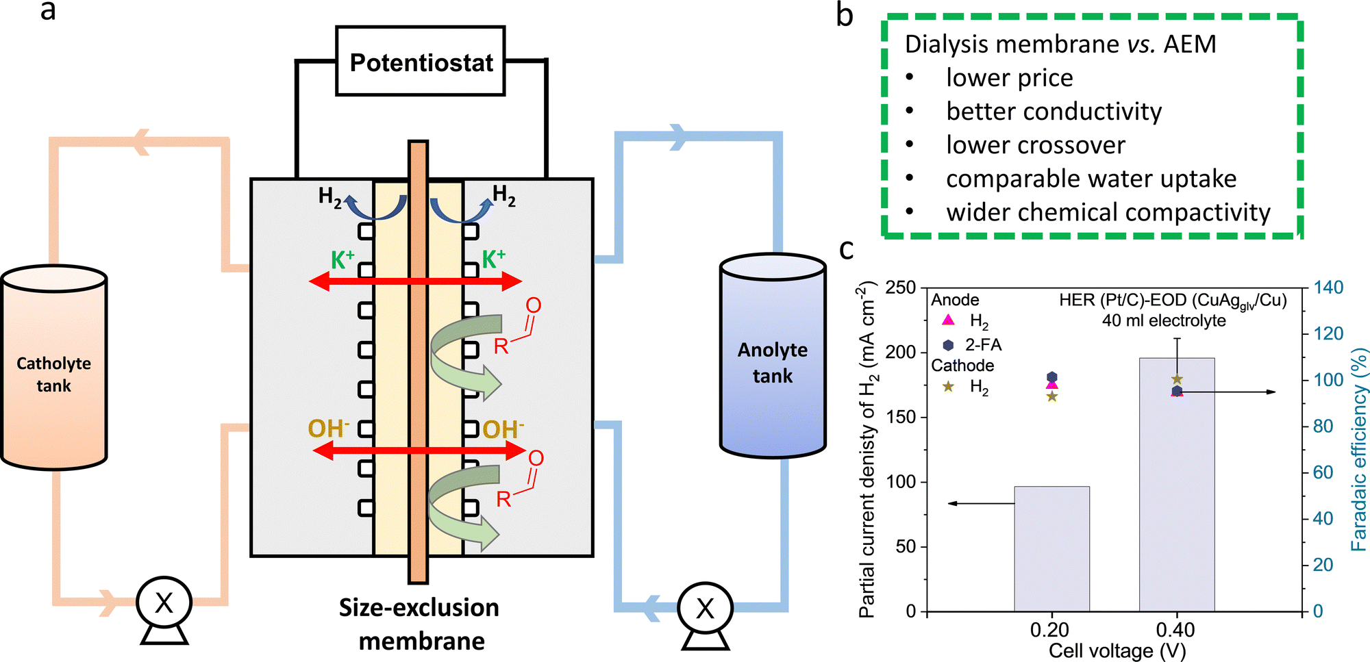 | ||
| Fig. 6 Bipolar H2 production in the system with a dialysis membrane. (a) Scheme of the flow cell with a dialysis membrane. (b) Comparison between the dialysis membrane and AEM. (c) Partial current densities of H2 at different cell voltages with 250 ml of electrolyte. | ||
The crossover of gas and liquid products/reactants was analyzed and compared between the systems with the AEM and dialysis membrane. Benefiting from the similar H2 pressures on both the anode and cathode during their concurrent generation, ∼95% FE of H2 from both electrodes were detected with the minimal gas crossover. For half-hour electrolysis at 0.4 V with the dialysis membrane, the liquid product crossover was quantified from the catholyte (Table S10, ESI†), showing 0.34, 2.02, and 4.19 mM of furfural, 2-FA, and furfuryl alcohol, respectively. In comparison, these values for the AEM-based system are 0, 7.15, and 3.67 mM. The total crossover of liquid reactants and products is <11 mM, corresponding to <4.5% of the initial furfural concentration of 250 mM. While the furfural crossover is insignificant for both systems, the crossover of alcohol (produced from the Cannizzaro reaction) and acid (generated from the EOD reaction) is non-negligible and higher than furfural. The crossover of a negatively charged acid product (i.e., C5H3O3− from EOD reaction) is more considerable through the AEM compared to the dialysis membrane, benefiting from the latter's non-selective characteristics for charged and uncharged species. In fact, the permeability of 2-FA [i.e., 5.56 × 10⁻⁶ cm2 s−1, Fig. S43, ESI†] is one order of magnitude lower than that of the anion selective-AEM [(i.e., 2.80 × 10⁻⁵ cm2 s−1]. In contrast, highly soluble neutral products (i.e., alcohol) are able to crossover through sorption into and subsequent diffusion through the membrane based on the concentration gradient. The slightly higher crossover of furfural alcohol for the dialysis membrane is likely due to its higher water uptake,74 which was determined to be 38% for the dialysis membrane and 26% for the AEM. Such a crossover could be mitigated by optimizing the properties of the dialysis membrane such as reducing the membrane thickness.
Finally, the long-term stability test in the system with the dialysis membrane was performed by conducting 7 successive cycles of 1 hour electrolysis at a cell voltage of 0.4 V (Fig. S45, ESI†). Negligible changes in the current density were observed during the first 1–4 hours, followed by a slight decrease in the performance from the 5th cycle, showing the excellent stability of both the CuAgglv/Cu anode and dialysis membrane.
2.7 Techno-economic analysis (TEA)
To test the economic feasibility of the system considering capital and operation costs, we provided the TEA analysis to quantify the minimum selling price (MSP) of products (details are shown in the supplementary information). The economic performance of the system is analyzed by using the discounted cash flow rate of the return (DCFROR) method developed by the National Renewable Energy Laboratory (NREL).75 We assumed an electrochemical plant capacity of 1500 kg per day H2, based on the hydrogen analysis model developed by the U.S. Department of Energy for producing the same hydrogen quantity via water electrolysis.76We first focused on quantifying the MSP of H2 (Scenario 1), with 2-FA as a byproduct to be sold to the market as the polyethylene 2,5-furandicarboxylate (PEF) precursor, which has been proposed to complement polyethylene terephthalate (PET) as a bio-derived plastic. The separation cost of H2 was only considered (Fig. S46a, ESI†). In the system of AEM with the Pt/C cathode and the CuAgglv/Cu anode at a constant capacitance of H2, the normalized installed capital costs are highly dependent on the current density, which drastically decreased by around 94% to only $2.8 k/kg(H2) when the current density was increased from 25 to 400 mA cm−2 (Fig. S47a, ESI†). The much-decreased capital cost is mainly benefiting from the reduced electrolyzer area and electricity cost. Then, the calculated lowest net MSP of H2 at 400 mA cm−2 with a cell voltage of 0.6 V was $3.2/kg (Fig. 7a), which lies within the range of DOE's target cost of H2 from electrolyzers.76,77 This value is also lower than one of the industrial reported levelized costs of $4.2/kg and $3.7/kg for the proton exchange membrane (PEM) and AEM electrolyzer, respectively.78 It was observed that the furfural costs contributed the most to the net MSP, and meanwhile, the earned revenue is benefited from the co-produced 2-FA from the bipolar H2 production system. In the case of 400 mA cm−2 and 0.6 V, sensitivity analysis (Fig. S47b, ESI†), via varying the factors by ±20%, was performed to determine the key parameters influencing the MSP of H2. The market prices of the reactant furfural and the product 2-FA (sold as PET) are two governing factors, and the separation of H2 showed a negligible contribution.
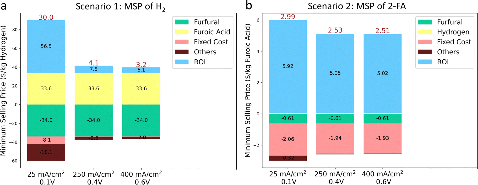 | ||
| Fig. 7 Techno-economic analysis (TEA) for the bipolar H2 production system. (a) Minimum selling price (MSP) of H2 and (b) 2-FA at three different current densities and cell voltages. The electrochemical plant capacity is 1500 kg/day of H2. | ||
We then quantified the economic viability of the plant by calculating the MSP of 2-FA (Scenario 2), with H2 as the byproduct. In this scenario, the separation costs of both H2 and 2-FA are considered (Fig. S46b, ESI†). The installed capital cost (Fig. S48a, ESI†) is the same with Scenario 1, and the different values is owing to the molar mass difference between H2 and 2-FA. The lowest MSP of 2-FA (i.e., $2.51/kg) was obtained from the same condition of 400 mA cm−2 and 0.6 V. Overall, at different voltages and current densities, the estimated MSP ranged between $2.51 and $2.99/kg (Fig. 7b), comparable to its market price between $1 and $99/kg (depend on the purity).79 Different from Scenario 1, the fixed costs and the return on investment (ROI) were the main contributors to expenditure and revenues for the MSP of furoic acid. Moreover, the most sensitive parameters that govern the MSP of 2-FA are the separation cost and the market price of furfural (Fig. S48b, ESI†).
Replacing the cathode catalyst from Pt/C to Ni2P has reduced the catalyst cost by 99%. In addition, the substitution of AEM by the dialysis membrane decreased the electrolyzer cost by 50%. The total installed capital cost and the final MSP in both scenarios did not show significant differences (<5%) by these substitutions, because the major capital cost in an electrochemical plant is the balance of the plant (BOP) cost rather than the electrolyzer stacks (Fig. S49–S51, ESI†). Nevertheless, the development of cheap, stable, and efficient catalysts and membranes are still the major targets in the research community.
3 Conclusions
In summary, being enabled by the favorable thermodynamics and facile kinetics of the EOD reaction, we have achieved bipolar H2 production in the flow cells with cathodic and anodic FEs of ∼100% and current densities of 248 and 390 mA cm−2 at ultra-low cell voltages of 0.4 V and 0.6 V, respectively. These values are higher than most previously reported H2 production rates in the HER–ECO paired systems. Experimental and DFT investigations have elucidated the reaction kinetics of the EOD reaction on Cu electrodes, and its linkage to the Cannizzaro reaction. We further explored a more efficient CuAg bimetallic catalyst synthesized on a porous Cu foam electrode, which demonstrated enhanced kinetics, mass transport, and durability. When the flow electrolyzer was engineered with a cost-effective dialysis membrane as a separator, the excellent cell performance and stability were maintained. Moreover, we linked the EOD reaction with a chemical looping reaction and highlighted the possibility of fundamentally bridged electro- and thermo-catalytic reactions, which could help in rationally designing and predicting novel electrocatalysts and processes. The present work provides a novel, robust approach toward sustainable coproduction of hydrogen and carboxylic acids from bio-derived aldehydes. Supported by the TEA study, the high efficiency, mild operating conditions, and inexpensive cell components of the approach offer potential for its future development toward a cost-effective process at an industrial scale, holding great promises for revolutionizing the renewable pathways toward clean fuels and biomass-based chemical industry.Author contributions
H. L. and W. L. conceived the idea; W. L., M. J., and M. M. W. supervised the project; H. L. performed the electrochemical measurements and materials synthesis; N. A. and M. J. carried out the DFT calculations; Y. C. revised the manuscript and provided the constructive suggestions to this work; J. Y. and W. H. performed the HRTEM characterization; J. L. performed the XRD measurements; A. G. and M. M. W. conducted the TEA analysis. All the authors discussed the results and contributed to the manuscript writing.Conflicts of interest
The authors declare no conflicts of interest.Acknowledgements
This work was supported by the National Science Foundation grant (CBET-1947435) and USDA-NIFA grant (20216702134650). W. Li is grateful to his Herbert L. Stiles Faculty Fellowship, and the IEC competitive fund (20-IEC-019). We thank Drs. Dapeng Jing, Warren E. Straszheim, Carolina Salvati, and Patrick A. Johnston for their assistance with XPS, SEM-EDS, XRD, and ICP-OES measurements. N. Agrawal and M. Janik acknowledge funding from the NSF-CBET 1939464 and computational resources provided by the Extreme Science and Engineering Discovery Environment (XSEDE), which is supported by the National Science Foundation grant number ACI-1053575. N. Agrawal acknowledges the training provided by the Computational Materials Education and Training (CoMET) NSF Research Traineeship (DGE-1449785).References
- J. Turner, G. Sverdrup, M. K. Mann, P. C. Maness, B. Kroposki, M. Ghirardi, R. J. Evans and D. Blake, Int. J. Energy Res., 2008, 32, 379–407 CrossRef CAS.
- R. M. Navarro, M. Pena and J. Fierro, Chem. Rev., 2007, 107, 3952–3991 CrossRef CAS PubMed.
- G. W. Huber, J. Shabaker and J. Dumesic, Science, 2003, 300, 2075–2077 CrossRef CAS PubMed.
- A. Buttler and H. Spliethoff, Renewable Sustainable Energy Rev., 2018, 82, 2440–2454 CrossRef CAS.
- B. You and Y. Sun, Acc. Chem. Res., 2018, 51, 1571–1580 CrossRef CAS PubMed.
- C. C. McCrory, S. Jung, I. M. Ferrer, S. M. Chatman, J. C. Peters and T. F. Jaramillo, J. Am. Chem. Soc., 2015, 137, 4347–4357 CrossRef CAS PubMed.
- B. You, G. Han and Y. Sun, Chem. Commun., 2018, 54, 5943–5955 RSC.
- Q. Feng, X. Z. Yuan, G. Liu, B. Wei, Z. Zhang, H. Li and H. Wang, J. Power Sources, 2017, 366, 33–55 CrossRef CAS.
- J. R. Varcoe, P. Atanassov, D. R. Dekel, A. M. Herring, M. A. Hickner, P. A. Kohl, A. R. Kucernak, W. E. Mustain, K. Nijmeijer and K. Scott, Energy Environ. Sci., 2014, 7, 3135–3191 RSC.
- E. W. Lees, B. A. Mowbray, F. G. Parlane and C. P. Berlinguette, Nat. Rev. Mater., 2021, 1–10 Search PubMed.
- H. Liu and W. Li, Curr. Opin. Electrochem., 2021, 30, 100795 CrossRef CAS.
- G.-F. Chen, Y. Luo, L.-X. Ding and H. Wang, ACS Catal., 2018, 8, 526–530 CrossRef CAS.
- W.-J. Liu, Z. Xu, D. Zhao, X.-Q. Pan, H.-C. Li, X. Hu, Z.-Y. Fan, W.-K. Wang, G.-H. Zhao and S. Jin, Nat. Commun., 2020, 11, 1–11 CrossRef PubMed.
- B. You, X. Liu, X. Liu and Y. Sun, ACS Catal., 2017, 7, 4564–4570 CrossRef CAS.
- B. You, X. Liu, N. Jiang and Y. Sun, J. Am. Chem. Soc., 2016, 138, 13639–13646 CrossRef CAS PubMed.
- Y. Zhang, B. Zhou, Z. Wei, W. Zhou, D. Wang, J. Tian, T. Wang, S. Zhao, J. Liu and L. Tao, Adv. Mater., 2021, 2104791 CrossRef CAS PubMed.
- E. C. Ashby, F. Doctorovich, C. L. Liotta, H. M. Neumann, E. K. Barefield, A. Konda, K. Zhang, J. Hurley and D. D. Siemer, J. Am. Chem. Soc., 1993, 115, 1171–1173 CrossRef CAS.
- S. Kapoor, F. A. Barnabas, M. C. Sauer, D. Meisel and C. D. Jonah, J. Phys. Chem., 1995, 99, 6857–6863 CrossRef CAS.
- S. Zhang, Y. Ma, H. Zhang, X. Zhou, X. Chen and Y. Qu, Angew. Chem., Int. Ed., 2017, 56, 8245–8249 CrossRef CAS PubMed.
- X. Chen, H. Zhang, Z. Xia, S. Zhang and Y. Ma, Catal. Sci. Technol., 2019, 9, 783–788 RSC.
- S. Liang, S. Chen, Z. Guo, Z. Lan, H. Kobayashi, X. Yan and R. Li, Catal. Sci. Technol., 2019, 9, 5292–5300 RSC.
- L. E. Heim, N. E. Schlörer, J.-H. Choi and M. H. Prechtl, Nat. Commun., 2014, 5, 1–8 Search PubMed.
- M. Trincado, V. Sinha, R. E. Rodriguez-Lugo, B. Pribanic, B. de Bruin and H. Grützmacher, Nat. Commun., 2017, 8, 1–11 CrossRef PubMed.
- L. Wang, M. Z. Ertem, R. Kanega, K. Murata, D. J. Szalda, J. T. Muckerman, E. Fujita and Y. Himeda, ACS Catal., 2018, 8, 8600–8605 CrossRef CAS.
- S. Kar, Q.-Q. Zhou, Y. Ben-David and D. Milstein, J. Am. Chem. Soc., 2022, 144(3), 1288–1295 CrossRef CAS PubMed.
- A. S. May and E. J. Biddinger, ACS Catal., 2020, 10, 3212–3221 CrossRef CAS.
- K. Kondo, R. N. Akolkar, D. P. Barkey and M. Yokoi, Copper electrodeposition for nanofabrication of electronics devices, Springer, 2014 Search PubMed.
- S. Ghosh, Thin Solid Films, 2019, 669, 641–658 CrossRef CAS.
- H.-H. Hsu, K.-H. Lin, S.-J. Lin and J.-W. Yeh, J. Electrochem. Soc., 2001, 148, C47 CrossRef CAS.
- S. Nakahara and Y. Okinaka, Acta Metall., 1983, 31, 713–724 CrossRef CAS.
- T. Wang, L. Tao, X. Zhu, C. Chen, W. Chen, S. Du, Y. Zhou, B. Zhou, D. Wang, C. Xie, P. Long, W. Li, Y. Wang, R. Chen, Y. Zou, X.-Z. Fu, Y. Li, X. Duan and S. Wang, Nat. Catal., 2022, 5, 66–73 CrossRef CAS.
- S. Wang, T. Wang, L. Tao, J. Tian, K. Gu, X. Wei, P. Zhou, L. Gan, S. Du and Y. Zou, Angew. Chem., 2021, 134, e202115636 Search PubMed.
- D.-H. Nam, B. J. Taitt and K.-S. Choi, ACS Catal., 2018, 8, 1197–1206 CrossRef CAS.
- A. R. Poerwoprajitno, L. Gloag, J. Watt, S. Cychy, S. Cheong, P. V. Kumar, T. M. Benedetti, C. Deng, K. H. Wu and C. E. Marjo, Angew. Chem., Int. Ed., 2020, 59, 15487–15491 CrossRef CAS PubMed.
- H. G. Cha and K.-S. Choi, Nat. Chem., 2015, 7, 328–333 CrossRef CAS PubMed.
- H. Liu, T.-H. Lee, Y. Chen, E. W. Cochran and W. Li, Green Chem., 2021, 23, 5056–5063 RSC.
- M. A. Bajada, S. Roy, J. Warnan, K. Abdiaziz, A. Wagner, M. M. Roessler and E. Reisner, Angew. Chem., 2020, 132, 15763–15771 CrossRef.
- Y. Y. Birdja and M. T. Koper, J. Am. Chem. Soc., 2017, 139, 2030–2034 CrossRef CAS PubMed.
- J. P. Lange, E. Van Der Heide, J. van Buijtenen and R. Price, ChemSusChem, 2012, 5, 150–166 CrossRef CAS PubMed.
- R. Mariscal, P. Maireles-Torres, M. Ojeda, I. Sádaba and M. L. Granados, Energy Environ. Sci., 2016, 9, 1144–1189 RSC.
- Z. Zhang, E. W. Lees, F. Habibzadeh, D. A. Salvatore, S. Ren, G. L. Simpson, D. G. Wheeler, A. Liu and C. P. Berlinguette, Energy Environ. Sci., 2022, 15, 705–713 RSC.
- Global Plastic Bottles Market-Growth, Analysis, Forecast to (2017–2022). 2016.
- S. B. Scott, T. V. Hogg, A. T. Landers, T. Maagaard, E. Bertheussen, J. C. Lin, R. C. Davis, J. W. Beeman, D. Higgins and W. S. Drisdell, ACS Energy Lett., 2019, 4, 803–804 CrossRef CAS.
- S. H. Lee, J. C. Lin, M. Farmand, A. T. Landers, J. T. Feaster, J. E. Avilés Acosta, J. W. Beeman, Y. Ye, J. Yano and A. Mehta, J. Am. Chem. Soc., 2020, 143, 588–592 CrossRef PubMed.
- J. H. Stenlid, E. C. dos Santos, R. M. Arán-Ais, A. Bagger, A. J. Johansson, B. R. Cuenya, J. Rossmeisl and L. G. M. Pettersson, Electrochim. Acta, 2020, 362, 137111 CrossRef.
- A. M. Román, J. C. Hasse, J. W. Medlin and A. Holewinski, ACS Catal., 2019, 9, 10305–10316 CrossRef.
- M. Neurock, M. Janik and A. Wieckowski, Faraday Discuss., 2009, 140, 363–378 RSC.
- A. M. Román, N. Agrawal, J. C. Hasse, M. J. Janik, J. W. Medlin and A. Holewinski, J. Catal., 2020, 391, 327–335 CrossRef.
- A. J. Bard and L. R. Faulkner, Electrochem. Methods, 2001, 2, 580–632 Search PubMed.
- J. Ryu, D. T. Bregante, W. C. Howland, R. P. Bisbey, C. J. Kaminsky and Y. Surendranath, Nat. Catal., 2021, 4, 742–752 CrossRef CAS.
- L. Zhang, K. Lee and J. Zhang, Electrochim. Acta, 2007, 52, 7964–7971 CrossRef CAS.
- H. Chen, J. Wang, Y. Yao, Z. Zhang, Z. Yang, J. Li, K. Chen, X. Lu, P. Ouyang and J. Fu, ChemElectroChem, 2019, 6, 5797–5801 CrossRef CAS.
- B. Zhou, Y. Zhang, T. Wang, W. Zhou, J. Liu, Y. Zou, L. Tao, Y. Lu and S. Wang, Chem. Catal., 2021, 1, 1493–1504 CrossRef.
- F. Dattila, R. García-Muelas and N. R. López, ACS Energy Lett., 2020, 5, 3176–3184 CrossRef CAS.
- D. Cheng, Z.-J. Zhao, G. Zhang, P. Yang, L. Li, H. Gao, S. Liu, X. Chang, S. Chen and T. Wang, Nat. Commun., 2021, 12, 1–8 CrossRef PubMed.
- H. Liu, J. Park, Y. Chen, Y. Qiu, Y. Cheng, K. Srivastava, S. Gu, B. H. Shanks, L. T. Roling and W. Li, ACS Catal., 2021, 11, 8431–8442 CrossRef CAS.
- J. Lee, H. Liu, Y. Chen and W. Li, ACS Appl. Mater. Interfaces, 2022, 14, 14210–14217 CrossRef CAS PubMed.
- S. Lamaison, D. Wakerley, J. Blanchard, D. Montero, G. Rousse, D. Mercier, P. Marcus, D. Taverna, D. Giaume and V. Mougel, Joule, 2020, 4, 395–406 CrossRef CAS.
- Z. Weng, X. Zhang, Y. Wu, S. Huo, J. Jiang, W. Liu, G. He, Y. Liang and H. Wang, Angew. Chem., 2017, 129, 13315–13319 CrossRef.
- A. Herzog, A. Bergmann, H. S. Jeon, J. Timoshenko, S. Kühl, C. Rettenmaier, M. Lopez Luna, F. T. Haase and B. Roldan Cuenya, Angew. Chem., Int. Ed., 2021, 60, 7426–7435 CrossRef CAS PubMed.
- S. Brittman, A. J. Smith, S. Milenkovic and A. W. Hassel, Electrochim. Acta, 2007, 53, 324–329 CrossRef CAS.
- L. Wang, H. Peng, S. Lamaison, Z. Qi, D. M. Koshy, M. B. Stevens, D. Wakerley, J. A. Z. Zeledón, L. A. King and L. Zhou, Chem. Catal., 2021, 1, 663–680 CrossRef.
- J. Woo, B. C. Moon, U. Lee, H.-S. Oh, K. H. Chae, Y. Jun, B. K. Min and D. K. Lee, ACS Catal., 2022, 12, 4078–4091 CrossRef CAS.
- G. Antczak and G. Ehrlich, Surface diffusion: metals, metal atoms, and clusters, Cambridge University Press, 2010 Search PubMed.
- C. G. Morales-Guio, E. R. Cave, S. A. Nitopi, J. T. Feaster, L. Wang, K. P. Kuhl, A. Jackson, N. C. Johnson, D. N. Abram and T. Hatsukade, Nat. Catal., 2018, 1, 764–771 CrossRef CAS.
- G. Liu, F. Zheng, J. Li, G. Zeng, Y. Ye, D. M. Larson, J. Yano, E. J. Crumlin, J. W. Ager and L.-W. Wang, Nat. Energy, 2021, 1–9 Search PubMed.
- Y. Lin, C. Deng, L. Wu, Y. Zhang, C. Chen, W. Ma and J. Zhao, Energy Environ. Sci., 2020, 13, 2602–2617 RSC.
- M. B. Smith, March's advanced organic chemistry: reactions, mechanisms, and structure, John Wiley & Sons, 2020 Search PubMed.
- H. Liu, T. H. Lee, Y. Chen, E. W. Cochran and W. Li, ChemElectroChem, 2021, 8, 2817–2824 CrossRef CAS.
- E. W. Lees, B. A. Mowbray, F. G. Parlane and C. P. Berlinguette, Nat. Rev. Mater., 2022755–64 Search PubMed.
- Z. Y. Yu, Y. Duan, X. Y. Feng, X. Yu, M. R. Gao and S. H. Yu, Adv. Mater., 2021, 2007100 CrossRef CAS PubMed.
- T. Janoschka, N. Martin, U. Martin, C. Friebe, S. Morgenstern, H. Hiller, M. D. Hager and U. S. Schubert, Nature, 2015, 527, 78–81 CrossRef CAS PubMed.
- Q. Duan, S. Ge and C.-Y. Wang, J. Power Sources, 2013, 243, 773–778 CrossRef CAS.
- D. A. Salvatore, C. M. Gabardo, A. Reyes, C. P. O’Brien, S. Holdcroft, P. Pintauro, B. Bahar, M. Hickner, C. Bae and D. Sinton, Nat. Energy, 2021, 6, 339–348 CrossRef CAS.
- E. C. Tan, M. Talmadge, A. Dutta, J. Hensley, J. Schaidle, M. Biddy, D. Humbird, L. J. Snowden-Swan, J. Ross and D. Sexton, Process Design and Economics for the Conversion of Lignocellulosic Biomass to Hydrocarbons via Indirect Liquefaction. Thermochemical Research Pathway to High-Octane Gasoline Blendstock Through Methanol/Dimethyl Ether Intermediates, National Renewable Energy Lab.(NREL), Golden, CO (United States), 2015.
- B. James, W. Colella, J. Moton, G. Saur and T. Ramsden, PEM electrolysis H2A production case study documentation, National Renewable Energy Lab.(NREL), Golden, CO (United States), 2013.
- G. Saur and C. Ainscough, US Geographic analysis of the cost of hydrogen from electrolysis, National Renewable Energy Lab.(NREL), Golden, CO (United States), 2011.
- W. Paper INNOVATIONS Hydrogen Production Cost by AEM Water Electrolysis [Internet]. 2020. Available from: http://www.ionomr.com.
- Organic Chemical 2-Furoic acid CAS NO. 88-14-2, alibaba.com, accessed 2 October 2021 [Internet]. Available from: https://www.alibaba.com/product-detail/Organic-Chemical-2-Furoic-acid-CAS_60496406282.html?spm=a2700.galleryofferlist.normal_offer.d_title.3ac32bc3qlOShr.
Footnotes |
| † Electronic supplementary information (ESI) available. See DOI: https://doi.org/10.1039/d2ee01427k |
| ‡ These authors contributed equally to this work. |
| This journal is © The Royal Society of Chemistry 2022 |