 Open Access Article
Creative Commons Attribution 3.0 Unported Licence
Anode-less seawater batteries with a Na-ion conducting solid-polymer electrolyte for power to metal and metal to power energy storage†
Yongil
Kim
 ab,
Matthias
Künzel
 ab,
Dominik
Steinle
ab,
Xu
Dong
ab,
Guk-Tae
Kim
*ab,
Alberto
Varzi
*ab and
Stefano
Passerini
ab,
Dominik
Steinle
ab,
Xu
Dong
ab,
Guk-Tae
Kim
*ab,
Alberto
Varzi
*ab and
Stefano
Passerini
 *ab
*ab
aHelmholtz Institute Ulm (HIU), Helmholtzstrasse 11, Ulm 89081, Germany
bKarlsruhe Institute of Technology (KIT) P.O. Box 3640, Karlsruhe, 76021, Germany. E-mail: guk-tae.kim@kit.edu; alberto.varzi@kit.edu; stefano.passerini@kit.edu
First published on 3rd May 2022
Abstract
Seawater batteries (SWBs) have been mostly researched for large scale energy storage and (sub-)marine applications. In a SWB, the aqueous catholyte (seawater) and a non-aqueous anolyte (aprotic solvent solution) are physically separated by a NASICON solid electrolyte membrane. Given the practically unlimited Na+ ion supply from seawater, the energy storage is only limited by the amount of Na stored in the negative electrode. Therefore, the highest volumetric and gravimetric energy densities can be achieved by storing Na metal without the need for a host material. To achieve safe realization of such a cell, a compact, metal-less anode design is herein demonstrated for the first time. The anode compartment integrates the NASICON solid electrolyte, a Na-ion conductive solid-state polymer electrolyte (Na-SPE), having a high ionic conductivity (over 1 mS cm−1 at moderate room temperature), and a negative electrode current collector. The reactive Na metal is not employed in the cell construction, but it is harvested from seawater upon charge (power to metal) and reconverted into energy upon the discharge process (metal to power). The overall round-trip energy efficiency (RTE) of the devices is over 85% at room temperature.
Broader contextLi-ion batteries (LIBs) have been demonstrated to be very successful power sources for a large variety of applications, including portable devices and electric vehicles. However, they are limited in large-scale applications by their cost and scarce availability of raw materials. Similar limitations also affect the deployment of redox flow batteries employing vanadium (VRFBs), leaving the field of large-scale, electrochemical storage systems still not covered by a feasible technology. To address this issue, the Na-seawater cell chemistry, employing the widely available Na as a charge carrier and low-cost seawater as the positive electrode, appears to be very promising. These batteries combine the high voltage of Na with the open positive electrode structure, enabling high energy storage performance. In fact, this cell chemistry is not affected by the capacity limitation of metal ions, taking advantage of the infinite supply of sodium from seawater, but only by the capacity of the negative electrode. Herein, we report a new highly conductive Na-ion conductive solid-state polymer electrolyte combined with NASICON solid electrolyte, for the sodium-seawater battery as a next-generation energy storage system. |
Introduction
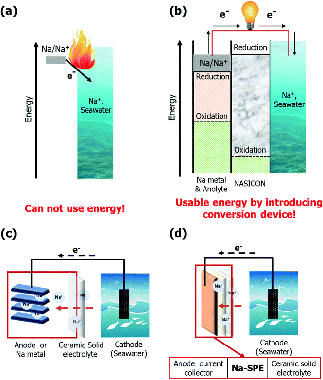
Sodium-seawater batteries (Na-SWBs) are considered as one of the most promising next generation battery chemistries for application in large-scale stationary energy storage systems (ESSs), due to the use of abundant seawater as the cathode.1,2 Interestingly, Na-SWBs can not only be applied as ESS stationary power generation as well as marine and subsea applications, but also have high value-added functions such as desalination, chlorine gas production, and carbon dioxide capture.2–7 Meanwhile, reactive metals are gaining attention as energy carriers suitable for multiple application areas. Reactive metal-based ESSs will be a new alternative to support the clean energy transition, in particular for long-term (seasonal/annual) energy storage.8 Among the reactive metals, sodium is considered as one of the prominent reactive metals due to its properties, such as being an earth abundant metal and providing a sufficiently high energy density.8,9 However, the direct reaction of the Na metal and water results in a spontaneous exothermic reaction releasing much energy (see Fig. 1a). Herein, the Na-SWB enables a smoother (and reversible) conversion of the chemical energy into electricity and vice versa. The energy can be converted and stored as chemical energy through the Na-SWB system (power to metal – Na metal production) and, when required, reconverted, and used as electric energy (metal to power, see Fig. 1b). Reactive metals, on the other hand, may pose compatibility issues with the electrolyte due to their reactivity. Polyether-based solid polymer electrolytes (SPEs), which were pioneered by Wright and Armand,10,11 have been proven to be a reasonable solution for realizing both metal batteries and enhancing safety by avoiding the use of highly volatile and flammable carbonate-based liquid electrolytes.12 Of the many polymer electrolytes studied so far, poly(ethylene oxide) (PEO) is the most studied and is in fact used in commercial batteries.13,14 PEO-based SPEs offer several distinct advantages, mainly in terms of non-volatility, low flammability, no electrolyte leakage, easy processability, high flexibility, and outstanding mechanical robustness.15–21Herein, we propose a new type of highly conductive (over 1 mS cm−1 at 20 °C) Na-ion conductive solid-state polymer electrolyte (Na-SPE) constituted by a mixture of PEO, Na-ion salt, and ionic liquid (IL). This electrolyte is combined with a Na superionic conductor (NASICON) solid electrolyte for the realization of a Na-SWB. To the best of our knowledge, this solvent-free Na-SPE possessing high ionic conductivity is yet to be reported.22 In addition, the ionic conductivity of the Na-SPE is higher than that of Li-ion conductive solid-state polymer electrolytes, even though they share a similar structure, due to the lower ion-pair dissociation energy of Na salts than Li salts.23 As shown in Fig. 1c, a conventional Na-SWB generally operates by reversible storage of Na ions from the unlimited supply of the seawater cathode to the anode host. This means that high energy density can be achieved by applying high-capacity anodes such as Na metal or alloying/conversion materials. However, we propose a metal-less, solid state-based Na-SWB by introducing the Na-SPE as an anolyte without any metallic sodium being initially present in the anodic compartment (see Fig. 1d). The Na-SPE also acts as a soft interlayer between the NASICON solid electrolyte and the anode current collector, self-compensating pore formation when stripping sodium.24 Additionally, since the cell does not involve the sodium metal during manufacturing, it can be assembled safely in a low moisture environment strongly reducing the production costs in terms of safety measures and cost of the highly reactive sodium metal. During the charge process, Na-ions are extracted directly from seawater and stored in the form of electroplated Na metal on the anode current collector (power to metal). The electrochemical processes occurring at the positive and negative electrodes of seawater batteries during charging are 2OH− (aq) → H2O +1/2O2 (g) + 2e− (+NaClO as byproduct) and Na+ + e− → Na, respectively.1,25,26 Conversely, energy is generated during discharge by stripping the Na metal from the anode current collector, when necessary (metal to power). Accordingly, the overall electrochemical processes occurring at the positive and negative electrodes are 2Na+ + H2O +1/2O2 (g) + 2e− → 2NaOH (aq) and Na → Na+ + e−, respectively.1,25,26 The proposed Na-SWB including the Na-SPE displays high round-trip efficiencies under moderate test conditions. Our results demonstrate that Na-SWBs are suitable candidates for next-generation large-scale stationary ESSs and efficient Na metal harvesting systems.8
Results and discussion
Characterization of the Na-SPE
The Na-SPE developed in this study is a cross-linked ternary solid polymer electrolyte composed of a PEO polymer, sodium bis(fluorosulfonyl)imide (NaFSI) salt, and 1-butyl-1-methylpyrrolidinium bis(fluorosulfonyl)imide (Pyr14FSI, ionic liquid) in 10![[thin space (1/6-em)]](https://www.rsc.org/images/entities/char_2009.gif) :
:![[thin space (1/6-em)]](https://www.rsc.org/images/entities/char_2009.gif) 1
1![[thin space (1/6-em)]](https://www.rsc.org/images/entities/char_2009.gif) :
:![[thin space (1/6-em)]](https://www.rsc.org/images/entities/char_2009.gif) 4 molar ratio (10(PEO)-NaFSI-4(Pyr14FSI)). The free-standing, flexible and transparent Na-SPE membrane is demonstrated in Fig. 2a. The ionic conductivity of Na-SPE as a function of temperature is shown in Fig. 2b. It should be noted that at ambient temperature (20 °C) the ionic conductivity of the Na-SPE is about 1.43 mS cm−1, which is, according to our knowledge, the highest value reported so far for Na-ion conducting solid polymer electrolytes (see Fig. 2b and Table S1, ESI†). In addition, it displays sufficiently high ionic conductivity over a wide temperature range from −20 °C to 80 °C, indicating that Na-ions are sufficiently mobile over a typical seawater temperature range. The Na-ion transference number of Na-SPE was also determined as suggested by Bruce and Vincent (see Fig. S1 and Table S2, ESI†).27 Namely, a symmetric Na | Na-SPE | Na cell was characterized by both chronoamperometry (with an applied voltage of 10 mV for 3 hours), and EIS before and after the chronoamperometric step. The resulting Na-ion transference number of Na-SPE at 20 °C is ca. 0.22. Therefore, the practical Na-ion conductivity at 20 °C is around 0.315 mS cm−1, which is quite remarkable for Na-ion conduction at room temperature. With regard to thermal properties, Fig. 2c shows the differential scanning calorimetry (DSC) cooling and heating traces of Na-SPE. The exothermic and the endothermic feature occurring between −90 °C and −73 °C is related to the glass transition. In addition, no clear freezing/melting peaks can be detected, as a result of the IL acting as the plasticizer.28Fig. 2d shows the thermogravimetric analysis (TGA) curve of Na-SPE. No weight loss can be detected below 200 °C in artificial air composed of a mixture of oxygen and nitrogen gas, i.e., indicating that Na-SPE is much more stable than conventional liquid electrolytes. Overall, the thermal properties of the Na-SPE are suitable for the general battery operating conditions.
4 molar ratio (10(PEO)-NaFSI-4(Pyr14FSI)). The free-standing, flexible and transparent Na-SPE membrane is demonstrated in Fig. 2a. The ionic conductivity of Na-SPE as a function of temperature is shown in Fig. 2b. It should be noted that at ambient temperature (20 °C) the ionic conductivity of the Na-SPE is about 1.43 mS cm−1, which is, according to our knowledge, the highest value reported so far for Na-ion conducting solid polymer electrolytes (see Fig. 2b and Table S1, ESI†). In addition, it displays sufficiently high ionic conductivity over a wide temperature range from −20 °C to 80 °C, indicating that Na-ions are sufficiently mobile over a typical seawater temperature range. The Na-ion transference number of Na-SPE was also determined as suggested by Bruce and Vincent (see Fig. S1 and Table S2, ESI†).27 Namely, a symmetric Na | Na-SPE | Na cell was characterized by both chronoamperometry (with an applied voltage of 10 mV for 3 hours), and EIS before and after the chronoamperometric step. The resulting Na-ion transference number of Na-SPE at 20 °C is ca. 0.22. Therefore, the practical Na-ion conductivity at 20 °C is around 0.315 mS cm−1, which is quite remarkable for Na-ion conduction at room temperature. With regard to thermal properties, Fig. 2c shows the differential scanning calorimetry (DSC) cooling and heating traces of Na-SPE. The exothermic and the endothermic feature occurring between −90 °C and −73 °C is related to the glass transition. In addition, no clear freezing/melting peaks can be detected, as a result of the IL acting as the plasticizer.28Fig. 2d shows the thermogravimetric analysis (TGA) curve of Na-SPE. No weight loss can be detected below 200 °C in artificial air composed of a mixture of oxygen and nitrogen gas, i.e., indicating that Na-SPE is much more stable than conventional liquid electrolytes. Overall, the thermal properties of the Na-SPE are suitable for the general battery operating conditions.
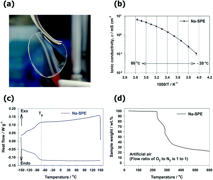 | ||
| Fig. 2 (a) Appearance of the Na-SPE. (b–d) Characterization of the Na-SPE: (b) ionic conductivity; (c) DSC curves; (d) TGA curve. | ||
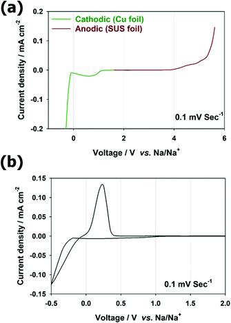
The electrochemical stability of Na-SPE at low potentials is very important for its use as an anolyte in Na-SWBs. Therefore, its electrochemical characterization was performed as in Fig. 3. To determine the electrochemical stability window (ESW) of Na-SPE, two different cells were assembled using copper foil or stainless-steel foil as a working electrode, respectively, for the cathodic and anodic region. Na metal was employed as both counter and reference electrodes (see Fig. 3a). The results of linear sweep voltammetry (LSV) experiments are shown in Fig. 3a. In the anodic sweep, the Na-SPE exhibits stability without significant oxidative decomposition up to 3.9 V vs. Na/Na+, which corresponds to the typical threshold for decomposition of the FSI anions.12,29 During the cathodic sweep, which is most relevant for its use as the anolyte in Na-SWBs, the electrolyte does not exhibit significant current flow prior to the Na metal plating process at approximately −0.04 V vs. Na/Na+, except in the SEI formation process below 1.0 V (almost no decomposition was observed after the 1st cycle in the following reference paper).29 To confirm the behavior of Na metal plating/stripping in anode-less configuration, cyclic voltammetry (CV) was performed as shown in Fig. 3b. Na metal plating/stripping on Cu occurs in the range from −0.5 V to 0.4 V. Also important, from the symmetric Na | Na-SPE | Na cell (Fig. S2, ESI†), the Na symmetric cell has overpotential around 0.22 V at a current density of 0.1 mA cm−2 at room temperature (20 °C), indicating that it can be operated under moderate conditions.
Characterization of the interface between the NASICON solid electrolyte and Na-SPE
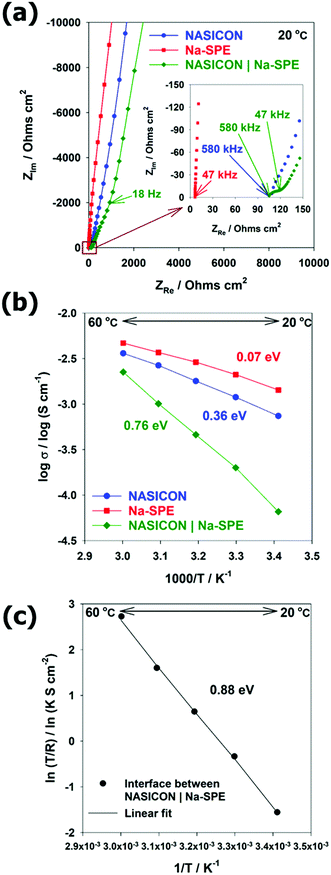
To employ Na-SPE as the anolyte, an efficient Na transport at the interface with NASICON must be ensured. Therefore, the conductivity measurements were performed by EIS at the temperature range from 20 °C to 60 °C by blocking electrode cells with NASICON, Na-SPE, and NASICON | Na-SPE. The resulting Nyquist plots at room temperature (20 °C) and equivalent circuit models are illustrated in Fig. 4a and Fig. S3 (ESI†), respectively. The spectra of NASICON and NASICON | Na-SPE resemble an inclined line at low frequency associated with the almost pure capacitive component, corresponding to the blocking property of the silver electrode against sodium cations.30,31 For the single electrolytes, NASICON and Na-SPE, the intercept of such a line with the real axis corresponds to their ionic resistance (in the case of NASICON the sum of bulk and grain boundary resistances). The Arrhenius plot displaying the ionic conductivity of the different electrolyte systems as a function of the inverse of temperature is reported in Fig. 4b. In all cases, the ionic conductivity increases with increasing temperature. The ionic conductivity of the NASICON | Na-SPE cell is lower than that of the single electrolytes and shows a rather steep increase with temperature. For the NASICON | Na-SPE cell (see Fig. S4a, ESI†), a semicircle can be observed at medium frequency corresponding to the additional interface between the two solid electrolytes.30,32 These differences evidence that the resistance associated with the charge transfer between NASICON and Na-SPE is relatively high.32 The activation energy for Na-ion transfer in the NASICON, Na-SPE, and NASICON | Na-SPE were calculated from the corresponding Arrhenius plots, providing 0.36, 0.07, and 0.76 eV, respectively. For the activation energies of NASICON and NASICON | Na-SPE, the temperature dependence of conductivity fits the linear relationship of the Arrhenius equation (see Fig. S4b, ESI†).33 The activation energy of NASICON was consistent with the reported paper.31 Differently, the Na-SPE shows a concave-like shape that can be better modelled by the empirical Vogel–Tamman–Fulcher relationship, and the activation energy of Na-SPE can be obtained by linear variation (see Fig. S4c, ESI†).33–36 In addition, in order to determine the activation barrier for Na-ion transport at the interface between the two different electrolytes (here, NASICON (solid) | Na-SPE (polymer)), the Arrhenius plot of interfacial resistance was fitted as shown in Fig. 4c. The very good linear fit evidenced the activation energy to be 0.88 eV. In summary, the activation energy barrier for Na-ion transport across the NASICON | Na-SPE interface is the highest among all activation energies. Therefore, with respect to Na-ion transport at solid electrolyte (NASICON) | polymer electrolyte (Na-SPE) interface, desolvation of Na-ions is the rate-determining step due to the strong interaction between sodium cations and polymer.30 Future research should be conducted focusing on the reduction of interfacial resistance.Electrochemical performance of Na-SWB cells using Na-SPE
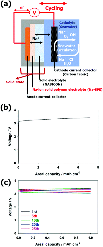
Based on its promising properties, Na-SPE was employed as a solid-state anolyte to realize Na-SWBs as depicted in Fig. S5a (ESI†). The anode and cathode compartments of the SWB cell are physically separated by the NASICON solid electrolyte, and the anode compartment only consists of solid-state materials. While the Na metal serves as the anode active material, the carbon fabric acts as the cathode current collector. In the first discharge step (see Fig. S5b, ESI†), the voltage profile is slightly unstable due to the non-optimal interface between Na metal and Na-SPE during the discharge process. The voltage profile, however, rapidly stabilizes and the cell reversibly operates for over 30 cycles (see Fig. S5c, ESI†). At the 30th cycle, the voltage values at the end of charge and discharge are about 3.38 V and 2.86 V, respectively, corresponding to an energy efficiency at the 30th cycle of ca. 85%.After confirming the compatibility of Na metal with the Na-SPE, metal-free, solid-state anolyte Na-SWBs were assembled and tested. Fig. 5a shows an illustration of the Na-SWB employing the Na-SPE and dendritic Cu foil (d-Cu) as a negative electrode current collector, i.e., without any anode active material. In the pre-charge step, Na metal was plated on the d-Cu foil up to a charge capacity of 7.2 mA h cm−2 (power to metal process as shown in Fig. 5b). After that, the Na-SWB is shown to operate reversibly for over 25 discharge/charge cycles (complete power to metal to power process as shown in Fig. 5c), corresponding to over 600 hours of operation. At the 25th cycle, the voltage values at the end of charge and discharge are about 3.33 V and 3.05 V, respectively, corresponding to a round trip energy efficiency of 94.1%. This value is comparable with that of Li-ion batteries and far higher than most of the metal–air (oxygen) battery systems (including Li, Na, and Zn). Additionally, the Na production using the Na-SWB is much more efficient than employing the most common industrial processes, namely, the Downs and Castner processes.8,37,38 This means that the Na-SWBs can also be used to produce Na for long-term (seasonal/annual) energy storage. The reason for the higher energy efficiency of the metal-free cell (94.1%) compared to the Na metal anode cell (85%) originates from the improved interface between Na-SPE and the Na metal deposited on the dendritic Cu current collector (compare Fig. 5 and Fig. S5, ESI†) due to the absence of a native SEI on such a deposit. Power characteristic measurements were conducted by recording the polarization curve at a scan rate of 0.05 mA s−1 (see Fig. S6, ESI†). The Na-SPE anolyte yields a maximum output power of about 4.9 mW cm−2. Additionally, the higher energy efficiency is caused by the cathode compartment predominantly operating via charge storage at the electric double layer (using the same positive electrode current collector as previously reported, i.e., a hydrophilic activated carbon cloth).39
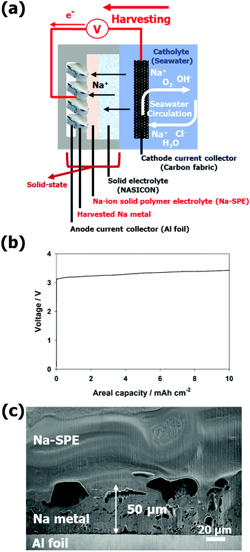
For the Na metal harvesting, the Al current collector can be used as economically advantageous with respect to dendritic Cu (see Fig. 6a). As shown in Fig. 6b, Na metal was plated on the Al current collector up to charge capacity of 10 mA h cm−2 with a terminal charge voltage of about 3.42 V (power to metal process). The plating process was stopped at 10 mA h cm−2, but it is unlimited in theory, the cell was open, and scanning electron microscope (SEM) images were collected on cross-sections obtained by a focused ion beam (FIB). The cross-sectional SEM image clearly shows the harvested Na metal, the Na-SPE, and the Al foil current collector (Fig. 6c). The thickness of the harvested Na metal layer is around 50 μm. Additionally, the EDX mapping image (see Fig. S7, ESI†) allows a distinct differentiation of the interfaces between the Na-SPE, the Na metal, and the Al foil current collector.
Overall, the metal-free Na-SWB employing the Na-ion conductive polymer electrolyte can act as an energy efficient Na metal harvesting system (power to metal) for long-term (seasonal/annual) energy storage and as a secondary battery, providing a highly reversible and energy efficient short-term (from hours to one day) power-to-metal and metal-to-power storage. The future research direction will be to develop and apply a negative electrode current collector with higher reversibility under metal-free anode conditions to further increase reversibility. Although the stability of the cells employing Na-SPE is improved compared to that achieved with liquid electrolytes, their power characteristics are not sufficient for operation under higher current loads. Further work is necessary to reduce the interfacial resistance between Na-SPE and NASICON as well as Na metal.
Conclusions
In this work we propose a new metal-free anode, seawater battery design featuring a Na-ion conducting polymer electrolyte (Na-SPE) as the anolyte. The system has been designed for both energy storage (power to metal to power) and Na metal harvesting (power to metal). The metal-free anode configuration makes the cell construction very easy and cheaper. The energy storage capacity of the reversible cell depends, ultimately, on how much Na metal is harvested from the seawater. This setup can operate reversibly with Na metal capacities of up to 10 mA h cm−2 using dendritic copper or Al current collectors. The polymer electrolyte developed in this work (Na-SPE) displays the highest ionic conductivity at room temperature ever reported to date for a solid polymer electrolyte. Nevertheless, the interfacial resistance between Na-SPE (polymer electrolyte) and NASICON (solid electrolyte) must be reduced to promote charge transport at this heterogeneous interface. These results demonstrate that the proposed seawater battery system is not only applicable in future large-scale stationary energy storage; it is also a viable battery research platform.Experimental
Preparation of the Na-ion conductive solid-state polymer electrolyte (Na-SPE)
The preparation of Na-SPE was carried out in a dry room (dew point < −60 °C) according to the literature.12 All the precursors of Na-SPE were dried as it follows. PEO (Dow Chemical, WSR 301, Mw = 40![[thin space (1/6-em)]](https://www.rsc.org/images/entities/char_2009.gif) 00
00![[thin space (1/6-em)]](https://www.rsc.org/images/entities/char_2009.gif) 000) was pre-dried at 50 °C under vacuum for 24 h with a mechanical pump (10−3–10−4 mbar), followed by further vacuum drying with a turbo molecular pump (10−7–10−8 mbar) for additional 24 h. NaFSI and Pyr14FSI were dried at 70 °C and 90 °C, respectively, under vacuum with a mechanical pump for 24 h and a turbo molecular pump for additional 24 h. As a cross-linking agent, benzophenone (BZP, VWR Chemicals) was dissolved into Pyr14FSI to achieve a BZP/Pyr14FSI ratio of 5 wt% and then stirred for 24 h. PEO and NaFSI powders were first mixed in a glass vial, followed by the addition of BZP/Pyr14FSI solution to achieve the molar ratio of 10 (PEO): 1 (NaFSI): 4 (Pyr14FSI). The paste-like mixture was sealed under vacuum in a small pouch bag and aged at 100 °C overnight. The obtained homogenous material was pressed at 100 °C to achieve a thin polymeric film, which was subsequently cross-linked under a UV light (Cube photo-irradiator, 350 W Hg lamp).
000) was pre-dried at 50 °C under vacuum for 24 h with a mechanical pump (10−3–10−4 mbar), followed by further vacuum drying with a turbo molecular pump (10−7–10−8 mbar) for additional 24 h. NaFSI and Pyr14FSI were dried at 70 °C and 90 °C, respectively, under vacuum with a mechanical pump for 24 h and a turbo molecular pump for additional 24 h. As a cross-linking agent, benzophenone (BZP, VWR Chemicals) was dissolved into Pyr14FSI to achieve a BZP/Pyr14FSI ratio of 5 wt% and then stirred for 24 h. PEO and NaFSI powders were first mixed in a glass vial, followed by the addition of BZP/Pyr14FSI solution to achieve the molar ratio of 10 (PEO): 1 (NaFSI): 4 (Pyr14FSI). The paste-like mixture was sealed under vacuum in a small pouch bag and aged at 100 °C overnight. The obtained homogenous material was pressed at 100 °C to achieve a thin polymeric film, which was subsequently cross-linked under a UV light (Cube photo-irradiator, 350 W Hg lamp).
Analytical characterization
The thermal properties of Na-SPE were evaluated by differential scanning calorimetry (Discovery DSC, TA instruments) and thermogravimetric analysis (Discovery TGA, TA instruments). For the DSC measurement, the Na-SPE (less than 20 mg) was placed in a sealed aluminum pan. The Na-SPE was cooled to −150 °C, followed by heating and cooling cycles between 150 °C and −150 °C at a constant rate of 5 °C min−1. For the TGA measurement, the Na-SPE was also sealed in aluminum pans, whose lid was punched by the instrument immediately before the measurement. Prior to the heating step, the Na-SPE was maintained under isothermal conditions at 30 °C for 30 min. Afterwards, the Na-SPE was heated up from 30 °C to 600 °C at a constant heating rate of 5 °C min−1 in the 1![[thin space (1/6-em)]](https://www.rsc.org/images/entities/char_2009.gif) :
:![[thin space (1/6-em)]](https://www.rsc.org/images/entities/char_2009.gif) 1 vol mixture of N2 and O2 (the flow rate is 20 mL min−1). The harvested Na metal was investigated by SEM (ZEISS Crossbeam XB340 equipped with an EDX detector). To investigate the cross-sectional image of the harvested Na metal, cross-sections of the anode semi-cell stack were obtained using a Capella FIB (gallium ion source) system.
1 vol mixture of N2 and O2 (the flow rate is 20 mL min−1). The harvested Na metal was investigated by SEM (ZEISS Crossbeam XB340 equipped with an EDX detector). To investigate the cross-sectional image of the harvested Na metal, cross-sections of the anode semi-cell stack were obtained using a Capella FIB (gallium ion source) system.
Electrochemical characterization
For measuring ionic conductivity and activation energy, EIS was conducted using an electrochemical interface (Solartron SI 1287, AMETEK) coupled with a frequency response analyzer (Solartron SI 1260, AMETEK) while varying the frequency from 1 MHz to 0.01 Hz with an amplitude of 10 mV. For blocking the electrode configuration, the Ag paste electrode was used for the NASICON solid electrolyte (Na3Zr2Si2PO12, obtained from 4 TO ONE Energy) and the Cu foil electrode was used for the Na-SPE. For measuring the Na-ion transference number, Na | Na-SPE | Na symmetric cells were assembled and subjected to chronoamperometry tests with an applied voltage 10 mV for 3 hours using a potentiostat (VMP Biologic-Science Instruments). For measuring ESW, LSVs were conducted from −0.3 V to 5.6 V at a scan rate of 0.1 mV s−1 (VMP Biologic-Science Instruments). The CV test was performed from −0.5 V to 2.0 V with a scan rate of 0.1 mV s−1 using the following anode-less configuration, Na | Na-SPE | Cu foil (VMP Biologic-Science Instruments). For measuring the overpotential of Na metal plating/stripping in a symmetric cell (Na | Na-SPE | Na), galvanostatic steps with a current density of 0.1 mA cm−2 were applied using a battery tester (Maccor series 4000, U.S.A). Each plating or stripping step lasted for 1 hour. For the seawater battery tests, 0.47 M NaCl (≥99%, VWR Chemicals) solution was used as the catholyte while a carbon fabric (4 × 4 cm) served as the cathode current collector. 2465-Type seawater coin cells and seawater flow cell testers (purchased from 4 TO ONE Energy) were used in connection with a potentiostat (BCS-815, Biologic). The sealable anodic compartments of the seawater coin cells were assembled in a dry room (dew point < −60 °C). As anode current collector commercially available dendritic Cu foil (in the case of anode-less configuration) and Al foil (in the case of Na metal harvesting) were used, respectively.Author contributions
Y. K., G.-T. K., A. V., and S. P. conceived and designed the study. S. P. and A. V. supervised the coordinated experimental investigations. Y. K. performed the experiments based on electrochemical methods and drafted the manuscript. Y. K., G.-T. K., A. V., and S. P. analyzed the results. M. K. performed the FIB/SEM/EDX measurements. D. S. discussed about activation energy. X. D. performed the DSC/TGA measurements. Y. K., G.-T. K., A. V., and S. P. contributed to the writing of the manuscript.Conflicts of interest
There are no conflicts to declare.Acknowledgements
The authors acknowledge the funding of the European Commission under the project STORIES (GAP-101036910) and the financial support by the Helmholtz Association.References
- S. M. Hwang, J.-S. Park, Y. Kim, W. Go, J. Han, Y. Kim and Y. Kim, Adv. Mater., 2019, 31, 1804936 CrossRef PubMed.
- S. T. Senthilkumar, W. Go, J. Han, L. Pham Thi Thuy, K. Kishor, Y. Kim and Y. Kim, J. Mater. Chem. A, 2019, 7, 22803–22825 RSC.
- Y. Kim, A. M. Harzandi, J. Lee, Y. Choi and Y. Kim, Adv. Sustainble Syst., 2021, 5, 2000106 CrossRef CAS.
- Y. Zhang, S. T. Senthilkumar, J. Park, J. Park and Y. Kim, Batteries Supercaps, 2018, 1, 6–10 CrossRef.
- N. Kim, J.-S. Park, A. M. Harzandi, K. Kishor, M. Ligaray, K. H. Cho and Y. Kim, Desalination, 2020, 495, 114666 CrossRef CAS.
- H. Bae, J.-S. Park, S. T. Senthilkumar, S. M. Hwang and Y. Kim, J. Power Sources, 2019, 410-411, 99–105 CrossRef CAS.
- J.-S. Park, S. Kim, Y. Choi, A. M. Harzandi and Y. Kim, ACS ES&T Water, 2021, 1, 2146–2154 Search PubMed.
- M. Baumann, L. Barelli and S. Passerini, Adv. Energy Mater., 2020, 10, 2001002 CrossRef CAS.
- B. Lee, E. Paek, D. Mitlin and S. W. Lee, Chem. Rev., 2019, 119, 5416–5460 CrossRef CAS PubMed.
- M. Armand, J. Chabagno and M. Duclot, Ext. Abs., St. Andrews, Scotland, 1978 Search PubMed.
- P. Vashishta and J. N. Mundy, Fast ion transport in solids: electrodes and electrolytes, Elsevier North Holland, Inc; USA, 1979 Search PubMed.
- Z. Chen, G.-T. Kim, Z. Wang, D. Bresser, B. Qin, D. Geiger, U. Kaiser, X. Wang, Z. X. Shen and S. Passerini, Nano Energy, 2019, 64, 103986 CrossRef CAS.
- J. Kalhoff, G. G. Eshetu, D. Bresser and S. Passerini, ChemSusChem, 2015, 8, 2154–2175 CrossRef CAS PubMed.
- A. Varzi, R. Raccichini, S. Passerini and B. Scrosati, J. Mater. Chem. A, 2016, 4, 17251–17259 RSC.
- J.-H. Shin, W. A. Henderson and S. Passerini, Electrochem. Commun., 2003, 5, 1016–1020 CrossRef CAS.
- J.-H. Shin, W. A. Henderson, C. Tizzani, S. Passerini, S.-S. Jeong and K.-W. Kim, J. Electrochem. Soc., 2006, 153, A1649 CrossRef CAS.
- G.-T. Kim, G. B. Appetecchi, F. Alessandrini and S. Passerini, J. Power Sources, 2007, 171, 861–869 CrossRef CAS.
- G. T. Kim, G. B. Appetecchi, M. Carewska, M. Joost, A. Balducci, M. Winter and S. Passerini, J. Power Sources, 2010, 195, 6130–6137 CrossRef CAS.
- M. Joost, M. Kunze, S. Jeong, M. Schönhoff, M. Winter and S. Passerini, Electrochim. Acta, 2012, 86, 330–338 CrossRef CAS.
- M. Wetjen, G.-T. Kim, M. Joost, M. Winter and S. Passerini, Electrochim. Acta, 2013, 87, 779–787 CrossRef CAS.
- M. Joost, G. T. Kim, M. Winter and S. Passerini, Electrochim. Acta, 2013, 113, 181–185 CrossRef CAS.
- L. Qiao, X. Judez, T. Rojo, M. Armand and H. Zhang, J. Electrochem. Soc., 2020, 167, 070534 CrossRef CAS.
- E. Jónsson and P. Johansson, Phys. Chem. Chem. Phys., 2012, 14, 10774–10779 RSC.
- T. Fuchs, B. Mogwitz, S.-K. Otto, S. Passerini, F. H. Richter and J. Janek, Batteries Supercaps, 2021, 4, 1145–1155 CrossRef CAS.
- Y. Kim, J. Jung, H. Yu, G.-T. Kim, D. Jeong, D. Bresser, S. J. Kang, Y. Kim and S. Passerini, Adv. Funct. Mater., 2020, 30, 2001249 CrossRef CAS.
- Y. Kim, A. Varzi, A. Mariani, G.-T. Kim, Y. Kim and S. Passerini, Adv. Energy Mater., 2021, 11, 2102061 CrossRef CAS.
- P. G. Bruce and C. A. Vincent, J. Electroanal. Chem. Interfacial Electrochem., 1987, 225, 1–17 CrossRef CAS.
- M. Moreno, E. Simonetti, G. B. Appetecchi, M. Carewska, M. Montanino, G. T. Kim, N. Loeffler and S. Passerini, J. Electrochem. Soc., 2016, 164, A6026–A6031 CrossRef.
- Y. Kim, G.-T. Kim, S. Jeong, X. Dou, C. Geng, Y. Kim and S. Passerini, Energy Storage Mater., 2019, 16, 56–64 CrossRef.
- Y. Uchida, G. Hasegawa, K. Shima, M. Inada, N. Enomoto, H. Akamatsu and K. Hayashi, ACS Appl. Energy Mater., 2019, 2, 2913–2920 CrossRef CAS.
- B. P. Dubey, A. Vinodhkumar, A. Sahoo, V. Thangadurai and Y. Sharma, ACS Appl. Energy Mater., 2021, 4, 5475–5485 CrossRef CAS.
- F. Sagane, T. Abe, Y. Iriyama and Z. Ogumi, J. Power Sources, 2005, 146, 749–752 CrossRef CAS.
- J. F. Ihlefeld, P. G. Clem, B. L. Doyle, P. G. Kotula, K. R. Fenton and C. A. Apblett, Adv. Mater., 2011, 23, 5663–5667 CrossRef CAS PubMed.
- R. K. Gupta and H.-W. Rhee, Electrochim. Acta, 2012, 76, 159–164 CrossRef CAS.
- J. Zhang, H. Wen, L. Yue, J. Chai, J. Ma, P. Hu, G. Ding, Q. Wang, Z. Liu, G. Cui and L. Chen, Small, 2017, 13, 1601530 CrossRef PubMed.
- G. Chen, Y. Bai, Y. Gao, Z. Wang, K. Zhang, Q. Ni, F. Wu, H. Xu and C. Wu, ACS Appl. Mater. Interfaces, 2019, 11, 43252–43260 CrossRef CAS PubMed.
- J. W. Choi and D. Aurbach, Nat. Rev. Mater., 2016, 1, 16013 CrossRef CAS.
- Z. Khan, M. Vagin and X. Crispin, Adv. Sci., 2020, 7, 1902866 CrossRef CAS PubMed.
- J. Park, J.-S. Park, S. T. Senthilkumar and Y. Kim, J. Power Sources, 2020, 450, 227600 CrossRef CAS.
Footnote |
| † Electronic supplementary information (ESI) available. See DOI: https://doi.org/10.1039/d2ee00609j |
| This journal is © The Royal Society of Chemistry 2022 |

