
 Open Access Article
 This Open Access Article is licensed under a
 Creative Commons Attribution 3.0 Unported Licence
Direct air capture: process technology, techno-economic and socio-political challenges
María
Erans
 a,
Eloy S.
Sanz-Pérez
a,
Dawid P.
Hanak
b,
Zeynep
Clulow
c,
David M.
Reiner
c and
Greg A.
Mutch†
*de
a,
Eloy S.
Sanz-Pérez
a,
Dawid P.
Hanak
b,
Zeynep
Clulow
c,
David M.
Reiner
c and
Greg A.
Mutch†
*de
aDepartment of Energy, Chemical, and Mechanical Technology, ESCET, Universidad Rey Juan Carlos, C/Tulipán s/n, 28933 Móstoles, Madrid, Spain
bEnergy and Power Theme, School of Water, Energy and Environment, Cranfield University, Bedford, Bedfordshire MK43 0AL, UK
cEnergy Policy Research Group, Judge Business School, University of Cambridge, Trumpington Street, Cambridge, CB2 1AG, UK
dMaterials, Concepts and Reaction Engineering (MatCoRE) Research Group, School of Engineering, Newcastle University, Newcastle-upon-Tyne, NE1 7RU, UK
eCentre for Energy, Newcastle University, Newcastle-upon-Tyne, NE1 7RU, UK. E-mail: greg.mutch@newcastle.ac.uk
First published on 28th February 2022
Abstract
Climate change mitigation scenarios that meet the Paris Agreement's objective of limiting global warming usually assume an important role for carbon dioxide removal and negative emissions technologies. Direct air capture (DAC) is a carbon dioxide removal technology which separates CO2 directly from the air using an engineered system. DAC can therefore be used alongside other negative emissions technologies, in principle, to mitigate CO2 emissions from a wide variety of sources, including those that are mobile and dispersed. The ultimate fate of the CO2, whether it is stored, reused, or utilised, along with choices related to the energy and materials inputs for a DAC process, dictates whether or not the overall process results in negative emissions. In recent years, DAC has undergone significant technical development, with commercial entities now operating in the market and prospects for significant upscale. Here we review the state-of-the-art to provide clear research challenges across the process technology, techno-economic and socio-political domains.
 María Erans | María Erans obtained a PhD degree in Energy & Power from Cranfield University in 2017. She is currently a Marie Skłodowska-Curie COFUND postdoctoral fellow at Universidad Rey Juan Carlos. Her research mainly focuses on the development and testing of solid adsorbents/sorbents for CO2 capture, particularly materials for calcium looping, chemical looping combustion and direct air capture. She has also focused on the scalability of fluidised-bed reactors for CO2 capture processes and microwave technologies. Her research activity is highly inter-disciplinary lying between the areas of chemistry and engineering. |
 Eloy S. Sanz-Pérez | Eloy S. Sanz-Pérez obtained his MS and PhD degrees in Chemical Engineering from Rey Juan Carlos University (Spain). He has been visiting researcher and post-doc at the University of Nottingham (UK) and the Georgia Institute of Technology (US). Dr Sanz-Pérez is currently Associate Professor at Rey Juan Carlos University and his research interests include CO2 capture and solar energy storage. He has received several recognitions for his research work, including the Nicklin Medal (Institution of Chemical Engineers, IChemE) and the EFCE Excellence Award in Fluid Separations (European Federation of Chemical Engineering, EFCE). |
 Dawid P. Hanak | Dawid P. Hanak holds a Master of Science (MSc) in Carbon Capture and Transport, an Executive Master in Business Administration (MBA) and a PhD in Energy from Cranfield University. He is currently a Senior Lecturer in Energy and Process Engineering at Cranfield University. He leads a research group in process engineering for sustainable development that aims to develop breakthrough process designs for direct air capture, carbon capture, hydrogen production, and high-value chemicals and fuels synthesis. He has extensive expertise in process design and development, third-party validation, techno-economic feasibility assessment, environmental impact assessment, and business model development. |
 Zeynep Clulow | Zeynep Clulow is a Research Associate at the Energy Policy Research Group at Judge Business School, University of Cambridge. Her current research interests are public attitudes towards energy technologies and the political economy of negative emission technologies, particularly across the global North and South. Prior to joining Cambridge, she completed an Economic and Social Research Council-funded PhD that investigated the role of instrumentalist factors and worldviews in shaping CO2 emissions trends at Nottingham University, served as a Research Fellow in the Department of Politics at Warwick University and taught international theory and quantitative methods at Aston University. |
 David M. Reiner | David M. Reiner, PhD is Associate Professor of Technology Policy at Judge Business School, University of Cambridge. He is also Assistant Director of the Energy Policy Research Group at Cambridge University, Deputy Director (Systems & Policy) of the UK CCS Research Centre and serves on the CCUS Council, which is chaired by the UK Energy Minister. He currently is co-I on several UK and European grants on carbon capture and greenhouse gas removal. His research focuses on energy and climate change policy, economics, regulation, and public attitudes, with a focus on social license to operate. |
 Greg A. Mutch | Greg A. Mutch holds a Master of Chemistry (MChem) and a PhD in Chemical Engineering from the University of Aberdeen. He is currently a Royal Academy of Engineering Research Fellow at Newcastle University, and co-investigator in a ∼£9M Programme Grant on high-selectivity membrane separations from the UK's Engineering & Physical Sciences Research Council. He sits on the Steering Group of the BEIS CCUS Early Career Professional's Forum and is an Academic Member of UKCCSRC. His research interests are in sorbents and membranes for chemical separation processes, particularly CO2 capture, as well as materials characterization from the molecular to device scale. |
Broader contextDirect air capture (DAC) is an engineered process for removing CO2 directly from the air. It is technically challenging as CO2 is present at ∼0.04% in the air. This is some 2–3 orders of magnitude lower in concentration than other commonly targeted sources for capturing CO2, such as flue gases resulting from energy generation and industrial processes. Nonetheless, DAC has received an increasing amount of attention due largely to development and deployment by a limited number of start-ups. There is also a growing body of research on new materials and processes for DAC, and a need to understand the financial costs and environmental impacts associated with DAC. Moreover, there are emerging questions related to public acceptance, policy requirements, and integration of DAC in the energy system, particularly as related to the energy transition and climate change mitigation. This review article seeks to broadly appraise and interrogate these themes to highlight emerging research challenges across the scientific, engineering, economic, and socio-political domains. |
1 Introduction
Climate change is the biggest challenge humanity has ever faced. This is due to its effects being both profound and global. Human activities are unequivocally responsible for an increase in atmospheric concentrations of greenhouse gases (GHGs) since the Industrial Revolution (ca. 1750).1 The concentration of carbon dioxide (CO2), the primary GHG responsible for driving climate change, increased from a pre-industrial value of 280 ppm to 412 ppm in 2020, the highest value in at least 2 million years.2Observed global temperature is increasingly higher than that simulated accounting for natural factors alone, with human activity explaining all the deviation (Fig. 1). As a result, mean global surface temperature has increased by 1.07 °C to date and each of the last four decades has been successively warmer than any previous decade since 1850.3 Global temperature increase has already caused widespread retreat of glaciers and Arctic ice, a sea level increase of ∼0.2 m, as well as more frequent and intense heavy precipitation events and hot extremes.1 All additional warming makes abrupt and irreversible changes in the climate system more likely. These are usually referred to as tipping points.4
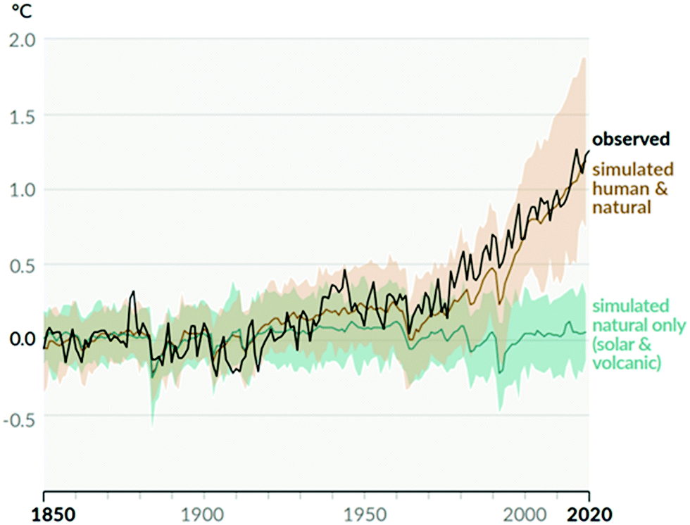 | ||
| Fig. 1 Change in global surface temperature (annual average) as observed and simulated using human and natural, and only natural factors (both 1850–2020). Taken from Fig. SPM.1 b in ref. 1. | ||
Unless the global economy is rapidly decarbonised, i.e., GHG emissions are halved in the next decade and net-zero is achieved by ca. 2050, global mean temperature will increase by at least 2 °C by 2050 compared to the 1850–1900 average. This is projected to result in 1.7 times more frequent heavy precipitation events, 2.4 times more frequent droughts and 13.9 times more frequent hot temperature extremes.1 Moreover, projected sea level rise will result in the flooding of land used by 100 million people worldwide,5 and 30–140 million people of the Global South becoming climate refugees.6
1.1. Strategies for reducing CO2 emissions
To avoid the worst outcomes of an exacerbated climate change, the Paris Agreement was signed in 2015 with the aim of “holding the increase in the global average temperature to well below 2 °C above pre-industrial levels and pursuing efforts to limit the temperature increase to 1.5 °C”. With that aim, net emissions of GHGs should halve over the next decade and become net-zero by 2050. Considering that current annual emissions are over 35 billion tCO2e,7 the magnitude of the task becomes evident. Current pledges announced by all countries towards decarbonization would only result in a fall in CO2 emissions of 40% by 2050.8 At the time of writing, the most recent UN Climate Change Conference of Parties (COP26) seeks to improve upon these.To tackle GHG emissions, all sectors must be scrutinized, however, energy-related applications are responsible for over two thirds of total emissions.9 These are mostly allocated to industry, transport and buildings. Thus, most efforts to curb emissions are aimed at decreasing energy consumption, electrification of the energy system, and decarbonizing electricity generation.
![[thin space (1/6-em)]](https://www.rsc.org/images/entities/char_2009.gif) 10,11 8%,8,12 and 23% are deemed possible.§13 Although the smaller reductions may seem negligible, they represent global change after 30 years, including a development of all regions, especially those whose current energy use is insufficient and needs to be increased. On the other hand, ‘business as usual’ scenarios in the same reports project higher energy consumption than today. Degrowth scenarios go further and directly propose reductions in Gross Domestic Product (GDP) trajectories, including sharper reductions in final energy consumption, and ultimately finding a non-economic variable to express quality of life. High energy-GDP decoupling and lower final energy consumption require a slower expansion of renewable energy and deployment of fewer negative emission technologies (NETs). These models claim a lower risk for socio-technical feasibility, but entail a higher risk for socio-political feasibility.14
10,11 8%,8,12 and 23% are deemed possible.§13 Although the smaller reductions may seem negligible, they represent global change after 30 years, including a development of all regions, especially those whose current energy use is insufficient and needs to be increased. On the other hand, ‘business as usual’ scenarios in the same reports project higher energy consumption than today. Degrowth scenarios go further and directly propose reductions in Gross Domestic Product (GDP) trajectories, including sharper reductions in final energy consumption, and ultimately finding a non-economic variable to express quality of life. High energy-GDP decoupling and lower final energy consumption require a slower expansion of renewable energy and deployment of fewer negative emission technologies (NETs). These models claim a lower risk for socio-technical feasibility, but entail a higher risk for socio-political feasibility.14
During the 1970's and 1980's, the share of nuclear in global energy consumption went from 0 to 6.6% in a few decades and hundreds more nuclear reactors were projected worldwide. However, the trend stopped abruptly and the share of nuclear has declined steadily, reaching 4.3% in 2020.17 Even though alternative coolants, passive cooling, and fast-spectrum and small modular reactors offer improvements over current technology, the future role of nuclear fission in net-zero models is unclear – some studies anticipate significant increases in operating capacity while some others project continued decline.8,10–13 Apart from social acceptance and proliferation concerns, nuclear power faces two major challenges: the significant time between decision and commissioning of new plants (∼10–20 years),11 and the high cost of the obtained electricity (3–4 times more expensive than solar and wind energy).15 Even though nuclear power can provide baseload supply, the drawbacks above make a quick and cheap energy transition difficult, eroding the interest of most countries in this technology, which has even been referred to as “the non-solution solution”.18
According to the Intergovernmental Panel on Climate Change (IPCC), carbon capture and storage (CCS) processes are necessary to achieve the Paris Agreement goals at lowest cost; a lack of scalable CCS technologies by the end of the century would entail an increase of 29–297% (mean value 138%) in total mitigation costs compared to default technology assumptions (scenarios without CCS but with other low-carbon technologies) to limit the atmospheric CO2 concentration at 450 ppm (currently the atmospheric concentration is ∼419 ppm).¶11 This increase is significantly higher than that corresponding to any other scenario with a limited availability of technologies (e.g., reduced renewable energy penetration).
CCS technologies are proposed to reduce the rate of release of CO2 from large, stationary sources by capturing a large portion of CO2 from gas mixtures destined for the atmosphere, with subsequent storage of CO2 in geological sites. Thus, they may find application in sectors where CO2 emissions cannot be avoided as they are inherent to the process, e.g., steel and cement production, and the production of various chemicals, as well as from any remaining fossil-fuel power generation. Carbon dioxide removal (CDR) technologies seek to go further, removing CO2 already present in the air. If a specific CDR technology results in net-negative CO2 emissions, e.g., it is powered by renewable energy and the captured CO2 is stored, then it may be called a NET. Among various NETs, two of them stand out as variations of CCS: bioenergy with carbon capture and storage (BECCS) and direct air carbon capture and storage (DACCS).
1.2. Contribution and structure of the review
This review article focusses on the upstream aspect of DACCS, i.e., direct air capture (DAC). To date, DAC has largely been developed by a small number of start-ups. Thus, past reviews of DAC have focused on materials used in those processes. Instead, here we seek to take a holistic view of DAC to identify research challenges across multiple length and time scales, and therefore disciplines. First, in Section 2, we briefly discuss the advantages and limitations of some photosynthesis-based NETs, to set a context for DAC in terms of costs, energy requirements and interaction with Earth systems. In this section we also consider DAC at a high level, i.e., the potential role of DAC in climate change mitigation, and in CO2 reuse and utilisation. In Section 3, we appraise the most developed DAC processes to identify the research challenges that have emerged during deployment, and how new materials could be used to address these, or to develop modified processes. Uniquely, we also identify entirely new approaches to DAC that are beginning to appear in the literature, e.g., those relying on electrochemical devices. In Section 4 we assess the cost and sustainability of DAC in detail, reviewing recent work on techno-economic analysis (TEA) and life-cycle analysis (LCA). In Section 5, for the first time, we identify the socio-political challenges that will require consideration if DAC develops as a component of the energy system and climate change mitigation efforts. Finally, we provide concise, high-level research challenges that the science, engineering, economics, and socio-political communities must tackle in the coming years to develop more efficient, sustainable, and societally acceptable DAC technologies.2 Negative emissions technologies and direct air capture
2.1. Background on negative emissions technologies
It has been widely suggested that NETs will be necessary to reach climate targets, especially the 1.5 °C goal set by the Paris Agreement.19–24 In spite of this and the increasing need for NETs, current knowledge is incomplete,25,26 but is however developing at a fast pace.23,24 The last IPCC report, AR5, stressed the importance of NETs in order to achieve the 2 °C scenario also; however, it highlighted the uncertainties regarding the availability, scale and possible negative impacts of NETs.27 Only two NETs have been incorporated into the most recent assessment by the IPCC; BECCS, and afforestation and reforestation (AR).28 There may be more NETs included in the analysis used for their new assessment report, AR6, which is due to be released in 2022. It is, however, always important to note that NETs are complementary technologies to conventional decarbonisation and climate change mitigation options, not a substitute.29NETs have been described as, “the intentional human efforts to remove CO2 emissions from the atmosphere”.24,30,31 A wide variety of NETs have been proposed in literature; some of these technologies are well investigated such as AR, and soil carbon sequestration (SCS), while others are in earlier stages of development.31,32 NETs can be categorised according to different variables such as technology category, implementation options, their interaction with earth systems, and CO2 storage medium (Fig. 2). Five of the seven technology categories in Fig. 2 (AR, SCS, biochar (BC), BECCS, and ocean fertilisation (OF)) use photosynthesis to capture CO2 from the air, while DAC, ocean alkalinisation (OA) and enhanced weathering (EW) chemically bind CO2 to synthetic or natural materials, respectively. Other technological divisions can be made, such as whether the technology is land or ocean based, domestic or transboundary, and based on the selected storage medium.24
 | ||
| Fig. 2 NET pathways. Taken from Negative emissions – part 1: research landscape and synthesis, ref. 24, licensed under CC BY 3.0. | ||
Key advantages of SCS include that it can be applied without changing land use, and that the practices involved are well understood and can be deployed immediately. Additionally, the water footprint of SCS has been deemed to be relatively minor.54 The main disadvantage of SCS is sink saturation, i.e., a limited amount of carbon can be stored in soil even with the use of SCS technologies.55 The initial carbon capture rate is high but it decreases with time to zero, when a new equilibrium is reached.56,57 The saturation period varies from decades to centuries depending on the technology and soil temperature etc., but the standard saturation period is considered to be ∼20 years.54 Moreover, if the carbon is to remain in the soil these practices need to be maintained after the soil has reached saturation, with an associated cost, otherwise the CO2 will be released to the atmosphere.56,58 Finally, the potential storage capacity of SCS varies significantly, depending on where it is applied. Thus, more studies are required to compare and unify criteria, and to address the scarcity of cost estimates (of the few in the literature, ∼20–100 $ per tCO2 for ∼1.4–3.7 GtCO2 per year).30
One of the main challenges for assessing BC use is the lack of field studies; the efficacy of BC is extremely site dependent as soil varies with location, climate, etc. Therefore, comprehensive studies on feasibility, CO2 storage capacity and timescale, soil type, BC materials, and potential side effects are urgently required. Recently, field studies looking at CO2 emissions on BC treated fields are emerging, showing the potential use of this technology in different areas.68–71 Another key point that should be carefully considered is the realistic availability of biomass for BC production, as it will have to compete with biomass conversion and combustion for energy production. The estimated capture potential of using BC ranges from 0.6–11.9 GtCO2 per year depending on biomass availability.72–74 The projected cost of this technology ranges from 60–120 $ per tCO2, with higher prices for dedicated feedstocks which points towards using waste materials where possible.54,75,76
The main limiting factors for the large-scale deployment of BECCS are land, biomass and storage availability.26,78,81 Side effects of BECCS include the emissions derived from land use change, such as those produced from deforestation, and land use change induced by economic markets. Additionally, as with other NETs, the albedo effects of cultivating biomass for BECCS should be considered. For example, at higher altitudes, biomass cultivation can lead to a reduction in the area of reflective snow surfaces.82 Land competition should be carefully investigated as well, as BECCS could have an impact on biodiversity, water use, and nutrient availability/distribution.80,83–86 Mass deployment of BECCS may also pose a threat to food security and potentially lead to higher food prices.87,88 Recently, integrating BECCS with algae-based processes has been proposed, which will be discussed further below. This biomass alternative has a high photosynthetic efficiency and high yields,89 and it may also help in reducing land competition.90
Even with the challenges presented, BECCS still has significant potential to contribute to the energy transition, with an estimated energy production in 2050 of 60–1548 EJ per year.91–94 The estimated cost of BECCS ranges from 15–400 $ per tCO2.95–97 Note that the issues around BECCS described here are complex, and inter-dependent, and have thus been the subject of more detailed discussion than is suitable here.98–101
2.2. The potential role of direct air capture in climate change mitigation
The use of DAC for climate change mitigation was first introduced by Lackner in the 1990's.105 In the following years many studies and comments aimed to assess the practical relevance of DAC in reducing atmospheric CO2 levels.106–115 Experimental works were published too, but their number only increased significantly a decade or so after the concept of DAC was introduced.DACCS is often compared with CCS due to their similarity. While the goal of CCS is to reduce the rate of CO2 emissions from a specific process (or group of processes), DACCS targets the removal of CO2 that is already in the atmosphere. Thus, CCS technologies are typically proposed for large, stationary sources of CO2, but not for distributed and mobile sources. However, as distributed sources account for approximately half of global CO2 emissions, DACCS is increasingly proposed as a NET. Thus, DACCS and CCS technologies should be considered as complementary, with DAC offering some unique potential advantages. For example, DAC facilities process air, which typically has lower amounts of contaminants present in flue gases (SO2, NOx, etc.) that usually reduce the performance and life span of CO2 sorbents. Moreover, DAC is not limited to locations with large, stationary CO2 sources; in principle, it can be applied anywhere (however, ideally this would be in proximity with both an energy source and CO2 storage site). This can potentially lead to multiple advantages: existing industries that operate on a relatively small scale do not need to modify their processes; CO2 producing facilities that are geographically remote do not require extensive CO2 transport infrastructure; DAC facilities can be co-located with renewable energy generation facilities to reduce transmission losses, and/or with CO2 storage facilities to minimise transport costs and infrastructure.
Despite the potential advantages of DAC, there are also uncertainties. For example, as with CCS, the environmental risks and uncertainties associated with CO2 storage (cost, long-term monitoring, induced seismicity, and leakage) should be addressed,116 as well as specific DAC-related concerns on the financial, energy and materials requirements, as well as socio-political acceptance. All these topics are discussed in detail in later sections of this review.
2.3. Direct air capture and CO2 use/utilisation
Although geological storage of CO2 should be the primary aim for climate change mitigation strategies (i.e., DACCS), CO2 captured from the air can also be used directly or utilised as a feedstock in the production of valuable products such as chemicals or fuels. The use or utilisation of CO2 in this way can lower the net costs of DAC technologies and recycle a useful material that otherwise would be stored in deep reservoirs.117 A number of routes can be followed to use or utilise CO2,118–120 with a selection of these introduced to provide context for later discussions.Syngas, a mixture of H2 and CO, is an intermediate used in the production of synthetic ammonia and methanol, among other compounds. Steam reforming of fossil gas is currently the most widespread route to obtain syngas. This process emits CO2 to the atmosphere. CO2 reforming (also known as dry reforming) is an alternative method of producing syngas by reacting CO2 and methane.125 Dry reforming requires high temperatures (900–1200 K) and the deposition of soot deactivates the catalyst, so it is not yet widely utilised.126
Methanol is an important building block in the synthesis of olefins, dimethyl ether, and fuels, and is thus capable of displacing fossil fuels.127,128 Besides, methanol can be used as an energy carrier. As a liquid, it can be handled and transported more easily than gases or solids.129 Methanol is currently produced from syngas that, in turn, is obtained from fossil fuels. However, it can also be produced from CO2 in one of the simplest processes available to convert CO2 into liquid products.127 Electrochemical reduction,130–132 and catalytic hydrogenation,133,134 processes can be used. Large plants show more potential, with facilities producing as much as 50000 tMeOH and using 71600 tCO2 per year suggested as being feasible.134
Methane is currently used to produce electricity, heat, and chemicals. Methane is primarily obtained from natural gas, and is referred to as substitute natural gas (SNG) when obtained sustainably.135 SNG has a high purity and can be injected directly into the natural gas grid. As above with methanol, methane can be synthesised by two main paths: electrochemical reduction,136–138 and catalytic hydrogenation (methanation),139,140 of CO2.
Gasoline, diesel, and kerosene are classically obtained via the Fischer–Tropsch process using H2 and CO to obtain alkanes, which are subsequently upgraded.141 Alternatively, clean methanol can be transformed into fuels by means of industrial processes such as olefin synthesis, oligomerization, and hydrotreating,141 or dimethyl ether can be transformed into high-octane gasoline.142
New engineered concepts using algae are emerging. First, ABECCS (algae and bioenergy with CCS) has been proposed, where land biomass is used in a combustion process to produce electricity, and a portion of the captured CO2 is used for algae cultivation, whilst the rest can be stored.90 Second, microbial carbon capture cells (MCCs) have also been investigated for mitigating CO2 emissions, where the off gas is transferred to an algal cathode chamber, which leads to waste water treatment, algal growth and electricity generation by a voltage shift without energy input.150,151
3 Direct air capture process technology; state of the art and opportunities
3.1. Chemical separation processes and application to CO2 separation
The production of key global resources such as chemicals, fuels, foods, and medicines routinely involves separation processes. These may be based upon distillation, drying, evaporation, extraction, sorption, membranes and crystallisation (presented in approximate descending order of energy-intensity and from thermal to non-thermal processes).152 Due to the ubiquity of separation processes and the extensive use of energy-intensive, thermal separation processes, separations currently account for ∼10–15% of the world's energy consumption.153Distillation has been practiced for centuries and is now ubiquitous in the petrochemical industry for e.g., ethylene recovery following steam cracking of saturated hydrocarbons. Distillation at cryogenic temperatures for air separation was developed in the late 19th century and is still the most economically competitive technology for the production of high-purity N2, O2, and Ar at the largest scales.152 Rare gases (Ne, Kr, Xe etc.) are almost exclusively produced via cryogenic distillation. Sorption-based gas separation processes appeared in the early 20th century for flue-gas desulfurization,154 and more recently for e.g. H2 production in the sorbent-enhanced water-gas shift reaction following steam-methane reforming.155 Gas separation membranes were commercialised in the second half of the 20th century and are now available for the purification of CH4, and for H2 and O2 production. Contemporary developments have been in electrochemical devices for, and biological routes to, gas separation. All these gas separation processes (distillation, sorption, membranes, electrochemical and biological) have been studied, and in some cases deployed, for CO2 separation, as part of CCS processes.
The pre-eminent (‘TRL9 – Commercial’) CO2 separation process is a sorption one which uses aqueous amine solutions to absorb CO2. It is currently applied, in a relatively small number of locations,98 as a post-combustion separation process at power plants and for natural gas processing. Polymeric membranes have also recently been demonstrated (‘TRL7 – Demonstration’) for CO2 separation from syngas and during natural gas processing, whilst several other sorption and membrane processes span ‘TRL3 – Proof of Concept’ to ‘TRL7 – Demonstration’.98 Numerous high-quality review articles cover the development of CO2 separation processes from concentrated sources,98,159–163 with recent articles providing a detailed history of the pre-eminent aqueous amine sorption process,156 and a TEA of the most mature absorption, adsorption and membrane processes.164
On financial cost, a simple empirical relationship observed for separations generally (Sherwood's plot) suggests costs might be expected to increase from ∼101 $ per tCO2 to ∼103 $ per tCO2 when comparing CO2 capture from concentrated sources to DAC.168 It is worth noting that recent DAC demonstrations claim (or target) lower costs (<102 $ per tCO2) due to the oversimplification of Sherwood's plot. Additionally, a case can be made that any costs should be weighed against the social cost of CO2 emissions, for which estimates are now available (∼102 $ per tCO2).169
Detailed reviews of techno-economic and socio-political considerations are provided below, but for now it is important to acknowledge that no DAC process will ever be energetically or economically competitive with capture from more concentrated sources if similar capture conditions are considered (i.e., percent captured and final CO2 purity etc.).168,170 However, it is important to note that DAC does not necessarily have to achieve high percent capture or high final purity to be useful in the context of CDR; any amount of capture results in removal from the atmosphere. To achieve negative emissions, however, it is likely that a high final purity will be required for permanent geological storage, due to considerations around storage efficiency, phase behaviour and pipeline corrosion etc. Moreover, a detailed life-cycle analysis is required to account for e.g., emissions from energy inputs to the system (however, we note that there are many low-carbon energy sources that can be used to achieve negative emissions from DACCS).171 Additionally, for utilisation, which can achieve close to carbon neutrality if low-carbon energy is used, high purity CO2 would permit the use of existing catalysts and endow favourable kinetics in reaction engineering scenarios etc.
DAC technologies have been demonstrated, or are planned to be demonstrated soon, using several different process configurations (Table 1). It is notable, as compared to other technologies, that to date this has largely been through a limited number of start-ups seeking to validate scalable business models. Thus, there is still significant potential to improve the materials and processes used for DAC, which is the subject of this section of the review. Here we make a concerted effort to provide an update, and to broaden the scope, from previous review articles on DAC materials and processes,172–176 particularly to highlight publications in the previous ∼5 years, and with coverage of a wider range of processes and materials (for detail on the initial development of DAC, readers are referred to prior reviews).172–176 Here, we first identify research challenges emerging from the deployment of the most well-established DAC technologies, i.e., those based on sorption processes. We identify challenges at both the materials and process scales and highlight emerging materials, and process modifications, that appear to show promise in addressing these. This includes aspects unique to DAC, i.e., the design of air contactors, sorbent regeneration, and the production of high-purity CO2. Subsequently, we shift our focus to alternative process options proposed for DAC and the materials advances required to realise these, e.g., gas separation membranes and electrochemical devices etc. Finally, we explore very recent efforts related to catalytic and biological approaches for integrating DAC with CO2 conversion and new concepts related to the idea of passive DAC contactors integrated with existing civil and industrial infrastructure. Throughout, we highlight relevant research challenges.
| Company, project | Process technology | Ref. |
|---|---|---|
| Antecy, Carbon from Air (CAIR™) | Solid carbonate sorbent, temperature swing | 177 |
| Carbon Capture™ | Zeolite molecular sieves, temperature-vacuum swing | 178 |
| Carbon Collect, MechanicalTrees™ for Passive Direct Air Capture (PDAC™) | Solid ion-exchange resin tiles, moisture swing | 179 |
| Carbon Engineering | Aqueous alkali hydroxide solution, oxy-fired circulating fluidised bed calcination | 180 |
| Carbon Engineering & Greyrock Energy, AIR TO FUELS™, Direct Fuel Production™, GreyCat™ | Carbon Engineering DAC with Fischer–Tropsch catalysis | 180 |
| Carbon Engineering & Storegga Geotechnologies | Carbon Engineering DAC with geological storage | 181 |
| Carbon Engineering & 1PointFive (Oxy Low Carbon Ventures & Rusheen Capital Management) | Carbon Engineering DAC licensed to 1PointFive with EOR and geological storage | 182 |
| Carbyon | Thin-film sorbent on porous membrane, temperature swing | 183 |
| Climeworks | Amine-functionalised solid sorbent, temperature-vacuum swing | 184 |
| Climeworks in partnership with Northern Lights | Climeworks DAC with geological storage | 184 |
| Climeworks in partnership with Carbfix, Orca | Climeworks DAC with geological storage | 185 |
| CO2Circulair | Membrane gas absorption with liquid absorbent and concentration by membrane electrolysis | 186 |
| DACCITY | Surface-activated porous carbon composite ceramic monoliths | 187 |
| Global Algae | DAC and flue gas capture with algae production | 188 |
| Global Thermostat | Solid amine sorbent on honeycomb ceramic monoliths | 189 |
| Heirloom | Solid oxide sorbent derived from minerals, passive contacting | 190 |
| Highly Innovative Fuels | DAC with water electrolysis and fuel synthesis | 191 |
| Hydrocell | Solid amine sorbent for indoor air quality control | 192 |
| Mission Zero Technologies | DRIVE: Direct Removal (of CO2) via Innovative Valorisation using Emissions | 193 |
| Mosaic Materials | Metal–organic framework sorbents for indoor air quality control | 194 |
| Nordic Electrofuel | Climeworks and Sunfire technologies for synfuel production | 195 |
| Noya | Retrofit of building cooling towers with “non-toxic CO2-absorbing chemical blend” | 196 |
| Origen Power | Lime-based sorbents with solid oxide fuel cell and oxy-fired calcination | 197 |
| Prometheus Fuels | Water electrolysis and fuel synthesis using nanotube membranes, for zero-net-carbon fuels | 198 |
| Rolls-Royce | Small modular nuclear reactors to power DAC and fuel synthesis (aviation fuel) | 199 |
| Skytree | Derived from International Space Station air scrubber technology, deployed in electric vehicles | 200 |
| Soletair Power | Hydrocell DAC with water electrolysis and fuel synthesis, for capturing CO2 in buildings | 201 |
| Sunfire | Climeworks DAC with co-electrolysis for syngas production and fuel synthesis | 202 |
| Sustaera | Solid alkali metal sorbent on ceramic monoliths | 203 |
| Verdox | Solid quinone sorbent, electro-swing adsorption | 204 |
| Zenid Fuel | Climeworks DAC with co-electrolysis for syngas production and fuel synthesis (aviation fuel) | 205 |
3.2. The development of established sorption-based direct air capture technologies and emerging research challenges
The vast majority of DAC development has been focussed on sorption processes,206 with the largest demonstrations using hydroxide- or amine-based (i.e., base) chemistry in the sorption stage, applied either as liquid sorbents (e.g., Carbon Engineering) or as functionalised solid sorbents (e.g., Climeworks), respectively (Table 1). In these processes, sorbents are cycled between ‘loaded’ and ‘unloaded’ states, where in a first stage CO2 is ab/adsorbed and in the second it is desorbed. Such cycling provides one distinction with other non-photosynthesis-based NETs introduced above, i.e., in DAC the materials are used and re-used after regeneration multiple times, whereas in other NETs such as EW the capacity of the sorbent is only used once. The sorption (‘loading’) and desorption (‘unloading’) is mediated by a ‘swing’ process, where pressure, temperature, and/or humidity etc. is modulated in a cyclic manner (either temporally or spatially). Sorbents can be deployed in fixed-, moving- or fluidised-beds, or supported on high surface area supports such as monoliths or fibres. This overall approach has the general advantage of shifting the major energy requirement of the process to the desorption stage where CO2 is more concentrated (as compared to cooling, heating or compressing the entire stream).173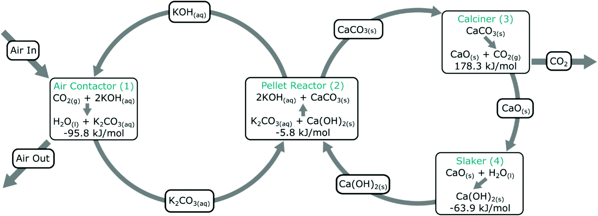 | ||
| Fig. 3 Carbon Engineering DAC process. An aqueous alkali hydroxide solution is used for CO2 capture from air in the contactor, which is subsequently contacted with Ca(OH)2 to form CaCO3 and regenerate the aqueous alkali hydroxide solution. CO2 is produced in a second cycle, which also produces CaO, which is slaked to regenerate CaCO3. Taken from ref. 167. Reprinted from Keith et al., A process for capturing CO2 from the atmosphere, Joule, 2, 1573–1594, Copyright (2018), with permission from Elsevier. https://www.sciencedirect.com/journal/joule. | ||
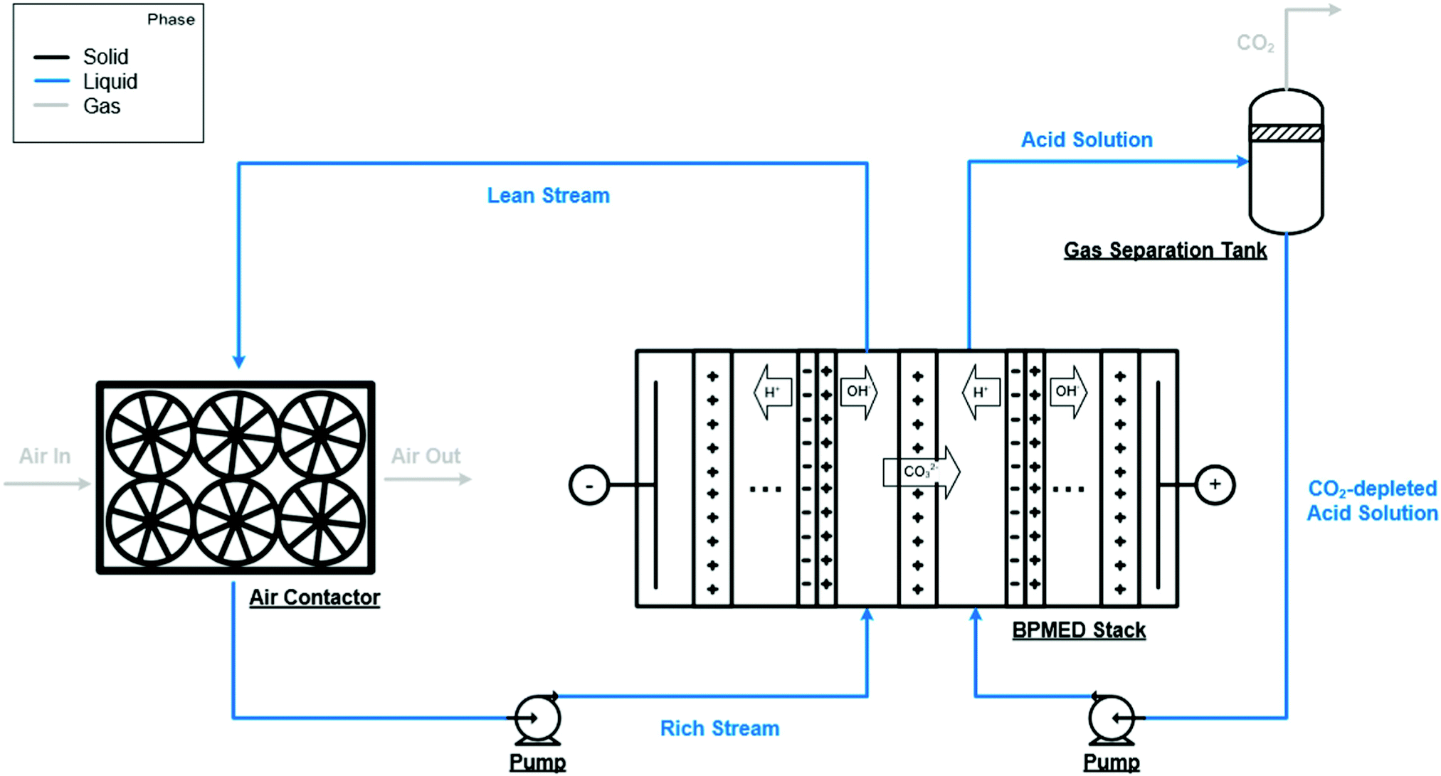 | ||
| Fig. 4 An alternative aqueous alkali hydroxide solution regeneration strategy. Instead of precipitation of solid carbonates, this approach relies on a bipolar membrane electrodialysis stack employing anion-exchange membranes to regenerate aqueous alkali hydroxide solution and to produce CO2. Taken from Evaluation of a direct air capture process combining wet scrubbing and bipolar membrane electrodialysis, ref. 207, licensed under CC-BY-NC-ND 4.0. | ||
Potential for and limitations of alternative liquid sorbents for direct air capture. Aqueous amine solvents are at the core of commercial absorption processes for the capture of CO2 from concentrated sources, having been used since ∼1930,209 yet there are few studies on their application in DAC.210–215 Screening of aqueous amines has shown that numerous amines can achieve a similar percentage capture as compared to commonly suggested liquid sorbents for DAC (e.g. hydroxides), but with the potential for energy saving due to their lower regeneration temperature.212 The rapid and high-yield formation of amine carbamate (as opposed to e.g. carbonates and bicarbonates) in sterically unhindered amines provides the highest percentage capture from air. However, the decomposition of carbamate in the regeneration stage is slow, and therefore, during rapid cycling, the capacity (or percentage capture under the same capture conditions) can decrease. The use of a catalyst added to the amine to aid regeneration appears to help rectify this situation.213 It is important to note however, that early appraisals of DAC with amine solvents highlighted that the evaporative loss of amines, which are poorly stable in air, would lead to intolerable economics (and in some cases, toxic emissions).165 Indeed, recent process modelling work on DAC showed that additional plant would be required to reduce such evaporative losses, and that new amines with negligible vapour pressures are necessary to reduce capital costs from initial estimates on the order of 103 $ per tCO2.216 New amines are under development for DAC, however, the focus thus far has been on hydrophobic amines to tackle water co-absorption issues (which leads to a higher energy requirement during regeneration of the amine).214,215
To overcome some of the issues above, aqueous amino acids have been investigated for DAC, as they are non-volatile and environmentally friendly.217–221 The approach generally relies on the crystallisation of a guanidinium carbonate salt of low aqueous solubility, which upon heating regenerates the amino acid sorbent (guanidine) and releases CO2. As this stage is endothermic, concentrated solar power has been used as an energy input, to try to improve the sustainability of the process.218 Recent work has taken advantage of the structural diversity offered by the platform to improve the cyclic capacity of the system, with initial regeneration energy requirements on the order of 100 GJ per tCO2.222,223
Ionic liquids (ILs) can have high CO2 capacities and offer negligible volatility; however, their high viscosities impose challenges for handling and gas–liquid mass transfer limitations. Thus, there have been very few studies for DAC-related applications.224,225 In an attempt to overcome the challenges above, the 1-ethyl-3-methylimidazolium 2-cyanopyrolide IL was encapsulated and tested for application in indoor air quality control (>1000 ppm CO2).224 Encapsulation increased the gas–liquid interfacial area and will likely permit simpler handling. The encapsulated ILs show comparable sorption capacities to a standard zeolite (13X), but with significantly lower regeneration temperatures and with better stability under humidity (and selectivity over water). To improve absorption rates, which is particularly important for DAC, as compared to capacity,226 the same IL was also mixed with ethylene glycol to form a deep eutectic solvent with lower viscosity.225 For ILs to be a reasonable option for DAC, more work on these major limitations would first be necessary.
 | ||
| Fig. 5 CO2 capacity and amine efficiency of a PPI-silica solid sorbent during temperature-swing cycles. (a) Adsorption was carried out under 400 ppm CO2/N2 at 35 °C for 60 minutes, with desorption under N2 at 110 °C for 10 minutes and, (b) amine efficiency as a function of cycle number. Taken from Oxidatively-Stable Linear Poly(propylenimine)-Containing Adsorbents for CO2 Capture from Ultradilute Streams, ref. 227. | ||
Other recent works with amine-based solid sorbents have considered issues relevant to scale-up, such as sorbent lifetime,236 fabrication of contactors,237 alternative silica supports,238 and detailed process modelling.239 For example, PPI-silica sorbents aged under air for 2 years showed minimal degradation (∼20% drop in CO2 capture from air capacity), although accelerated oxidation had a more significant impact on the sorbents applied to DAC compared to those applied to capture from more concentrated sources (a ∼40% drop in capacity after 12 hours under ∼0.04% CO2) (Fig. 6).236 PEI-infused cellulose acetate-silica fibres have also been studied as a proof-of-concept for scalable, structured DAC contactors.237 Using a combined temperature-vacuum swing regeneration, with dry air as an input, 98% CO2 was produced. With a wet air input ∼65% CO2 was produced (co-captured water would have to be condensed in a real process to produce high-purity CO2).
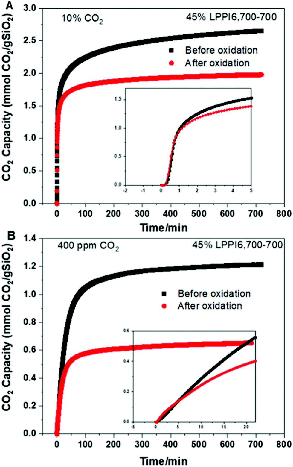 | ||
| Fig. 6 Effect of accelerated oxidation on CO2 capacity of PPI-silica solid sorbents under (A) 10% CO2 and (B) ∼0.04% CO2, showing a more significant impact on sorbent capacity under DAC conditions. Taken from ref. 236. Reprinted (adapted) with permission from Rosu et al., Effect of extended aging and oxidation on linear poly(propylenimine)-mesoporous silica composites for CO2 capture from simulated air and flue gas streams, ACS Appl. Mater. Interfaces, 12, 38085–38097. Copyright 2012 American Chemical Society. | ||
In terms of alternative silica supports, silica gels offer lower costs and are available in larger quantities compared to the ordered mesoporous silica frameworks typically employed in DAC studies, but due to their lower surface areas would be expected to perform poorly. However, recent work has shown that the addition of water during the amine grafting process (to generate surface hydroxyl groups for amine attachment) results in sorbents that appear to be competitive with those employing mesoporous frameworks.238 Similarly, water also plays a significant role during capture; for example, the amine-based sorbent Lewatit® VP OC 1065 (a polystyrene matrix with amine groups “believed to be (very similar to) the adsorbent that Climeworks uses in their first-generation DAC process”)239 shows humidity-enhanced sorption of CO2. Recently, detailed water and CO2 (co-)adsorption isotherm models have been developed for a DAC system based upon such solid amine sorbents, which is an important step to enable the benchmarking of sorbents and more accurate process modelling.239
Opportunities and challenges for other amine-functionalised solid direct air capture sorbents. In an attempt to address perceived issues related to capacity, hydrothermal stability (e.g., during steam regeneration of sorbents), and limited multi-cycle durability of amine-based silica sorbents, exfoliated mixed-metal oxides (MMOs) (derived from layered-double hydroxides) and layered-double hydroxides have also been tested for DAC.240,241 The unique nanostructure of MMOs (slit-shaped mesopores and broad pore-size distribution) results in uniform dispersion of the amines and good accessibility for CO2.240 The strong interaction between the MMO surface and amine results in good thermal, chemical and hydrothermal stability, with initial multi-cycle studies showing good durability.241 Future work on metal oxide-supported amines will need to carefully consider the role that the support plays (as compared to silicas), as it has been noted that e.g. basicity impacts surface speciation, amine-amine interactions and heats of adsorption etc.242
Metal–organic frameworks (MOFs) are of interest for gas separations generally due to the tunability of their chemistry (of the framework, and for post-synthetic modification).243 For application as chemisorbents in DAC they must offer durability under moisture, which is atypical for MOFs generally, and be amenable to amine functionalisation. MIL-101(Cr) has been studied as it is water stable and offers multiple avenues for amine functionalisation (adsorption of amines onto metal sites or physical impregnation with liquid amines). A balance between low CO2 uptake with low amine loading, and high CO2 uptake but poor kinetics due to pore blockage or loss of amines at high amine loading has to be considered.244 The Mg2(dobpdc) family of MOFs capture CO2 using a cooperative insertion mechanism whereby CO2 is inserted into the metal-amine bond to form ammonium carbamate chains. Therefore, the metal-amine bond strength is a tuneable parameter, where the framework metal, or the attached amine can be varied (Fig. 7).245,246 Although the mmen-Mg2(dobpdc) MOF has shown very high adsorption capacities under equilibrium isotherm studies at ∼0.04%, the unique adsorption isotherm shape and kinetic factors significantly reduce the capacity under more realistic flow geometries, strongly suggesting that adsorption isotherms alone can have limited utility in predicting behaviour in realistic DAC systems.247 Furthermore, the stability of powders under humidity is an issue, although strategies related to preparing composites with hydrophobic binders are beginning to appear, which may also help address issues related to e.g., pressure drop and handling during application.248 Finally, it has been suggested that the current cost of MOFs makes their use in DAC prohibitively expensive.173 Notably, however, Mosaic Materials are developing CO2 capture and indoor air quality control technologies based upon the use of MOFs (Table 1).
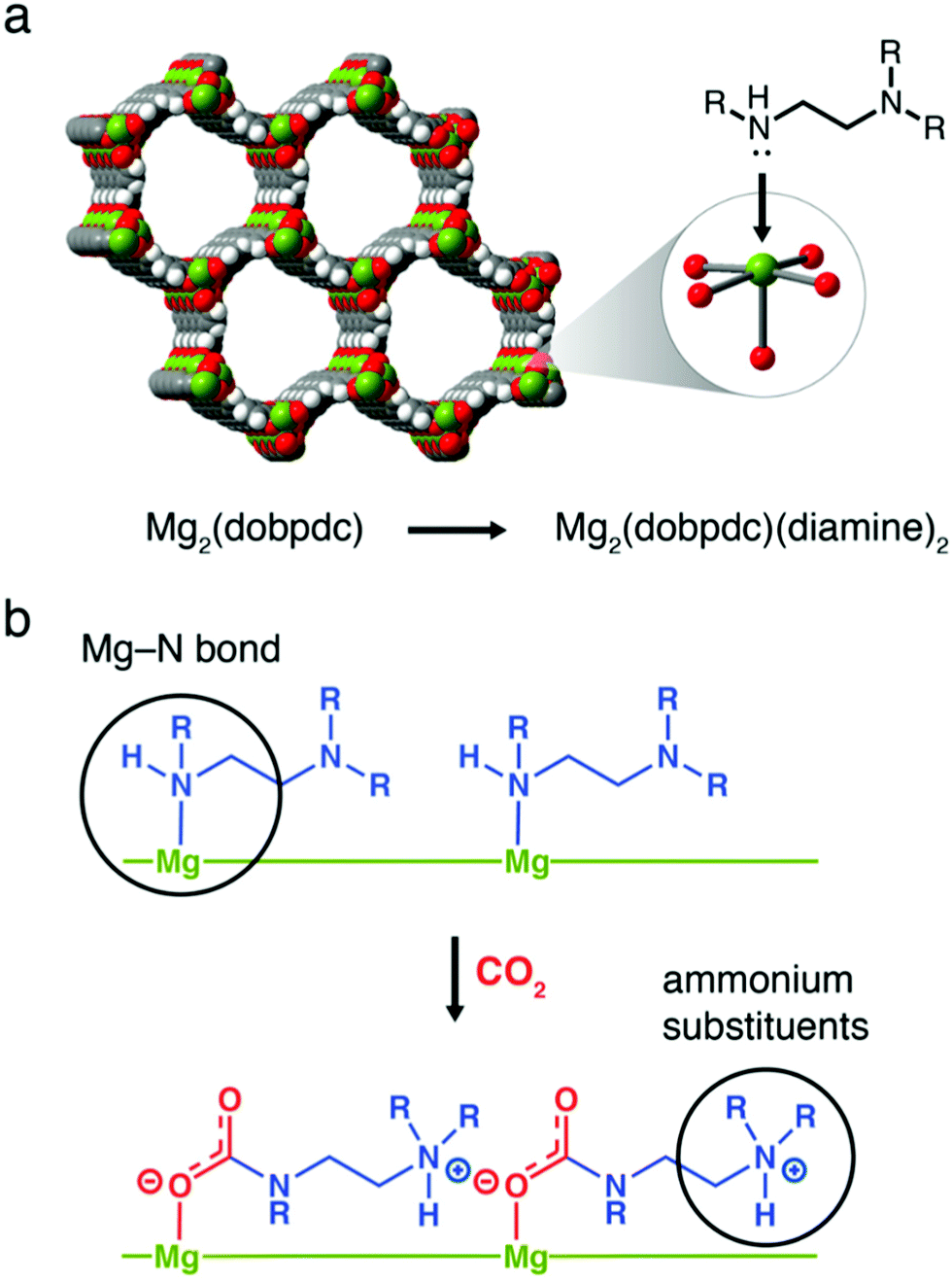 | ||
| Fig. 7 Cooperative insertion mechanism in Mg2(dobpdc) MOFs. (a) Structure of Mg2(dobpdc) and, (b) the formation of ammonium carbamate chains by cooperative insertion of CO2. Taken from ref. 245. Reprinted (adapted) with permission from Siegelman et al., Controlling cooperative CO2 adsorption in diamine-appended Mg2(dobpdc) metal–organic frameworks, J. Am. Chem. Soc., 139, 10526–10538. Copyright 2017 American Chemical Society. | ||
Alternative solid CO2 sorbents and the opportunities they offer for developing new direct air capture technologies. Polymeric ionic liquids (PILs) offer similar synthetic flexibility to ILs but with stability akin to macromolecular frameworks. The introduction of CO32− ions into quaternary-ammonium-based PILs results in a sorbent which captures CO2 when dry and releases it when wet, opening the possibility of a moisture or humidity swing approach (as opposed to e.g., pressure or temperature). Thermodynamic analysis implies that as the hydration sphere of the CO32− ion decreases, it becomes favourable to form HCO3− and OH− ions, which in turn bind less water than the CO32− ion. Thus, when dry, more OH− ions are available to capture CO2.249,250 Recent direct experimental evidence (NMR) has challenged this mechanism, stating that as the sorbent dries, water is released from the hydration sphere of OH− ions, and CO2 reacts with OH− ions to form HCO3−.251 Regardless, as water and CO2 sorption are now opposing, this offers the possibility of avoiding heating or cooling the contactor. In fact, the release of water from the sorbent as CO2 binds results in a cooling of the sorbent, a somewhat counter-intuitive ‘spontaneous cooling absorption’ phenomenon (Fig. 8).252 An increase in CO2 concentration of two orders of magnitude (compared to air) has been shown to be possible, and the release of free energy as a result of water evaporation drives the process.173 The general approach may have limited utility in cold and humid weather, as due to the underlying mechanism water could condense on the surface.253 The choice of anion (e.g. CO32−, F−, C2H3O2−, etc.) impacts upon whether the resulting sorbents are more suitable for moisture-swing DAC, or thermal regeneration in more conventional scenarios,254 and the choice of amine functional group also impacts performance.255 Porous (as opposed to dense), high aspect-ratio fibres have been investigated as a sorbent support structure for application in DAC,256 with ongoing work seeking to use biomass-derived materials as lower-cost and more sustainable supports.257,258 Overall, the general strategy has largely been developed by Lackner as a moisture-swing sorbent approach, with ion-exchange resins as the basis for the planned MechanicalTrees™ demonstration which aims to produce 95% CO2.179
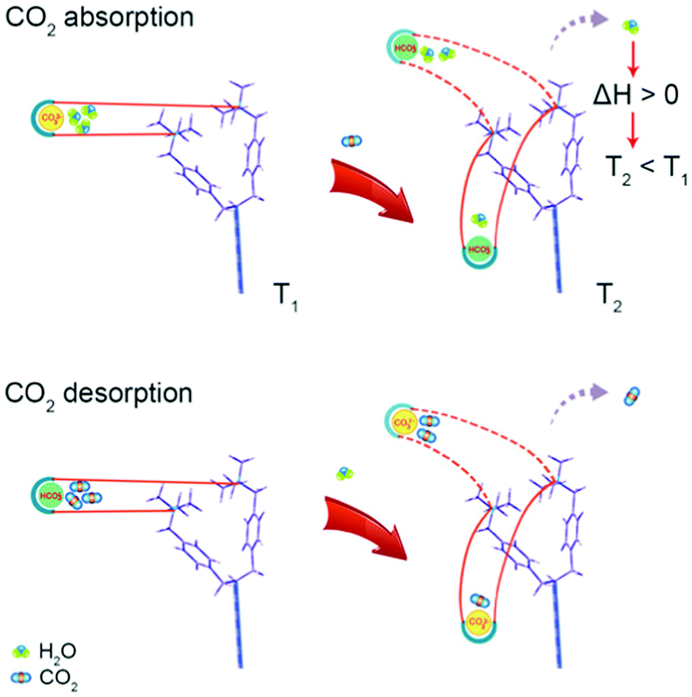 | ||
| Fig. 8 ‘Spontaneous cooling absorption’ phenomenon in polymeric ionic liquids with quaternary ammonium ions. As CO2 is absorbed, the desorption of water results in a release of free energy and a decrease in temperature. Taken from ref. 252. Reprinted (adapted) with permission from Wang et al., Spontaneous cooling absorption of CO2 by a polymeric ionic liquid for direct air capture, J. Phys. Chem. Lett., 8, 3986–3990. Copyright 2017 American Chemical Society. | ||
Calcium looping, (CaL), the cyclic carbonation and calcination of lime-based sorbents, is a promising strategy for CO2 capture from concentrated sources, particularly in the cement industry due to spent-sorbent recycling synergies.162,259 The bulk carbonation of lime-based sorbents (i.e., absorption of CO2 into the bulk of CaO),260 occurs at ambient conditions, with water playing a key role; negligible carbonation of CaO is observed in packed-bed reactors without both the pre-hydration of CaO to form Ca(OH)2, and the use of air with high relative humidity.261 Similar observations have been made for the regeneration of spent CaO discharged from the calciner of traditional CaL; moisture in the air ‘passively’ reactivates the sorbent for CO2 sorption by forming Ca(OH)2 and modifying surface and pore characteristics.262 Adopting this ‘passive pre-hydration’ strategy, whereby lime was exposed to a controlled humidity environment before DAC, it has been shown that the higher the relative humidity during lime storage/pre-treatment, the greater the degree of CO2 capture.263 In fact, only after high relative humidity storage is significant carbonation observed; at low relative humidity CO2 is likely captured by dissolution in physisorbed water on the surface of lime. Also, in a fluidized bed arrangement, significant pre-hydration of lime improved its fluidisation behaviour. Note that these tests were performed with dry CO2 at 0.04% to study the effect of pre-hydration in isolation. Calcination conditions have also been studied at pilot-scale using a high water vapour (21 and 35% vol) content gas as a fluidisation medium.264 The calcined materials were subsequently exposed to ambient air reaching a carbonation conversion of 55% after 14 days. Under simpler DAC conditions, i.e., without humidity control and with lime exposed to the air as a thinly spread layer, again the importance of the humidity of the air was noted, with differences in the rate and extent of carbonation found for sorbent applied indoors (low relative humidity) and outdoors (high relative humidity).265 Granulated and pre-hydrated lime achieved 50% conversion to CaCO3 after ∼170 h, compared to ∼450 h for lime. On the scale of weeks or months, high CaCO3 conversions were noted (∼75%), suggesting that like EW strategies, large areas of land would be required.
Modified CaO-based materials have also been investigated for DAC. Ethanol treated sorbent was exposed to air to assess its CO2 uptake potential. Different variables such as the effect of pre-milling, exposure time and the addition of alkaline water were investigated.266 The ethanol-treated material presented a carbonation yield of 20.4% compared to 2.4% for commercial lime after 7 days. The authors also observed that increasing the liquid to solid ratio leads to a higher CO2 uptake, but a trade-off should be considered between the solvent used and the desired carbonation conversion. Milling the slurry or adding alkaline water to the material improved the carbonation yield even further. Magnesium hydroxide (Mg(OH)2) has also been considered for this application. Magnesite (MgCO3) is calcined to produce pure CO2 and magnesium oxide. However, the mechanism of this reaction and the effect of different factors such as humidity, temperature and particle size has not been fully described for DAC. Therefore, more research is needed to assess the suitability of magnesite for DAC, particularly as the enthalpy of decarbonisation is 66% lower than that of limestone.267
Recent work sought to model the integration of lime-based DAC with a solid-oxide fuel cell (SOFC) where the high-grade heat from the SOFC is used to calcine the sorbent before DAC.268 This system has the benefit of providing high-efficiency power and DAC, which gives an opportunity to meet costs via electricity sales and carbon taxes. The importance of the choice of lime-based material was highlighted as it impacted on the thermal efficiency, the extent of CDR, and whether a ‘once-through’ (as was studied) or cyclic process would be more suitable. A range of further research avenues were provided,268 and it appears that a similar process is being developed by Origen Power (Table 1).197 Finally, it is also important to highlight that other related solid oxide, hydroxide and carbonate systems are under investigation for cyclic absorption DAC processes.269–271
Challenges for physisorbents in direct air capture and inspiration for improvements from enzymes and drug binding. All deployed sorbents for DAC to date are chemisorbents. However, physisorbents have been used to pre-treat air (to remove CO2 and water) prior to e.g., cryogenic air separation technologies. Thus, early work on a number of physisorbents for DAC found that the major limitation is the poor CO2 selectivity with respect to water,272 and that water vapour leads to sorbent degradation during e.g., sorbent storage in specific cases.273 Additionally the capacity for CO2 is typically low (due to the low heat of adsorption).173
The control of pore size and chemistry has been highlighted as a key route to improving physisorbent DAC performance (Fig. 9).274 Indeed, work with hybrid ultramicroporous (<0.7 μm) materials (HUMs, similar to MOFs but using both organic and inorganic linkers, hence hybrid) has shown that the combination of strong electrostatic interactions with CO2 along with hydrophobicity in ultramicropores may be a fruitful strategy to pursue.275 For example, in SIFSIX-18-Ni-β, the introduction of hydrophobic methyl moieties to the SIFSIX framework supplemented the strong interactions between C (of CO2) and F moieties (of SIFSIX) to break the typical selectivity issue (Fig. 10). Notably, this work tested separation of CO2 from sources with CO2 concentrations of >1000 ppm, i.e., targeted for indoor air quality control where faster and less energy-intensive regeneration of sorbents may be beneficial and indeed necessary.
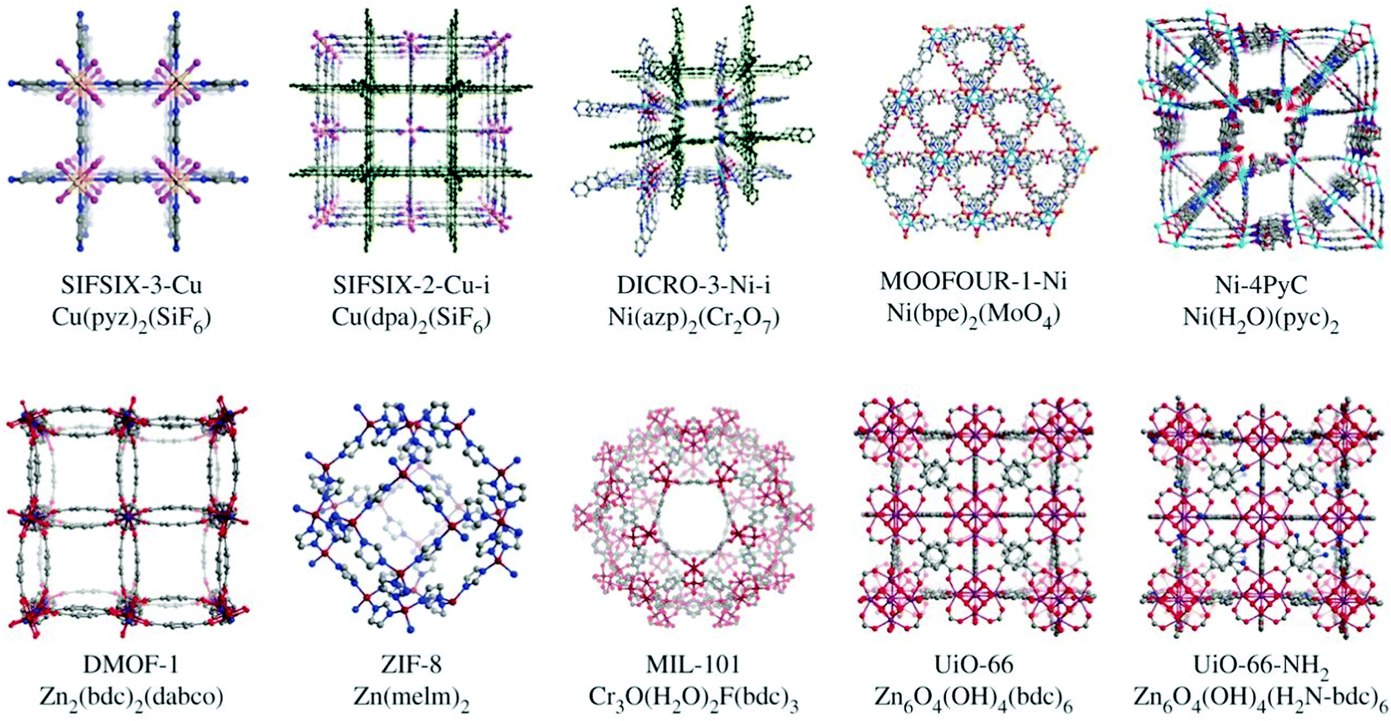 | ||
| Fig. 9 Benchmark metal–organic framework materials investigated for DAC. The synthetic flexibility, control over pore size and pore chemistry can be harnessed to produce MOF-based physisorbents that overcome issues related to selectivity for CO2 over water. Taken from ref. 274. Republished with permission of The Royal Society (UK), from Flue-gas and direct-air capture of CO2 by porous metal–organic materials, Madden et al., 375, 2084, 2017; permission conveyed through Copyright Clearance Center, Inc. | ||
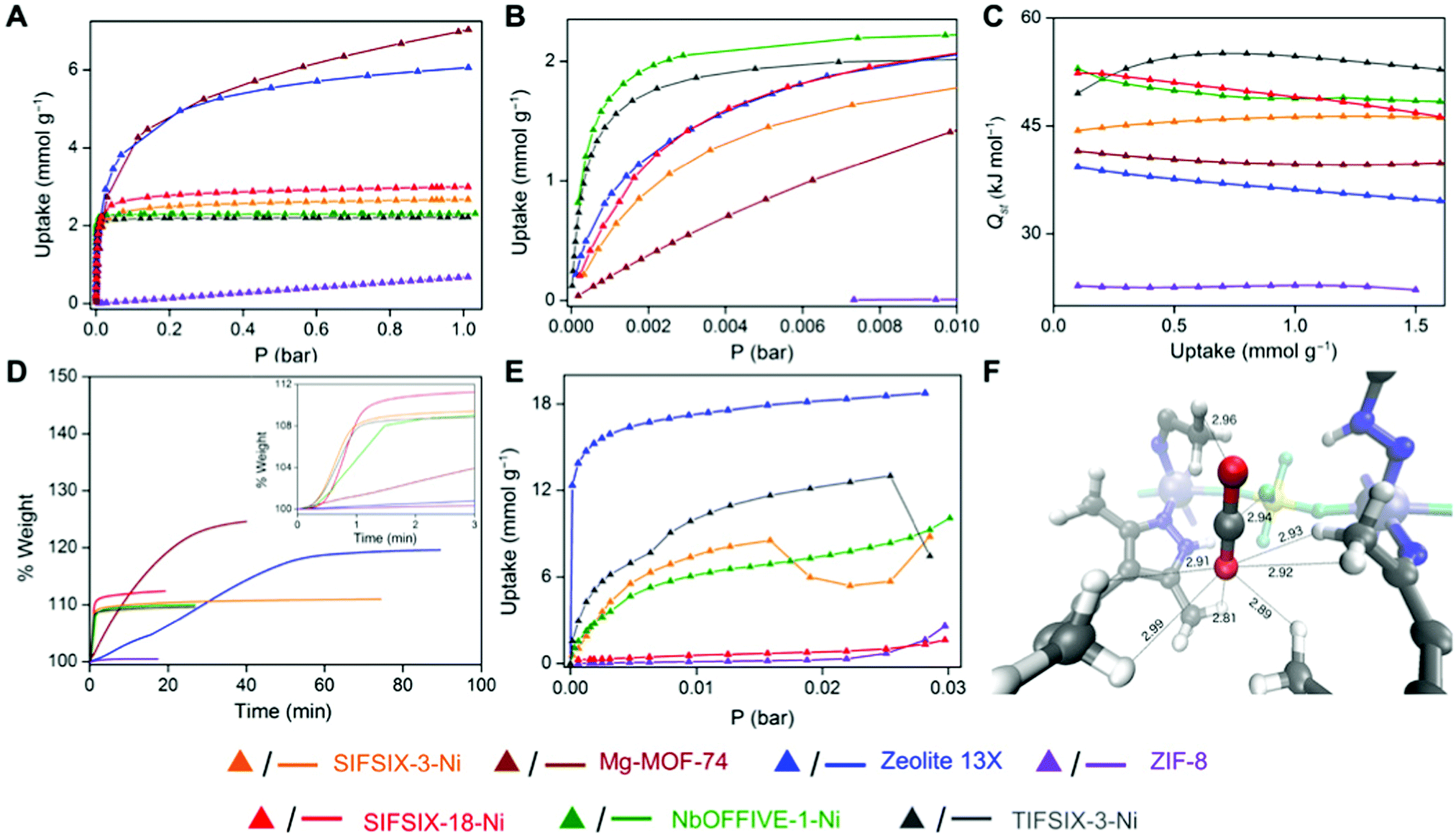 | ||
| Fig. 10 Low-pressure CO2 capture using porous frameworks. (A and B) Low-pressure CO2 isotherms at 298 K, (C) Isosteric heat of adsorption profiles for CO2, (D) gravimetric CO2 uptake at 1.0 bar with time at 303 K, (E) dynamic vapour sorption isotherms for water at 298 K and, (F) CO2 binding sites in SIFSIX-18-Ni-β determined by ab initio periodic computation. SIFSIX-18-Ni-β has reasonable CO2 sorption capacity (A and B) as compared to other physisorbents, but fast kinetics (D) and low water uptake (E), which taken together provides promise for its use as a physisorbent for low-pressure CO2 capture. Taken from Trace CO2 capture by an ultramicroporous physisorbent with low water affinity, ref. 275, licensed under CC BY-NC 4.0. | ||
It has been highlighted that physisorbent materials like those above mimic the ribulose-1,5-bisphosphate carboxylase/oxygenase (Rubisco) enzyme (the primary CO2 acceptor in plants) by exploiting multiple binding sites optimised from both a kinetic (pore size) and thermodynamic (polarizability) perspective.272 The general approach, precisely endowing porous frameworks with complex arrangements of moieties to break the selectivity issue,276 has also been investigated for CO2 capture from more concentrated sources.277 Here, ‘pockets’ which reject water but adsorb CO2 were termed ‘adsorbaphores’ (from pharmacophores for drug binding), with large-scale screening of databases of hypothetical structures used to guide synthesis of promising candidates. Approaches such as these could conceivably aid in guiding the design of entirely new frameworks, or in improving porous frameworks that appear to show promise for DAC (but which have yet to be tested in situations containing water vapour).278,279 Alternatively, recent work has shown that preparing well-dispersed MOF nanocrystals on hydrophobic supports improves the adsorption efficiency of MOFs under DAC conditions, whilst also reducing water adsorption by ∼25% (Fig. 11).280 These composite sorbents were prepared on a kilogram scale and underwent 2000 DAC cycles (with humid air), showing only ∼1% degradation in capacity, suggesting promise. A recent perspective on MOFs for low-pressure CO2 capture provides more detail.243
 | ||
| Fig. 11 Preparation of composite sorbent containing NbOFFIVE-1-Ni MOF and polyacrylate beads. The porous, hydrophobic polyacrylate beads prevent water from entering the inner structure of the sorbent which contains the NbOFFIVE-1-Ni MOF. Such an approach seeks to protect the MOF from water vapour in the air, whilst also dispersing MOF nanocrystals. Taken from ref. 280. Reprinted (adapted) with permission from Guo et al., A highly efficient and stable composite of polyacrylate and metal–organic framework prepared by interface engineering for direct air capture, ACS Appl. Mater. Interfaces, 13, 21775–21785. Copyright 2021 American Chemical Society. | ||
General contactor considerations for direct air capture application. First, it is important to note that a contactor with a high exposed specific surface area per unit volume can use a weaker sorbent to achieve the same amount of capture for a given contactor volume, i.e., there is a trade-off between the strength of the sorbent interaction with CO2 and the exposed surface area of the sorbent (noting of course that the strength of the sorbent interaction with CO2 also impacts sorbent regeneration conditions).175 Regardless of the nature of the sorbent, electrical fans (i.e., forced draft) have been required in all examples of commercial scale DAC, to overcome pressure drop in contactors. Thus, optimisation has been required between pressure drop and the quantity of CO2 removed, and between operating and capital costs (high air flows increase forced-draft costs but necessitate smaller contactors). Thus, pressure drop per unit surface area is a central concern for any DAC contactor; it has been described as “arguably the single most important efficiency metric”.281
Contactor design; comparison of innovation in liquid and solid sorbent contactors. In the most developed liquid sorbent system (i.e., Carbon Engineering),167,281 a high surface area contactor is continually renewed with a thin layer of aqueous alkali hydroxide solution that is pumped over a hydroxide-resistant PVC packing surface (Fig. 12). The high surface area is required to maximise air–liquid interfacial area, and the thin layer of liquid sorbent reduces liquid-phase diffusion resistance. Due to the low concentration of CO2 in air, the required liquid-to-gas flow ratio is far lower than is typical for gas separations, which reduces the liquid pumping requirements but gives rise to difficulties in keeping the packing surface wetted (which can be overcome by pulsing the liquid flow).281 The gas flow is horizontal whilst the liquid flow is vertical (cross-flow). This unusual final design feature is described as a “crucial enabler of cost-effective DAC” due to the high cost of traditional counter-flow alternatives.167 As will be discussed below, the design of contactors for DAC requires a detailed design assessment, and the lack of air–liquid contactor designs in the literature is thus notable. For example, although membrane contactors can intensify gas–liquid sorption processes by providing an order of magnitude reduction in plant size compared to traditional solvent contactors (or a similar increase in surface area to volume ratio),282 the authors are not aware of studies on their application in DAC to date. Notably, however, they appear to be planned for use in commercial projects.186 Similar comments could be made for rotating-packed beds.
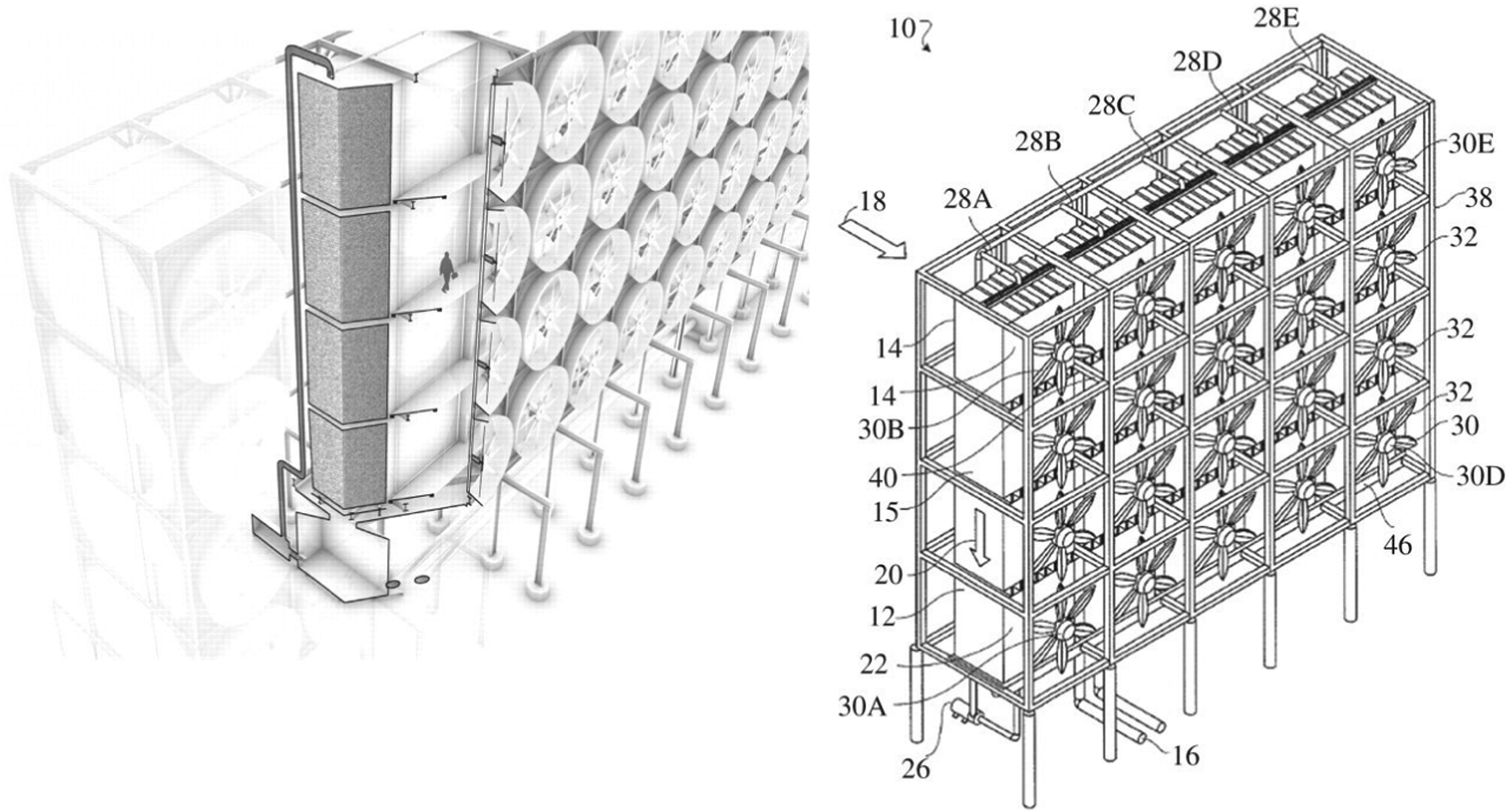 | ||
| Fig. 12 The Carbon Engineering contactor design featuring forced-draft fans and structure packing with cross-flow gas and a liquid feed. Taken from ref. 281 Republished with permission of The Royal Society (UK), from An air–liquid contactor for large-scale capture of CO2 from air, Holmes and Keith, 370, 1974, 2012; permission conveyed through Copyright Clearance Centre, Inc. | ||
By contrast, for solid sorbent DAC systems, contactors of monolithic,283,284 fibre,237,256 fluidized-bed,285 fixed-bed,206,286–292 and moving-bed designs,293,294 have all been investigated for DAC. The monolithic, fibre, fluidized-bed and fixed-bed concepts involve a temporal change in conditions to mediate sorption and desorption of captured CO2. Alternatively, a fixed-bed may be continuously replaced to create a moving bed, and fluidized beds can also be operated in a circulating mode, which spatially segregates sorption and desorption. In the final two arrangements there is always sorbent in sorption ‘mode’, at the expense of more complex sorbent handling mechanics. Having multiple fixed beds can of course also ensure that a portion of the sorbent is continually in sorption ‘mode’.287
Parallel channel cellular monoliths can offer low pressure drops and high mass transfer rates, with important considerations including cell density, cell wall thickness and sorbent loading/film thickness (Fig. 13). Thin cell walls are desirable, as they reduce the energy requirement during desorption (i.e., a smaller mass of ‘non-active’ component is heated). For similar reasons, a thicker sorbent film reduces the energy requirement during desorption (the same mass of ‘non-active’ component is heated but more CO2 is released).284 However both approaches are challenging during manufacture, due to the stability of the monolith and adhesion of the sorbent, respectively. As an alternative to a thicker sorbent film, a sorbent with a higher equilibrium capacity could, in principle, be used (noting that equilibrium sorption capacity is not always useful to assess a sorbents use in practice).239
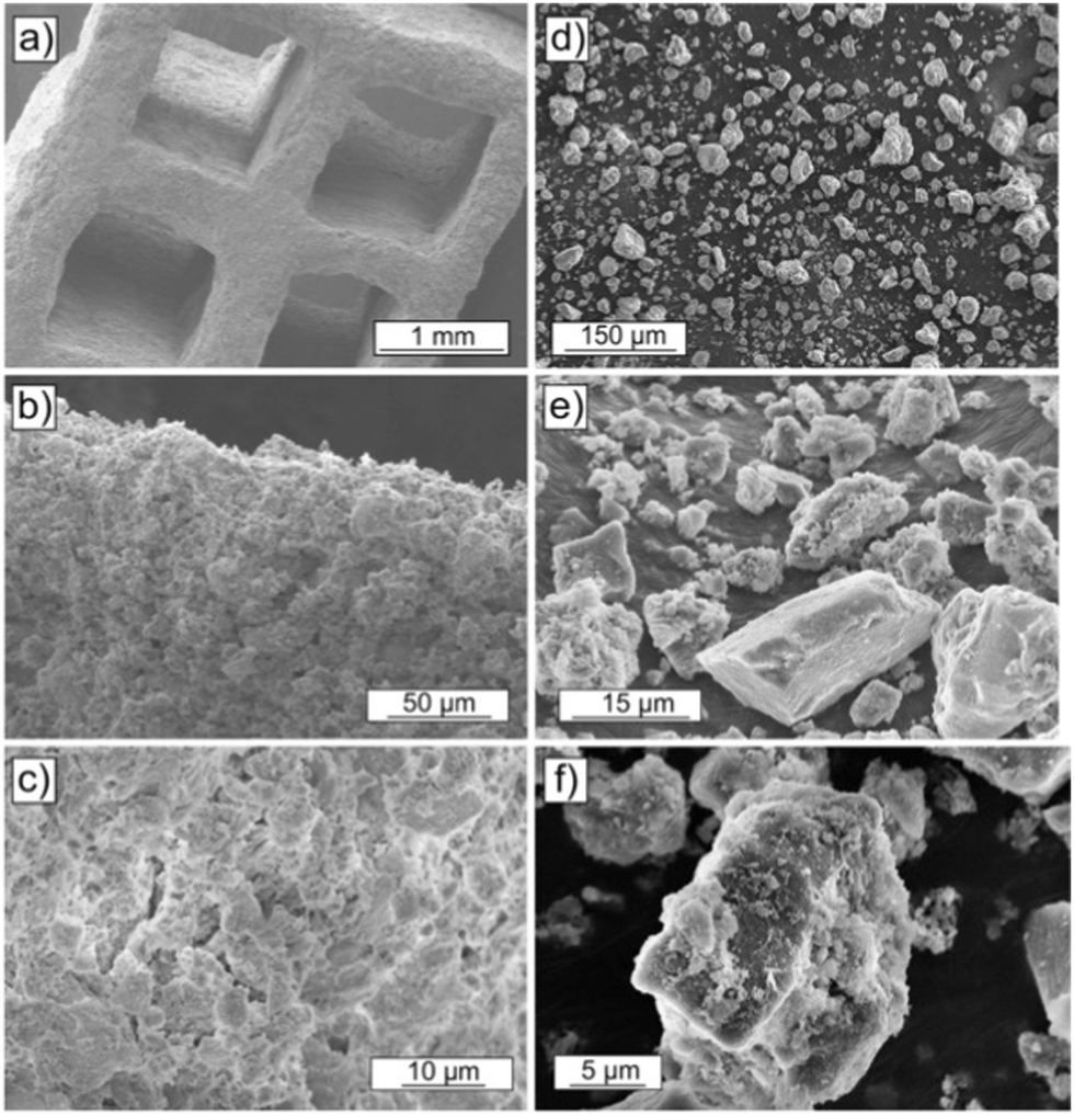 | ||
| Fig. 13 Comparison of the morphologies of monolith (a–c) and powder (d–f) (formed by grinding pieces of monolith) of a PEI-alumina DAC sorbent. Taken from, Poly(ethylenimine)-functionalized monolithic alumina honeycomb adsorbents for CO2 capture from air, ref. 283. | ||
Fibre contactors have also been shown to offer low pressure drops in DAC using solid sorbents.237 A direct comparison with a packed bed of the same sorbent material and with a comparable void fraction highlighted that packed beds give rise to high, intolerable pressure drops at the air velocities likely required for DAC. Similarly, fluidised beds can give rise to high pressure drops, as there may be an additional contribution to lifting (and, in some arrangements, circulating) the sorbent. Also, as pressure drop is proportional to the length of the sorbent bed, a small bed length may be necessary, which can be challenging to achieve with fluidised beds for a variety of reasons.286
It is important to highlight that the arguments presented above are somewhat simplistic, as changes in sorbent particle size, reaction kinetics, packing surface area etc. can all be modulated in such a way to claim an advantage over an alternative design. In all cases a detailed design assessment is required. As an example, the majority of early work by Steinfeld on DAC contactors for solid-supported amine sorbents focussed on fixed-bed arrangements,288–292 which later became the basis of the Climeworks contactor. More recently, moving-bed arrangements have been considered by others to avoid very low height/diameter ratios of contactors (a common design feature for the reasons identified above) and to reduce pressure drop and improve adsorption performance (Fig. 14).286,293,294 Here the sorption stage is mediated in a radial flow contactor, where air crosses the sorbent bed in the radial direction. Radial flow contactors first appear promising as they combine high volumetric adsorption rates to minimize contactor size and costs, and low pressure drops, which tackle capital and operating costs, respectively. But the point to be made, is that although such a contactor can be operated in a moving-bed arrangement, batch operation (akin to fixed-bed operation) appears to offer better capture efficiency in most DAC situations due to the high air velocity, highlighting again the complexity involved in contactor assessment.294
 | ||
| Fig. 14 Moving-bed contactor. Blue arrows indicate gas flow and red arrows indicate solid sorbent flow. Taken from CO2 Capture from air in a radial flow contactor: Batch or continuous operation? ref. 294, licensed under CC BY 4.0. | ||
Sorbent regeneration strategies in the laboratory compared to practical direct air capture application where high-purity CO2 is usually required. As above, it is also important to consider the production of high-purity CO2 following contacting, i.e., sorbent regeneration. We also know that it is inefficient to cool, heat or compress the entire air stream entering a DAC process.173 Thus, in a majority of cases the air entering a sorbent-based DAC process is at ambient or near-ambient conditions with the change in conditions to produce high-purity CO2 enacted during the sorbent regeneration stage. This approach excludes certain regeneration strategies that may be appropriate for capture from more concentrated sources. For example, a vacuum or pressure swing desorption (VSD or PSD) process would have to operate at <0.4 mbar during the regeneration stage, which is not a practical vacuum level to employ in a real process.295,296 Furthermore, any weakly-bound CO2 (e.g., physisorbed on a solid sorbent) would be desorbed from the sorbent during evacuation of the adsorption chamber to remove residual air (effectively ‘wasting’ capacity of the sorbent). Laboratory-scale research on sorbent processes for DAC has generally utilised temperature-swing desorption (TSD) with an inert gas purge to regenerate the sorbent and produce high purity CO2. The limitations of such an approach are discussed briefly here with comparisons made to the regeneration strategies employed in commercial DAC processes.
In practice, TSD would involve a significant energy requirement as the large mass being heated involves ‘non-active’ components of the DAC system. In the case of liquid sorbents, the specific heat capacity of water is important, as the amine and hydroxide solutions employed are mostly water. Whereas heating such a liquid sorbent is often an appropriate regeneration strategy for capture from more concentrated sources, heating of liquid sorbents has not been used in commercial DAC technologies. Instead, precipitation and heating of the resulting solid at high temperatures is favoured in the Carbon Engineering technology (ultimately delivering ∼97% CO2 at ∼150 bar).167 As above, electrochemical methods for liquid sorbent regeneration are also in development,207,208 and thus it seems likely that new liquid sorbent regeneration approaches will be a key opportunity for efficiency gains.
In the case of solid sorbents (typically solid-supported amines), as well as the specific heat capacity of the sorbent itself, ‘non-active’ components such as sorbent binders and the sorbent support structure/packing will impact the energy requirements during regeneration,175 and therefore should be considered during design. As laboratory-scale studies typically use an inert gas purge during TSD solid sorbent regeneration, this results in a dilute output stream with an unrecoverable fraction (the inert gas) and faster kinetics during desorption (due to the lower partial pressure of CO2 in the output stream).287,297 Such an approach can provide unrealistically optimistic results (unless low-concentration CO2 output streams are of interest).298
The combination of temperature and vacuum swing desorption (TVSD) can be used in practice to produce high purity CO2 following DAC,295 and is employed in the Climeworks technology (Fig. 15).299 Here, following adsorption the contactor is closed to ambient air, heat is delivered at <100 °C, and vacuum (at practically achievable levels) is applied to collect the CO2 and co-adsorbed water. Following condensation, CO2 is ultimately delivered at >99% at slightly elevated pressure.299 Steam-assisted TVSD (S-TVSD) utilises a steam purge to further lower the partial pressure of CO2, in turn providing a larger driving force for CO2 desorption.297 As the process operates under vacuum, steam can be generated at <100 °C, which opens the possibility of using solar energy or waste heat.296 For both TVSD and S-TVSD, complex relationships emerge between e.g., evacuation pressure, productivity, power and heat requirements, and capital and operating costs etc. which necessitates multi-dimensional optimisation.296,297,300,301
 | ||
| Fig. 15 A schematic of a simple temperature and vacuum swing DAC process. A full cycle includes evacuation of the adsorbent chamber, heating, a second heating step where CO2 is extracted for storage, cooling to protect the sorbent from oxidative degradation, exposure to the atmosphere and adsorption. Reproduced from ref. 239 with permission from the Royal Society of Chemistry. | ||
It is also important to highlight that although equilibrium sorption capacity is useful to compare sorbents at the laboratory scale, this metric is not very useful in assessing their use in practice, due to differences in the shapes of sorption isotherms and their dependency on temperature.239 Complex relationships emerge between e.g., sorbent working capacity, desorption temperature, productivity and energy requirements etc., again necessitating complex multi-dimensional optimisation.239,287,300 Additionally, weather conditions (humidity, ambient temperature etc.) can strongly affect performance.253,265,287,295 Overall, common laboratory sorbent regeneration strategies and sorbent capacity measurements have clear limitations when they are translated to practical DAC application.
3.3. Assessment of alternative processes for direct air capture
Whilst sorption-based DAC is now relatively well-established, there are several other process technologies at earlier stages of development for DAC. Here we assess those based on distillation, gas separation membranes, and electrochemical devices, highlighting areas where innovation is required and where such devices might be able to make an impact. We also assess very early-stage work on the direct conversion of CO2 from the air using engineered biological systems and chemical catalysis, comparing these to natural systems and catalytic processes using concentrated streams of CO2 following DAC, respectively. Finally, we reconsider contacting of CO2 in the air, seeking to assess scenarios where ‘passive’ contacting might be economically viable through e.g., integration with buildings.In Table 2 we attempt to summarise key figures of merit for various NETs and DAC processes, noting the difficulty in doing so rigorously due to the enormous variations in assumptions made across the different studies summarised. This is perhaps best captured by a quote related to the relatively well-established Carbon Engineering DAC process which states, “CE has spent several tens of millions of dollars developing DAC technology, yet our performance and cost estimates still carry substantial uncertainty.”167 Readers are therefore directed to the numerous caveats presented in the caption of Table 2 and the original cited works in all cases.
| a Note that these values are subject to significant change depending on the boundary conditions selected, amongst other concerns; it is therefore not straightforward to compare across rows given the enormous variation in the assumptions made across the different studies summarised here. Where 10x is provided, this implies ‘on the order of’. b CO2 flux values are subject to significant changes depending on e.g., point in time. c Studies may inconsistently apply TRL definitions; for this reason, the different entries are not always comparable. Where references are not provided, these values are based on the authors’ assessment and definitions used in ref. 98. d Some challenges will be common across options, e.g., at low TRL, raising R&D funding and successful demonstration will be essential, whereas at higher TRL, all options will require investment and supportive business and policy models, and will need to address public acceptance to obtain a social license to operate. CO2 storage will, across all relevant cases, be affected by regulation, compliance, and liability considerations. In this column we therefore highlight areas where the challenges are different from one option to the next. e In principle, limited by CO2 storage capacity and energy supply. |
|---|
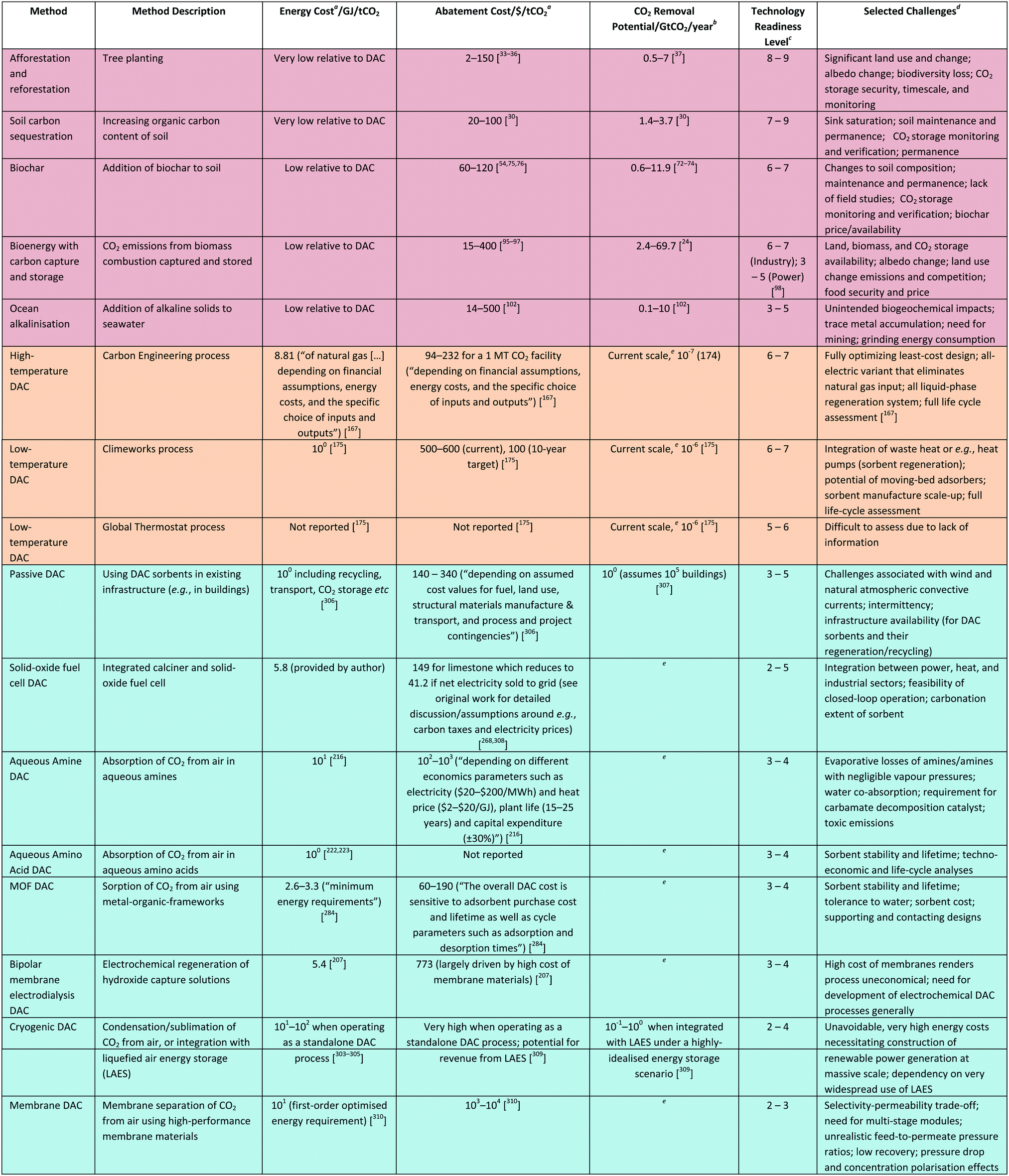
|
Notably, however, CO2 has a relatively high freezing temperature (−78 °C for CO2, compared to −210 °C for N2 and −220 °C for O2). Thus, CO2 and water are currently removed from air to protect downstream cryogenic plant during cryogenic air separation (to produce high-purity N2, O2, and Ar) as they would freeze and cause plugging. This removal has been mediated by aqueous alkali solutions, physisorption and molecular sieving. Similarly, in liquified air energy storage, where air is cooled to −196 °C, CO2 must first be removed from the air to protect the plant. Recent work has suggested that the potential value of CO2 removed from the air may influence the design of liquified air energy storage systems, i.e., encouraging the construction of larger plants near CO2 storage or utilisation facilities. Such systems could, in principle, contribute to CDR targets (on the order of 10−1 to 100 Gt per year).309 It is important to note that this work assumed a highly idealised energy storage scenario, where all energy storage was via air liquefaction or compression (amongst many other assumptions) to provide a first-order feasibility assessment.
A recent engineering parametric study investigated the impact of materials performance, process design and operating conditions on membrane-based DAC.310 The study concluded that with existing commercial membrane materials, the maximal CO2 output concentration from a single-stage separation would be ∼2%. A similar two-stage process could increase this to ∼50%, noting that O2 and water would be co-permeated. High-performance materials (not commercialised) could achieve ∼12% in a single stage, and up to ∼99% with two stages. For these high-performance materials in a two-stage process, costs would be on the order of 103 to 104 $ per tCO2 with a first-order optimised energy requirement on the order of 101 GJ per tCO2. Whilst deleterious effects such as pressure drop and concentration polarization may reduce this modelled performance further, clearly multi-stage membrane modules would be required to produce high purity outputs (Fig. 16). It is also very important to note that these results were achieved with very high feed-to-permeate pressure ratios (on the order of 100) and with a vanishingly low recovery, conditions very far from existing gas separation membrane processes and with large energy costs. Indeed, similar modelling work notes a multi-stage membrane process with materials offering a combination of very high permeability selectivity, as well as a pressure ratio >30, would all be required for a 1000-fold increase in CO2 concentration.315 Note that in this second work the permeability and selectivity values were taken from two different membrane materials, highlighting again the difficulty in achieving high permeability and selectivity in a single membrane material.
 | ||
| Fig. 16 Schematic of a multi-stage membrane DAC process. Taken from A new strategy for membrane-based direct air capture, ref. 315, licensed under CC BY 4.0. | ||
Facilitated-transport membranes (membranes containing carriers that ‘shuttle’ gas molecules) may provide opportunities to improve membrane performance in DAC, as they can achieve both high permeability and selectivity in a single membrane and are therefore particularly suited to dilute separations. However, work with fixed-carrier systems has thus far only resulted in output streams of 0.8% CO2 with a 3 bar air feed pressure.316 Very recent work on a mobile carrier system appears promising, and likely represents an important avenue for future development.317
Further to the electrochemical membrane examples for DAC involving an SOFC,268 and ion-exchange membranes to recover CO2 from liquid capture solutions presented above,207,208 a small number of electrochemical sorption approaches to DAC have been studied.318,322–325 These may be direct or indirect, where either the sorbent itself or a second species is redox active. In the latter case, the redox-active species competes with CO2 for sorbent affinity (thus releasing CO2 as it instead binds with the sorbent). As with chemical sorption methods, sorbent affinity for CO2 strongly influences the energetics, e.g., for weak adsorption, small potentials are required which leads to low faradaic efficiency. One recent example involves the reductive addition of CO2 to quinones, which has been tested with CO2 down to 0.6%, showing <30% loss of capacity after 7000 cycles (Fig. 17).318 In another arrangement, water electrolysis is used to produce hydroxide ions which combine with calcium ions from dissolved CaCO3 to generate Ca(OH)2. Upon contacting the Ca(OH)2 slurry with air, CaCO3 is regenerated. The protons generated from water electrolysis result in the liberation of CO2 from CaCO3, the regeneration of water and the continuous supply of calcium ions to close the loop.322 Additionally, examples are beginning to appear where electrochemically-driven pH swing methods are used to reversibly generate and consume hydroxide,323–325 and where electrochemical methods are used to separate CO2 from water or seawater as a potential alternative to DAC.326–330
 | ||
| Fig. 17 Electro-swing adsorption of CO2. Following the application of a reducing potential, carboxylation of quinone captures CO2. CO2 is released when the polarity is reversed. The inner polyvinylferrocene-containing electrode acts as an electron source and sink. Reproduced from ref. 318 with permission from the Royal Society of Chemistry. | ||
To further develop electrochemical processes for DAC generally, key challenges include reducing the cost of the materials employed within the devices (particularly the case for membranes), understanding the impact of other components of air (particularly O2), and gaining a deeper knowledge of molecular scale mechanism to further iterate materials design.
331 Whilst debate continues about the area required, it will necessarily be multiple orders of magnitude higher than that required for technological approaches to DAC.332 A potentially more feasible nature-based, engineered DAC approach is to consider plant-like species in Earth's waters. Although the area required may not be very significantly reduced, there is a larger potential deployment area for which there is less competition with e.g., farming, crop growth and housing. For example, microalgae (single-celled photosynthetic microorganisms) can convert dissolved inorganic carbon (e.g., HCO3−) into CO2 by photosynthesis at ambient conditions and fix the CO2 into biomass, with high photosynthetic efficiency (approximately an order of magnitude more efficient than terrestrial plants).89
Microalgae can survive in saline, alkaline and waste water, but high pH conditions increase the gas–liquid mass transfer rate of CO2 and biomass productivity, potentially increasing the feasibility of DAC (e.g., in nature, soda lakes encourage such microalgae processes).333,334 Suspension-based techniques, e.g., open ponds or photobioreactors, can have large land, water, energy and maintenance requirements, and significant gas–liquid mass transfer limitations. Open pond systems, however, are easily scalable and offer lower costs and energy requirements than alternative arrangements, with such an approach being piloted by Global Algae (Table 1).188 Recently, to tackle gas–liquid mass transfer limitation issues, carbonic anhydrase (CA) enzymes have been used to catalyse the gas–liquid reaction (CO2 to HCO3−), by cross-linking CA with glutaraldehyde and encapsulation into buoyant calcium alginate beads (Fig. 18).335 The buoyant beads float at the air–water interface of an open pond, ensuring that the enzyme is close to the interface. Encapsulation also protects CA from biodegradation and ensures that it is in a recoverable form. The use of encapsulated CA resulted in improved CO2 fixation rates and reduced water evaporation compared to controls. Alternatively, microalgae can be immobilised on a support, with recent work showing a significant enhancement in CO2 absorption rate and substantially reduced water use when microalgae were immobilised on fabrics, as compared to suspension controls (note that this work tested the approach using ∼5% CO2).336
 | ||
| Fig. 18 DAC by microalgae, catalysed by carbon anhydrase. Buoyant beads containing carbonic anhydrase float at the gas–liquid interface, acting as a catalyst for the CO2 to bicarbonate reaction. Taken from ref. 335. Reprinted (adapted) with permission from Xu et al., Direct air capture of CO2 by microalgae with buoyant beads encapsulating carbonic anhydrase, ACS Sustainable Chem. Eng., 9, 9698–9706. Copyright 2021 American Chemical Society. | ||
The first report on direct conversion of CO2 from the air used a homogeneous metal-catalysed approach to produce methanol.210 Air was bubbled through a pentaethylenehexamine (PEHA) solution, with a Ru-based hydrogenation catalyst (with H2 at 50 bar) used to mediate conversion to methanol. Up to 79% of the captured CO2 was converted to methanol. Later work developed a biphasic system to enable the efficient recovery and recycle of the amine and catalyst (again tested for DAC) (Fig. 19).337 An amine-free system (using the same Ru-based catalyst) employed an alkali hydroxide in ethylene glycol, and achieved quantitative conversion to methanol after 20 h at 140 °C with H2 at 70 bar.338 The addition of ethylene glycol enabled the conversion to methanol, as previous work with an alcohol-free system had resulted in formate formation.339 Other non-Ru-based catalysts systems have also been studied, but appear to suffer from poor selectivity for methanol,340 or are targeting more complex high-value chemicals.215 A full account of work in this area is available, highlighting that ongoing research seeks to develop the approach in a flow-system geometry to enable continuous production of methanol from air.341
 | ||
| Fig. 19 Schematic of a biphasic CO2 to methanol system, where CO2 is captured and converted from the air and the amine and catalyst are recyclable. Taken from ref. 337. Reprinted (adapted) from Kar et al., Integrative CO2 capture and hydrogenation to methanol with reusable catalyst and amine: Toward a carbon neutral methanol economy, J. Am. Chem. Soc., 140, 1580–1583. Copyright 2018 American Chemical Society. | ||
Inspired by the high reactivity of hydrides with CO2 under mild conditions, ILs with BH4− ions have also been studied for capture and conversion of CO2 directly from air.342,343 Competition between hydrolysis of the BH4− and CO2 reduction is observed, with significant conversion to products taking a number of days. Recovery of the IL is possible by introducing hydrochloric acid to form formic acid.
Approaches which integrate solid sorbents and heterogeneous catalysis appear to be in the early stages of development.344–346 Early examples involved a DAC sorption stage followed by methanation of CO2 over a Ru catalyst.347,348 However, a ‘dual function material’ has recently been proposed which combines DAC and methanation functionality in a single material, potentially avoiding penalties associated with e.g., a temperature swing and subsequent catalytic conversion.346 In this case, NaO and Ru are dispersed on an Al2O3 support, acting as capture and conversion agents respectively. At ∼320 °C CO2 is adsorbed and upon addition of H2, converted to CH4. A similar process using a Ni/Na-γ-Al2O3 dual-function material has also been proposed; 100 ppm CO2 feeds were converted to 11.5% CH4 in a cyclic sorption and hydrogenation process.349
Lackner's moisture-swing sorbents are currently being commercialised as MechanicalTrees™, whereby tiles made from moisture-swing sorbents are raised in a column to capture CO2 from the air. Once saturated with CO2, the tiles are lowered into the base of the column for recovery before subsequent water and CO2 separation. It is claimed that up to 95% CO2 can be produced.179 In another arrangement, ‘shading devices’ fabricated from the moisture-swing sorbents are envisaged as components of building facades that both mediate DAC and reduce the solar heat gain of buildings.307 Such an arrangement may enable DAC in congested cities. However, as the sorbent is now static, the moisture-delivery system must move (like an automated window-cleaning system). It is suggested that many buildings using this design, on the order of 105, would be required to achieve capture rates on the order of 100 Gt per year.
Ca(OH)2 panels have been envisaged as being deployed as recyclable components of buildings or as components of larger, centralised installations in open fields (Fig. 20).306 The volume of these structures would be 1 to 2 orders of magnitude larger than those of typical DAC contactors (on a m3 per tCO2 basis), but with the advantage that the materials are available at very low cost, and the recycling to produce concentrated CO2 and return the Ca(OH)2 relies on existing technology (oxy-fuel combustion to calcine CaCO3 to CaO, which is hydrated to produce Ca(OH)2). A first order cost estimate was proposed as 102 $ per tCO2 for the overall technology (i.e., including fabrication, installation, transport, recycling and CO2 transport and storage etc.), which appears to be competitive with other DAC technologies, although with (as above) much larger contactor volumes.
 | ||
| Fig. 20 Evolution of CO2 concentration at various scales within porous Ca(OH)2 plates fabricated into large structures. From right to left: interior of plate, between plates, stacked plates, and installation of stacked plates. Reproduced from ref. 306 with permission from the Royal Society of Chemistry. | ||
Leveraging existing industrial infrastructure may also be able to provide passive air contacting (note that one of the commercial designs for contacting liquid solvents with air was derived from wet cooling tower technology).167 For example, it has been proposed that natural draft dry cooling towers could, in principle, reduce the electrical energy requirement of mechanical fans to move air.350 Similarly, solar updraft towers may be able to provide high flowrates of air without an electricity input, and as such their use in a DAC system has also been considered recently (Fig. 21).351
 | ||
| Fig. 21 Schematic of an integrated thermochemical water splitting and DAC process, using a solar updraft air tower for passive contacting. Taken from Integration of thermochemical water splitting with CO2 direct air capture, ref. 351, licensed under CC-BY-NC-ND 4.0. | ||
Finally, passive contactors appear in somewhat related dilute separations, including in uranium recovery from seawater (∼3 ppb). As there is ∼4 Gt of uranium in seawater, efficient extraction could have profound effects on the nuclear industry.352 The proposed technology relies on amidoxime functionalised polymers which are braided and attached to a weight. The weights are sunk, with the braids floating vertically and exposed to sea currents, which mediate mass transfer (Fig. 22). The best estimates of current technology costs are on the order of 106 $ per tU, which is more than an order of magnitude more expensive than the current market price of uranium (not significantly dissimilar to DAC).352 Recent work highlights that modification of the braids with electrochemically-mediated sorbents may be able to reduce current technology costs to a level where they would compete with traditional sources of uranium.353 Regardless, the overall concept supports the idea of passive contactors for dilute separations, and it is not difficult to envisage an above-ground DAC equivalent, e.g., ‘sails’ or canopies fabricated using, for example, the fabric-supported microalgae discussed above.336
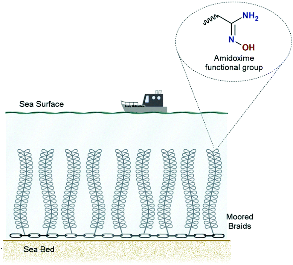 | ||
| Fig. 22 Schematic of a braided adsorber system for uranium removal from seawater. Taken from ref. 352. Reprinted from Dungan et al., Uranium from seawater – Infinite resource or improbable aspiration? Progress in Nuclear Energy, 99, 81–85, Copyright 2017, with permission from Elsevier. | ||
4 Feasibility of direct air capture; techno-economic analysis and life-cycle assessment
4.1. Techno-economic analysis
Early estimates of DAC costs indicated that the technology may not be economically viable. One of the first estimates for high-temperature DAC was provided by Duong and Keith,354,355 who assumed CO2 is removed from the air using hydroxides, such as NaOH and Ca(OH)2. Their work indicated that the cost of CO2 removal may reach 500 $ per tCO2, but potential reductions to 150–250 $ per tCO2 were expected in the long run. In this vein, work by Stolaroff et al. confirmed that the cost of CO2 removal for a similar NaOH-based system that used a spray tower as a contactor would reach 53–127 $ per tCO2.356 Nikulshina et al. showed that using Ca(OH)2 to remove CO2 directly from the air can be a technically viable HT-DAC route.357 They assumed that the sorbent is regenerated using solar energy at a high temperature (>900 °C). They reported the expected cost of CO2 removal to be in the range of 160–200 $ per tCO2. Such a figure is in line with the predictions by Lackner for low-temperature DAC, who claimed that the first designs of DAC can break 200 $ per tCO2 for the system based on direct bicarbonate formation on resins.113 However, the study by House et al.168 dismissed the potential for low-cost DAC, as they estimated that the early cost estimates for CO2 removal would reach around 1000 $ per tCO2. Consequently, the cost estimates for DAC are subject to large uncertainties and depend on the considered process boundary and approach to economic assessment. Therefore, we explore high-temperature and low-temperature DAC in more detail before also assessing their sustainability (i.e., recent TEA and LCA work in the literature).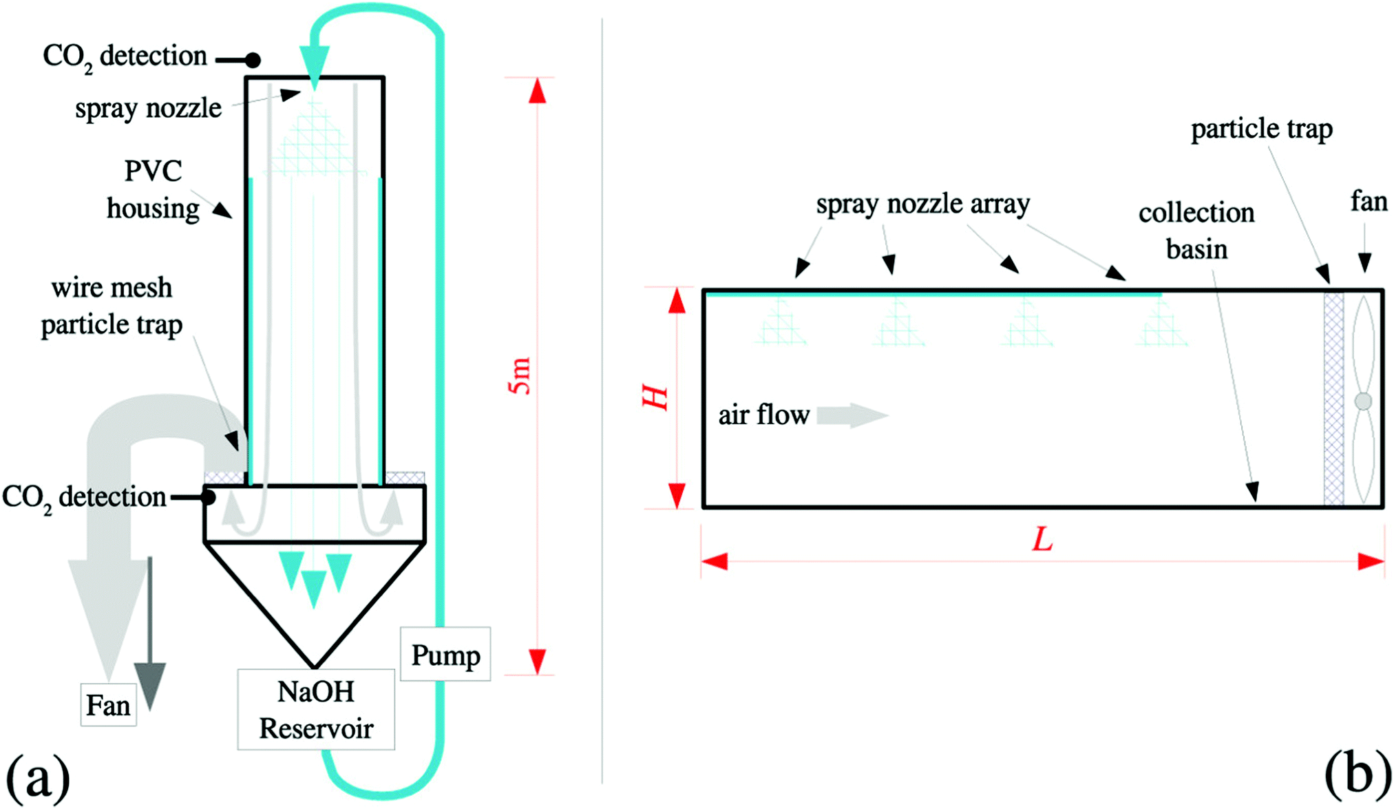 | ||
| Fig. 23 Representation of off-the-shelf spray contactor for DAC. Taken from ref. 356. Reprinted (adapted) with permission from Stolaroff et al., Carbon dioxide capture from atmospheric air using sodium hydroxide spray, Environ. Sci. Technol., 42, 2728–2735. Copyright 2008 American Chemical Society. | ||
Fasihi et al. has performed a comprehensive economic assessment and comparison of the near-commercial DAC plants.358 In contrast to the study by Stolaroff et al.,356 they considered the full DAC plant, including the air contactor and sorbent regeneration steps. For HT-DAC systems, Fasihi et al.358 considered the process design developed by Carbon Engineering (Fig. 3). Their model assumed that CO2 was removed in a continuous process, comprising air contactor, causticizer, slaker and calciner. Potassium hydroxide (KOH) was used as a solvent for CO2 capture and Ca(OH)2 for caustic solvent recovery. They also assumed that the energy demand for calcination is met with electricity, at 5.5 GJ per tCO2. Their economic assessment of HT-DAC, which assumed the weighted average cost of capital of 7% (capital charge of 9.4% at 20 years lifetime), indicated that a first-of-a-kind plant would result in the cost of CO2 removal of 815 € per tCO2 in 2020. As the technology matures, the costs were forecasted to reduce to 211–378 € per tCO2 in 2030, 122–265 € per tCO2 in 2040 and 93–222 € per tCO2 in 2050, assuming a conservative learning rate of 10–15%. Note that the original work presents a 94–233 $ per tCO2 value.167 Similarly to work by Stolaroff et al.,356 Fasihi et al. assumed overnight investment and did not account for the cost variation throughout the process lifetime.358
Zeman considered HT-DAC based on Ca(OH)2 as sorbent.359 Such an approach is deemed to avoid the challenges with sintering in conventional CaL cycles.360 Their work estimated that the amount of heat required to sustain the reaction in the calciner via oxy-fuel combustion is 6.7 GJ per tCO2 and the electrical energy requirement of 1.7 GJ per tCO2. It also estimated the cost of CO2 avoided would be 580 $ per tCO2. Yet, this figure was obtained based on the assumption that the electricity is supplied from the unabated natural gas combined cycle (NGCC) that emits 610 kgCO2 per MW h and supplies electricity at 71 $ per MW h. As such an approach is not sustainable, Zeman359 considered the electricity supplied from a NGCC with post-combustion CCS (107 $ per MW h, 43 kgCO2 per MW h) and a coal-fired power plant with post-combustion CCS (139 $ per MW h, 121 kgCO2 per MW h). Despite the increase in the unit cost of electricity associated with CCS, the overall cost of CO2 avoided reduced to 437 $ per tCO2 and 470 $ per tCO2. Importantly, a significant reduction in the cost of CO2 avoided was obtained on heat integration (3% reduction) and use of a plastic packing rather than a stainless-steel packing in the contactor (30% reduction). Nevertheless, such an approach to DAC relies on fossil fuels and may not be seen as sustainable in the long term. Moreover, the validity of their cost estimates needs to be verified, as a limited amount of information on the assumptions used in the economic assessment was provided.
Hanak et al. assessed the techno-economic performance of producing natural solid sorbents using an integrated calciner and solid-oxide fuel cell for DAC.268,308 In contrast to previous designs, this study assumed that the process is a once-through system and the produced metal oxides (CaO, MgO) will be spread in the open environment for CO2 removal from the air. In this way, the costs associated with a contactor were avoided. Moreover, this study used the net present value approach to economic assessment, considering the lifetime costs of DAC. The net present value was performed at 8.8% discount rate over the period of 25 years, yielding the capital charge of 10%. This study showed that the cost of CO2 removal would be 149 £ per tCO2 for limestone, 129.1–150.5 £ per tCO2 for dolomite and 368.8 £ per tCO2 for magnesite. Importantly, if the net amount of electricity produced in the SOFC was sold to the grid at 50 £ per MW h, the cost of CO2 removal reduced to 41.2 £ per tCO2 for limestone, 39.2–74.9 £ per tCO2 for dolomite and 312.1 £ per tCO2 for magnesite.
It needs to be emphasised that the HT-DAC designs presented above still relied on the use of fossil fuels for sorbent regeneration in the calciner. Sabatino et al. considered an alternative route for KOH-based solvent regeneration.207 Rather than using the calcium-based Kraft process, which is used in the Carbon Engineering design, they considered bipolar membrane electrodialysis (Fig. 4). In this process, CO2 is liberated from the solvent via ion transport through the membrane. This process is driven by the difference in electric potential across the membrane cells. Sabatino et al. used the levelized approach to estimate the CO2 removal cost, assuming the capital charge of 12.5%.207 Their study showed that the use of bipolar membrane electrodialysis could reduce total capital cost by about 27%. Moreover, the energy requirement for regeneration was reduced from 7.7 GJ per tCO2 to 5.4 GJ per tCO2 compared to the process used by Carbon Engineering. However, for the same system scale, the CO2 capture cost for the bipolar membrane electrodialysis was reported to be 773 $ per tCO2, compared to 232 $ per tCO2 reported for the Carbon Engineering design. This is mostly associated with the high cost of energy used to drive the electrodialysis process and the need for regular membrane replacement.
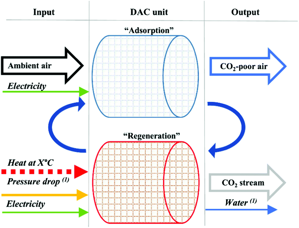 | ||
| Fig. 24 Representation of low-temperature DAC by Global Thermostat and Climeworks. Taken from Techno-economic assessment of CO2 direct air capture plants, ref. 358, license under CC BY 4.0. | ||
Sinha et al. evaluated the economic viability of MOFs for DAC via the temperature vacuum swing cycle (TVSC).284 The considered process assumes that CO2 adsorption takes place on monolith structures coated with MOF films (60 μm). Their study considered two of the most promising MOFs, MIL-101(Cr)-PEI-800 and mmen-Mg2(dobpdc). The considered process comprised of 5 cycles (Fig. 25), including adsorption, channel evacuation, channel pressurisation to atmospheric pressure, desorption, and cooling. The adsorption takes place at 298 K and 1 atm, whereas the desorption takes place at 373 K and 1 atm. The heat for desorption is supplied with saturated steam at 65 bar and 408 K that is produced using fossil energy. Their study showed that these sorbents would require a minimum of 3.3 GJ per tCO2 and 2.6 GJ per tCO2 of primary fossil energy.†† With the maximum energy use that would result in negative CO2 emissions of 10.2 GJ per tCO2, the CO2 emitted from fossil fuel combustion would be lower than that removed from the air, resulting in net negative CO2 removals.†† However, it needs to be stressed that the CO2 separation from the fossil fuel combustion is exponentially less energy intensive and should be, therefore, prioritised. Also, reliance on fossil fuels to drive DAC does not support its primary goal, which is to remove CO2 from the air. The high-level economic assessment performed by Shina et al. assumed the equipment lifetime of 10 years and the sorbent lifetime of 1–3 years.284 They have not provided details and assumptions behind the method used to perform the economic analysis. Their work showed that the TVSC DAC using MOFs should result in the cost of CO2 removal of 75–140 $ per tCO2 for MIL-101(Cr)-PEI-800 and 60–190 $ per tCO2 for mmen-Mg2(dobpdc). Although such performance would make DAC an attractive option for CDR, it is difficult to assess the accuracy and uncertainty behind these estimates.
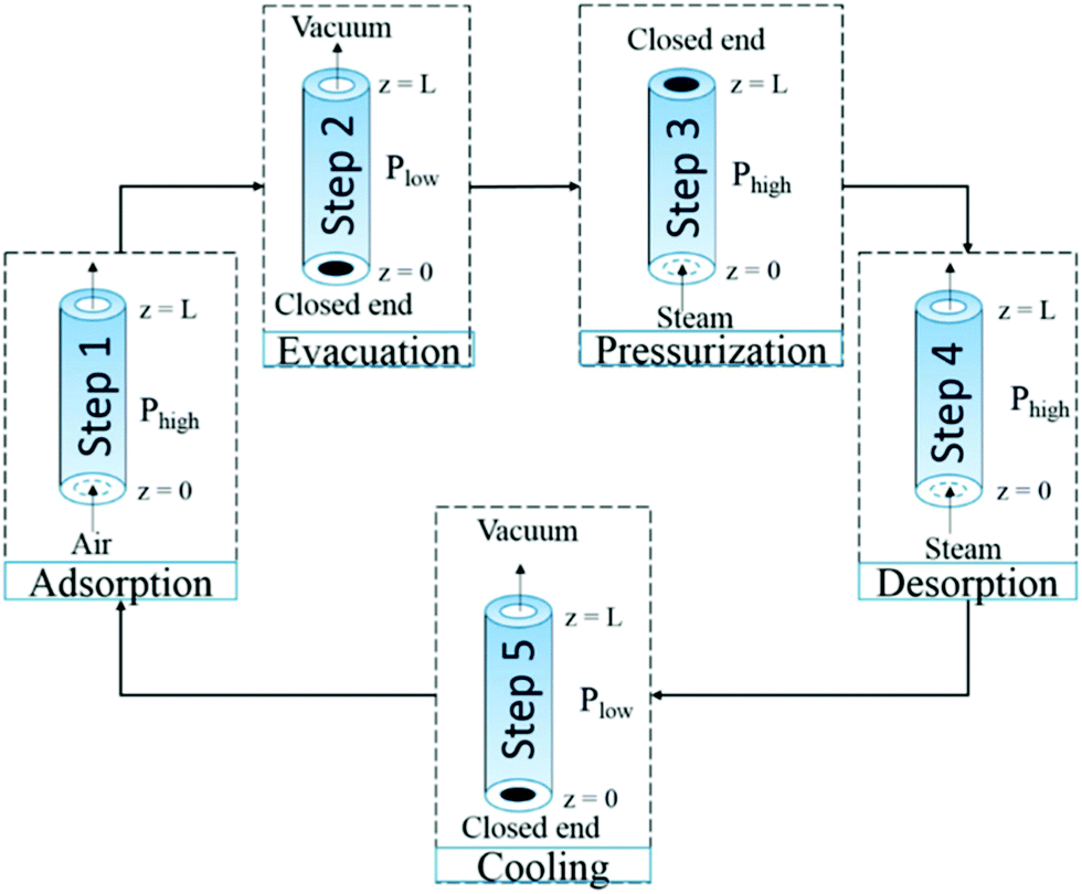 | ||
| Fig. 25 Temperature vacuum swing adsorption for DAC. Taken from ref. 284. Reprinted (adapted) with permission from Sinha et al., Systems design and economic analysis of direct air capture of CO2 through temperature vacuum swing adsorption using MIL-101(Cr)-PEI-800 and mmen-Mg2(dobpdc) MOF adsorbents, Ind. Eng. Chem. Res., 56, 750–764. Copyright 2017 American Chemical Society. | ||
Arazabadi and Lackner were the first to develop the comprehensive net present value (NPV) model for economic assessment of the sorbent-based DAC systems.361 Their approach to economics accounted for the degradation of the sorbent capacity with number of cycles. Their cost calculations assumed that the operation lifetime of the DAC device was equal to one lifetime of the sorbent, and that its scrap value was equal to the initial purchase price. Their model was set up to optimise the sorbent performance with the DAC performance, correlating the price of sorbent with the cost of CO2 removal. They applied their model to assess the DAC system based on temperature vacuum swing adsorption and using MOF-based sorbents (MIL-101(Cr)-PEI-800 and mmen-Mg2(dobpdc)) that were initially evaluated by Sinha.284 Assuming the discount rate of 5%, their work showed that under particular conditions, MOF-based sorbents could result in the cost of CO2 removal lower than 100 $ per tCO2. Namely, for MIL-101(Cr)-PEI-800 (sorbent cost 15 $ per kg), the minimum cost of CO2 removal was shown to be 75 $ per tCO2, with a cycle time of 22–39 min. For the mmen-Mg2(dobpdc) (sorbent cost 50 $ per kg), the minimum cost of CO2 capture would be 82 $ per tCO2 with a cycle time of 79 min. Such performance confirms the figures estimated by Sinha,284 and further demonstrate that LT-DAC can be more cost effective than HT-DAC.
Finally McQueen et al.362 considered LT-DAC that used a monolith contactor with functionalised solid-sorbent. Similarly to Sinha et al.,284 they considered a 5-step TVSC process, but their economic assessment focused on understanding how different sources of waste heat can influence DAC viability. Their study showed that the cost of CO2 capture varied between 205 $ per tCO2, 223 $ per tCO2 and 233 $ per tCO2 for the system driven by geothermal, natural gas, and nuclear plant, respectively. Despite similar costs, the geothermal and nuclear cases resulted in a significantly lower carbon footprint of the process, reducing the carbon intensity from 0.65 tCO2,emitted/tCO2,captured to 0.29 tCO2,emitted/tCO2,captured. This implies that for DAC systems to truly fulfil their design intent, these need to be driven via low-carbon energy sources.
4.2. Life-cycle analysis
Despite being considered as one of the technologies that will need to be deployed to maintain the atmospheric CO2 concentration in line with the agreed environmental targets, the assessment of the life-cycle GHG emissions is still limited in the current literature. The life-cycle performance of DAC is often considered as a part of the power-to-gas system,363–365 rather than as a standalone process. de Jonge et al.366 were the first to assess the environmental LCA of a DAC process. Their study considered HT-DAC using NaOH as a solvent, based on the Carbon Engineering design including an oxy-fired kiln. Their functional unit was 1 Mt CO2 removed from the air per year. Yet, the methodology used for the LCA study was not specified in detail. Their study showed that the majority of the life-cycle GHG emissions for the considered DAC process stem from the heat and electricity demand. The life-cycle carbon efficiency was shown to be 62% under the baseline case that considered natural gas as a source of energy for DAC. This means that for each Mt of CO2 removed from the air, 0.38 Mt of CO2 is emitted from natural gas combustion in the kiln. This can be improved to 92% if renewable energy and heat recovery are used to drive DAC. It is worth mentioning that if DAC is driven via a coal-fired power plant, the life-cycle carbon efficiency will reduce to 10%. This implies that the DAC would still be carbon negative, even though such a solution would not be sustainable as it would drive further use of fossil fuels.Deutz and Bardow assessed the LCA performance of the LT-DAC based on the Climeworks design.299 Their work considered a range of solid sorbents, including amines supported on oxides, alkali carbonates, and anionic resins. Their LCA approach relied on the ISO14040/14044 standards and considered the end use of CO2. The environmental impacts were assessed considering the Environmental Footprint 2.0 as the life-cycle impact assessment method. Their functional unit was “1 kg CO2 captured”. Their study revealed that LT-DAC using an amine-based adsorbent could achieve negative emissions, with the life-cycle carbon efficiency higher than 95% for the process driven via waste heat or low-carbon electricity. Importantly, a direct relationship between the carbon footprint of an electricity source and the carbon footprint of the DAC was derived (Fig. 26). Importantly, their work emphasised that CO2 from DAC can produce almost carbon-neutral fuels over the entire life cycle but requires low-carbon electricity. A comparison of several promising adsorbents indicated that there was no preferred option when all environmental impact categories were considered. For example, amine on alumina sorbent may appear to be the most optimum sorbent from the LCA perspective, but alumina manufacturing will cause higher human toxicity. Similarly, carbonate-based adsorbents had similar average LCA performance but resulted in enhanced eutrophication of freshwater due to K2CO3 production. This emphasises the importance of considering the LCA performance at the DAC design stage.
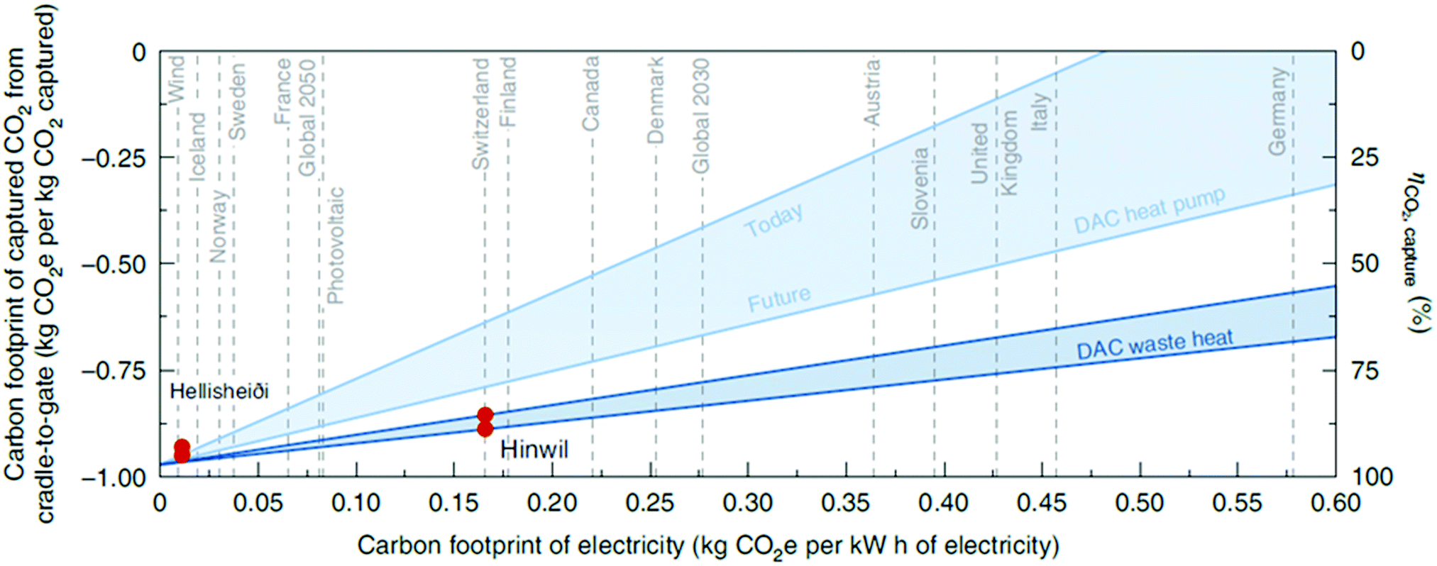 | ||
| Fig. 26 Effect of carbon footprint of electricity supply on carbon footprint of low-temperature DAC. Taken from ref. 299. Reprinted by permission from Springer Nature Customer Service Centre GmbH: [Springer Nature] [Nature Energy] [Life-cycle assessment of an industrial direct air capture process based on temperature-vacuum swing adsorption, Sarah Deutz & André Bardow], Copyright 2021. | ||
Finally, Terlouw et al.171 presented the first comprehensive assessment of the life-cycle emissions of DAC driven by low-carbon energy sources (Fig. 27). Their study, for the first time, considered the emissions associated with the carbon storage stage. Their LCA approach relied on the ISO 14040 standard and considered the ILCD 2.0 (2018) methodology to represent climate change, ecosystem quality, human health, and resources impact categories, and the ReCiPe (2016) methodology was used to assess the water depletion impact category. Their functional unit was “gross removal of 1 ton CO2 from the atmosphere via the use of a DAC plant combined with geological CO2 storage”. The DAC plant was represented based on the Climeworks technology (LT-DAC). Their study showed that for DAC to achieve life-cycle carbon efficiencies of >90%, the electricity and heat should be of low-carbon origin (Fig. 28). This can be the case for countries like Iceland or Norway, whose electricity grids are already highly decarbonised. High life-cycle carbon efficiencies of >85% are achievable worldwide for autonomous systems driven by solar PVs. For grids relying mostly on fossil fuels, such as in the case of Greece or Mexico, the use of grid electricity and heat pumps to drive DAC would yield life-cycle carbon efficiencies of only 9% and 17%, respectively. Although DAC in these countries will still result in net negative emissions, the cost of net CO2 removal will be significantly higher than that reported in previous sections. This implies that for DAC to be viable from environmental and economic standpoints, the electricity supply must be first fully decarbonised.
 | ||
| Fig. 27 Superstructure of the process boundaries for life-cycle emissions of DAC. Taken from ref. 171. Reprinted (adapted) with permission from Terlouw et al., Life cycle assessment of direct air carbon capture and storage with low-carbon energy sources, Environ. Sci. Technol., 55, 11397–11411. Copyright 2021 American Chemical Society. | ||
 | ||
| Fig. 28 Carbon removal efficiencies (%) and life-cycle greenhouse gas emissions for various DAC systems in different locations. Taken from ref. 171. Reprinted (adapted) with permission from Terlouw et al., Life cycle assessment of direct air carbon capture and storage with low-carbon energy sources, Environ. Sci. Technol., 55, 11397–11411. Copyright 2021 American Chemical Society. | ||
4.3. Comments on feasibility assessments of direct air capture
To date, only a handful of comprehensive TEAs and LCAs were performed to quantify the economic and environmental viability of DAC. More importantly, the data presented in the current literature show a large discrepancy in the economic viability of DAC. This is mostly because of the lack of standardised method, set of assumptions and benchmarks for DAC. The TEAs reviewed use different discount rates and project lifetimes, as well as methods, to estimate the cost of CO2 captured (or avoided), making a direct comparison of different DAC options challenging. Most figures reported do not account for the variation in operating cost associated with DAC, for example due to inflation or energy cost changes, over its lifetime. Although the LCA has been standardised and ISO14040/14044 standards were considered, the studies that assessed the life-cycle carbon efficiency of DAC used different approaches to life-cycle inventory analysis.5 Social implications of direct air capture systems and policy
5.1. Stakeholder concerns over development and deployment of direct air capture at scale
Unlike more widely discussed CDR options such as BECCS and AR, many key stakeholders have yet to develop a coherent position towards DAC. To the extent that stakeholders have devoted attention to this still-nascent technology, the prisms they have deployed have been economic, technological, risk-based, and moral.For many national governments and private actors who have taken an interest, the chief concern is cost. The costs associated with DAC infrastructure, energy generation, transport, storage, monitoring and maintenance,367,368 renders DAC significantly more expensive than other leading CDR and mitigation options.30,369 Although economies of scale are expected with upscaling, at present, the limited number of large-scale demonstrations and uncertainties in cost estimates pose strong disincentives for potential investors.367,370
Although some industry-leading firms have taken an interest in DAC to meet internal commitments, market demand is unlikely to cover longer-term deployment costs,371 given the large gap between DAC costs and other options. Moreover, private actors are generally reluctant to provide the required investment without public intervention.372 Yet governments are also hesitant because, in addition to the high cost, they do not want to appear to be picking winners.31
Moreover, the rollout of relevant components or analogous technologies such as CCS,373 and BECCS,374 has been stymied by numerous cases of public opposition, failures and aborted projects, which casts doubts over the credibility of DAC projects.375 On the other hand, countries with ample renewable and CO2 storage capacity may look more positively on DAC because they can take advantage of relevant technical knowledge and infrastructure investments. Given the massive energy and heat demands, both the potential technology pairings and the resulting geopolitics are important considerations for locating DAC plants. Iceland, with ample hydro and geothermal resources was identified by Climeworks for its Orca project. Similarly, EDF Energy recently secured funding to explore using low-carbon heat for DAC from its future nuclear power station at Sizewell C.376
Proponents of DAC tend to emphasize two main options for addressing cost concerns. First, a major claimed advantage of DAC over the other CCS-based CDR option (BECCS) is that it can be deployed proximate to storage and renewable energy facilities, significantly reducing transport costs.166,377,378 As discussed below, public attitudes towards CCS show that concern about the local effects of CO2 storage (such as leakage and seismic activity) as well as the pipelines needed to take the CO2 from the source to the storage site can sometimes obstruct projects from being deployed.379 Some contend that the ability to situate DAC away from host communities (e.g., offshore or in remote locations) could prove to be a key advantage in securing social license to operate,380,381 although, as with CCS more broadly, not all countries would have access to such sites and storage capacity would likely become scarce with upscaling.367,382
Another incentive for potential investors is the possibility of using or utilising the captured CO2 in commercially viable end use industries such as carbonated drinks, synthetic fuels and, most prominently, EOR.
Two key industries have demonstrated a keen interest in CCS: Energy and utility companies have focused on the possibility of combining DAC with existing energy facilities, notably with the oil and gas industry seeking to employ captured CO2 for EOR. Stakeholders in transport and aviation have also engaged with CCU options for producing low-carbon synthetic fuels for air and road transport,377,378,383 yet there is a fundamental risk that re-releasing the captured CO2 through utilisation will result in net increases rather than reductions.384,385 While a small number of existing DAC deployments involve long-term storage such as, for example, the United Airlines 1Point5 Project,386 or utilise the captured CO2 in permanent end-products such as building materials,387 most leading commercial DAC start-ups such as Carbon Engineering and Global Thermostat, supported by the venture arms of firms such as Occidental Petroleum and ExxonMobil, focus on EOR or other forms of CO2 utilisation and, therefore, do not qualify as genuine NETs. While CCU can only play a limited role in mitigation efforts (perhaps 0.5% of the mitigation challenge by 2050),385 the association between DAC and fossil fuel industries seems to validate environmentalist concerns that large-scale deployment could obstruct mitigation and ‘lock-in’ fossil fuel energy.388–390 Some describe DAC as a “societally uncontentious long-term prospect, but only if the relatively high energy demand is met by electricity from renewable sources”.391,392
As long as DAC projects continue to prioritise CCU over permanent storage, moral hazard concerns, that CDR could detract from mitigation,393,394 are likely to become harder to dispel and increase negative perceptions among commercial stakeholders and publics. Indeed, one study even quantified “a risk of assuming that DACCS can be deployed at scale” contributing to additional warming of up to 0.8°C if DAC was later found unavailable.166 A related concern is that DAC is premised on accepting the inevitability of overshoot and in so doing predestines such an outcome.392
Another attraction is DAC's potential to avoid some of the critical resource pressures and side-effects (e.g., ecosystem damage and rising food prices) associated with other leading NETs. Land requirements are expected to be several orders of magnitude smaller than that of other CDR options.26,166,371,377,395 Yet recent research suggests that this resource advantage may not be as large as earlier studies estimate. For example, while DAC requires much less land than BECCS and AR, accounting for water loss from evapotranspiration of unirrigated bioenergy crop cultivation,54 and water-rebound effects,382 suggests that water use is likely to be comparable to land-based NETs at scale. In addition, as noted, climatically-relevant deployment would eventually encounter limitations as suitable storage sites (such as deep saline formations, depleted hydrocarbon fields and coal fields) become scarce,367 and DAC's huge energy needs begin to encroach on energy security.382,396
Finally, DAC is often appealing to those otherwise less inclined towards more traditional mitigation options. In countries more polarised on climate change, such as the United States, DAC commands wider bipartisan support.397 Of course, such support also creates suspicions of DAC among proponents of aggressive climate action.
5.2. Wider public views of direct air capture and analogous mitigation options
How to allay concerns that DAC is nothing more than a “energetically and financially costly distraction”? 398 While public awareness of CDR is generally low, the handful of attempts to engage publics such as through citizens juries,399 and deliberative workshops,374,400–402 suggest that, when provided with sufficient time and resources, lay people tend to formulate thoughtful, sophisticated judgements about DAC and other CDR options. The few studies focused on DAC directly have found that public opinion is largely negative and mirrors many concerns raised by environmental NGOs.379,400 While some opposition is rooted in a general preference for mitigation over CDR, some of the aversion stems from perceptions of DAC as a negative futuristic solution in contrast to more familiar CDR options such as AR and SCS.400 At scale, there are likely to be further challenges as questions about the compatibility of DAC with other priorities such as energy security,31,396 and several UN SDGs,382 become more pertinent.Given low levels of public awareness, experience with more developed analogue technologies offers important insights for DAC.367,375,400 Research on CCS, for example, suggests that publics are often concerned about storage risks – both for potentially compromising mitigation outcomes and potential risks to local ecosystems, environments and human health.31,403,404 To the extent storage concerns are rooted in ‘Not in my back yard’ (NIMBY)-ism rather than moral hazard concerns, offshore storage might be preferable since support for CCS rises when the CO2 is stored off rather than onshore.380,403,404 There is also evidence of a ‘Yes in my back yard’ (YIMBY) effect whereby host communities are more supportive of CCS than the wider public due to the anticipation of local economic benefits,405 suggesting that DAC might be more popular when it is associated with job creation and infrastructural investment.406 Relatedly, attitudes towards DAC may be influenced by whether the captured CO2 is utilised in another industry and, therefore, linked to greater revenue streams than storage.407,408 Publics may be more supportive if DAC is incentivised by a socially acceptable policy instrument, although what that instrument is will vary by country.100,409,410
Analogous deployment experiences suggest potential strategies that could help address public concerns are likely to arise as DAC is upscaled. One obvious strategy emerging from previous CCS projects is to include local interests in the decision-making process, which has been found to pre-empt major opposition by addressing potential adverse effects (e.g., storage risks and energy pressures) and identifying benefits (e.g., employment, training opportunities and infrastructure investment).379,411 Second, placing stronger emphasis on the relative advantages of DAC (e.g., storage permanence, location-independence and spatial footprint) could help construe the technology as a key option for delivering significant negative emissions rather than a means for facilitating the continuation of fossil fuel extraction.166,371,412 More broadly, all NETs are likely to elicit higher support if presented as transitional measures complementary to, rather than in conflict with, mitigation, just energy transitions and other CDR options.382,413
5.3. Existing and proposed policies to incentivize the development and deployment of direct air capture
The sources of funding have also drawn scrutiny. Many early start-ups had to rely on funding from private sources including, notably, the oil and gas industry.180,182,189 As its potential importance to climate action has risen, there have been calls for more public funding (e.g., US National Academies).116 Governments have begun to make significant initial investments such as the UK Government £100 million programme for DAC and other GHG removal technologies.414 The UK Net Zero Investment Portfolio has also received match funding from the Breakthrough Energy Catalyst led by Bill Gates for a public–private partnership to support innovation (including DAC).415 Governments have also created ambitious targets – for example, the US government recently launched a ‘Carbon Negative Shot’ to make CDR (including DAC) available for <100 $ per ton by 2050.416To date, only a handful of governments (led by the US and UK) have committed funding for DAC. Most existing policy incentives are available through schemes that support CDR or CCS more broadly rather than DAC specifically.417,418 Several national governments have introduced schemes to incentivise CO2 storage, such as the 45Q tax credit in the US, whereas in other countries such as Norway or the UK the focus has shifted to support for transport and storage infrastructure.419,420 A few jurisdictions have adopted criteria for low-carbon fuels, such as, for example, the European Renewable Energy Directive and California's Low Carbon Fuel Standard, which could be expanded (e.g., by requiring fuel producers to comply with carbon-negative standards) to incorporate DAC.371 Although such initiatives would incentivise CCU applications, they could also stimulate learning and cost reductions in the early stages of development.31,371,377,396,421 However, a number of limitations remain. Fundamentally, CDR can be sourced at substantially lower costs from other sources such as CCS without DAC and other NETs.377,408,421 As discussed below, incentivising geological storage through various policy instruments such as storage-based accounting and setting permanent storage standards for key industries. Yet there are also other obstacles, such as restrictive eligibility criteria and revenue streams for CCU (especially EOR) that currently make non-CDR applications more appealing.
As DAC emerges from the R&D phase, governments will have different policy levers at their disposal for incentivizing DAC and driving down costs. Technology mandates could ensure DAC is deployed in key industries such as energy and transport, although such mandates would need to be designed to avoid simply prolonging the use of old, high-carbon plants.30,371,422 Tax breaks and capital grants have played a key role in supporting other low-carbon technologies such as offshore wind and solar PV, providing another option for mitigating the risks associated with large-scale DAC demonstrations.423,424 In addition, government procurement of DAC-based applications such as low-carbon fuels or construction materials could stimulate demand for DAC.421
Most forecasts involving large-scale CDR assume a much higher carbon price to internalize the effects of CO2 on the climate system. Taxing carbon emissions could effectively become a subsidy for negative emissions, which, at climatically relevant scale, would require massive expenditures (as much as a third of general government spending in advanced economies).372 Political reactions to taxes and subsidies for renewables suggest that relying on carbon taxes or negative emission subsidies will become increasingly challenging as DAC grows.371 Moreover, carbon pricing alone would not induce the needed global transition away from fossil fuels and optimal CDR deployment as both outcomes are likely to require different prices.370
The fundamental issue facing all of these policy options is that, currently, carbon pricing does not reward CDR, which renders alternative decarbonization options significantly cheaper than NETs in general and DAC in particular.408 Several experts propose that accounting based on storage, rather than emissions, could provide the necessary incentives for upscaling CDR applications of CCS-based technologies.382,407,408,410 Daggash and MacDowell, for example, propose a negative emissions credit – payment for each ton of CO2 removed, which would also reduce overall end-prices.408 Similarly, Jenkins et al. propose the concept of a ‘carbon takeback obligation’ (CTO) to shift accounting away from the polluter pays principle, which is based on counting emissions, to producer storage, which involves counting storage.407 In order to be effective, such proposals would need to be accompanied by comprehensive regulatory mechanisms for managing risks, long-term storage and verification spanning up and downstream flows, and be integrated with complementary frameworks for overseeing interactions with other priorities such as food supply, energy security and sustainable development.400,425
5.4. Social implications of scaling up
As DAC plants have moved from the drawing board to larger demonstration plants, the technologies (and respective start-ups) have attracted greater media attention and interest by firms as customers, as well as greater scrutiny for the wider systemic role it might play. For example, large firms such as Shopify, Audi, Microsoft and Swiss Re have become customers for Orca, the largest DACCS project launched by Climeworks and Carbfix, which will remove 4000 tons of CO2 per year.426 Carbon Engineering is planning a megaton scale plant in West Texas (that will also be used for EOR) by 2024 and a second facility in Scotland by 2026.427Public interest has also increased as a result. For example, as measured by Google Trends, after first appearing in 2010, searches for ‘direct air capture’ were only intermittent until 2017 when there began to be a steadier, if low-level, interest and by 2019 searches began to increase substantially. Attention shot up even more dramatically in 2021 (Fig. 29).428
 | ||
| Fig. 29 Google Trends data on worldwide searches for search term “Direct air capture” from January 2004 to September 2021. Each data point is generated by dividing the number of searches by the total searches in the same geography and time. This ratio is then normalised so that peak popularity is equal to 100. | ||
Ultimately, the social viability of any policy instrument depends on a nation's political economy, social values, norms and priorities.409 The history of energy transitions shows that low-carbon energy technologies tend to be more successful in eliciting public support when opportunities are provided for stakeholders to voice concerns about potential side-effects and risks and influence the creation of local incentives.410,429 Distributing responsibility for upscaling DAC and other CDR options will inevitably be politically contentious and require attention at both the national and international level to questions of equity.430,431 Most cost-optimal pathways to net-zero are based on deploying BECCS and AR at scale in countries where the potential for negative emissions is highest.11,432 Yet even if international assistance (e.g., technology transfers and funds) is available to help with deployment, this would effectively mean that ideally-situated host countries, which might have minimal responsibility for historical emissions, would bear most of the burden for dealing with the adverse consequences of CDR such as integrating new energy flows with existing (often fragile) infrastructure, substantial land use changes and displacement.374,410,429,433 The ability of DAC to facilitate location-independent sourcing of CO2 could thus prove critical for enabling advanced economies with geological storage capacity and greater willingness to shoulder more of the burden by hosting NET projects with permanent storage outcomes.371
6 Conclusions
We have reviewed the state-of-the-art in DAC across the commercial and research sectors, seeking to provide clear research challenges in the science, engineering, economics, and socio-political domains. The development and deployment of DAC will continue to provide research challenges as the technology has to date been developed by a limited number of start-ups. This has resulted in a somewhat narrow focus; in the first decade or so after DAC was proposed, almost all research focussed on developing sorbents and a limited number of process configurations. Whilst continued improvement of these materials and processes is warranted, particularly in understanding their integration with the energy system, their evolving costs, and their sustainability from a wider frame of reference, a focus on new materials and processes for DAC will provide new opportunities, and the development of DAC will raise challenges in the socio-political domain also. To conclude, we discuss high-level challenges that researchers could address soon to improve our understanding of DAC, unlock new levels of efficiency and sustainability, and increase societal acceptance.Climate change will require adaptation and mitigation on a massive scale (Section 1). This will involve changes to human practices and behaviours, structural and physical adaptation, a broad portfolio of clean energy generation technologies, as well as technologies to mitigate GHG emissions. The need for, and interaction between these aspects of adaptation and mitigation will evolve with time and thus efforts at understanding the complexity, inter-dependencies, pace, and scale involved will continue to be of the highest importance.
DAC (and other NETs) are not a substitute for e.g., improved energy efficiency, the development of a circular economy, conventional decarbonisation, and more sustainable practices (Section 2). However, DAC offers some unique advantages amongst various NETs and other CCS-related technologies. These advantages should be exploited, yet there is much more that can be done. For example, in almost all cases of DAC deployment, CO2 utilisation is a crucial technology enabler. However, it is also known that CO2 utilisation (as compared to storage) is sub-optimal in terms of climate change mitigation. Thus, DAC coupled with geological storage (i.e., DACCS) should be pursued as a deployment priority. Scenarios where CO2 utilisation is economically favourable should not serve as a distraction but may prove useful to demonstrate DAC technology in the near-term.
CCS processes are only beginning to be deployed at the scale required for meaningful climate change mitigation, whilst DAC is still very much in its infancy (Section 3). Increases in capture rates (i.e., beyond 90%) in CCS processes will reduce the burden on DAC and other NETs and is therefore a research and deployment priority. The most developed DAC processes rely on sorbents, either liquid or solid. For liquid sorbents, electrochemical regeneration methods appear to show promise for reducing energy requirements, if they can be demonstrated at a suitable scale, with sufficient reliability and reduced materials costs. New liquids with lower regeneration energy requirements will always be beneficial, and it is notable that there is a lack of work on liquid-air contacting. For solid sorbents, several challenges have emerged during deployment, as discussed above. These deserve attention to improve existing processes, as does the development of entirely new sorbents (and associated understanding of structure–activity relationships). However, in all cases, consideration should be given to manufacturing of sorbents at scale and it is also prudent to highlight the disparity between laboratory-scale investigations (sorbent regeneration practices, measurement of equilibrium sorption capacity etc.) and the realities involved with deployment. Entirely new DAC processes (i.e., those not relying on sorbents) may offer bespoke options for specific scenarios and, importantly, inspiration for entirely new ways to approach DAC. As DAC is a relatively new technology, investment in ‘blue skies research’ here is likely to provide significant return. Amongst those emerging technologies discussed, electrochemical devices show significant promise, yet they have scarcely been investigated. Passive DAC contacting and the design of physisorbents has taken inspiration from nature; it would seem foolish not to explore the nexus between natural and engineered DAC systems much further.
A limited amount of reliable data is presented in the literature on both techno-economic and life-cycle environmental performance of DAC (Section 4). To date, only a handful of comprehensive technology assessments have been published to accurately establish the economic and environmental viability of DAC. In the most optimistic scenarios, the long-term cost of CO2 removal was shown to vary between 40–80 € per tCO2 for low-temperature DAC and 45–90 € per tCO2 for high-temperature DAC. It needs to be stressed that there is a large discrepancy in the reported economic viability of DAC, and the cost of CDR up to 400–800 € per tCO2 that has been reported. Such discrepancies result from a lack of standardised assessment methods and reliable benchmarks for DAC. From the life-cycle emissions perspective, DAC was shown to achieve life-cycle carbon efficiencies of 85–95% when driven by low-carbon energy sources. However, if DAC is driven by electricity from grids relying on fossil fuels, the life-cycle efficiencies can be as low as 9–17%. This means that for each 1 kg of CO2 removed from the air, 0.83–0.91 kg of CO2 is released into the atmosphere from the combustion of fossil fuels, negating the true potential of DAC. Importantly, although the LCAs presented in the literature follow the standardised assessment procedures, different approaches to life-cycle inventory analysis and data sources were used. Consequently, past TEAs and LCAs rely on different sets of assumptions, making reliable benchmarking of reported results difficult, if not impossible. It is, therefore, important to derive a set of standardised guidelines and benchmarks that would enable a reliable comparison of DAC.
There are many policy challenges including how to finance demonstration projects and then scale up DAC technologies in the hopes of bringing costs down sufficiently to the point where it is a viable option even with respect to other NETs (Section 5). Most mechanisms have been developed in the more general context of supporting CDR and CO2 storage, but increasingly there have been more DAC-specific initiatives. There are many attractions of DAC including its greater flexibility in plant location and ability to address overshoot and scale up without some of the social and political constraints faced by other CDR and climate change mitigation options. On the other hand, the attention given to CCU and the association of several of the first major projects with the oil and gas industry, though valuable at providing financing at an early stage, has also led to concerns that DAC will detract from other mitigation options and ensure overshoot. Public and even stakeholder awareness has been low, but as the first large-scale projects have been deployed, DAC has begun to receive greater scrutiny. As interest in DAC has risen, some governments have begun to fund programmes to support early-stage DAC projects and set ambitious targets to bring down the costs of DAC.
Ultimately, DAC is in its infancy, with its place in the energy system and climate change mitigation efforts yet to be clearly defined. Regardless, the challenges associated with DAC forces us to redouble our efforts on climate change mitigation through more conventional efforts and, importantly, to continue to be creative in tackling apparently intractable problems.
Disclaimer
The content of this article does not reflect the official opinion of the European Union. Responsibility for the information and views expressed herein lies entirely with the author(s).Author contributions
All authors contributed individual sections during writing – original draft. All authors were involved in writing – review and editing. All authors were responsible for their respective funding acquisition, where applicable. GAM was responsible for overall project administration.Conflicts of interest
There are no conflicts to declare.Acknowledgements
This project has received funding from the European Union's Horizon 2020 research and innovation programme under the Marie-Skłodowska-Curie grant agreement No. 754382, GOT ENERGY TALENT. ESP is grateful for funding from the Young Researchers R&D Project Ref. M-2177-DESMAT financed by the Community of Madrid and the Rey Juan Carlos University. ZC and DMR are grateful for support from the Engineering & Physical Sciences Research Council (EPSRC) via grant EP/P026214/1 and the Natural Environment Research Council (NERC) via grant NE/P019900/1. GAM was supported by the Royal Academy of Engineering under the Research Fellowship scheme. GAM is also grateful for support from the EPSRC via grant EP/V047078/1 (SynHiSel) and the UK Catalysis Hub funded by EPSRC grant reference EP/R027129/1 (Hub ‘Science’ 3: Catalysis for the Circular Economy and Sustainable Manufacturing). I. Metcalfe, W. Hu and I. Ahmed of Newcastle University are thanked for helpful comments during the preparation of the manuscript.Notes and references
- V. Masson-Delmotte, P. Zhai, A. Pirani, S. L. Connors, C. Péan, S. Berger, N. Caud, Y. Chen, L. Goldfarb, M. I. Gomis, M. Huang, K. Leitzell, E. Lonnoy, J. B. R. Matthews, T. K. Maycock, T. Waterfield, O. Yelekçi, R. Yu and B. Zhou, IPCC, 2021: Climate Change 2021: The Physical Science Basis. Contribution of Working Group I to the Sixth Assessment Report of the Intergovernmental Panel on Climate Change, Cambridge University Press, 2021 Search PubMed.
- E. Dlugokencky and P. Tans, NOAA/GML (http://gml.noaa.gov/ccgg/trends).
- GISTEMP Team – Nasa Goddard Institute for Space Studies, https://data.giss.nasa.gov/gistemp/.
- J. B. Smith, S. H. Schneider, M. Oppenheimer, G. W. Yohe, W. Hare, M. D. Mastrandrea, A. Patwardhan, I. Burton, J. Corfee-Morlot, C. H. D. Magadza, H.-M. Füssel, A. B. Pittock, A. Rahman, A. Suarez and J.-P. van Ypersele, Proc. Natl. Acad. Sci. U. S. A., 2009, 106, 4133–4137 CrossRef CAS PubMed.
- R. E. Kopp, R. M. DeConto, D. A. Bader, C. C. Hay, R. M. Horton, S. Kulp, M. Oppenheimer, D. Pollard and B. H. Strauss, Earth's Future, 2017, 5, 1217–1233 CrossRef.
- K. K. Rigaud, A. de Sherbinin, B. Jones, J. Bergmann, V. Clement, K. Ober, J. Schewe, S. Adamo, B. McCusker, S. Heuser and A. Midgley, Groundswell: Preparing for Internal Climate Migration, World Bank, 2018 Search PubMed.
- P. Friedlingstein, M. O’Sullivan, M. W. Jones, R. M. Andrew, J. Hauck, A. Olsen, G. P. Peters, W. Peters, J. Pongratz, S. Sitch, C. Le Quéré, J. G. Canadell, P. Ciais, R. B. Jackson, S. Alin, L. E. O. C. Aragão, A. Arneth, V. Arora, N. R. Bates, M. Becker, A. Benoit-Cattin, H. C. Bittig, L. Bopp, S. Bultan, N. Chandra, F. Chevallier, L. P. Chini, W. Evans, L. Florentie, P. M. Forster, T. Gasser, M. Gehlen, D. Gilfillan, T. Gkritzalis, L. Gregor, N. Gruber, I. Harris, K. Hartung, V. Haverd, R. A. Houghton, T. Ilyina, A. K. Jain, E. Joetzjer, K. Kadono, E. Kato, V. Kitidis, J. I. Korsbakken, P. Landschützer, N. Lefèvre, A. Lenton, S. Lienert, Z. Liu, D. Lombardozzi, G. Marland, N. Metzl, D. R. Munro, J. E. M. S. Nabel, S. I. Nakaoka, Y. Niwa, K. O’Brien, T. Ono, P. I. Palmer, D. Pierrot, B. Poulter, L. Resplandy, E. Robertson, C. Rödenbeck, J. Schwinger, R. Séférian, I. Skjelvan, A. J. P. Smith, A. J. Sutton, T. Tanhua, P. P. Tans, H. Tian, B. Tilbrook, G. Van Der Werf, N. Vuichard, A. P. Walker, R. Wanninkhof, A. J. Watson, D. Willis, A. J. Wiltshire, W. Yuan, X. Yue and S. Zaehle, Earth Syst. Sci. Data, 2020, 12, 3269–3340 CrossRef.
- International Energy Agency, World Energy Outlook, 2021 Search PubMed.
- J. Olivier and J. Peters, Trends in Global CO2 and Total Greenhouse Gas Emissions; 2020 Report, PBL Netherlands Environmental Assessment Agency, 2020 Search PubMed.
- S. Henbest, M. Kimmel, J. Callens, A. Vasdev, T. Brandily, I. Berryman, J. Danial and B. Vickers, BloomberfNEF: New Energy Outlook 2021, 2021 Search PubMed.
- IPCC, 2018: Global Warming of 1.5 °C. An IPCC Special Report on the impacts of global warming of 1.5 °C above pre-industrial levels and related global greenhouse gas emission pathways, in the context of strengthening the global response to the threat of climate change, sustainable development, and efforts to eradicate poverty, ed. V. Masson-Delmotte, P. Zhai, H.-O. Portner, D. Roberts, J. Skea, P. R. Shukla, A. Pirani, W. Moufouma-Okia, C. Pean, R. Pidcock, S. Connors, J. B. R. Matthews, Y. Chen, X. Zhou, M. I. Gomis, E. Lonnoy, T. Maycock, M. Tignor and T. Waterfield, Cambridge University Press, 2018 Search PubMed.
- International Renewable Energy Agency, World Energy Transitions Outlook: 1.5 °C Pathway, 2021 Search PubMed.
- British Petroleum, Energy Outlook, 2020 Search PubMed.
- L. T. Keyßer and M. Lenzen, Nat. Commun., 2021, 12, 2676 CrossRef PubMed.
- Lazard, Levelized Cost of Energy Analysis, 2020.
- IRENA, Renewable Capacity Statistics 2021, 2021 Search PubMed.
- BP, Statistical Review of World Energy, 2021 Search PubMed.
- M. E. Mann, The New Climate War: The Fight to Take Back Our Planet, Scribe UK, 2021 Search PubMed.
- G. P. Peters, Nat. Clim. Change, 2016, 6, 646–649 CrossRef.
- J. Rogelj, A. Popp, K. V. Calvin, G. Luderer, J. Emmerling, D. Gernaat, S. Fujimori, J. Strefler, T. Hasegawa, G. Marangoni, V. Krey, E. Kriegler, K. Riahi, D. P. Van Vuuren, J. Doelman, L. Drouet, J. Edmonds, O. Fricko, M. Harmsen, P. Havlík, F. Humpenöder, E. Stehfest and M. Tavoni, Nat. Clim. Change, 2018, 8, 325–332 CrossRef CAS.
- J. Rogelj, G. Luderer, R. C. Pietzcker, E. Kriegler, M. Schaeffer, V. Krey and K. Riahi, Nat. Clim. Change, 2015, 5, 519–527 CrossRef.
- G. Luderer, R. C. Pietzcker, C. Bertram, E. Kriegler, M. Meinshausen and O. Edenhofer, Environ. Res. Lett., 2013, 8, 034033 CrossRef.
- J. C. Minx, W. F. Lamb, M. W. Callaghan, L. Bornmann and S. Fuss, Environ. Res. Lett., 2017, 12, 035007 CrossRef.
- J. C. Minx, W. F. Lamb, M. W. Callaghan, S. Fuss, J. Hilaire, F. Creutzig, T. Amann, T. Beringer, W. De Oliveira Garcia, J. Hartmann, T. Khanna, D. Lenzi, G. Luderer, G. F. Nemet, J. Rogelj, P. Smith, J. L. Vicente Vicente, J. Wilcox and M. Del Mar Zamora Dominguez, Environ. Res. Lett., 2018, 13, 063001 CrossRef.
- S. Fuss, C. D. Jones, F. Kraxner, G. P. Peters, P. Smith, M. Tavoni, D. P. Van Vuuren, J. G. Canadell, R. B. Jackson, J. Milne, J. R. Moreira, N. Nakicenovic, A. Sharifi and Y. Yamagata, Environ. Res. Lett., 2016, 11, 115007 CrossRef.
- P. Smith, S. J. Davis, F. Creutzig, S. Fuss, J. Minx, B. Gabrielle, E. Kato, R. B. Jackson, A. Cowie, E. Kriegler, D. P. Van Vuuren, J. Rogelj, P. Ciais, J. Milne, J. G. Canadell, D. McCollum, G. Peters, R. Andrew, V. Krey, G. Shrestha, P. Friedlingstein, T. Gasser, A. Grübler, W. K. Heidug, M. Jonas, C. D. Jones, F. Kraxner, E. Littleton, J. Lowe, J. R. Moreira, N. Nakicenovic, M. Obersteiner, A. Patwardhan, M. Rogner, E. Rubin, A. Sharifi, A. Torvanger, Y. Yamagata, J. Edmonds and C. Yongsung, Nat. Clim. Change, 2016, 6, 42–50 CrossRef CAS.
- L. E. Clarke, K. Jiang, K. Akimoto, M. Babiker, G. J. Blanford, K. Fisher-Vanden, J.-C. Hourcade, V. Krey, E. Kriegler and A. Loschel, Assessing Transformation Pathways, Climate Change 2014: Mitigation of Climate Change. Contribution of Working Group III to the Fifth Assessment Report of the Intergovernmental Panel on Climate Change, Cambridge University Press, 2014 Search PubMed.
- J. Rogelj, D. Shindell, K. Jiang, S. Fifita, P. Forster, V. Ginzburg, C. Handa, H. Kheshgi, S. Kobayashi, E. Kriegler, L. Mundaca, R. Séférian and M. V. Vilariño, Mitigation Pathways Compatible with 1.5 °C in the Context of Sustainable Development, in Global Warming of 1.5 °C. An IPCC Special Report on the impacts of global warming of 1.5 °C above pre-industrial levels and related greenhouse gas emission pathways, in, Cambridge University Press, 2018 Search PubMed.
- J. C. M. Pires, Sci. Total Environ, 2019, 672, 502–514 CrossRef CAS PubMed.
- S. Fuss, W. F. Lamb, M. W. Callaghan, J. Hilaire, F. Creutzig, T. Amann, T. Beringer, W. De Oliveira Garcia, J. Hartmann, T. Khanna, G. Luderer, G. F. Nemet, J. Rogelj, P. Smith, J. V. Vicente, J. Wilcox, M. Del Mar Zamora Dominguez and J. C. Minx, Environ. Res. Lett., 2018, 13, 063002 CrossRef.
- G. F. Nemet, M. W. Callaghan, F. Creutzig, S. Fuss, J. Hartmann, J. Hilaire, W. F. Lamb, J. C. Minx, S. Rogers and P. Smith, Environ. Res. Lett., 2018, 13, 063003 CrossRef.
- G. J. Nabuurs, O. Masera, K. Andrasko, P. Benitez-Ponce, R. Boer, M. Dutschke, E. Elsiddig, J. Ford-Robertson, P. Frumhoff and T. Karjalainen, Forestry. In Climate Change 2007: Mitigation. Contribution of Working Group III to the Fourth Assessment Report of the Intergovernmental Panel on Climate Change, Cambridge University Press, 2007 Search PubMed.
- K. R. Richards and C. Stokes, Clim. Change, 2004, 63, 1–48 CrossRef.
- F. Humpenöder, A. Popp, J. P. Dietrich, D. Klein, H. Lotze-Campen, M. Bonsch, B. L. Bodirsky, I. Weindl, M. Stevanovic and C. Müller, Environ. Res. Lett., 2014, 9, 64029 CrossRef.
- R. T. Watson, M. C. Zinyowera and R. H. Moss, Climate Change 1995 – Impacts, adaptations and mitigation of climate change: Scientific-technical analyses, Cambridge University Press, 1996 Search PubMed.
- B. Sohngen and R. Mendelsohn, Am. J. Agric. Econ., 2003, 85, 448–457 CrossRef.
- T. M. Lenton, Geoeng. Clim. Syst., 2014, 662, 52–79 Search PubMed.
- R. G. Anderson, J. G. Canadell, J. T. Randerson, R. B. Jackson, B. A. Hungate, D. D. Baldocchi, G. A. Ban-Weiss, G. B. Bonan, K. Caldeira and L. Cao, Front. Ecol. Environ., 2011, 9, 174–182 CrossRef.
- V. K. Arora and A. Montenegro, Nat. Geosci., 2011, 4, 514–518 CrossRef CAS.
- R. A. Betts, P. D. Falloon, K. K. Goldewijk and N. Ramankutty, Agric. For. Meteorol., 2007, 142, 216–233 CrossRef.
- R. B. Jackson, J. T. Randerson, J. G. Canadell, R. G. Anderson, R. Avissar, D. D. Baldocchi, G. B. Bonan, K. Caldeira, N. S. Diffenbaugh and C. B. Field, Environ. Res. Lett., 2008, 3, 44006 CrossRef.
- Y. Wang, X. Yan and Z. Wang, Theor. Appl. Climatol., 2014, 118, 511–521 CrossRef.
- J. Ahirwal, S. Kumari, A. K. Singh, A. Kumar and S. K. Maiti, Ecol. Indic., 2021, 123, 107354 CrossRef CAS.
- J. M. Hall, T. Van Holt, A. E. Daniels, V. Balthazar and E. F. Lambin, Landsc. Ecol., 2012, 27, 1135–1147 CrossRef.
- D. C. McKinley, M. G. Ryan, R. A. Birdsey, C. P. Giardina, M. E. Harmon, L. S. Heath, R. A. Houghton, R. B. Jackson, J. F. Morrison and B. C. Murray, Ecol. Appl., 2011, 21, 1902–1924 CrossRef PubMed.
- B. Locatelli, C. P. Catterall, P. Imbach, C. Kumar, R. Lasco, E. Marín-Spiotta, B. Mercer, J. S. Powers, N. Schwartz and M. Uriarte, Restor. Ecol., 2015, 23, 337–343 CrossRef.
- S. Díaz, D. A. Wardle and A. Hector, in Biodiversity, Ecosystem Functioning, and Human Wellbeing, Oxford University Press, Oxford, UK, 2009, pp. 149–166 Search PubMed.
- P. Smith, R. S. Haszeldine and S. M. Smith, Environ. Sci. Process. Impacts, 2016, 18, 1400–1405 RSC.
- H. Li, C. Wang, F. Zhang, Y. He, P. Shi, X. Guo, J. Wang, L. Zhang, Y. Li, G. Cao and H. Zhou, Sci. Total Environ, 2021, 791, 148379 CrossRef CAS PubMed.
- R. Lal, Science, 2004, 304, 1623–1627 CrossRef CAS PubMed.
- G. Pan, P. Smith and W. Pan, Agric., Ecosyst. Environ., 2009, 129, 344–348 CrossRef.
- D. Nayak, E. Saetnan, K. Cheng, W. Wang, F. Koslowski, Y. F. Cheng, W. Y. Zhu, J. K. Wang, J. X. Liu, D. Moran, X. Yan, L. Cardenas, J. Newbold, G. Pan, Y. Lu and P. Smith, Agric., Ecosyst. Environ., 2015, 209, 108–124 CrossRef CAS.
- Y. Liao, W. L. Wu, F. Q. Meng, P. Smith and R. Lal, Biogeosciences, 2015, 12, 1403–1413 CrossRef.
- P. Smith, Glob. Change Biol., 2016, 22, 1315–1324 CrossRef PubMed.
- M. Jiang, B. E. Medlyn, J. E. Drake, R. A. Duursma, I. C. Anderson, C. V. M. Barton, M. M. Boer, Y. Carrillo, L. Castañeda-Gómez, L. Collins, K. Y. Crous, M. G. De Kauwe, B. M. dos Santos, K. M. Emmerson, S. L. Facey, A. N. Gherlenda, T. E. Gimeno, S. Hasegawa, S. N. Johnson, A. Kännaste, C. A. Macdonald, K. Mahmud, B. D. Moore, L. Nazaries, E. H. J. Neilson, U. N. Nielsen, Ü. Niinemets, N. J. Noh, R. Ochoa-Hueso, V. S. Pathare, E. Pendall, J. Pihlblad, J. Piñeiro, J. R. Powell, S. A. Power, P. B. Reich, A. A. Renchon, M. Riegler, R. Rinnan, P. D. Rymer, R. L. Salomón, B. K. Singh, B. Smith, M. G. Tjoelker, J. K. M. Walker, A. Wujeska-Klause, J. Yang, S. Zaehle and D. S. Ellsworth, Nature, 2020, 580, 227–231 CrossRef CAS PubMed.
- P. Smith, Glob. Change Biol., 2012, 18, 35–43 CrossRef.
- P. L. Stanley, J. E. Rowntree, D. K. Beede, M. S. DeLonge and M. W. Hamm, Agric. Syst., 2018, 162, 249–258 CrossRef.
- J. K. Green, S. I. Seneviratne, A. M. Berg, K. L. Findell, S. Hagemann, D. M. Lawrence and P. Gentine, Nature, 2019, 565, 476–479 CrossRef CAS PubMed.
- C. Kammann, J. Ippolito, N. Hagemann, N. Borchard, M. L. Cayuela, J. M. Estavillo, T. Fuertes-Mendizabal, S. Jeffery, J. Kern, J. Novak, D. Rasse, S. Saarnio, H. P. Schmidt, K. Spokas and N. Wrage-Mönnig, J. Environ. Eng. Landsc. Manage., 2017, 25, 114–139 CrossRef.
- X. Jiang, K. Denef, C. E. Stewart and M. F. Cotrufo, Biol. Fertil. Soils, 2016, 52, 1–14 CrossRef CAS.
- S. Ravi, B. S. Sharratt, J. Li, S. Olshevski, Z. Meng and J. Zhang, Sci. Rep., 2016, 6, 1–7 CrossRef PubMed.
- L. Genesio, F. P. Vaccari and F. Miglietta, Glob. Change Biol., 2016, 22, 2313–2314 CrossRef PubMed.
- J. Wang, Z. Xiong and Y. Kuzyakov, GCB Bioenergy, 2016, 8, 512–523 CrossRef CAS.
- Y. Fang, B. Singh, B. P. Singh and E. Krull, Eur. J. Soil Sci., 2014, 65, 60–71 CrossRef CAS.
- M. Zimmermann, M. I. Bird, C. Wurster, G. Saiz, I. Goodrick, J. Barta, P. Capek, H. Santruckova and R. Smernik, Glob. Change Biol., 2012, 18, 3306–3316 CrossRef.
- Y. Sheng, Y. Zhan and L. Zhu, Sci. Total Environ, 2016, 572, 129–137 CrossRef CAS PubMed.
- S. Raza, K. Zamanian, S. Ullah, Y. Kuzyakov, I. Virto and J. Zhou, J. Clean. Prod., 2021, 315, 128036 CrossRef CAS.
- S. Li, Q. Ma, C. Zhou, W. Yu and Z. Shangguan, Geoderma, 2021, 403, 115186 CrossRef CAS.
- X. Yin, J. Peñuelas, J. Sardans, X. Xu, Y. Chen, Y. Fang, L. Wu, B. P. Singh, E. Tavakkoli and W. Wang, Environ. Pollut., 2021, 287, 117565 CrossRef CAS PubMed.
- L. Ma, F. Kong, X. Lv, Z. Wang, Z. Zhou and Y. Meng, Soil Tillage Res., 2021, 213, 105126 CrossRef.
- L. Wang, C. Gao, K. Yang, Y. Sheng, J. Xu, Y. Zhao, J. Lou, R. Sun and L. Zhu, Sci. Total Environ, 2021, 782, 146824 CrossRef CAS PubMed.
- J. W. Lee and D. M. Day, Advanced biofuels and bioproducts, Springer, 2013, pp. 23–34 Search PubMed.
- J. W. Lee, B. Hawkins, D. M. Day and D. C. Reicosky, Energy Environ. Sci., 2010, 3, 1695–1705 RSC.
- M. J. Roberts and W. Schlenker, The US biofuel mandate and world food prices: an econometric analysis of the demand and supply of calories, 2010 Search PubMed.
- N. McGlashan, N. Shah, B. Caldecott and M. Workman, Process Saf. Environ. Prot., 2012, 90, 501–510 CrossRef CAS.
- S. Shackley, J. Hammond, J. Gaunt and R. Ibarrola, Carbon Manage., 2011, 2, 335–356 CrossRef.
- F. Creutzig, GCB Bioenergy, 2016, 8, 4–10 CrossRef.
- F. Creutzig, N. H. Ravindranath, G. Berndes, S. Bolwig, R. Bright, F. Cherubini, H. Chum, E. Corbera, M. Delucchi, A. Faaij, J. Fargione, H. Haberl, G. Heath, O. Lucon, R. Plevin, A. Popp, C. Robledo-Abad, S. Rose, P. Smith, A. Stromman, S. Suh and O. Masera, GCB Bioenergy, 2015, 7, 916–944 CrossRef CAS.
- P. Smith, M. Bustamante, H. Ahammad, H. Clark, H. Dong, E. A. Elsiddig, H. Haberl, R. Harper, J. House, M. Jafari, O. Masera, C. Mbow, N. H. Ravindranath, C. W. Rice, C. Robledo Abad, A. Romanovskaya, F. Sperling and F. Tubiello, Agriculture, Forestry and Other Land Use (AFOLU), Climate Change 2014: Mitigation of Climate Change. Contribution of Working Group III to the Fifth Assessment Report of the Intergovernmental Panel on Climate Change, Cambridge University Press, 2014 Search PubMed.
- L. J. Smith and M. S. Torn, Clim. Change, 2013, 118, 89–103 CrossRef CAS.
- V. Krey, G. Luderer, L. Clarke and E. Kriegler, Clim. Change, 2014, 123, 369–382 CrossRef.
- R. M. Bright, K. Zhao, R. B. Jackson and F. Cherubini, Glob. Change Biol., 2015, 21, 3246–3266 CrossRef PubMed.
- P. Williamson, Nature, 2016, 530, 153–155 CrossRef CAS PubMed.
- C. Robledo-Abad, H. Althaus, G. Berndes, S. Bolwig, E. Corbera, F. Creutzig, J. Garcia-Ulloa, A. Geddes, J. S. Gregg and H. Haberl, GCB Bioenergy, 2017, 9, 541–556 CrossRef PubMed.
- H. Haberl, Sustainability Assessment of Renewables-Based Products: Methods and Case Studies, 2016, pp. 1–18 Search PubMed.
- O. Edenhofer, K. Seyboth, F. Creutzig and S. Schlömer, Annu. Rev. Environ. Resour., 2013, 38, 169–200 CrossRef.
- A. Popp, J. P. Dietrich, H. Lotze-Campen, D. Klein, N. Bauer, M. Krause, T. Beringer, D. Gerten and O. Edenhofer, Environ. Res. Lett., 2011, 6, 034017 CrossRef.
- J. Reilly, J. Melillo, Y. Cai, D. Kicklighter, A. Gurgel, S. Paltsev, T. Cronin, A. Sokolov and A. Schlosser, Environ. Sci. Technol., 2012, 46, 5672–5679 CrossRef CAS PubMed.
- D. Moreira and J. C. M. Pires, Bioresour. Technol., 2016, 215, 371–379 CrossRef CAS PubMed.
- C. M. Beal, I. Archibald, M. E. Huntley, C. H. Greene and Z. I. Johnson, Earth's Future, 2018, 6, 524–542 CrossRef CAS.
- A. Popp, S. K. Rose, K. Calvin, D. P. Van Vuuren, J. P. Dietrich, M. Wise, E. Stehfest, F. Humpenöder, P. Kyle and J. Van Vliet, Clim. Change, 2014, 123, 495–509 CrossRef.
- S. Searle and C. Malins, GCB Bioenergy, 2015, 7, 328–336 CrossRef.
- D. Klein, F. Humpenöder, N. Bauer, J. P. Dietrich, A. Popp, B. L. Bodirsky, M. Bonsch and H. Lotze-Campen, Environ. Res. Lett., 2014, 9, 74017 CrossRef.
- F. Kraxner and E.-M. Nordström, The future use of nordic forests, Springer, 2015, pp. 63–81 Search PubMed.
- A. Arasto, K. Onarheim, E. Tsupari and J. Kärki, Energy Procedia, 2014, 63, 6756–6769 CrossRef CAS.
- J. Koornneef, P. van Breevoort, C. Hamelinck, C. Hendriks, M. Hoogwijk, K. Koop, M. Koper, T. Dixon and A. Camps, Int. J. Greenhouse Gas Control, 2012, 11, 117–132 CrossRef.
- P. Luckow, M. A. Wise, J. J. Dooley and S. H. Kim, Int. J. Greenhouse Gas Control, 2010, 4, 865–877 CrossRef CAS.
- M. Bui, C. S. Adjiman, A. Bardow, E. J. Anthony, A. Boston, S. Brown, P. S. Fennell, S. Fuss, A. Galindo, L. A. Hackett, H. J. Herzog, G. Jackson, J. Kemper, S. Krevor, G. C. Maitland, M. Matuszewski, I. S. Metcalfe, C. Petit, G. Puxty, J. Reimer, D. M. Reiner, E. S. Rubin, S. A. Scott, N. Shah, B. Smit, J. P. M. Trusler, P. Webley, J. Wilcox and N. MacDowell, Energy Environ. Sci., 2018, 11, 1062–1176 RSC.
- F. Creutzig, C. Breyer, J. Hilaire, J. Minx, G. P. Peters and R. Socolow, Energy Environ. Sci., 2019, 12, 1805–1817 RSC.
- R. Bellamy, J. Lezaun and J. Palmer, Nat. Commun., 2019, 10, 743 CrossRef CAS PubMed.
- S. Low and S. Schäfer, Energy Res. Soc. Sci., 2020, 60, 101326 CrossRef.
- P. Renforth and G. Henderson, Rev. Geophys., 2017, 55, 636–674 CrossRef.
- M. F. González and T. Ilyina, Geophys. Res. Lett., 2016, 43, 6493–6502 CrossRef.
- G. A. Mutch, S. Morandi, R. Walker, J. A. Anderson, D. Vega-Maza, L. Operti and G. Cerrato, J. Phys. Chem. C, 2016, 120, 17570–17578 CrossRef CAS.
- K. S. Lackner, H.-J. Ziock and P. Grimes, Proc. 24th Int. Conf. Coal Util. Fuel Syst., 1999, pp. 885–886 Search PubMed.
- F. Zeman and K. S. Lackner, World Res. Rev., 2004, 16, 157–172 Search PubMed.
- R. Baciocchi, G. Storti and M. Mazzotti, Chem. Eng. Process., 2006, 45, 1047–1058 CrossRef CAS.
- D. W. Keith, M. Ha-Duong and J. K. Stolaroff, Clim. Change, 2006, 74, 17–45 CrossRef CAS.
- V. Nikulshina, D. Hirsch, M. Mazzotti and A. Steinfeld, Energy, 2006, 31, 1715–1725 CrossRef CAS.
- A. J. Weaver, K. Zickfeld, A. Montenegro and M. Eby, Geophys. Res. Lett., 2007, 34, L19703 CrossRef.
- F. Zeman, Environ. Sci. Technol., 2007, 41, 7558–7563 CrossRef CAS PubMed.
- D. W. Keith, Science, 2009, 325, 1654–1655 CrossRef CAS PubMed.
- K. S. Lackner, Eur. Phys. J.-Spec. Top., 2009, 176, 93–106 CrossRef.
- G. Chichilnisky and P. Eisenberger, Nat. Opin., 2009, 459, 1053 CrossRef CAS PubMed.
- R. A. Pielke Jr., Environ. Sci. Policy, 2009, 12, 216–225 CrossRef.
- National Research Council, Climate Intervention: Carbon Dioxide Removal and Reliable Sequestration, The National Academies Press, Washington, DC, 2015 Search PubMed.
- J. R. Fernández, S. Garcia and E. S. Sanz-Pérez, Ind. Eng. Chem. Res., 2020, 59, 6767–6772 CrossRef.
- C. Hepburn, E. Adlen, J. Beddington, E. A. Carter, S. Fuss, N. Mac Dowell, J. C. Minx, P. Smith and C. K. Williams, Nature, 2019, 575, 87–97 CrossRef CAS PubMed.
- Z. Zhang, S. Y. Pan, H. Li, J. Cai, A. G. Olabi, E. J. Anthony and V. Manovic, Renewable Sustainable Energy Rev., 2020, 125, 109799 CrossRef CAS.
- W. Gao, S. Liang, R. Wang, Q. Jiang, Y. Zhang, Q. Zheng, B. Xie, C. Y. Toe, X. Zhu, J. Wang, L. Huang, Y. Gao, Z. Wang, C. Jo, Q. Wang, L. Wang, Y. Liu, B. Louis, J. Scott, A.-C. Roger, R. Amal, H. He and S.-E. Park, Chem. Soc. Rev., 2020, 49, 8584–8686 RSC.
- Center for Climate and Energy Solutions, CO2 Utilization: A Look Ahead, 2017 Search PubMed.
- International Energy Agency, Storing CO2 Through Enhanced Oil Recovery, 2015 Search PubMed.
- International Energy Agency, Net Zero by 2050, 2021.
- B. Rego de Vasconcelos and J.-M. Lavoie, Front. Chem., 2019, 0, 392 CrossRef CAS PubMed.
- W. J. Jang, J. O. Shim, H. M. Kim, S. Y. Yoo and H. S. Roh, Catal. Today, 2019, 324, 15–26 CrossRef CAS.
- A. Mustafa, B. G. Lougou, Y. Shuai, Z. Wang and H. Tan, J. Energy Chem., 2020, 49, 96–123 CrossRef.
- A. Goeppert, M. Czaun, J. P. Jones, G. K. Surya Prakash and G. A. Olah, Chem. Soc. Rev., 2014, 43, 7995–8048 RSC.
- S. Dang, H. Yang, P. Gao, H. Wang, X. Li, W. Wei and Y. Sun, Catal. Today, 2019, 330, 61–75 CrossRef CAS.
- N. Onishi, G. Laurenczy, M. Beller and Y. Himeda, Coord. Chem. Rev., 2018, 373, 317–332 CrossRef CAS.
- G. A. Olah, A. Goeppert and G. K. S. Prakash, J. Org. Chem., 2009, 74, 487–498 CrossRef CAS PubMed.
- K. P. Kuhl, T. Hatsukade, E. R. Cave, D. N. Abram, J. Kibsgaard and T. F. Jaramillo, J. Am. Chem. Soc., 2014, 136, 14107–14113 CrossRef CAS PubMed.
- J. Albo, M. Alvarez-Guerra, P. Castaño and A. Irabien, Green Chem., 2015, 17, 2304–2324 RSC.
- S. G. Jadhav, P. D. Vaidya, B. M. Bhanage and J. B. Joshi, Chem. Eng. Res. Des., 2014, 92, 2557–2567 CrossRef CAS.
- D. Bellotti, M. Rivarolo, L. Magistri and A. F. Massardo, J. CO2 Util., 2017, 21, 132–138 CrossRef CAS.
- M. Götz, J. Lefebvre, F. Mörs, A. McDaniel Koch, F. Graf, S. Bajohr, R. Reimert and T. Kolb, Renewable Energy, 2016, 85, 1371–1390 CrossRef.
- A. A. Peterson and J. K. Nørskov, J. Phys. Chem. Lett., 2012, 3, 251–258 CrossRef CAS.
- Z. P. Jovanov, H. A. Hansen, A. S. Varela, P. Malacrida, A. A. Peterson, J. K. Nørskov, I. E. L. Stephens and I. Chorkendorff, J. Catal., 2016, 343, 215–231 CrossRef CAS.
- A. S. R. Machado, A. V. M. Nunes and M. N. da Ponte, J. Supercrit. Fluids, 2018, 134, 150–156 CrossRef CAS.
- K. Ghaib and F. Z. Ben-Fares, Renewable Sustainable Energy Rev., 2018, 81, 433–446 CrossRef CAS.
- M. C. Bacariza, M. Maleval, I. Graça, J. M. Lopes and C. Henriques, Microporous Mesoporous Mater., 2019, 274, 102–112 CrossRef CAS.
- P. Schmidt, W. Weindorf, A. Roth, V. Batteiger and F. Riegel, Power-to-Liquids – Potentials and Perspectives for the Future Supply of Renewable Aviation Fuel, 2016 Search PubMed.
- C. P. Nash, D. P. Dupuis, A. Kumar, C. A. Farberow, A. T. To, C. Yang, E. C. Wegener, J. T. Miller, K. A. Unocic, E. Christensen, J. E. Hensley, J. A. Schaidle, S. E. Habas and D. A. Ruddy, Appl. Catal., B, 2022, 301, 120801 CrossRef CAS.
- D. J. Farrelly, C. D. Everard, C. C. Fagan and K. P. McDonnell, Renewable Sustainable Energy Rev., 2013, 21, 712–727 CrossRef CAS.
- C. A. S. Hall, S. Balogh and D. J. R. Murphy, Energies, 2009, 2, 25–47 CrossRef.
- W. Y. Cheah, P. L. Show, J.-S. Chang, T. C. Ling and J. C. Juan, Bioresour. Technol., 2015, 184, 190–201 CrossRef CAS PubMed.
- M. A.Vale, A. Ferreira, J. C. M. Pires and A. L. Gonçalves, Advances in Carbon Capture. Methods, Technologies and Applications, Elsevier, 2020, pp. 381–405 Search PubMed.
- L.-H. Fan, Y.-T. Zhang, L. Zhang and H.-L. Chen, J. Membr. Sci., 2008, 325, 336–345 CrossRef CAS.
- W. Brilman, L. G. Alba and R. Veneman, Biomass Bioenergy, 2013, 53, 39–47 CrossRef CAS.
- A. Ghorbani, H. R. Rahimpour, Y. Ghasemi, S. Zoughi and M. R. Rahimpour, Renewable Sustainable Energy Rev., 2014, 35, 73–100 CrossRef CAS.
- D. A. Jadhav, S. C. Jain and M. M. Ghangrekar, Appl. Biochem. Biotechnol., 2017, 183, 1076–1092 CrossRef CAS PubMed.
- X. Wang, Y. Feng, J. Liu, H. Lee, C. Li, N. Li and N. Ren, Biosens. Bioelectron., 2010, 25, 2639–2643 CrossRef CAS PubMed.
- National Academies of Sciences, Engineering, and Medicine, A Research Agenda for Transforming Separation Science, The National Academies Press, 2019 Search PubMed.
- D. S. Sholl and R. P. Lively, Nature, 2016, 532, 435–437 CrossRef PubMed.
- G. Nonhebel, Trans. Faraday Soc., 1936, 32, 1291–1296 RSC.
- D. P. Harrison, Ind. Eng. Chem. Res., 2008, 47, 6486–6501 CrossRef CAS.
- P. Brandl, M. Bui, J. P. Hallett and N. Mac Dowell, Int. J. Greenhouse Gas Control, 2021, 105, 103239 CrossRef CAS.
- M. N. Dods, E. J. Kim, J. R. Long and S. C. Weston, Environ. Sci. Technol., 2021, 55, 8524–8534 CrossRef CAS PubMed.
- D. Danaci, M. Bui, C. Petit and N. Mac Dowell, Environ. Sci. Technol., 2021, 55, 10619–10632 CrossRef CAS PubMed.
- D. M. D’Alessandro, B. Smit and J. R. Long, Angew. Chem. Int. Ed., 2010, 49, 6058–6082 CrossRef PubMed.
- S. Choi, J. H. Drese and C. W. Jones, ChemSusChem, 2009, 2, 796–854 CrossRef CAS PubMed.
- T. C. Merkel, H. Lin, X. Wei and R. Baker, J. Membr. Sci., 2010, 359, 126–139 CrossRef CAS.
- J. Blamey, E. J. Anthony, J. Wang and P. S. Fennell, Prog. Energy Combust. Sci., 2010, 36, 260–279 CrossRef CAS.
- J. Adanez, A. Abad, F. Garcia-Labiano, P. Gayan and L. F. De Diego, Prog. Energy Combust. Sci., 2012, 38, 215 CrossRef CAS.
- S. E. Zanco, J.-F. Pérez-Calvo, A. Gasós, B. Cordiano, V. Becattini and M. Mazzotti, ACS Eng. Au, 2021, 1, 50–72 CrossRef CAS.
- D. Keith, K. Heidel and R. Cherry, in Geo-engineering climate change. Environmental necessity or Pandora's Box?, ed. B. Launder and J. Thompson, Cambridge University Press, 2010, pp. 107–126 Search PubMed.
- G. Realmonte, L. Drouet, A. Gambhir, J. Glynn, A. Hawkes, A. C. Köberle and M. Tavoni, Nat. Commun., 2019, 10, 1–12 CrossRef PubMed.
- D. W. Keith, G. Holmes, D. St. Angelo and K. Heidel, Joule, 2018, 2, 1–22 CrossRef.
- K. Z. House, A. C. Baclig, M. Ranjan, E. A. Van Nierop, J. Wilcox and H. J. Herzog, Proc. Natl. Acad. Sci. U. S. A., 2011, 108, 20428–20433 CrossRef CAS PubMed.
- K. Ricke, L. Drouet, K. Caldeira and M. Tavoni, Nat. Clim. Change, 2018, 8, 895–900 CrossRef CAS.
- J. Wilcox, P. C. Psarras and S. Liguori, Environ. Res. Lett., 2017, 12, 065001 CrossRef.
- T. Terlouw, K. Treyer, C. Bauer and M. Mazzotti, Environ. Sci. Technol., 2021, 55, 11397–11411 CrossRef CAS PubMed.
- E. S. Sanz-Pérez, C. R. Murdock, S. A. Didas and C. W. Jones, Chem. Rev., 2016, 116, 11840–11876 CrossRef PubMed.
- X. Shi, H. Xiao, H. Azarabadi, J. Song, X. Wu, X. Chen and K. S. Lackner, Angew. Chem. Int. Ed., 2020, 59, 6984–7006 CrossRef CAS PubMed.
- A. Goeppert, M. Czaun, G. K. Surya Prakash and G. A. Olah, Energy Environ. Sci., 2012, 5, 7833–7853 RSC.
- N. McQueen, K. V. Gomes, C. McCormick, K. Blumanthal, M. Pisciotta and J. Wilcox, Prog. Energy, 2021, 3, 032001 CrossRef.
- S. A. Didas, S. Choi, W. Chaikittisilp and C. W. Jones, Acc. Chem. Res., 2015, 48, 2680–2687 CrossRef CAS PubMed.
- http://www.thechemicalengineer.com/news/climeworks-merges-with-antecy/ .
- https://carboncapture.com/ .
- http://www.mechanicaltrees.com .
- http://www.carbonengineering.com/ .
- http://www.storegga.earth/ .
- http://www.1pointfive.com/ .
- http://www.carbyon.com/ .
- http://www.climeworks.com/ .
- http://www.carbfix.com/ .
- https://www.co2circulair.com/ .
- http://www.daccity.com/ .
- http://www.globalgae.com .
- http://www.globalthermostat.com/ .
- https://www.heirloomcarbon.com/ .
- http://www.hif.cl/en .
- http://www.hydrocell.fi/en/about-us/ .
- https://missionzero.tech/ .
- http://www.mosaicmaterials.com/ .
- https://nordicelectrofuel.no/ .
- https://www.noya.co/ .
- http://www.origenpower.com .
- http://www.prometheusfuels.com/ .
- https://www.rolls-royce.com/innovation/net-zero/decarbonising-complex-critical-systems/small-nuclear-power-stations.aspx .
- http://www.skytree.eu/ .
- http://www.soletair.fi/ .
- http://www.sunfire.de/en/ .
- https://www.sustaera.com/ .
- https://news.mit.edu/2020/new-approach-to-carbon-capture-0709 .
- http://www.zenidfuel.com/ .
- C. J. E. Bajamundi, J. Koponen, V. Ruuskanen, J. Elfving, A. Kosonen, J. Kauppinen and J. Ahola, J. CO2 Util., 2019, 30, 232–239 CrossRef.
- F. Sabatino, M. Mehta, A. Grimm, M. Gazzani, F. Gallucci, G. J. Kramer and M. Van Sint Annaland, Ind. Eng. Chem. Res., 2020, 59, 7007–7020 CrossRef CAS.
- Q. Shu, L. Legrand, P. Kuntke, M. Tedesco and H. V. M. Hamelers, Environ. Sci. Technol., 2020, 54, 8990–8998 CrossRef CAS PubMed.
- G. T. Rochelle, Science, 2009, 325, 1652–1654 CrossRef CAS PubMed.
- J. Kothandaraman, A. Goeppert, M. Czaun, G. A. Olah and G. K. S. Prakash, J. Am. Chem. Soc., 2016, 138, 778–781 CrossRef CAS PubMed.
- J. M. Hanusch, I. P. Kerschgens, F. Huber, M. Neuburger and K. Gademann, Chem. Commun., 2019, 55, 949–952 RSC.
- F. Barzagli, C. Giorgi, F. Mani and M. Peruzzini, ACS Sustainable Chem. Eng., 2020, 8, 14013–14021 CrossRef CAS.
- F. Barzagli and F. Mani, Inorg. Chim. Acta, 2021, 518, 120256 CrossRef CAS.
- F. Inagaki, C. Matsumoto, T. Iwata and C. Mukai, J. Am. Chem. Soc., 2017, 139, 4639–4642 CrossRef CAS PubMed.
- F. Inagaki, Y. Okada, C. Matsumoto, M. Yamada, K. Nakazawa and C. Mukai, Chem. Pharm. Bull., 2016, 64, 8–13 CrossRef PubMed.
- A. Kiani, K. Jiang and P. Feron, Front. Energy Res., 2020, 8, 1–13 CrossRef.
- C. A. Seipp, N. J. Williams, M. K. Kidder and R. Custelcean, Angew. Chem., 2017, 129, 1062–1065 CrossRef.
- F. M. Brethomé, N. J. Williams, C. A. Seipp, M. K. Kidder and R. Custelcean, Nat. Energy, 2018, 3, 553–559 CrossRef.
- H. Cai, X. Zhang, L. Lei and C. Xiao, ACS Omega, 2020, 5, 20428–20437 CrossRef CAS PubMed.
- X. Xu, M. B. Myers, F. G. Versteeg, E. Adam, C. White, E. Crooke and C. D. Wood, J. Mater. Chem. A, 2021, 9, 1692–1704 RSC.
- M. Liu, R. Custelcean, S. Seifert, I. Kuzmenko and G. Gadikota, Ind. Eng. Chem. Res., 2020, 59, 20953–20959 CrossRef CAS.
- N. J. Williams, C. A. Seipp, F. M. Brethomé, Y. Z. Ma, A. S. Ivanov, V. S. Bryantsev, M. K. Kidder, H. J. Martin, E. Holguin, K. A. Garrabrant and R. Custelcean, Chem, 2019, 5, 719–730 CAS.
- R. Custelcean, K. A. Garrabrant, P. Agullo and N. J. Williams, Cell Rep. Phys. Sci., 2021, 2, 100385 CrossRef CAS.
- Y. Y. Lee, K. Edgehouse, A. Klemm, H. Mao, E. Pentzer and B. Gurkan, ACS Appl. Mater. Interfaces, 2020, 12, 19184–19193 CrossRef CAS PubMed.
- Y. Y. Lee, D. Penley, A. Klemm, W. Dean and B. Gurkan, ACS Sustainable Chem. Eng., 2021, 9, 1090–1098 CrossRef CAS.
- J. Wilcox, P. Rochana, A. Kirchofer, G. Glatz and J. He, Energy Environ. Sci., 2014, 7, 1769 RSC.
- S. H. Pang, R. P. Lively and C. W. Jones, ChemSusChem, 2018, 11, 2628–2637 CrossRef CAS PubMed.
- S. H. Pang, L. C. Lee, M. A. Sakwa-Novak, R. P. Lively and C. W. Jones, J. Am. Chem. Soc., 2017, 139, 3627–3630 CrossRef CAS PubMed.
- W. Choi, K. Min, C. Kim, Y. S. Ko, J. W. Jeon, H. Seo, Y. K. Park and M. Choi, Nat. Commun., 2016, 7, 1–8 Search PubMed.
- A. Goeppert, H. Zhang, R. Sen, H. Dang and G. K. S. Prakash, ChemSusChem, 2019, 12, 1712–1723 CrossRef CAS PubMed.
- I. Nezam, J. Xie, K. W. Golub, J. Carneiro, K. Olsen, E. W. Ping, C. W. Jones and M. A. Sakwa-Novak, ACS Sustainable Chem. Eng., 2021, 9, 8477–8486 CrossRef CAS.
- K. Min, W. Choi, C. Kim and M. Choi, Nat. Commun., 2018, 9, 1–7 CrossRef CAS PubMed.
- H. T. Kwon, M. A. Sakwa-Novak, S. H. Pang, A. R. Sujan, E. W. Ping and C. W. Jones, Chem. Mater., 2019, 31, 5229–5237 CrossRef CAS.
- D. R. Kumar, C. Rosu, A. R. Sujan, M. A. Sakwa-Novak, E. W. Ping and C. W. Jones, ACS Sustainable Chem. Eng., 2020, 8, 10971–10982 CAS.
- S. J. Park, J. J. Lee, C. B. Hoyt, D. R. Kumar and C. W. Jones, Adsorption, 2020, 26, 89–101 CrossRef CAS.
- C. Rosu, S. H. Pang, A. R. Sujan, M. A. Sakwa-Novak, E. W. Ping and C. W. Jones, ACS Appl. Mater. Interfaces, 2020, 12, 38085–38097 CrossRef CAS PubMed.
- A. R. Sujan, S. H. Pang, G. Zhu, C. W. Jones and R. P. Lively, ACS Sustainable Chem. Eng., 2019, 7, 5264–5273 CrossRef CAS.
- J. T. Anyanwu, Y. Wang and R. T. Yang, Ind. Eng. Chem. Res., 2020, 59, 7072–7079 CrossRef CAS.
- J. Young, E. García-díez, S. Garcia and M. Van Der Spek, Energy Environ. Sci., 2021, 14, 5377–5394 RSC.
- X. Zhu, T. Ge, F. Yang, M. Lyu, C. Chen, D. O’Hare and R. Wang, J. Mater. Chem. A, 2020, 8, 16421–16428 RSC.
- X. Zhu, M. Lyu, T. Ge, J. Wu, C. Chen, F. Yang, D. O’Hare and R. Wang, Cell Rep. Phys. Sci., 2021, 2, 100484 CrossRef CAS.
- M. E. Potter, K. M. Cho, J. J. Lee and C. W. Jones, ChemSusChem, 2017, 10, 2192–2201 CrossRef CAS PubMed.
- J. Liu, Y. Wei and Y. Zhao, ACS Sustainable Chem. Eng., 2019, 7, 82–93 CrossRef CAS.
- L. A. Darunte, A. D. Oetomo, K. S. Walton, D. S. Sholl and C. W. Jones, ACS Sustainable Chem. Eng., 2016, 4, 5761–5768 CrossRef CAS.
- R. L. Siegelman, T. M. McDonald, M. I. Gonzalez, J. D. Martell, P. J. Milner, J. A. Mason, A. H. Berger, A. S. Bhown and J. R. Long, J. Am. Chem. Soc., 2017, 139, 10526–10538 CrossRef CAS PubMed.
- E. J. Kim, R. L. Siegelman, H. Z. H. Jiang, A. C. Forse, J. H. Lee, J. D. Martell, P. J. Milner, J. M. Falkowski, J. B. Neaton, J. A. Reimer, S. C. Weston and J. R. Long, Science, 2020, 369, 392–396 CrossRef CAS PubMed.
- L. A. Darunte, T. Sen, C. Bhawanani, K. S. Walton, D. S. Sholl, M. J. Realff and C. W. Jones, Ind. Eng. Chem. Res., 2019, 58, 366–377 CrossRef CAS.
- J. Park, Y. S. Chae, D. W. Kang, M. Kang, J. H. Choe, S. Kim, J. Y. Kim, Y. W. Jeong and C. S. Hong, ACS Appl. Mater. Interfaces, 2021, 13, 25421–25427 CrossRef CAS PubMed.
- X. Shi, H. Xiao, X. Liao, M. Armstrong, X. Chen and K. S. Lackner, J. Chem. Phys., 2018, 149, 164708 CrossRef PubMed.
- X. Shi, H. Xiao, K. Kanamori, A. Yonezu, K. Lackner and X. Chen, Joule, 2020, 4, 1–15 CrossRef.
- H. Yang, M. Singh and J. Schaefer, Chem. Commun., 2018, 54, 4915–4918 RSC.
- T. Wang, C. Hou, K. Ge, K. S. Lackner, X. Shi, J. Liu, M. Fang and Z. Luo, J. Phys. Chem. Lett., 2017, 8, 3986–3990 CrossRef CAS PubMed.
- T. Wang, J. Liu, H. Huang, M. Fang and Z. Luo, Chem. Eng. J., 2016, 284, 679–686 CrossRef CAS.
- T. Wang, K. Ge, Y. Wu, K. Chen, M. Fang and Z. Luo, Energy Fuels, 2017, 31, 11127–11133 CrossRef CAS.
- X. Wang, J. Song, Y. Chen, H. Xiao, X. Shi, Y. Liu, L. Zhu, Y. L. He and X. Chen, Ind. Eng. Chem. Res., 2020, 59, 16507–16515 CrossRef CAS.
- M. Armstrong, X. Shi, B. Shan, K. Lackner and B. Mu, AIChE J., 2019, 65, 214–220 CrossRef CAS.
- C. Hou, Y. Wu, T. Wang, X. Wang and X. Gao, Energy Fuels, 2019, 33, 1745–1752 CrossRef CAS.
- J. Song, J. Liu, W. Zhao, Y. Chen, H. Xiao, X. Shi, Y. Liu and X. Chen, Ind. Eng. Chem. Res., 2018, 57, 4941–4948 CrossRef CAS.
- M. Erans, V. Manovic and E. J. Anthony, Appl. Energy, 2016, 180, 722 CrossRef CAS.
- G. A. Mutch, J. A. Anderson and D. Vega-Maza, Appl. Energy, 2017, 202, 365 CrossRef CAS.
- M. Samari, F. Ridha, V. Manovic, A. Macchi and E. J. Anthony, Mitig. Adapt. Strateg. Glob. Change, 2020, 25, 25–41 CrossRef.
- R. Sun, H. Zhu and R. Xiao, Chinese J. Chem. Eng., 2021, 29, 160–166 CrossRef CAS.
- H. Moreno, F. Pontiga and J. M. Valverde, Chem. Eng. J., 2021, 407, 127179 CrossRef CAS.
- M. Erans, S. A. Nabavi and V. Manović, Energy Convers. Manage. X, 2019, 1, 100007 CAS.
- M. Erans, S. A. Nabavi and V. Manović, J. Clean. Prod., 2020, 242, 118330 CrossRef CAS.
- G. Ounoughene, E. Buskens, R. M. Santos, Ö. Cizer and T. Van Gerven, J. CO2 Util., 2018, 26, 143–151 CrossRef CAS.
- N. McQueen, P. Kelemen, G. Dipple, P. Renforth and J. Wilcox, Nat. Commun., 2020, 11, 1–10 Search PubMed.
- D. P. Hanak, B. G. Jenkins, T. Kruger and V. Manovic, Appl. Energy, 2017, 205, 1189–1201 CrossRef CAS.
- V. Nikulshina, N. Ayesa, M. E. Gálvez and A. Steinfeld, Chem. Eng. J., 2008, 140, 62–70 CrossRef CAS.
- C. Ruiz, L. Rincón, R. R. Contreras, C. Sidney and J. Almarza, ACS Sustainable Chem. Eng., 2020, 8, 19003–19012 CrossRef CAS.
- N. Masoud, G. Bordanaba-Florit, T. van Haasterecht and J. H. Bitter, Ind. Eng. Chem. Res., 2021, 60, 13749–13755 CrossRef CAS.
- M. Oschatz and M. Antonietti, Energy Environ. Sci., 2017, 11, 57–70 RSC.
- A. Kumar, D. G. Madden, M. Lusi, K.-J. Chen, E. A. Daniels, T. Curtin, J. J. Perry and M. J. Zaworotko, Angew. Chem. Int. Ed., 2015, 54, 14372–14377 CrossRef CAS PubMed.
- D. G. Madden, H. S. Scott, A. Kumar, K. Chen, R. Sanii, A. Bajpai, M. Lusi, T. Curtin, J. J. Perry, M. J. Zaworotko and T. Curtin, Philos. Trans. R. Soc. A, 2017, 375, 20160025 CrossRef PubMed.
- S. Mukherjee, N. Sikdar, D. O’Nolan, D. M. Franz, V. Gascón, A. Kumar, N. Kumar, H. S. Scott, D. G. Madden, P. E. Kruger, B. Space and M. J. Zaworotko, Sci. Adv., 2019, 5, 1–8 Search PubMed.
- C. A. Trickett, A. Helal, B. A. Al-Maythalony, Z. H. Yamani, K. E. Cordova and O. M. Yaghi, Nat. Rev. Mater., 2017, 2, 17045 CrossRef CAS.
- P. G. Boyd, A. Chidambaram, E. García-díez, C. P. Ireland, T. D. Daff, R. Bounds, A. Gładysiak, P. Schouwink, S. M. Moosavi, M. M. Maroto-Valer, J. A. Reimer, J. A. R. Navarro, T. K. Woo, S. Garcia, K. C. Stylianou and B. Smit, Nature, 2019, 576, 253–255 CrossRef CAS PubMed.
- A. Oda, S. Hiraki, E. Harada, I. Kobayashi, T. Ohkubo, Y. Ikemoto, T. Moriwaki and Y. Kuroda, J. Mater. Chem. A, 2021, 9, 7531–7545 RSC.
- Z. Zhang, Q. Ding, S. B. Peh, D. Zhao, J. Cui, X. Cui and H. Xing, Chem. Commun., 2020, 56, 7726–7729 RSC.
- M. Guo, H. Wu, L. Lv, H. Meng, J. Yun, J. Jin and J. Mi, ACS Appl. Mater. Interfaces, 2021, 13, 21775–21785 CrossRef CAS PubMed.
- G. Holmes and D. W. Keith, Philos. Trans. R. Soc. A, 2012, 370, 4380–4403 CrossRef CAS PubMed.
- E. Favre and H. F. Svendsen, J. Membr. Sci., 2012, 407–408, 1–7 CrossRef CAS.
- M. A. Sakwa-Novak, C. J. Yoo, S. Tan, F. Rashidi and C. W. Jones, ChemSusChem, 2016, 9, 1859–1868 CrossRef CAS PubMed.
- A. Sinha, L. A. Darunte, C. W. Jones, M. J. Realff and Y. Kawajiri, Ind. Eng. Chem. Res., 2017, 56, 750–764 CrossRef CAS.
- W. Zhang, H. Liu, C. Sun, T. C. Drage and C. E. Snape, Chem. Eng. Sci., 2014, 116, 306–316 CrossRef CAS.
- Q. Yu and D. W. F. Brilman, Energy Procedia, 2017, 114, 6102–6114 CrossRef CAS.
- M. Schellevis, T. van Schagen and W. Brilman, 15th Int. Conf. Greenh. Gas Control Technol. GHGT-15, 2021, pp. 1–14 Search PubMed.
- C. Gebald, J. A. Wurzbacher, P. Tingaut, T. Zimmermann and A. Steinfeld, Environ. Sci. Technol., 2011, 45, 9101–9108 CrossRef CAS PubMed.
- C. Gebald, J. A. Wurzbacher, P. Tingaut and A. Steinfeld, Environ. Sci. Technol., 2013, 47, 10063–10070 CrossRef CAS PubMed.
- C. Gebald, J. A. Wurzbacher, P. Tingaut, T. Zimmermann and A. Steinfeld, Environ. Sci. Technol., 2011, 45, 9101–9108 CrossRef CAS PubMed.
- J. A. Wurzbacher, C. Gebald and A. Steinfeld, Energy Environ. Sci., 2011, 4, 3584–3592 RSC.
- J. Andre, C. Gebald, N. Piatkowski and A. Steinfeld, Environ. Sci. Technol., 2012, 46, 9191–9198 CrossRef PubMed.
- Q. Yu and W. Brilman, Appl. Sci., 2020, 10, 1080 CrossRef CAS.
- M. Schellevis, T. Jacobs and W. Brilman, Front. Chem. Eng., 2020, 2, 1–11 CrossRef.
- J. Elfving, C. Bajamundi, J. Kauppinen and T. Sainio, J. CO2 Util., 2017, 22, 270–277 CrossRef CAS.
- X. Zhu, T. Ge, F. Yang and R. Wang, Renewable Sustainable Energy Rev., 2021, 137, 110651 CrossRef CAS.
- R. P. Wijesiri, G. P. Knowles, H. Yeasmin, A. F. A. Hoadley and A. L. Chaffee, Ind. Eng. Chem. Res., 2019, 58, 15606–15618 CrossRef CAS.
- J. Elfving, J. Kauppinen, M. Jegoroff, V. Ruuskanen, L. Järvinen and T. Sainio, Chem. Eng. J., 2021, 404, 126337 CrossRef CAS.
- S. Deutz and A. Bardow, Nat. Energy, 2021, 6, 203–213 CrossRef CAS.
- M. J. Bos, S. Pietersen and D. W. F. Brilman, Chem. Eng. Sci. X, 2019, 2, 100020 CAS.
- V. Stampi-Bombelli, M. van der Spek and M. Mazzotti, Adsorption, 2020, 26, 1183–1197 CrossRef CAS.
- C. Song, Q. Liu, S. Deng, H. Li and Y. Kitamura, Renewable Sustainable Energy Rev., 2019, 101, 265–278 CrossRef CAS.
- E. M. Agee and A. Orton, J. Appl. Meteorol. Climatol., 2016, 55, 1763–1770 Search PubMed.
- T. von Hippel, Clim. Change, 2018, 148, 491–501 CrossRef CAS.
- S. K. S. Boetcher, M. J. Traum and T. von Hippel, Clim. Change, 2020, 158, 517–530 CrossRef CAS.
- J. C. Abanades, Y. A. Criado and J. R. Fernández, Sustainable Energy Fuels, 2020, 4, 3409–3417 RSC.
- H. Bryan and F. Ben Salamah, Civ. Eng. Archit., 2018, 6, 155–163 Search PubMed.
- D. P. Hanak and V. Manovic, Energy Convers. Manage., 2018, 160, 455–466 CrossRef CAS.
- A. Lockley and T. von Hippel, Front. Eng. Manage., 2020, 8, 456–464 CrossRef.
- C. Castel, R. Bounaceur and E. Favre, Front. Chem. Eng., 2021, 3, 1–15 Search PubMed.
- E. Favre, J. Membr. Sci., 2007, 294, 50–59 CrossRef CAS.
- B. Comesana-Gandara, J. Chen, C. G. Bezzu, M. Carta, I. Rose, M.-C. Ferrari, E. Esposito, A. Fuoco, N. B. McKeown and J. C. Jansen, Energy Environ. Sci., 2019, 12, 2733–2740 RSC.
- G. He, S. Huang, L. F. Villalobos, J. Zhao, M. Mensi, E. Oveisi, M. Rezaei and K. V. Agrawal, Energy Environ. Sci., 2019, 12, 3305–3312 RSC.
- L. A. McNeil, G. A. Mutch, F. Iacoviello, J. J. Bailey, G. Triantafyllou, D. Neagu, T. S. Miller, E. I. Papaioannou, W. Hu, D. J. L. Brett, P. R. Shearing and I. S. Metcalfe, Energy Environ. Sci., 2020, 13, 1766–1775 RSC.
- S. Fujikawa, R. Selyanchyn and T. Kunitake, Polym. J., 2021, 53, 111–119 CrossRef CAS.
- M. S. A. Rahaman, L. Zhang, L. H. Cheng, X. H. Xu and H. L. Chen, RSC Adv., 2012, 2, 9165–9172 RSC.
- Y. Hoshino, T. Gyobu, K. Imamura, A. Hamasaki, R. Honda, R. Horii, C. Yamashita, Y. Terayama, T. Watanabe, S. Aki, Y. Liu, J. Matsuda, Y. Miura and I. Taniguchi, ACS Appl. Mater. Interfaces, 2021, 13, 30030–30038 CrossRef CAS PubMed.
- S. Voskian and T. A. Hatton, Energy Environ. Sci., 2019, 12, 3530 RSC.
- S. E. Renfrew, D. E. Starr and P. Strasser, ACS Catal., 2020, 10, 13058–13074 CrossRef CAS.
- R. Sharifian, R. M. Wagterveld, I. A. Digdaya, C. Xiang and D. A. Vermaas, Energy Environ. Sci., 2021, 14, 781–814 RSC.
- A. P. Muroyama, A. Pătru and L. Gubler, J. Electrochem. Soc., 2020, 167, 133504 CrossRef CAS.
- C. Zhou, J. Ni, H. Chen and X. Guan, Sustainable Energy Fuels, 2021, 5, 4355–4367 RSC.
- S. Jin, M. Wu, R. G. Gordon, M. J. Aziz and D. G. Kwabi, Energy Environ. Sci., 2020, 13, 3706–3722 RSC.
- H. Xie, Y. Wu, T. Liu, F. Wang, B. Chen and B. Liang, Appl. Energy, 2020, 259, 114119 CrossRef CAS.
- L. Luo, L. Hou, Y. Liu, K. Wu, Y. Zhu, H. Lu and B. Liang, Energy Fuels, 2021, 35, 12260–12269 CrossRef CAS.
- E. C. La Plante, D. A. Simonetti, J. Wang, A. Al-Turki, X. Chen, D. Jassby and G. N. Sant, ACS Sustainable Chem. Eng., 2021, 9, 1073–1089 CrossRef CAS.
- I. A. Digdaya, I. Sullivan, M. Lin, L. Han, W. H. Cheng, H. A. Atwater and C. Xiang, Nat. Commun., 2020, 11, 1–10 Search PubMed.
- L. Legrand, O. Schaetzle, R. C. F. De Kler and H. V. M. Hamelers, Environ. Sci. Technol., 2018, 52, 9478–9485 CrossRef CAS PubMed.
- C. F. de Lannoy, M. D. Eisaman, A. Jose, S. D. Karnitz, R. W. DeVaul, K. Hannun and J. L. B. Rivest, Int. J. Greenhouse Gas Control, 2018, 70, 243–253 CrossRef CAS.
- M. D. Eisaman, J. L. B. Rivest, S. D. Karnitz, C. F. de Lannoy, A. Jose, R. W. DeVaul and K. Hannun, Int. J. Greenhouse Gas Control, 2018, 70, 254–261 CrossRef CAS.
- J.-F. Bastin, Y. Finegold, C. Garcia, D. Mollicone, M. Rezende, D. Routh, C. M. Zohner and T. W. Crowther, Science, 2019, 365, 76–79 CrossRef CAS PubMed.
- G. Santori, C. Charalambous, M. C. Ferrari and S. Brandani, Energy, 2018, 162, 1158–1168 CrossRef CAS.
- C. Zhu, X. Zhai, Y. Xi, J. Wang, F. Kong, Y. Zhao and Z. Chi, J. CO2 Util., 2020, 37, 320–327 CrossRef CAS.
- M. Ataeian, Y. Liu, K. A. Canon-Rubio, M. Nightingale, M. Strous and A. Vadlamani, Biotechnol. Bioeng., 2019, 116, 1604–1611 CrossRef CAS PubMed.
- X. Xu, S. E. Kentish and G. J. O. Martin, ACS Sustainable Chem. Eng., 2021, 9, 9698–9706 CrossRef CAS.
- P. In-na, J. Lee and G. Caldwell, J. Ind. Text., 2021, 1–25 Search PubMed.
- S. Kar, R. Sen, A. Goeppert and G. K. S. Prakash, J. Am. Chem. Soc., 2018, 140, 1580–1583 CrossRef CAS PubMed.
- R. Sen, A. Goeppert, S. Kar and G. K. S. Prakash, J. Am. Chem. Soc., 2020, 142, 4544–4549 CrossRef CAS PubMed.
- S. Kar, A. Goeppert, V. Galvan, R. Chowdhury, J. Olah and G. K. S. Prakash, J. Am. Chem. Soc., 2018, 140, 16873–16876 CrossRef CAS PubMed.
- S. Ni, J. Zhu, R. Roy, C.-J. Li and R. B. Lennox, Green Chem., 2021, 23, 3740–3749 RSC.
- S. Kar, A. Goeppert and G. K. S. Prakash, Acc. Chem. Res., 2019, 52, 2892–2903 CrossRef CAS PubMed.
- L. Lombardo, H. Yang, K. Zhao, P. J. Dyson and A. Züttel, ChemSusChem, 2020, 13, 2025–2031 CrossRef CAS PubMed.
- L. Lombardo, Y. Ko, K. Zhao, H. Yang and A. Züttel, Angew. Chem. Int. Ed., 2021, 60, 9580–9589 CrossRef CAS PubMed.
- A. Wotzka, R. Dühren, T. Suhrbier, M. Polyakov and S. Wohlrab, ACS Sustainable Chem. Eng., 2020, 8, 5013–5017 CrossRef CAS.
- J. V. Veselovskaya, P. D. Parunin, O. V. Netskina and A. G. Okunev, Top. Catal., 2018, 61, 1528–1536 CrossRef CAS.
- C. Jeong-Potter and R. Farrauto, Appl. Catal., B, 2021, 282, 119416 CrossRef CAS.
- J. V. Veselovskaya, P. D. Parunin, O. V. Netskina, L. S. Kibis, A. I. Lysikov and A. G. Okunev, Energy, 2018, 159, 766–773 CrossRef CAS.
- J. V. Veselovskaya, P. D. Parunin and A. G. Okunev, Catal. Today, 2017, 298, 117–123 CrossRef CAS.
- F. Kosaka, Y. Liu, S. Y. Chen, T. Mochizuki, H. Takagi, A. Urakawa and K. Kuramoto, ACS Sustainable Chem. Eng., 2021, 9, 3452–3463 CrossRef CAS.
- P. Dong, X. Li, Y. Yu, Z. Zhang and J. Feng, Int. J. Greenhouse Gas Control, 2021, 109, 103375 CrossRef CAS.
- C. Brady, M. E. Davis and B. Xu, Proc. Natl. Acad. Sci. U. S. A., 2019, 116, 25001–25007 CrossRef CAS PubMed.
- K. Dungan, G. Butler, F. R. Livens and L. M. Warren, Prog. Nucl. Energy, 2017, 99, 81–85 CrossRef.
- C. Liu, P. C. Hsu, J. Xie, J. Zhao, T. Wu, H. Wang, W. Liu, J. Zhang, S. Chu and Y. Cui, Nat. Energy, 2017, 2, 1–8 Search PubMed.
- D. W. Keith, M. Ha-Duong and J. K. Stolaroff, Clim. Change, 2006, 74, 17–45 CrossRef CAS.
- D. W. Keith and M. Ha-Duong, Greenhouse Gas Control Technol., 2002, 2, 187–197 Search PubMed.
- J. K. Stolaroff, D. W. Keith and G. V. Lowry, Environ. Sci. Technol., 2008, 8, 2728–2735 CrossRef PubMed.
- V. Nikulshina, C. Gebald and A. Steinfeld, Chem. Eng. J., 2009, 146, 244–248 CrossRef CAS.
- M. Fasihi, O. Efimova and C. Breyer, J. Clean. Prod., 2019, 224, 957–980 CrossRef CAS.
- F. Zeman, Environ. Sci. Technol., 2014, 48, 11730–11735 CrossRef CAS PubMed.
- F. Zeman, AIChE J., 2008, 54, 1396–1399 CrossRef CAS.
- H. Azarabadi and K. S. Lackner, Appl. Energy, 2019, 250, 959–975 CrossRef.
- N. McQueen, P. Psarras, H. Pilorgé, S. Liguori, J. He, M. Yuan, C. M. Woodall, K. Kian, L. Pierpoint, J. Jurewicz, J. M. Lucas, R. Jacobson, N. Deich and J. Wilcox, Environ. Sci. Technol., 2020, 54, 7542–7551 CrossRef CAS PubMed.
- C. Drechsler and D. W. Agar, Int. J. Greenhouse Gas Control, 2021, 105, 103230 CrossRef CAS.
- M. Marchese, G. Buffo, M. Santarelli and A. Lanzini, J. CO2 Util., 2021, 46, 101487 CrossRef CAS.
- C. Drechsler and D. W. Agar, Appl. Energy, 2020, 273, 115076 CrossRef CAS.
- M. M. J. de Jonge, J. Daemen, J. M. Loriaux, Z. J. N. Steinmann and M. A. J. Huijbregts, Int. J. Greenhouse Gas Control, 2019, 80, 25–31 CrossRef CAS.
- M. Honegger and D. M. Reiner, Clim. Policy, 2018, 18, 306–321 CrossRef.
- R. Socolow, M. Desmond, R. Aines, J. Blackstock, O. Bolland, T. Kaarsberg, N. Lewis, M. Mazzotti, A. Pfeffer, K. Sawyer, J. Siirola, B. Smit and J. Wilcox, Direct Air Capture of CO2 with Chemicals, 2011 Search PubMed.
- K. S. Lackner and H. Azarabadi, Ind. Eng. Chem. Res., 2021, 60, 8196–8208 CrossRef CAS.
- J. Fuhrman, H. McJeon, S. C. Doney, W. Shobe and A. F. Clarens, Front. Clim., 2019, 1, 00011 CrossRef.
- J. Meckling and E. Biber, Nat. Commun., 2021, 12, 2051 CrossRef CAS PubMed.
- J. Bednar, M. Obersteiner and F. Wagner, Nat. Commun., 2019, 10, 1783 CrossRef PubMed.
- D. M. Reiner, Nat. Energy, 2016, 1, 1–7 Search PubMed.
- H. J. Buck, Curr. Sustainable Energy Rep., 2019, 6, 124–130 CrossRef.
- R. S. Haszeldine, S. Flude, G. Johnson and V. Scott, Philos. Trans. R. Soc. A, 2018, 376, 20160447 CrossRef PubMed.
- PBC Today, 2021.
- C. Beuttler, L. Charles and J. Wurzbacher, Front. Clim., 2019, 1, 10 CrossRef.
- A. Stukas and E. Stechel, Direct Air Capture of CO2 and recycling CO2 into Sustainable Aviation Fuels (Presentation to CAAFI), 2019 Search PubMed.
- A. M. Dowd and M. James, Soc. Epistemol., 2014, 28, 364–384 CrossRef.
- F. Karimi and A. Toikka, Int. J. Greenhouse Gas Control, 2018, 70, 193–201 CrossRef.
- R. M. Webb and M. B. Gerrard, The Legal Framework for Offshore Carbon Capture and Storage in Canada, 2021.
- J. Fuhrman, H. McJeon, P. Patel, S. C. Doney, W. M. Shobe and A. F. Clarens, Nat. Clim. Change, 2020, 10, 920–927 CrossRef CAS.
- Green Car Congress, Carbon Engineering and LanzaTech partner to produce SAF using direct air capture CO2; ‘air-to-jet’.
- H. J. Buck, Glob. Sustain., 2018, 1, E2 CrossRef.
- N. Mac Dowell, P. S. Fennell, N. Shah and G. C. Maitland, Nat. Clim. Change, 2017, 7, 243–249 CrossRef CAS.
- Reuters, United Airlines invests in carbon-capture project to be 100% green by 2050.
- Blue Planet, Blue Planet: Economically Sustainable Carbon Capture.
- D. Mclaren, Negatonnes – An initial assessment of the potential for negative emission techniques to contribute safely and fairly to meeting carbon budgets in the 21st century. Researched and written for Friends of the Earth, 2011 Search PubMed.
- K. Dooley and D. Stabinsky, Missing Pathways to 1.5 °C. The role of the land sector in ambitious climate action. Climate Land Ambition and Rights Alliance, 2018 Search PubMed.
- M. Arcanjo, Negative Emission Technologies: Silver Bullet or Ethically Ambiguous? Climate Institute, 2019 Search PubMed.
- O. Geden, V. Scott and J. Palmer, Wiley Interdiscip. Rev.: Clim. Change, 2018, 9, e521 Search PubMed.
- A. Malm and W. Carton, Hist. Mater., 2021, 29, 3–48 Search PubMed.
- D. Lenzi, Global Sustainability, Cambridge University Press, 2018, vol. 1 Search PubMed.
- N. Markusson, D. McLaren and D. Tyfield, Glob. Sustain., 2018, 1, E10 CrossRef.
- J. Strefler, T. Amann, N. Bauer, E. Kriegler and J. Hartmann, Environ. Res. Lett., 2018, 13, 034010 CrossRef.
- E. Cox and N. R. Edwards, Clim. Policy, 2019, 19, 1144–1156 CrossRef.
- B. Mackler and D. Waters, The Case for Federal Support to Advance Direct Air Capture | Bipartisan Policy Center.
- S. Chatterjee and K.-W. Huang, Nat. Commun., 2020, 11, 1–3 Search PubMed.
- House of Commons, The path to net zero: Climate Assembly UK Full Report, 2020 Search PubMed.
- E. Cox, E. Spence and N. Pidgeon, Nat. Clim. Change, 2020, 10, 744–749 CrossRef CAS.
- E. M. Cox, N. Pidgeon, E. Spence and G. Thomas, Front. Environ. Sci., 2018, 6, 38 CrossRef.
- V. Wibeck, A. Hansson, J. Anshelm, S. Asayama, L. Dilling, P. M. Feetham, R. Hauser, A. Ishii and M. Sugiyama, Clim. Change, 2017, 145, 1–14 CrossRef CAS.
- A. Saito, K. Itaoka and M. Akai, Int. J. Greenhouse Gas Control, 2019, 84, 121–130 CrossRef.
- L. Mabon and C. Littlecott, Int. J. Greenhouse Gas Control, 2016, 49, 128–137 CrossRef.
- L. Whitmarsh, D. Xenias and C. R. Jones, Palgrave Commun., 2019, 5, 17 CrossRef.
- D. Schumann, E. Duetschke and K. Pietzner, Energy Procedia, Elsevier Ltd, 2014, vol. 63, pp. 7096–7112 Search PubMed.
- S. Jenkins, E. Mitchell-Larson, S. Haszeldine and M. Allen, arXiv, 2007, 08430.
- H. A. Daggash and N. Mac Dowell, Joule, 2019, 3, 2120–2133 CrossRef.
- S. Fuss, J. G. Canadell, P. Ciais, R. B. Jackson, C. D. Jones, A. Lyngfelt, G. P. Peters and D. P. Van Vuuren, One Earth, 2020, 3, 145–149 CrossRef.
- G. P. Peters and O. Geden, Nat. Clim. Change, 2017, 7, 619–621 CrossRef.
- A. M. Dowd, M. Rodriguez and T. Jeanneret, Energies, 2015, 8, 4024–4042 CrossRef.
- K. Romanak, M. Fridahl and T. Dixon, Energies, 2021, 14, 629 CrossRef CAS.
- J. Hilaire, J. C. Minx, M. W. Callaghan, J. Edmonds, G. Luderer, G. F. Nemet, J. Rogelj and M. del Mar Zamora, Clim. Change, 2019, 157, 189–219 CrossRef.
- https://www.gov.uk/government/publications/direct-air-capture-and-other-greenhouse-gas-removal-technologies-competition .
- https://www.gov.uk/government/news/prime-minister-and-bill-gates-launch-400m-partnership-to-boost-green-investment .
- https://www.energy.gov/articles/secretary-granholm-launches-carbon-negative-earthshots-remove-gigatons-carbon-pollution .
- Ricardo Energy & Environment, Analysing the potential of bioenergy with carbon capture in the UK to 2050; Summary for policymakers; Report for BEIS, 2020 Search PubMed.
- Bipartisan Policy Centre and Energy Futures Initiative, Carbon Removal: Comparing Historical Federal Research Investments with the National Academies’ Recommended Future Funding Levels, 2019.
- A.-K. Furre, R. Meneguolo, P. Ringrose and S. Kassold, First Break, 2019, 37, 81–87 CrossRef.
- K. Turner, A. Katris, J. Race and J. Stewart, How is Planned Public Investment to Enable CCS Likely to Impact the Wider UK Economy?University of Strathclyde, 2020 Search PubMed.
- J. Larsen, W. Herndon, M. Grant, P. Marsters and N. York, Capturing Leadership Policies for the US to Advance Direct Air Capture Technology Prepared for Carbon180 with financial support from The Linden Trust for Conservation and the ClimateWorks Foundation, 2019 Search PubMed.
- P. Newell and A. Simms, Clim. Policy, 2020, 20, 1043–1054 CrossRef.
- C. von Stechow, J. Watson and B. Praetorius, Glob. Environ. Change, 2011, 21, 346–357 CrossRef.
- K. Mohlin, J. R. Camuzeaux, A. Muller, M. Schneider and G. Wagner, Energy Policy, 2018, 116, 290–296 CrossRef CAS.
- R. Bellamy, M. Fridahl, J. Lezaun, J. Palmer, E. Rodriguez, A. Lefvert, A. Hansson, S. Grönkvist and S. Haikola, Environ. Sci. Policy, 2021, 116, 47–55 CrossRef.
- L. Hook, World's biggest ‘direct air capture’ plant starts pulling in CO2, https://www.ft.com/content/8a942e30-0428-4567-8a6c-dc704ba3460a.
- P. A. Walker, Engineering begins on UK's first large-scale carbon capture facility, based in North East Scotland, https://www.insider.co.uk/news/engineering-begins-uks-first-large-24389277https://www.insider.co.uk/news/engineering-begins-uks-first-large-24389277.
- ‘direct air capture’ – Explore – Google Trends.
- H. J. Buck, Clim. Change, 2016, 139, 155–167 CrossRef CAS.
- C. Pozo, Á. Galán-Martín, D. M. Reiner, N. Mac Dowell and G. Guillén-Gosálbez, Nat. Clim. Change, 2020, 10, 640–646 CrossRef CAS.
- C. L. Fyson, S. Baur, M. Gidden and C. F. Schleussner, Nat. Clim. Change, 2020, 10, 836–841 CrossRef CAS.
- R. K. Pachauri and L. A. Meyer, IPCC, 2014: Climate Change 2014: Synthesis Report. Contribution of Working Groups I, II and II to the Fifth Assessment Report of the Intergovernmental Panel on Climate Change, Cambridge University Press, 2014 Search PubMed.
- W. C. Burns, D. Morrow, X. Wang, E. M. Cox, N. Pidgeon, E. Spence and G. Thomas, Front. Environ. Sci., 2018, 1, 38 Search PubMed.
Footnotes |
| † All authors contributed individual sections. |
| ‡ IPCC “Sustainable energy demand” scenario is considered (S1, based on SSP1). |
| § Excluding non-combusted. |
| ¶ During May 2021 the atmospheric CO2 concentration averaged 419.13 ppm at the National Oceanic and Atmospheric Administration Mauna Loa Atmospheric Baseline Observatory. |
| || Note that the atmosphere of Mars is ∼95% CO2 at the surface. |
| ** Readers should note the large number of comments and responses to this publication challenging the assumptions of the calculations related to the required land area. |
| †† Note that the authors of the original work use MJ mol−1 and MJ mol−1 of CO2 inconsistently. We have assumed all cases of MJ mol−1 in their work refer to MJ mol−1 of CO2. |
| This journal is © The Royal Society of Chemistry 2022 |