
 Open Access Article
 This Open Access Article is licensed under a Creative Commons Attribution-Non Commercial 3.0 Unported Licence
Dynamics and control of active sites in hierarchically nanostructured cobalt phosphide/chalcogenide-based electrocatalysts for water splitting†
Yonggui
Zhao
 a,
Nanchen
Dongfang
a,
Carlos A.
Triana
a,
Chong
Huang
a,
Rolf
Erni
b,
Wenchao
Wan
a,
Jingguo
Li
a,
Dragos
Stoian
c,
Long
Pan
d,
Ping
Zhang
e,
Jinggang
Lan
a,
Marcella
Iannuzzi
a and
Greta R.
Patzke
*a
a,
Nanchen
Dongfang
a,
Carlos A.
Triana
a,
Chong
Huang
a,
Rolf
Erni
b,
Wenchao
Wan
a,
Jingguo
Li
a,
Dragos
Stoian
c,
Long
Pan
d,
Ping
Zhang
e,
Jinggang
Lan
a,
Marcella
Iannuzzi
a and
Greta R.
Patzke
*a
aDepartment of Chemistry, University of Zurich, Winterthurerstrasse 190, CH-8057 Zurich, Switzerland. E-mail: greta.patzke@chem.uzh.ch
bElectron Microscopy Center, Empa, Swiss Federal Laboratories for Materials Science and Technology, Überlandstrasse 129, CH-8600 Dübendorf, Switzerland
cSwiss-Norwegian Beamlines at the European Synchrotron Radiation Facility, 38000 Grenoble, France
dKey Laboratory of Advanced Metallic Materials of Jiangsu Province, School of Materials Science and Engineering, Southeast University, Nanjing 211189, China
eSchool of Electrical and Information Engineering and Key Laboratory of Advanced Ceramics and Machining Technology of Ministry of Education, Tianjin University, Tianjin 300072, China
First published on 6th January 2022
Abstract
The rational design of efficient electrocatalysts for industrial water splitting is essential to generate sustainable hydrogen fuel. However, a comprehensive understanding of the complex catalytic mechanisms under harsh reaction conditions remains a major challenge. We apply a self-templated strategy to introduce hierarchically nanostructured “all-surface” Fe-doped cobalt phosphide nanoboxes (Co@CoFe–P NBs) as alternative electrocatalysts for industrial-scale applications. Operando Raman spectroscopy and X-ray absorption spectroscopy (XAS) experiments were carried out to track the dynamics of their structural reconstruction and the real catalytically active intermediates during water splitting. Our operando analyses reveal that partial Fe substitution in cobalt phosphides promotes a structural reconstruction into P–Co–O–Fe–P configurations with low-valence metal centers (M0/M+) during the hydrogen evolution reaction (HER). Results from density functional theory (DFT) demonstrate that these in situ reconstructed configurations significantly enhance the HER performance by lowering the energy barrier for water dissociation and by facilitating the adsorption/desorption of HER intermediates (H*). The competitive activity in the oxygen evolution reaction (OER) arises from the transformation of the reconstructed P–Co–O–Fe–P configurations into oxygen-bridged, high-valence CoIV–O–FeIV moieties as true active intermediates. In sharp contrast, the formation of such CoIII/IV–O–FeIII/IV moieties in Co–FeOOH is hindered under the same conditions, which outlines the key advantages of phosphide-based electrocatalysts. Ex situ studies of the as-synthesized reference cobalt sulfides (Co–S), Fe doped cobalt selenides (Co@CoFe–Se), and Fe doped cobalt tellurides (Co@CoFe–Te) further corroborate the observed structural transformations. These insights are vital to systematically exploit the intrinsic catalytic mechanisms of non-oxide, low-cost, and robust overall water splitting electrocatalysts for future energy conversion and storage.
Broader contextWater splitting to generate clean hydrogen is a promising strategy for future energy conversion and storage systems. Transition metal chalcogenides (TMCs) and phosphides (TMPs) have emerged as excellent candidates to promote the overall efficiency of water splitting. However, the underlying structural reconstructions of TMPs/TMCs that give rise to their high electrocatalytic performance still remain to be understood. This calls for the determination of their real catalytically active species through advanced operando characterization techniques which monitor their structural reconstruction dynamics and provide insights into the intrinsic catalytic mechanisms. In this work, we constructed a series of tailored TMP/TMC nano-architectures for overall water splitting applications. We present in-depth mechanistic insights into the hydrogen evolution reaction (HER) and oxygen evolution reaction (OER) processes of the as-prepared cobalt phosphide-based nanobox materials based on operando XAS and Raman spectroscopy, complemented with rotating ring disk electrode investigations. Furthermore, combination of DFT simulations with our operando studies sheds light on the crucial parameters for high HER and OER activities. This study highlights the importance of using operando techniques to capture structural reconstruction dynamics as the key to understanding intrinsic catalytic mechanisms. |
Introduction
The development of efficient water electrolyzer systems is a promising approach to store renewable energy resources (e.g. sunlight and wind) in chemical commodities. To date, there are two general design concepts of water electrolyzers for industrial-scale applications, namely alkaline exchange membrane (AEM) electrolysis and proton exchange membrane (PEM) electrolysis.1,2 AEM electrolyzers based on low-cost and earth-abundant elements meet practical applications rather directly, but their intrinsic barriers for accessing high current densities remain challenging. While PEM electrolyzers can achieve 3–4 times higher current densities than AEM electrolyzers, the use of noble metal electrocatalysts drives up their costs.1 Therefore, the rational design of noble metal-free electrocatalysts with high current densities and robust electrochemical stability is crucial.3–6Recent studies have demonstrated that transition metal chalcogenides (TMCs) and phosphides (TMPs) are promising candidates for AEM electrolyzers due to their high catalytic activities in both hydrogen evolution (HER, cathode) and oxygen evolution reactions (OER, anode).7–14 However, TMPs and TMCs undergo structural reconstructions during electrolysis, which may in some cases affect their operational stability. To fully tap into the potential of noble metal-free TMCs and TMPs as overall water splitting electrocatalysts, intense efforts are required to understand their intrinsic catalytic mechanisms.15–19Ex situ investigations suggest that the structural reconstruction associated with oxygen incorporation in TMCs and TMPs is responsible for their high OER performance.20–25 This reconstruction can proceed via two different routes. Either the as-prepared bulk compounds are fully oxidized into transition metal oxides or (oxy)hydroxides,19,26–29 or their surfaces can reconstruct into core–shell structures with TMCs and TMPs remaining as core materials.22,30–33
In sharp contrast, the real active species in TMC- and TMP-based HER catalysts remain largely unknown, because their higher stability during HER makes it far more difficult to distinguish the active species from the bulk material, especially using standard ex situ techniques.34–40 As the use of uniform materials as bifunctional electrocatalysts for overall water splitting is a promising industrial strategy, the HER dynamics of powerful dual TMC/TMP electrocatalysts needs to be understood. We thus focus on the operando identification of the real catalytically active species in both HER and OER driven by cobalt phosphide-based nanobox materials. Given that the as-synthesized TMC and TMP samples generally undergo oxidative changes during sample handling and transportation processes, time-resolved monitoring is essential.3,41–46 Advanced operando techniques, such as XAS and Raman spectroscopy, have opened up new possibilities to capture the real active intermediates of electrochemical reactions,19,47 which has brought forward notable progress in understanding the intrinsic catalytic mechanisms for a variety of electrocatalytic systems.47–52
High-surface nanomaterials are preferable targets for elucidating electrocatalytic interface processes.53–56 Therefore, we constructed a series of hierarchical nanostructures of cobalt phosphide nanoboxes (denoted as Co–P NBs) and Fe doped cobalt phosphide nanoboxes (Co@CoFe–P NBs) from tailored coordination polymer precursors via a self-templating strategy. This controllable strategy furthermore brought forward single-shell cobalt sulfide nanoboxes (Co–S NBs), hybrids of cobalt sulfides and CoFe-based Prussian blue nanoboxes (Co–S@CoFe–PB NBs), double-shell CoFe-based oxide nanoboxes (Co@CoFe–O NBs), as well as CoFe-based selenides (Co@CoFe–Se), and CoFe-based tellurides (Co@CoFe–Te).
Among all these prepared nanostructured materials, the as-synthesized Co@CoFe–P NBs exhibit the best HER and OER performances over a wide pH range (0–14), along with robust electrochemical stability over 220 h in overall water splitting. Furthermore, operando XAS and Raman spectra in combination with rotating ring-disk electrode (RRDE) techniques unraveled the structural reconstruction dynamics and the intrinsic catalytic mechanisms of the as-prepared Co–P NBs and Co@CoFe–P during both the HER and OER processes.
Our operando results show that the high HER activities of Co–P (Co@CoFe–P) NBs arise from their in situ reconstruction into P–Co–O (P–Co–O–Fe–P) configurations with low-valence metal centers (M0/M+). Furthermore, the newly formed oxygen-bridged CoIV–O–CoIV and CoIV–O–FeIV moieties are the active OER sites of the as-prepared Co–P and Co@CoFe–P NBs, respectively, and their formation was found to be far more facile than in Co/Fe-oxyhydroxide catalysts. Related restructuring trends were corroborated for Co–S, Co@CoFe–Se, and Co@CoFe–Te catalysts before and after electrolysis. Furthermore, density functional theory (DFT) calculations provide a detailed mechanistic background for these key in situ structural reconstructions of nanoscale cobalt phosphide and chalcogenide electrocatalysts.
Results and discussion
Materials synthesis and characterization
First, ZIF-67 nanocubes (NCs) were synthesized at room temperature based on slightly modified protocols from previous reports57–60 (Fig. 1a, e and Fig. S1 and experimental details in the ESI†) and were characterized using a wide range of techniques (Fig. S2–S4, ESI†). The as-prepared ZIF-67 NCs were then converted into the core–shell architecture of ZIF-67@CoFe–PB NCs via a convenient anion-exchange approach between Fe(CN)63− from K3Fe(CN)6 and C4H5N2− starting from ZIF-67 (see experimental and analytical details in the ESI,† Fig. S1, S5–S9 and detailed discussion in Fig. S5). FESEM and TEM images (Fig. 1b, f and Fig. S6, ESI†) illustrate that the as-prepared ZIF-67@CoFe–PB NCs exhibit similar cubic morphologies compared with that of pristine ZIF-67 NCs. Moreover, a narrow void between the inner core and the outer shell is clearly visible for a representative nanoparticle, indicating the formation of yolk–shell architectures in ZIF-67@CoFe–PB NCs (Fig. 1f and Fig. S6d, ESI†). To investigate the spatial distribution of different elements and to confirm the formation of yolk–shell features, STEM-EDX line-scans and element mappings (Fig. 1j and Fig. S8, ESI†) were carried out for an individual yolk–shell particle. As shown in Fig. 1j, the element distributions of Co and Fe are dispersed over the entire cuboidal particle. However, the distribution of Co displays a distinct convex trend with more intense signals from the core. In contrast, a concave tendency with a higher signal intensity from the shell is observed for the distribution of Fe. All these observations strongly support the successful formation of core–shell nanostructures of ZIF-67@CoFe–PB NCs.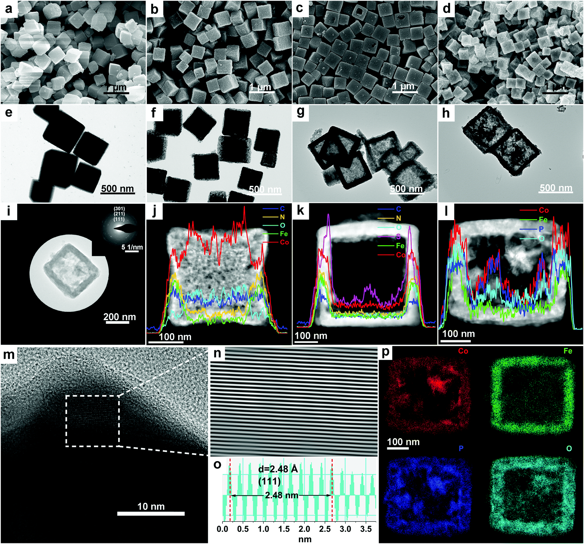 | ||
| Fig. 1 FESEM and TEM images of: (a and e) ZIF-67 nanocubes, (b and f) ZIF-67@CoFe–PB nanocubes, (c and g) Co–S@CoFe–PB nanoboxes, and (d and h) Co@CoFe–P nanoboxes. (i) High-resolution transmission electron microscopy (HR-TEM) image and the corresponding SAED pattern. (j–l) High-angle annular dark field-scanning transmission electron microscopy (HAADF-STEM) images and STEM-EDX line-scan profiles of ZIF-67@CoFe–PB nanocube, Co–S@CoFe–PB nanobox, and Co@CoFe–P nanobox particles. (m–o) HR-TEM image, corresponding inverse fast Fourier transformation (IFFT) image and line scan profile of a Co@CoFe–P nanobox particle. (p) STEM-EDX element mappings of Co@CoFe–P nanobox particles (red = Co, green = Fe, blue = P, cyan = O). | ||
Hierarchically nanostructured Co–S@CoFe–PB NBs were fabricated by using the as-obtained yolk–shell ZIF-67@CoFe–PB NCs as templates via a hydrothermal reaction with TAA at 120 °C (see experimental details in the ESI†). Furthermore, a wide range of characterization methods was employed to investigate the structural and morphological properties of the as-synthesized Co–S@CoFe–PB NBs (Fig. 1c, g, k and Fig. S5, S10–S13, ESI†). Based on our recent work and on previous studies on ZIF-67,21,34,61–63 the formation of Co–S@CoFe–PB NBs can be basically explained with an anion-exchange reaction between S2− from TAA and C4H5N2− from ZIF-67 during the sulfidation reaction (discussion and details in Fig. S5 and S11, ESI†). It should be pointed out that the chemical exchange between S2− and CN− in CoFe–PB can be neglected under the conditions applied in this study, mainly due to the insufficient kinetics at lower temperature and with the limited reaction time.62,64 As shown in Fig. 1k, STEM-EDX line-scan analysis of Co–S@CoFe–PB indicates a distinct elemental distribution of S within the shell. As expected, the inner layer of the shell displays intense S signals compared to the outer layer of the shell, suggesting the formation of hierarchically nanostructured cubes of Co–S@CoFe–PB NBs. Specifically, the newly formed Co–S species were mainly present in the inner layer of the shells, while the unreacted CoFe–PB compounds were preserved in the outer layer of the shell (Fig. 1k and Fig. S12, ESI†).
Hierarchical Co@CoFe–P NBs were obtained using a simple chemical vapor deposition method using NaH2PO2 as the phosphor source under Ar atmosphere (see experimental details in the ESI†). After phosphorization of the yolk–shell ZIF-67@CoFe–PB NC precursors with optimized experimental parameters, the as-prepared Co@CoFe–P NBs exhibit a well-defined hierarchical nanobox morphology (Fig. 1d and h). It was observed that both the amounts of NaH2PO2 and the phosphorization temperature influenced the morphologies of the final products (Fig. S17–S27, discussion and details in Fig. S21, and details in Discussion I, ESI†). Well-defined hierarchical nanobox architectures were achieved through the optimized experimental parameters with a mass ratio of 1![[thin space (1/6-em)]](https://www.rsc.org/images/entities/char_2009.gif) :20 between ZIF-67@CoFe–PB NCs and NaH2PO2 reacted at 350 °C for 2 h (Fig. 1d, h and Fig. S18m–p, ESI†). The SAED pattern of optimized Co@CoFe–P NBs (Fig. 1i) shows three characteristic diffraction rings, corresponding to the main exposed crystal planes (111), (211), and (301) of CoP (PDF No. 29-0497, S. G. Pnma), which agrees with the PXRD patterns (Fig. S24, ESI†). HR-TEM and the corresponding inverse fast Fourier transform (IFFT) images (Fig. 1m–o and Fig. S19, ESI†) of Co@CoFe–P NBs manifest a clear inter-planar spacing of 2.48 Å, which is assigned to the exposed (111) crystal plane of CoP (PDF No. 29-0497, S. G. Pnma). STEM-EDX line-scan analysis and element mappings (Fig. 1l and p) of Co@CoFe–P NBs illustrate that Co, P, and O are distributed in the inner and outer shells of the box-shaped particle, while Fe is mainly detected in the shell. The presence of O signals (Fig. 1l and p) is in principle due to the inevitable oxidation of P upon exposure to air.22,65–70 These results in their entirety support that the as-synthesized yolk–shell ZIF-67@CoFe–PB NC precursors are converted after phosphorization into hierarchical architectures of Co@CoFe–P NBs.
:20 between ZIF-67@CoFe–PB NCs and NaH2PO2 reacted at 350 °C for 2 h (Fig. 1d, h and Fig. S18m–p, ESI†). The SAED pattern of optimized Co@CoFe–P NBs (Fig. 1i) shows three characteristic diffraction rings, corresponding to the main exposed crystal planes (111), (211), and (301) of CoP (PDF No. 29-0497, S. G. Pnma), which agrees with the PXRD patterns (Fig. S24, ESI†). HR-TEM and the corresponding inverse fast Fourier transform (IFFT) images (Fig. 1m–o and Fig. S19, ESI†) of Co@CoFe–P NBs manifest a clear inter-planar spacing of 2.48 Å, which is assigned to the exposed (111) crystal plane of CoP (PDF No. 29-0497, S. G. Pnma). STEM-EDX line-scan analysis and element mappings (Fig. 1l and p) of Co@CoFe–P NBs illustrate that Co, P, and O are distributed in the inner and outer shells of the box-shaped particle, while Fe is mainly detected in the shell. The presence of O signals (Fig. 1l and p) is in principle due to the inevitable oxidation of P upon exposure to air.22,65–70 These results in their entirety support that the as-synthesized yolk–shell ZIF-67@CoFe–PB NC precursors are converted after phosphorization into hierarchical architectures of Co@CoFe–P NBs.
To further explore the impact of different cations or anions on the structural and morphological properties of the coordination polymer precursors, Co–S NBs, Co–PB NCs, Co–P NBs, Fe-PB NCs, Fe-P NBs, CoFe–PB NCs, CoFe–P NBs, Co@CoFe–O NBs, Co@CoFe–Se, and Co@CoFe–Te were prepared as well (see experimental details in the ESI†). According to our results, a distinct single-shell nanobox morphology was obtained for Co–S NBs (Fig. S14–S16, ESI†). Co–P, Fe–P, and CoFe–P NBs retain the initial cubic morphology but feature thicker shells (Fig. S28–S39, ESI†). As shown in Fig. S40–S42 (ESI†), the as-prepared Co@CoFe–O NBs show a well-defined double-shell nanobox architecture. In contrast, the cubic morphology cannot be preserved in the presence of Se and Te, shown in Fig. S43–S46 (ESI†).
Ex situ XAS characterization
The local coordination environments and electronic properties of the Co and Fe centers for the investigated catalysts were explored using ex situ X-ray absorption spectroscopy (XAS) (Fig. 2 and Fig. S47–S51, ESI†). To understand the effects of sulfidation on the electronic structure of ZIF-67@CoFe–PB NCs, ex situ XAS data were recorded for the samples before and after sulfidation (discussion and details in Fig. S47, ESI†). From the XAS investigations, we further corroborate that the anion-exchange reaction in Co–S@CoFe–PB NBs mainly occurred between S2− from TAA and C4H5N2− from ZIF-67.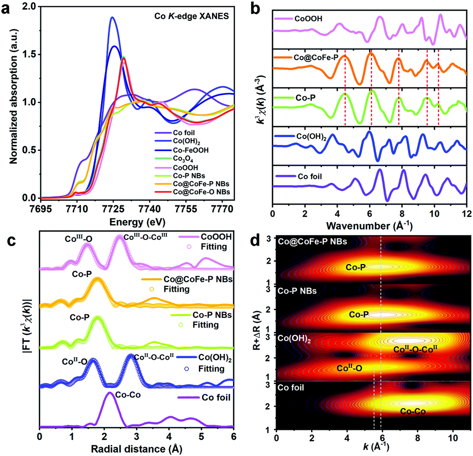 | ||
| Fig. 2 (a) Co K-edge XANES spectra of as-synthesized samples vs. references. (b) Co K-edge EXAFS spectra of the as-synthesized samples vs. references. (c) Fitting of the Co K-edge FT-EXAFS spectra of the as-synthesized samples vs. references. (d) Co K-edge WT contour profiles of the as-synthesized samples vs. references. | ||
Fig. 2a presents ex situ Co K-edge X-ray absorption near-edge structure (XANES) spectra of Co–P NBs, Co@CoFe–P NBs, Co@CoFe–O NBs, and the references Co foil, Co(OH)2, Co–FeOOH, Co3O4, and CoOOH. The rising absorption edge position of Co–P NBs is lower than that of Co(OH)2 but higher than that of Co foil, suggesting that the average valence state of Co centers in Co–P NBs is slightly lower than +2.12,23,59,66 To further explore the local electronic structure of the as-prepared catalysts, the XANES spectrum of Co–P NBs was calculated using ab initio finite difference methods using the model structure defined in the PDF card No. 29-0497 (S. G. Pnma) as shown in Fig. S48 (ESI†). Based on the XANES simulation results (Table S5, discussion and details in Fig. S48 and S49, ESI†), we conclude that the local coordination environments of Co ions in Co–P NBs originate from the asymmetric configuration of Co–P6−xOx moieties. The XAS data of Co@CoFe–P NBs (Fig. 2a and b) are similar to those of Co–P NBs except for a slight increase in the peak intensity at ∼7725 eV (XANES, Fig. 2a), suggesting an increased coordination number (CN) of Co–O bonds (denoted as CNCo–O) in Co@CoFe–P NBs. Based on previous reports,25,71–73 partial substitution of Co by Fe can weaken the orbital affinity for the 3d electrons and regulate the occupation of metal valence states, thus, lowering the energy barrier for the formation of M–O (M = Co, Fe) bonds. CNCo–O and CNCo–P in Co–P NBs were calculated to be 0.30 and 5.79, respectively, from fitting of the FT-EXAFS spectra (Fig. 2c and Table S5, ESI†). As expected, the as-prepared Co@CoFe–P NBs exhibit an increased CNCo–O of 0.61 and a decreased CNCo–P value of 5.29. These results are also evident in the wavelet transform (WT) of the EXAFS spectra (Fig. 2d), where the as-prepared Co@CoFe–P NBs show weaker signals in the intensity maximum at around 5.91 Å−1 (first Co–P coordination shell) compared with Co–P NBs. The Fe K-edge XAS data also display analogous features, evidencing the presence of asymmetric Co/Fe-P6−xOx moieties in the as-prepared Co@CoFe–P NBs (discussion and details in Fig. S50, ESI†). For comparison, the local atomic configurations of Co@CoFe–O NBs were also explored and they implied that the as-prepared oxide sample maintained a spinel-type crystal structure (discussion and details in Fig. S51, ESI†).
To unravel the surface chemical compositions of the as-synthesized samples, X-ray photoelectron spectroscopy (XPS) analyses were further carried out, and these results are also in agreement with the above XAS results (discussion and details in Fig. S52 and S53, ESI†).
Electrocatalytic performance
Their favorable intrinsic gas/ion-diffusion capability, their adequate interface for electrolyte penetration, and their tuneable electronic structure render the as-synthesized hierarchically hollow Co@CoFe–PB nanobox architectures32,35,57,59,61 promising candidates for efficient water splitting. To optimize the electrocatalytic performance of Co@CoFe–P NBs, the effects of synthetic parameter variations (e.g. NaH2PO2 amounts and reaction temperatures) on the catalytic performance were investigated first. The extrinsic influence of Ohmic contact resistance was eliminated with a 90% iR drop correction for all the investigated working electrodes (Fig. S54, ESI†).55,74,75 Measurement results (Fig. S55–S58, ESI†) show that the catalysts prepared at 350 °C with 400 mg of NaH2PO2 display the best electrocatalytic activities.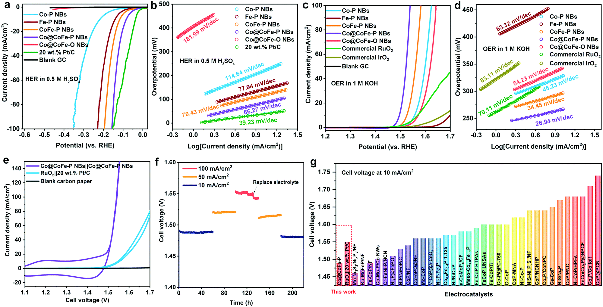 | ||
| Fig. 3 (a and c) Linear sweep voltammetry (LSV) curves with a scan rate of 5 mV s−1 at room temperature and (b and d) Tafel plots of the as-prepared Co–P NBs, Fe–P NBs, CoFe–P NBs, Co@CoFe–P NBs, and Co@CoFe–O NBs vs. commercial reference catalysts in 0.5 M H2SO4 (pH 0.2) for HER and 1.0 M KOH (pH 13.8) for OER, respectively. (e) Cyclic voltammetry (CV) curves of a two-electrode system assembled with Co@CoFe–P NBs||Co@CoFe–P NBs and RuO2||20 wt% Pt/C electrocatalysts in 1.0 M KOH. (f) Stability measurements of Co@CoFe–P NBs||Co@CoFe–P NBs loaded on carbon paper. (g) Summary of recent representative studies of overall water splitting electrocatalysts with their corresponding cell voltage at a current density of 10 mA cm−2 (Table S13, ESI†). | ||
Dynamics of active species derived from operando XAS
To probe the identity of the real catalytically active species and to understand the intrinsic structure–activity relationship during the water splitting half reactions, ex situ XPS and CV tests were first conducted on the investigated samples (Fig. S76 and S77 and details in Discussion II, ESI†). Our results indicate that the as-prepared phosphide materials undergo structural reconstruction during both HER and OER processes, which calls for the determination of the real active species involved in both reactions. To monitor the dynamic evolution of active species, we performed operando XAS measurements on the as-prepared Co/Fe phosphide samples during HER and OER under alkaline conditions (see Experimental details in the ESI,† and Fig. S78).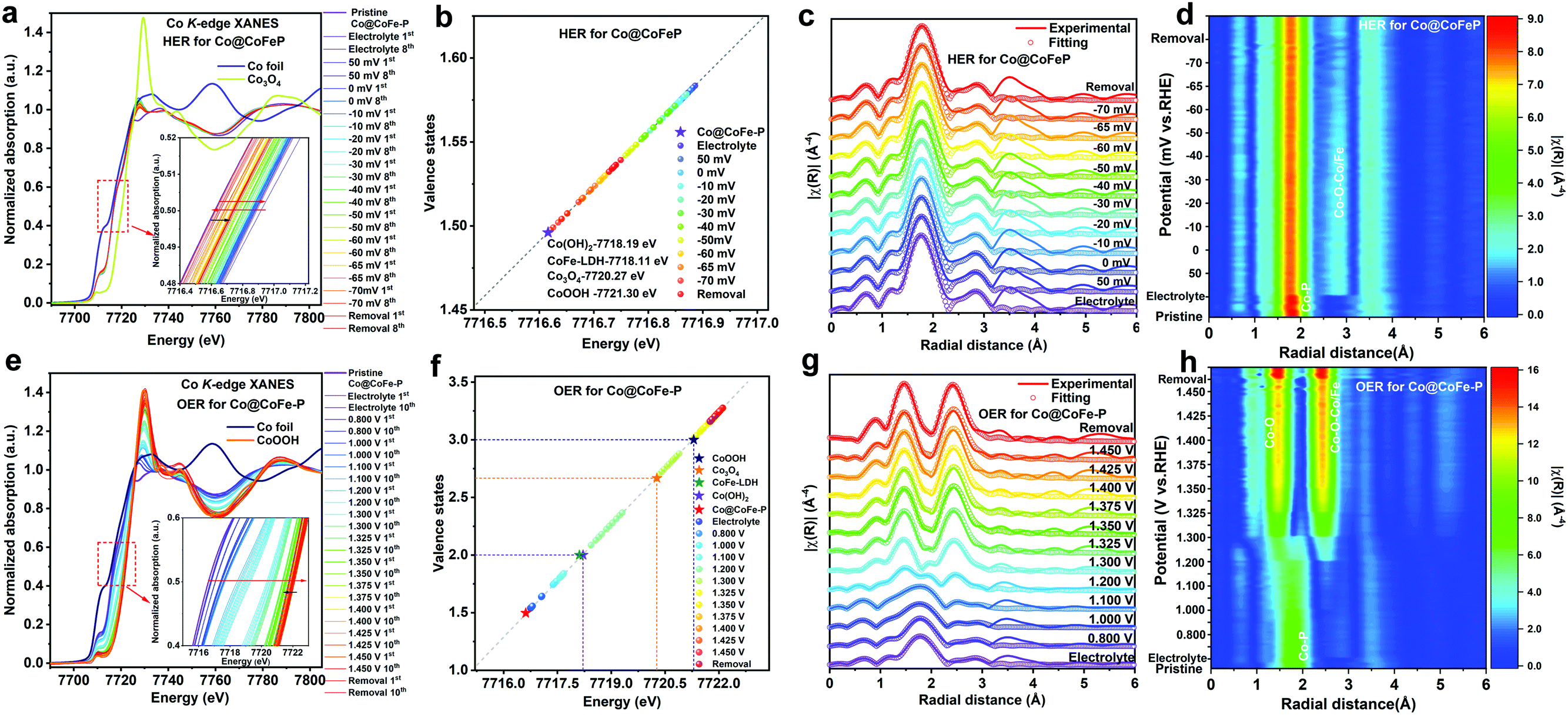 | ||
| Fig. 4 (a and e) Operando Co K-edge XANES spectra of Co@CoFe–P recorded at different potentials in 1.0 M KOH for HER and OER. (b and f) Calculated Co valence states of Co@CoFe–P recorded at different potentials in 1.0 M KOH for HER and OER. (c and g) Fitting of operando Co K-edge FT-EXAFS spectra (merged) of Co@CoFe–P recorded at different potentials in 1.0 M KOH for HER and OER. (d and h) 2D contour plots of operando Co K-edge FT-EXAFS spectra of Co@CoFe–P recorded at different potentials in 1.0 M KOH for HER and OER. (Note: when the potential is higher than the onset potential for OER (HER), the formation of gas bubbles drastically influences the quality of EXAFS data recorded in the transmission mode. Therefore, we only present the XANES data without showing the EXAFS data when there was a more intense gas evolution.) | ||
RRDE and operando Raman investigations
To further explore the dynamic evolution of the structural reconstruction and the real catalytically active species of the as-prepared phosphide-based catalysts during the OER process, rotating ring-disk electrode (RRDE) experiments were performed in Ar saturated 1.0 M KOH (discussion and details in Fig. S96 and S97, ESI†). As illustrated in Fig. S96 and S97 (ESI†), Co–P NBs show similar electrochemical behaviour as Co@CoFe–P NBs. Until CoIVO2 and (CoIV, FeIV)O2 are generated as active species, both Co–P NBs and Co@CoFe–P NBs do not show any obvious OER currents (Fig. S96 and S97, ESI†). Almost 100% faradaic efficiency is detected in both samples when the anodic potential reaches 1.525 V and 1.475 V vs. RHE, respectively. The RRDE results further verify that the structural reconstruction from phosphides to (oxy)hydroxides is a prerequisite for OER. Moreover, the in situ generated high valence states of CoIVO2 and (CoIV, FeIV)O2 species are responsible for the OER currents. Furthermore, operando Raman studies were carried out to investigate the surface catalytically active species during the HER and OER processes (Fig. S98 and S99, ESI†). As expected, similar vibrations assigned to metal-oxygen bonds are observed during both HER and OER processes. Regarding the HER with Co–P NBs (Fig. S98a, ESI†), two obvious peaks located at around 465 cm−1 and 670 cm−1 can be ascribed to the Eg and A1g modes of Co–O bonds, respectively.42,49,88 During the OER process with Co–P NBs (Fig. S98b, ESI†), two new peaks appear at 501 cm−1 and 570 cm−1, which arise from the Eg vibration of Co–O–Co moieties and the A1g mode of CoOOH, respectively.42,43,49,88 The operando Raman spectra of Co@CoFe–P NBs (Fig. S99, ESI†) also display similar vibration peaks during both HER and OER processes compared with that of Co–P NB, except that an additional peak observed at 725 cm−1 is assigned to Fe–O bonds.74,89–92 The RRDE and operando Raman observations in their entirety confirm that the in situ reconstructed metal–oxygen configurations play key roles during the water splitting process.DFT simulations
To gain further insight into the atomistic catalytic mechanisms, density functional theory (DFT) simulations were carried out for HER using a structure model of the as-prepared phosphide catalysts (see Experimental details in the ESI†). Based on our ex situ XPS, RRDE, operando XAS, and operando Raman studies, the in situ reconstructed P–Co–O–Fe–P moieties account for the excellent HER activity in Co@CoFe–P NBs. Herein, to simplify the calculation model, we partially removed one phosphorus atom and replaced it with one oxygen atom to simulate the impact of the in situ reconstructed configuration in the HER activity of the as-prepared Co@CoFe–P (denoted as O–Co@CoFe–P). Analyses of the projected density of states (pDOS) and of the metal 3d band centers of the as-proposed models reveal that partial incorporation of oxygen atom in Co@CoFe–P can regulate the energy barriers towards more favorable adsorption of HER intermediates (Fig. S100 and S101 Discussion IX, ESI†).To explain the catalytic activities in more detail, the adsorption free energies of the H* intermediates  for the proposed models were calculated. In general, an ideal HER catalyst should have a
  value near zero to facilitate both the H* adsorption and desorption based on the Sabatier principle.40,68,93–95 As depicted in Fig. 5a, b and Fig. S100 (ESI†), the calculated
  value at the Co site in Co–P exhibits the most negative value of −0.60 eV among the investigated models, indicating the strongest bonding between Co and H*. Nevertheless, after incorporation of Fe and O into the lattice of Co–P, the calculated
  value is remarkably decreased to −0.42 eV in Co@CoFe–P and −0.40 eV in O–Co@CoFe–P, respectively. Such smaller adsorption energies suggest that Fe substitution can improve the HER activity of Co–P. Besides H* adsorption, the adsorption and dissociation of water molecules are further kinetic barriers for HER under alkaline conditions.38,40 Therefore, the bonding energies of H2O molecules adsorbed on Co–P, Co@CoFe–P, and O–Co@CoFe–P were calculated. As shown in Fig. 5c, the adsorption of water molecules is more thermodynamically favorable on Co@CoFe–P and O–Co@CoFe–P compared with Co–P, which reflects their lower energy barrier for proton dissociation. The calculations (Fig. 5d) indicate that for Co–P a minimum energy barrier of 2.31 eV must be overcome to dissociate one H2O molecule, which is higher than those for Co@CoFe–P (1.98 eV) and O–Co@CoFe–P (1.88 eV). It is noteworthy that the active metal site for water adsorption and dissociation is relocated from the Co site in Co–P to the Fe site in Co@CoFe–P, owing to the higher 3d-band center position of Fe compared with Co (Fig. S100d, ESI†). This is in line with operando XAS analyses (Fig. 4b and Fig. S82b, ESI†), where the changes in the Fe oxidation state are greater than for Co sites during the HER process. After water dissociation is accomplished, the dissociated proton preferably moves to a neighboring Co site of the P–Co–O–Fe–P moieties to release H2 (Fig. 5a). On combining the above experimental and computational results, we conclude that partial substitution of Co by Fe in Co–P NBs can improve the HER activity by accelerating the water dissociation process and facilitating proton release. During the HER process, the in situ reconstructed O–Co@CoFe–P acts as real catalytically active species via its P–Co–O–Fe–P moieties. The formation of P–Co–O–Fe–P moieties not only optimizes
  but also facilitates the water dissociation process.
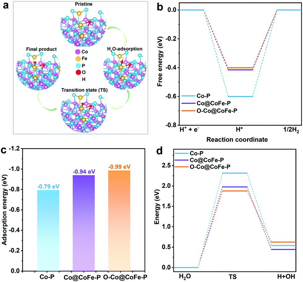 | ||
| Fig. 5 (a) Optimized adsorption slab models of O–Co@CoFe–P towards HER under alkaline conditions (TS = transition state). (b) Calculated free energy diagrams of H* intermediates adsorbed on three models. (c) Calculated adsorption energy of H2O molecules. (d) Calculated related reaction energy of water dissociation. | ||
For the OER, we demonstrate that the in situ reconstruction into CoIV–O–FeIV moieties plays a pivotal role in the OER activity of Co@CoFe–P NBs. Recent DFT investigations of Co-based materials reveal that the appearance of the oxygen-bridged CoIV–O–FeIV configurations leads to more preferable adsorption energies for OER intermediates (OO* or OOH*) compared with single Co sites or CoIV–O–CoIV configurations, thus accounting for the enhanced OER activity of the as-prepared Co@CoFe–P NBs.80,82–84,96,97
Perspectives
Concerning a broader catalyst design impact, our results indicate that anionic substitution strategies are promising to further optimize pnictide- and chalcogenide-based transition metal electrocatalysts for water splitting. The intrinsic thermodynamic properties of materials with different anions (e.g. O, P, S, Se, and Te) enable a local electronic regulation of the reconstructed active configurations12,13 for higher HER performance. Our operando results point to the stepwise transformation/oxidation and the subsequent formation of high valence states of metal ions in M–O–M moieties derived from anionic leaching during the OER process. This is regarded as a common denominator of TMCs and TMPs during the OER process. Concerning the advantages of TMCs and TMPs as OER catalysts compared with current operational catalysts based on metal (oxy)hydroxides, we believe that the in situ formation of highly disordered structures in TMCs and TMPs is a vital contribution to their higher OER activity (Fig. S87–S91, ESI†). However, the influence of residual pnictide/chalcogenide anions remaining on the surface or in the electrolyte still needs to be clarified in detail as well, especially via advanced surface sensitive techniques,85,96 such as in situ/operando soft XAS, XPS, and FT-IR techniques.Conclusions
In summary, we present a convenient self-templated strategy starting from versatile ZIF-67 nanocube (NC) and yolk–shell ZIF-67@CoFe–PB NC precursors for the preparation of a series of single-shell Co–S, Fe–P and Co–P nanoboxes (NBs), and hierarchically nanostructured Co–S@CoFe–PB, Co@CoFe–O, Co@CoFe–P, Co@CoFe–Se, and Co@CoFe–Te through facile chemical vapor deposition methods.The as-prepared Co@CoFe–P NBs are highly active and robust electrocatalysts for both hydrogen and oxygen evolution over a wide pH range (0–14). Co@CoFe–P NBs with tailored hierarchical architectures excel through promising catalytic performance with low HER overpotentials (at 10 mA cm−2) of 83 mV in 0.5 M H2SO4, 104 mV in 1.0 M KOH, and 150 mV in 1.0 M PBS, as well as 266 mV in 1.0 M KOH for OER. Inspired by the excellent HER and OER activities of the Co@CoFe–P NBs, we further assembled them as nanostructured bifunctional electrodes for overall water splitting. The as-synthesized Co@CoFe–P NBs provide a current density of 10 mA cm−2 at a very low cell voltage of 1.49 V. Most importantly, the device retains current densities of 10 mA cm−2, 50 mA cm−2, and 100 mA cm−2 for over 220 h without a significant decline, thus displaying a high potential for applied industrial electrocatalysis.
To identify the structural HER/OER reconstruction dynamics and the real catalytically active species of the as-prepared Co@CoFe–P NBs and reference Co–P, operando XAS and Raman spectra as well as RRDE studies were performed. Our results demonstrate that the active HER species in Co–P and Co@CoFe–P NBs arise from in situ reconstructed P–Co–O and P–Co–O–Fe–P configurations with low-valence metal sites (M0/M+). Moreover, DFT simulations confirm that these in situ reconstructed species lower the energy barriers for water dissociation and adsorption of H* intermediates, thereby enhancing the HER activity.
As for OER, we show that the as-prepared Co–P and Co@CoFe–P NBs undergo stepwise structural reconstructions into highly catalytically active CoIV–O–CoIV moieties and CoIV–O–FeIV configurations, respectively. Notably, the formation of such reactive CoIII/IV–O–FeIII/IV configurations is basically suppressed in reference Co–FeOOH under the same conditions, which reveals the specific advantages of phosphide-based catalysts for OER. On a larger scale, ex situ studies evidence that a range of as-prepared reference chalcogenides confirm the above trends through closely related general changes in the local electronic structure and coordination environments of their metal centers. Their individual dynamic structural reconstructions and real catalytically active species now remain to be specified with detailed in situ monitoring studies.
We present a convenient operando tracking approach for the structural reconstruction dynamics and the involved active catalytic species of TMPs during HER and OER. Our results on TMCs furthermore pave the way for future studies on HER in alkaline media via anionic substitution strategies to generate optimized reactive A–M–O–M–A (A: P, S, Se, and Te; M: Fe, Co, and Ni) configurations. The emerging design principles for new noble metal-free multifunctional electrocatalysts will expedite the progress of low-cost, applied energy conversion and storage systems.
Author contributions
G. R. Patzke supervised this project. Y. G. Zhao and G. R. Patzke contributed to the original idea, experimental strategy, and manuscript writing. Y. G. Zhao performed all syntheses, characterization studies, electrochemical performance tests, operando XAS tests, and data analyses, and prepared the manuscript. N. C. Dongfang, J. G. Lan, and M. Iannuzzi performed the DFT calculations and data analysis. C. A. Triana helped with the XANES simulations and XAS data analyses. C. Huang and D. Stoian helped with operando XAS experiments and data analysis. R. Erni conducted HR-TEM and HAADF-STEM characterization studies. W. C. Wan and J. G. Li helped with data analyses. L. Pan performed the sodium-ion battery tests. P. Zhang assisted with XPS measurements. All authors reviewed and commented on the manuscript before submission.Conflicts of interest
There are no conflicts to declare.Acknowledgements
Y. G. Zhao, N. C. Dongfang, C. A. Triana, C. Huang, W. C. Wan, J. G. Li, J. G. Lan, M. Iannuzzi, and G. R. Patzke thank the University of Zurich Research Priority Program Solar Light to Chemical Energy Conversion (URPP LightChEC) for financial support. G. R. Patzke is grateful to the Swiss National Science Foundation (Sinergia Grant No. CRSII2_160801) for financial support. R. Erni acknowledges funding from the European Research Council (ERC) under the EU Horizon 2020 Research and Innovation Program (Grant agreement no. 681312). The authors acknowledge the assistance and support of the Center for Microscopy and Image Analysis (UZH) in performing scanning electron microscopy experiments. The authors thank Dr W. van Beek and Dr D. Stoian (Swiss-Norwegian Beamline at the European Synchrotron Radiation Facility) for the allocation of synchrotron beamtime and for their support at the BM31 beamline for setting up the operando XAS tests. The authors thank Viviane Grange (Department of Chemistry, UZH) for conducting elemental analyses and ICP-MS measurements, and Hanspeter Stalder (Department of Chemistry, UZH) for his help with constructing electrochemical cells for operando experiments.References
- M. J. Craig and M. García-Melchor, Nat. Catal., 2020, 3, 967–968 CrossRef CAS.
- B. Zhang, L. Wang, Z. Cao, S. M. Kozlov, G. de Arquer, F. Pelayo, C. T. Dinh, J. Li, Z. Wang, X. Zheng, L. Zhang, Y. Wen, O. Voznyy, R. Comin, P. de Luna, T. Regier, W. Bi, E. E. Alp, C.-W. Pao, L. Zheng, Y. Hu, Y. Ji, Y. Li, Y. Zhang, L. Cavallo, H. Peng and E. H. Sargent, Nat. Catal., 2020, 3, 985–992 CrossRef CAS.
- J. Wang, S.-J. Kim, J. Liu, Y. Gao, S. Choi, J. Han, H. Shin, S. Jo, J. Kim, F. Ciucci, H. Kim, Q. Li, W. Yang, X. Long, S. Yang, S.-P. Cho, K. H. Chae, M. G. Kim, H. Kim and J. Lim, Nat. Catal., 2021, 4, 212–222 CrossRef CAS.
- J. Song, C. Wei, Z.-F. Huang, C. Liu, L. Zeng, X. Wang and Z. J. Xu, Chem. Soc. Rev., 2020, 49, 2196–2214 RSC.
- E. Fabbri, M. Nachtegaal, T. Binninger, X. Cheng, B.-J. Kim, J. Durst, F. Bozza, T. Graule, R. Schäublin, L. Wiles, M. Pertoso, N. Danilovic, K. E. Ayers and T. J. Schmidt, Nat. Mater., 2017, 16, 925–931 CrossRef CAS PubMed.
- W. Hao, R. Wu, H. Huang, X. Ou, L. Wang, D. Sun, X. Ma and Y. Guo, Energy Environ. Sci., 2020, 13, 102–110 RSC.
- K. Jiang, M. Luo, M. Peng, Y. Yu, Y.-R. Lu, T.-S. Chan, P. Liu, F. M. F. de Groot and Y. Tan, Nat. Commun., 2020, 11, 2701 CrossRef CAS PubMed.
- X. Zheng, B. Zhang, P. de Luna, Y. Liang, R. Comin, O. Voznyy, L. Han, G. de Arquer, F. Pelayo, M. Liu, C. T. Dinh, T. Regier, J. J. Dynes, S. He, H. L. Xin, H. Peng, D. Prendergast, X. Du and E. H. Sargent, Nat. Chem., 2018, 10, 149–154 CrossRef CAS PubMed.
- Y. Pan, K. Sun, Y. Lin, X. Cao, Y. Cheng, S. Liu, L. Zeng, W.-C. Cheong, D. Zhao, K. Wu, Z. Liu, Y. Liu, D. Wang, Q. Peng, C. Chen and Y. Li, Nano Energy, 2019, 56, 411–419 CrossRef CAS.
- K. Jiang, B. Liu, M. Luo, S. Ning, M. Peng, Y. Zhao, Y.-R. Lu, T.-S. Chan, F. M. F. de Groot and Y. Tan, Nat. Commun., 2019, 10, 1743 CrossRef PubMed.
- S.-F. Hung, Y. Zhu, G.-Q. Tzeng, H.-C. Chen, C.-S. Hsu, Y.-F. Liao, H. Ishii, N. Hiraoka and H. M. Chen, ACS Energy Lett., 2019, 4, 2813–2820 CrossRef CAS.
- Y. Zhu, H.-C. Chen, C.-S. Hsu, T.-S. Lin, C.-J. Chang, S.-C. Chang, L.-D. Tsai and H. M. Chen, ACS Energy Lett., 2019, 4, 987–994 CrossRef CAS.
- Y. Shi, M. Li, Y. Yu and B. Zhang, Energy Environ. Sci., 2020, 13, 4564–4582 RSC.
- D. Cao, D. Liu, S. Chen, O. A. Moses, X. Chen, W. Xu, C. Wu, L. Zheng, S. Chu, H. Jiang, C. Wang, B. Ge, X. Wu, J. Zhang and L. Song, Energy Environ. Sci., 2021, 14, 906–915 RSC.
- J. Song, ACS Energy Lett., 2017, 2, 1937–1938 CrossRef.
- Y. Zhang, L. Gao, E. J. M. Hensen and J. P. Hofmann, ACS Energy Lett., 2018, 3, 1360–1365 CrossRef CAS PubMed.
- Y. Zhang and L. Song, ChemCatChem, 2020, 12, 3621–3638 CrossRef CAS.
- A. Sivanantham, P. Ganesan, A. Vinu and S. Shanmugam, ACS Catal., 2020, 10, 463–493 CrossRef CAS.
- A. Indra, P. W. Menezes, I. Zaharieva, H. Dau and M. Driess, J. Mater. Chem. A, 2020, 8, 2637–2643 RSC.
- K. Fan, H. Zou, Y. Lu, H. Chen, F. Li, J. Liu, L. Sun, L. Tong, M. F. Toney, M. Sui and J. Yu, ACS Nano, 2018, 12, 12369–12379 CrossRef CAS PubMed.
- M. Wang, C.-L. Dong, Y.-C. Huang and S. Shen, ACS Catal., 2020, 10, 1855–1864 CrossRef.
- S. Sun, X. Zhou, B. Cong, W. Hong and G. Chen, ACS Catal., 2020, 10, 9086–9097 CrossRef CAS.
- K. Xu, Y. Sun, X. Li, Z. Zhao, Y. Zhang, C. Li and H. J. Fan, ACS Mater. Lett., 2020, 2, 736–743 CrossRef CAS.
- Y. Shi, W. Du, W. Zhou, C. Wang, S. Lu, S. Lu and B. Zhang, Angew. Chem., Int. Ed., 2020, 59, 22470–22474 CrossRef CAS PubMed.
- J.-Y. Zhang, Y. Yan, B. Mei, R. Qi, T. He, Z. Wang, W. Fang, S. Zaman, Y. Su, S. Ding and B. Y. Xia, Energy Environ. Sci., 2021, 14, 365–373 RSC.
- J. Huang, Y. Li, Y. Zhang, G. Rao, C. Wu, Y. Hu, X. Wang, R. Lu, Y. Li and J. Xiong, Angew. Chem., Int. Ed., 2019, 58, 17458–17464 CrossRef CAS PubMed.
- Y. Dou, C.-T. He, L. Zhang, H. Yin, M. Al-Mamun, J. Ma and H. Zhao, Nat. Commun., 2020, 11, 1664 CrossRef CAS PubMed.
- X. Zheng, X. Han, Y. Cao, Y. Zhang, D. Nordlund, J. Wang, S. Chou, H. Liu, L. Li, C. Zhong, Y. Deng and W. Hu, Adv. Mater., 2020, 32, 2000607 CrossRef CAS PubMed.
- T. Zhao, X. Shen, Y. Wang, R. K. Hocking, Y. Li, C. Rong, K. Dastafkan, Z. Su and C. Zhao, Adv. Funct. Mater., 2021, 31, 2100614 CrossRef CAS.
- W. Zhao, C. Zhang, F. Geng, S. Zhuo and B. Zhang, ACS Nano, 2014, 8, 10909–10919 CrossRef CAS PubMed.
- Z. Wu, Q. Gan, X. Li, Y. Zhong and H. Wang, J. Phys. Chem. C, 2018, 122, 2848–2853 CrossRef CAS.
- H. Zhang, W. Zhou, J. Dong, X. F. Lu and X. W. Lou, Energy Environ. Sci., 2019, 12, 3348–3355 RSC.
- Y. Zhao, J. Zhang, Y. Xie, B. Sun, J. Jiang, W.-J. Jiang, S. Xi, H. Y. Yang, K. Yan, S. Wang, X. Guo, P. Li, Z. Han, X. Lu, H. Liu and G. Wang, Nano Lett., 2021, 21, 823–832 CrossRef CAS PubMed.
- Z.-F. Huang, J. Song, K. Li, M. Tahir, Y.-T. Wang, L. Pan, L. Wang, X. Zhang and J.-J. Zou, J. Am. Chem. Soc., 2016, 138, 1359–1365 CrossRef CAS PubMed.
- C. Zhang, Y. Huang, Y. Yu, J. Zhang, S. Zhuo and B. Zhang, Chem. Sci., 2017, 8, 2769–2775 RSC.
- C. Zhang, Y. Shi, Y. Yu, Y. Du and B. Zhang, ACS Catal., 2018, 8, 8077–8083 CrossRef CAS.
- S. Zhuo, Y. Shi, L. Liu, R. Li, L. Shi, D. H. Anjum, Y. Han and P. Wang, Nat. Commun., 2018, 9, 3132 CrossRef PubMed.
- Q. Fu, X. Wang, J. Han, J. Zhong, T. Zhang, T. Yao, C. Xu, T. Gao, S. Xi, C. Liang, L. Xu, P. Xu and B. Song, Angew. Chem., Int. Ed., 2021, 60, 259–267 CrossRef CAS PubMed.
- X. Liu, Y. Yao, H. Zhang, L. Pan, C. Shi, X. Zhang, Z.-F. Huang and J.-J. Zou, ACS Sustainable Chem. Eng., 2020, 8, 17828–17838 CrossRef CAS.
- D. Zhao, K. Sun, W.-C. Cheong, L. Zheng, C. Zhang, S. Liu, X. Cao, K. Wu, Y. Pan, Z. Zhuang, B. Hu, D. Wang, Q. Peng, C. Chen and Y. Li, Angew. Chem., Int. Ed., 2020, 59, 8982–8990 CrossRef CAS PubMed.
- Y. Zhu, J. Wang, H. Chu, Y.-C. Chu and H. M. Chen, ACS Energy Lett., 2020, 5, 1281–1291 CrossRef CAS.
- J. Liu, Q. Hu, Y. Wang, Z. Yang, X. Fan, L.-M. Liu and L. Guo, Proc. Natl. Acad. Sci. U. S. A., 2020, 117, 21906–21913 CrossRef CAS PubMed.
- J. N. Hausmann, S. Mebs, K. Laun, I. Zebger, H. Dau, P. W. Menezes and M. Driess, Energy Environ. Sci., 2020, 13, 3607–3619 RSC.
- L. J. Enman, M. B. Stevens, M. H. Dahan, M. R. Nellist, M. C. Toroker and S. W. Boettcher, Angew. Chem., Int. Ed., 2018, 57, 12840–12844 CrossRef CAS PubMed.
- J. Timoshenko and B. Roldan Cuenya, Chem. Rev., 2021, 121, 882–961 CrossRef CAS PubMed.
- B.-J. Kim, E. Fabbri, D. F. Abbott, X. Cheng, A. H. Clark, M. Nachtegaal, M. Borlaf, I. E. Castelli, T. Graule and T. J. Schmidt, J. Am. Chem. Soc., 2019, 141, 5231–5240 CrossRef CAS PubMed.
- S. Song, J. Zhou, X. Su, Y. Wang, J. Li, L. Zhang, G. Xiao, C. Guan, R. Liu, S. Chen, H.-J. Lin, S. Zhang and J.-Q. Wang, Energy Environ. Sci., 2018, 11, 2945–2953 RSC.
- L. Cao, Q. Luo, W. Liu, Y. Lin, X. Liu, Y. Cao, W. Zhang, Y. Wu, J. Yang, T. Yao and S. Wei, Nat. Catal., 2019, 2, 134–141 CrossRef CAS.
- Z. Kou, Y. Yu, X. Liu, X. Gao, L. Zheng, H. Zou, Y. Pang, Z. Wang, Z. Pan, J. He, S. J. Pennycook and J. Wang, ACS Catal., 2020, 10, 4411–4419 CrossRef CAS.
- W. Wan, C. A. Triana, J. Lan, J. Li, C. S. Allen, Y. Zhao, M. Iannuzzi and G. R. Patzke, ACS Nano, 2020, 14, 13279–13293 CrossRef CAS PubMed.
- Z. Xiao, Y.-C. Huang, C.-L. Dong, C. Xie, Z. Liu, S. Du, W. Chen, D. Yan, L. Tao, Z. Shu, G. Zhang, H. Duan, Y. Wang, Y. Zou, R. Chen and S. Wang, J. Am. Chem. Soc., 2020, 142, 12087–12095 CrossRef CAS PubMed.
- F. Dionigi, Z. Zeng, I. Sinev, T. Merzdorf, S. Deshpande, M. B. Lopez, S. Kunze, I. Zegkinoglou, H. Sarodnik, D. Fan, A. Bergmann, J. Drnec, J. F. de Araujo, M. Gliech, D. Teschner, J. Zhu, W.-X. Li, J. Greeley, B. R. Cuenya and P. Strasser, Nat. Commun., 2020, 11, 2522 CrossRef CAS PubMed.
- Y. Zhou, S. Sun, J. Song, S. Xi, B. Chen, Y. Du, A. C. Fisher, F. Cheng, X. Wang, H. Zhang and Z. J. Xu, Adv. Mater., 2018, 30, 1802912 CrossRef PubMed.
- Z.-F. Huang, J. Song, Y. Du, S. Xi, S. Dou, J. M. V. Nsanzimana, C. Wang, Z. J. Xu and X. Wang, Nat. Energy, 2019, 4, 329–338 CrossRef CAS.
- Y. Zhao, W. Wan, Y. Chen, R. Erni, C. A. Triana, J. Li, C. K. Mavrokefalos, Y. Zhou and G. R. Patzke, Adv. Energy Mater., 2020, 10, 2002228 CrossRef CAS.
- Y. Duan, J. Y. Lee, S. Xi, Y. Sun, J. Ge, S. J. H. Ong, Y. Chen, S. Dou, F. Meng, C. Diao, A. C. Fisher, X. Wang, G. G. Scherer, A. Grimaud and Z. J. Xu, Angew. Chem., Int. Ed., 2021, 60, 7418–7425 CrossRef CAS PubMed.
- H. Hu, B. Y. Guan and X. W. Lou, Chem, 2016, 1, 102–113 CAS.
- H. Liu, J. Guan, S. Yang, Y. Yu, R. Shao, Z. Zhang, M. Dou, F. Wang and Q. Xu, Adv. Mater., 2020, 32, 2003649 CrossRef CAS PubMed.
- X. Wang, L. Yu, B. Y. Guan, S. Song and X. W. Lou, Adv. Mater., 2018, 30, 1801211 CrossRef PubMed.
- Z. Li, X. Zhang, Y. Kang, C. C. Yu, Y. Wen, M. Hu, D. Meng, W. Song and Y. Yang, Adv. Sci., 2021, 8, 2002631 CrossRef CAS PubMed.
- H. Hu, L. Han, M. Yu, Z. Wang and X. W. Lou, Energy Environ. Sci., 2016, 9, 107–111 RSC.
- Y. Zhao, C. K. Mavrokefalos, P. Zhang, R. Erni, J. Li, C. A. Triana and G. R. Patzke, Chem. Mater., 2020, 32, 1371–1383 CrossRef CAS.
- W. Wang, H. Yan, U. Anand and U. Mirsaidov, J. Am. Chem. Soc., 2021, 143, 1854–1862 CrossRef CAS PubMed.
- G. Zhang, Y. Li, X. Xiao, Y. Shan, Y. Bai, H.-G. Xue, H. Pang, Z. Tian and Q. Xu, Nano Lett., 2021, 21, 3016–3025 CrossRef CAS PubMed.
- J. Wang, Y. Gao, H. Kong, J. Kim, S. Choi, F. Ciucci, Y. Hao, S. Yang, Z. Shao and J. Lim, Chem. Soc. Rev., 2020, 49, 9154–9196 RSC.
- Y. Pan, K. Sun, S. Liu, X. Cao, K. Wu, W.-C. Cheong, Z. Chen, Y. Wang, Y. Li, Y. Liu, D. Wang, Q. Peng, C. Chen and Y. Li, J. Am. Chem. Soc., 2018, 140, 2610–2618 CrossRef CAS PubMed.
- Z. Li, W. Niu, Z. Yang, A. Kara, Q. Wang, M. Wang, M. Gu, Z. Feng, Y. Du and Y. Yang, Energy Environ. Sci., 2020, 13, 3110–3118 RSC.
- Z. Chen, M. Chen, X. Yan, H. Jia, B. Fei, Y. Ha, H. Qing, H. Yang, M. Liu and R. Wu, ACS Nano, 2020, 14, 6968–6979 CrossRef CAS PubMed.
- Y. Dong, T. Tian, C. Xu, K. Ma, W. Sun and Y. Ding, J. Catal., 2020, 382, 13–21 CrossRef CAS.
- P. Hou, D. Li, N. Yang, J. Wan, C. Zhang, X. Zhang, H. Jiang, Q. Zhang, L. Gu and D. Wang, Angew. Chem., Int. Ed., 2021, 60, 6926–6931 CrossRef CAS PubMed.
- F. M. F. de Groot, S. Pizzini, A. Fontaine, K. Hämäläinen, C. C. Kao and J. B. Hastings, Phys. Rev. B: Condens. Matter Mater. Phys., 1995, 51, 1045–1052 CrossRef CAS PubMed.
- A. P. Grosvenor, R. G. Cavell and A. Mar, J. Solid State Chem., 2007, 180, 2702–2712 CrossRef CAS.
- A. P. Grosvenor, R. G. Cavell and A. Mar, J. Solid State Chem., 2008, 181, 2549–2558 CrossRef CAS.
- J. Yu, Q. Cao, Y. Li, X. Long, S. Yang, J. K. Clark, M. Nakabayashi, N. Shibata and J.-J. Delaunay, ACS Catal., 2019, 9, 1605–1611 CrossRef CAS.
- J. Yu, J. Wang, X. Long, L. Chen, Q. Cao, C. Qiu, J. Lim and S. Yang, Adv. Energy Mater., 2021, 11, 2002731 CrossRef CAS.
- M. Zheng, Y. Ding, L. Yu, X. Du and Y. Zhao, Adv. Funct. Mater., 2017, 27, 1605846 CrossRef.
- B. Pattengale, Y. Huang, X. Yan, S. Yang, S. Younan, W. Hu, Z. Li, S. Lee, X. Pan, J. Gu and J. Huang, Nat. Commun., 2020, 11, 4114 CrossRef CAS PubMed.
- T. Wu, S. Sun, J. Song, S. Xi, Y. Du, B. Chen, W. A. Sasangka, H. Liao, C. L. Gan, G. G. Scherer, L. Zeng, H. Wang, H. Li, A. Grimaud and Z. J. Xu, Nat. Catal., 2019, 2, 763–772 CrossRef CAS.
- L. Bai, C.-S. Hsu, D. T. L. Alexander, H. M. Chen and X. Hu, J. Am. Chem. Soc., 2019, 141, 14190–14199 CrossRef CAS PubMed.
- J. Zhou, Y. Wang, X. Su, S. Gu, R. Liu, Y. Huang, S. Yan, J. Li and S. Zhang, Energy Environ. Sci., 2019, 12, 739–746 RSC.
- G. K. Schweitzer and L. L. Pesterfield, The Aqueous Chemistry of the Elements, Oxford University Press, 2010 Search PubMed.
- A. Bergmann, T. E. Jones, E. Martinez Moreno, D. Teschner, P. Chernev, M. Gliech, T. Reier, H. Dau and P. Strasser, Nat. Catal., 2018, 1, 711–719 CrossRef CAS.
- A. Moysiadou, S. Lee, C.-S. Hsu, H. M. Chen and X. Hu, J. Am. Chem. Soc., 2020, 142, 11901–11914 CrossRef CAS PubMed.
- J. T. Mefford, Z. Zhao, M. Bajdich and W. C. Chueh, Energy Environ. Sci., 2020, 13, 622–634 RSC.
- J. T. Mefford, A. R. Akbashev, M. Kang, C. L. Bentley, W. E. Gent, H. D. Deng, D. H. Alsem, Y.-S. Yu, N. J. Salmon, D. A. Shapiro, P. R. Unwin and W. C. Chueh, Nature, 2021, 593, 67–73 CrossRef CAS PubMed.
- M. Risch, F. Ringleb, M. Kohlhoff, P. Bogdanoff, P. Chernev, I. Zaharieva and H. Dau, Energy Environ. Sci., 2015, 8, 661–674 RSC.
- J. G. McAlpin, Y. Surendranath, M. Dinca, T. A. Stich, S. A. Stoian, W. H. Casey, D. G. Nocera and R. D. Britt, J. Am. Chem. Soc., 2010, 132, 6882–6883 CrossRef CAS PubMed.
- W. Zheng, M. Liu and L. Y. S. Lee, ACS Catal., 2020, 10, 81–92 CrossRef CAS.
- S. Jiao, X. Fu, S. Wang and Y. Zhao, Energy Environ. Sci., 2021, 14, 1722–1770 RSC.
- S. Réguer, D. Neff, L. Bellot-Gurlet and P. Dillmann, J. Raman Spectrosc., 2007, 38, 389–397 CrossRef.
- L. Bai, S. Lee and X. Hu, Angew. Chem., Int. Ed., 2021, 60, 3095–3103 CrossRef CAS PubMed.
- B. Chakraborty, R. Beltrán-Suito, J. N. Hausmann, S. Garai, M. Driess and P. W. Menezes, Adv. Energy Mater., 2020, 10, 2001377 CrossRef CAS.
- Y. An, X. Long, M. Ma, J. Hu, H. Lin, D. Zhou, Z. Xing, B. Huang and S. Yang, Adv. Energy Mater., 2019, 9, 1901454 CrossRef CAS.
- H. Feng, L. Tang, G. Zeng, J. Yu, Y. Deng, Y. Zhou, J. Wang, C. Feng, T. Luo and B. Shao, Nano Energy, 2020, 67, 104174 CrossRef CAS.
- Z. Wang, Z. Lin, J. Deng, S. Shen, F. Meng, J. Zhang, Q. Zhang, W. Zhong and L. Gu, Adv. Energy Mater., 2021, 11, 2003023 CrossRef CAS.
- J. Li, C. A. Triana, W. Wan, D. P. Adiyeri Saseendran, Y. Zhao, S. E. Balaghi, S. Heidari and G. R. Patzke, Chem. Soc. Rev., 2021, 50, 2444–2485 RSC.
- N. Zhang, X. Feng, D. Rao, X. Deng, L. Cai, B. Qiu, R. Long, Y. Xiong, Y. Lu and Y. Chai, Nat. Commun., 2020, 11, 4066 CrossRef CAS PubMed.
Footnote |
| † Electronic supplementary information (ESI) available. See DOI: 10.1039/d1ee02249k |
| This journal is © The Royal Society of Chemistry 2022 |