
 Open Access Article
 This Open Access Article is licensed under a Creative Commons Attribution-Non Commercial 3.0 Unported Licence
Towards Watt-scale hydroelectric energy harvesting by Ti3C2Tx-based transpiration-driven electrokinetic power generators†
Jaehyeong
Bae‡
 ab,
Min Soo
Kim‡
a,
Taegon
Oh
c,
Bong Lim
Suh
d,
Tae Gwang
Yun
e,
Seungjun
Lee
cf,
Kahyun
Hur
d,
Yury
Gogotsi
g,
Chong Min
Koo
cfh and
Il-Doo
Kim
*a
ab,
Min Soo
Kim‡
a,
Taegon
Oh
c,
Bong Lim
Suh
d,
Tae Gwang
Yun
e,
Seungjun
Lee
cf,
Kahyun
Hur
d,
Yury
Gogotsi
g,
Chong Min
Koo
cfh and
Il-Doo
Kim
*a
aDepartment of Materials Science and Engineering, Korea Advanced Institute of Science and Technology (KAIST), 291 Daehak-ro, Yuseong-gu, Daejeon, 34141, Republic of Korea. E-mail: idkim@kaist.ac.kr
bJohn A. Paulson School of Engineering and Applied Sciences, Harvard University, Cambridge, MA 02138, USA. E-mail: gbae@seas.harvard.edu
cMaterials Architecturing Research Center, Korea Institute of Science and Technology, Seoul 02792, Republic of Korea
dExtreme Materials Research Center, Advanced Materials Research Division, Korea Institute of Science and Technology, Seoul 02792, Republic of Korea
eDepartment of Materials Science and Engineering, Myongji University, Yongin, Gyeonggi 17058, Republic of Korea
fKU-KIST Graduate School of Converging Science and Technology, Korea University, Seoul 02841, Republic of Korea
gDepartment of Materials Science and Engineering, and A. J. Drexel Nanomaterials Institute, Drexel University, 3141 Chestnut Street, Philadelphia, PA 19104, USA
hDivision of Nano & Information Technology, KIST School, University of Science and Technology, Seoul 02792, Republic of Korea
First published on 13th October 2021
Abstract
Nano-hydroelectric technology utilizes hydraulic flow through electronically conducting nanomaterials to generate electricity in a simple, renewable, ubiquitous, and environmentally friendly manner. To date, several designs of nano-hydroelectric devices have been devised to maximize the electrokinetic interactions between water molecules and nanomaterials. However, the reported power generation of the state-of-the-art nano-hydroelectric generators is not sufficient for practical use, as tens of thousands of units were required to operate low-power electronics on a mW scale. Here, we utilize titanium carbide (Ti3C2Tx) MXene nanosheets, which have advantageous properties including metal-like conductivity and hydrophilicity, to facilitate the electrokinetic conversion of the transpiration–driven electrokinetic power generator (TEPG) with a remarkably improved energy generation efficiency compared to that of carbon-based TEPG. The Ti3C2Tx MXene-based TEPG delivered a high pseudo-streaming current of 120 μA by the fast capillary flow promoted by MXene sheets coated on cotton fabric. The strong cationic affinity of Ti3C2Tx enables the generator to achieve an output of 0.68 V and 2.73 mA when NaCl solution is applied. Moreover, incorporation of a conducting polymer (i.e., Ti3C2Tx/polyaniline composite) enhanced the ionic diffusivity while maintaining the electrical network of Ti3C2Tx. The optimized Ti3C2Tx/polyaniline composite TEPG generated a maximum voltage of 0.54 V, a current of 8.2 mA, and a specific power density of 30.9 mW cm−3, which was sufficient to successfully charge a commercial Li-ion battery as well as low-power electronics and devices with a volume of 6.72 cm3.
Broader contextNano-hydroelectric devices utilize earth-abundant water as a resource to generate electricity, which is an emerging technology in the energy field. One of the hurdles for this technology was low energy output that even the state-of-the-art nano-hydroelectric devices could hardly be used as practical energy sources. For this reason, various active materials have been investigated based on their morphology, size, conductivity, surface chemistry, and arrangements to maximize their compatibility with water to improve energy transformation efficiency. One of the most promising candidates is MXenes, a two-dimensional transition metal carbide or nitride having a thickness of around a few atoms, metallic conductivity, and hydrophilicity. Herein, we used Ti3C2Tx MXenes as an active material for transpiration-driven electrokinetic power generators (TEPG) to improve energy transformation efficiency. The size, conductivity, arrangements of MXene nanosheets, and their combination with polyaniline were investigated to find the optimal Mxene-based TEPG composition. Besides, energy performances were analyzed using water and electrolyte solutions to study the role of electrolytes on improved energy generation efficiency. As a result, we could maximize the electrokinetic energy conversion of the MXene-based power generator up to the mW scale and charge a commercial battery for the first time by using TEPGs. |
Introduction
The harvesting of energy from ambient sources on-demand has been widely explored in recent years,1–5 and as a result, various strategies such as piezo-/triboelectrics,6–8 photovoltaics,9–11 thermoelectrics, and nano-hydroelectrics12–14 have successfully been demonstrated for the effective conversion of mechanical, solar, thermal, and hydrodynamic energy, respectively, into electricity. Among these, the nano-hydroelectric technology has the greatest freedom of utility as it uses water, an earth-abundant and ubiquitous resource, for energy production. In addition, since the nano-hydroelectric generator simply relies on the spontaneous electrokinetic activity of water on the interface of conductive nanomaterials to transform nanoscale hydraulic energy into electricity,3,13–17 it can be constructed with a wide variety of materials, as long as they have a high surface area, high conductivity, and hydrophilicity. For instance, graphene, various carbons, polymers, and biomolecules have all been demonstrated as potential electrokinetic converting materials for nano-hydroelectrics.13,18,19 This ubiquity in materials selection provides a greater freedom for designing nano-hydroelectrics to target specific design requirements. Moreover, recent developments have made it possible to harvest energy from the vapor state as well, greatly expanding the versatility of nano-hydroelectrics.15,17,20 However, despite these appealing opportunities presented by the nano-hydroelectric technology, most of the devices show unsatisfactory power generation performance, even with the high volumetric or areal power outputs which consider the dimensions of the active materials only for calculation. In terms of the devices for power generation, it remains a grand challenge for hydroelectrics to produce electric power on the Watt-scale necessary for practical applications.To this end, we recently demonstrated a transpiration-driven electrokinetic power generator (TEPG) that overcame the limits of nano-hydroelectric devices by exploiting the hydraulic flow of applied water through a hydrophilic cotton membrane coated with conductive carbon black particles.3,13 When water is introduced, an electrical double layer is formed on the surface of the electrokinetic converting materials (i.e., carbon black) on TEPGs. The potential drop across wet and dry regimes generates an electric current that is coupled with the capillary-driven hydraulic flow, a phenomenon which is referred to as pseudo-streaming current.13 However, although this device demonstrated the highest power efficiency among the reported hydroelectric generators (2.02 μW), it was still insufficient to supply devices with adequate power for practical operations, even when thousands of connected units were operated simultaneously.3 The limitation of this device could be found in the inefficient packing of spherical carbon black particles, which causes weaker hydraulic interactions and electrical connections (Fig. S1, ESI†). Also, the surface of the carbon black particles was covered by surfactant molecules to compensate for their intrinsic hydrophobicity, leading to a significant ohmic loss.3,13
As such, there is a persisting need to identify electrokinetic converting materials which would maximize the power generation efficiency of nano-hydroelectric generators. It is theorized that a high power density of up to about 100 W cm−2 is possible to achieve by optimizing the device design and choice of materials.21 In this regard, the energy density could be improved using materials with high affinity to such ions as H3O+, Na+, or Ca2+![[thin space (1/6-em)]](https://www.rsc.org/images/entities/char_2009.gif) 3,13 to amplify the build-up of electric potential. In this regard, nanomaterials with significant surface activity such as nanoporous carbon, graphene, conductive polymers, and MXenes are promising candidates for nano-hydroelectric generators operating at high voltages.22–24 In particular, MXenes show much promise as electrokinetic conversion materials because of their metal-like electrical conductivity, hydrophilicity, and two-dimensional (2D) structure.25,26 We hypothesize therefore that MXene-based generators should result in high pseudo-streaming current rates and achieve energy densities of unprecedented levels.27 In this study, we explored the possibility of a MXene-based nano-hydroelectric generator using Ti3C2Tx, a type of MXene that is widely regarded as having the highest conductivity. Looking ahead, we believe that our work contributes significantly to breakthrough developments in the TEPG technology.
3,13 to amplify the build-up of electric potential. In this regard, nanomaterials with significant surface activity such as nanoporous carbon, graphene, conductive polymers, and MXenes are promising candidates for nano-hydroelectric generators operating at high voltages.22–24 In particular, MXenes show much promise as electrokinetic conversion materials because of their metal-like electrical conductivity, hydrophilicity, and two-dimensional (2D) structure.25,26 We hypothesize therefore that MXene-based generators should result in high pseudo-streaming current rates and achieve energy densities of unprecedented levels.27 In this study, we explored the possibility of a MXene-based nano-hydroelectric generator using Ti3C2Tx, a type of MXene that is widely regarded as having the highest conductivity. Looking ahead, we believe that our work contributes significantly to breakthrough developments in the TEPG technology.
Results and discussion
Ti3C2Tx-Based transpiration driven electrokinetic power generator
Herein, we report a design that utilizes Ti3C2Tx as an electrokinetic converting TEPG material (Fig. 1a). Ti3C2Tx is a type of MXene with a nanosheet morphology (≈0.95 nm layer thickness) that possesses the highest electrical conductivity (up to 20000 S cm−1) among other materials in the MXene family, based on which it has been widely investigated as an active material for supercapacitors and many other energy applications.28–31 Moreover, the strong surface negativity of Ti3C2Tx sheets induces a high affinity toward both monovalent and divalent cations and promotes the build-up of electrical double layers, a behaviour which could be controlled by tuning their interlayer spacing.32,33 Also, unlike the spherical carbon nanoparticles that show poor spatial packing, the 2D Ti3C2Tx nanosheets tightly wrap around each cotton fibre completely to reinforce the electrical network with minimized Ohmic loss (Fig. 1b and Fig. S2, ESI†), in agreement with previous studies.34 Altogether, these properties make Ti3C2Tx highly attractive for utilization in TEPG.
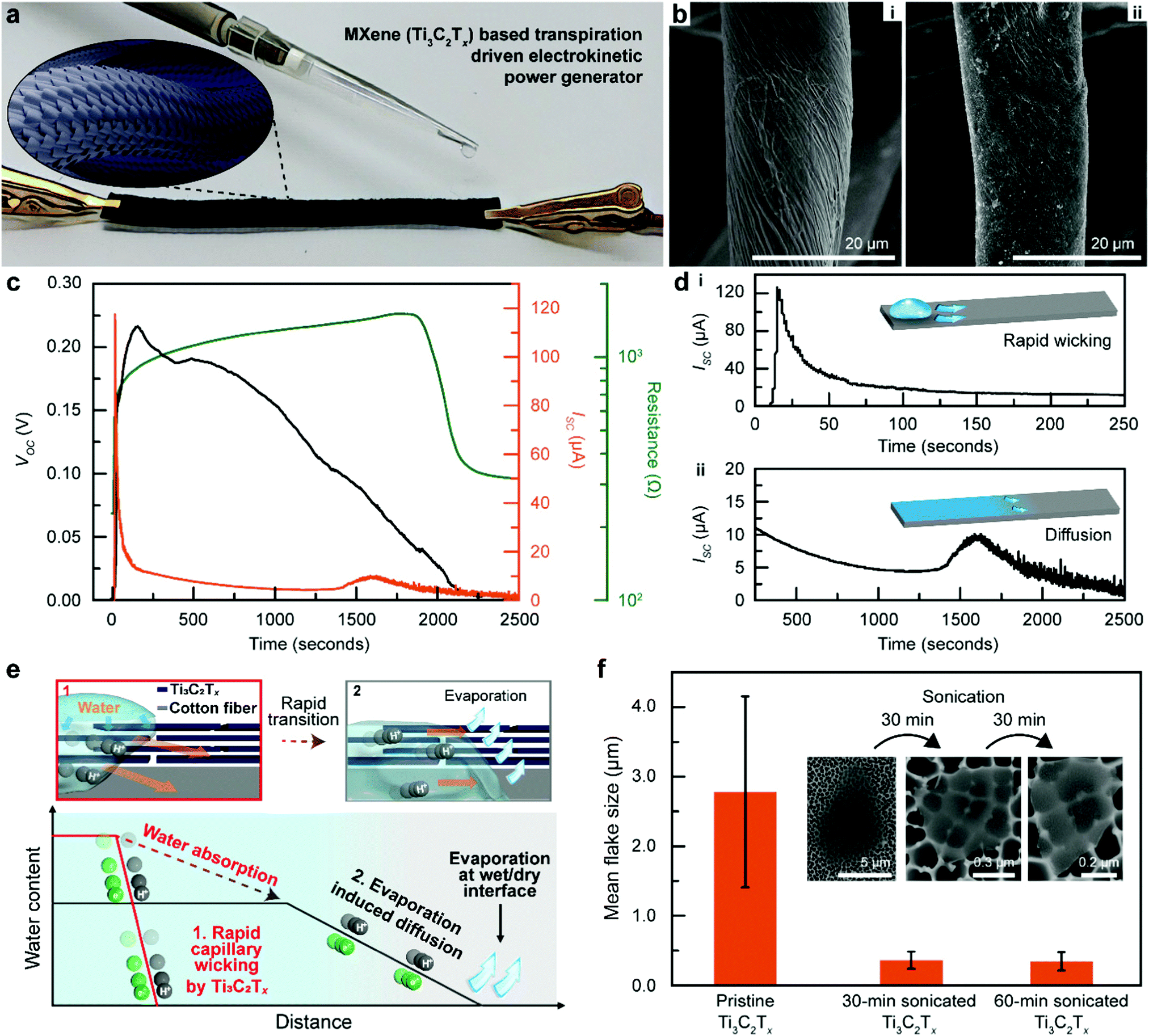 | ||
| Fig. 1 Ti3C2Tx-Based transpiration-driven electrokinetic power generator (MTEPG). (a) Schematic illustration of the energy generation from MTEPG. (b) Scanning electron microscope (SEM) images of MTEPG. i represents that of cotton fibers before coating with Ti3C2Tx nanosheets, and ii represents the fibers fully coated with layered Ti3C2Tx nanosheets on MTEPG. (c) The open-circuit voltage (VOC), short-circuit current (ISC), and resistance profile measured over time by operating the MTEPG (150 Ω) using 30 μL of DI water. (d) Two different pseudo-streaming current behaviours of MTEPG. (i) Rapid wicking drives high electrical current, (ii) moderate-rate wicking due to diffusion and evaporation. (e) Schematic illustration of two different mechanisms ((1) rapid wicking by capillary forces; (2) relatively slow diffusion induced by evaporation) of hydraulic flow through layers of Ti3C2Tx nanosheets. The solid red and grey lines indicate the initial water distribution (1–50 s) and the distribution of water in the steady state (50–2500 s). (f) Tuning the mean flake size of Ti3C2Tx by sonication. | ||
In a typical process, the MXene (Ti3C2Tx)-based TEPG (MTEPG) was fabricated by dipping a piece of cotton fabric (dimension of 0.5 cm × 7 cm × 0.12 mm) in a Ti3C2Tx solution until the entirety of the fabric was soaked, followed by drying at 60 °C to remove the solvent (water) and allow the MXene to adhere onto the fibrous matrix (details in the experimental section). The as-prepared MTEPG device showed a bulk resistance of 150 Ω and, when 30 μL of DI water is pipetted on the negative-electrode side, it could produce a voltage of 0.24 V and a maximum current of 120 μA (Fig. 1c). The resulting current value was 30 times higher, and the power was 35 times higher, respectively, compared to those of the state-of-the-art carbon-based TEPGs (cTEPG).13 The MTEPG also exhibits several interesting properties due to the unique properties of MXene sheets. For one, the magnitude of the resistance change during operation of the MTEPG was 400 times less compared to that of cTEPG, indicating their superior structural integrity based on the van der Waals forces and hydrogen bonds firmly holding the individual Ti3C2Tx nanosheets together.13,35 Moreover, after the application of water, we observed that the resistance of MTEPG continuously increased during the energy generation process (Fig. 1c). This is because of swelling caused by the intercalation of water molecules between MXene layers, which, at equilibrium, is equivalent to about three monolayers of water inserted between each pair of Ti3C2Tx nanosheets.36 Also, after operating the device for one cycle, the bulk resistance of dry MTEPG (i.e., measured after the applied water was fully dried out) increased from 228 Ω to 316 Ω. Since the device was fabricated without any additives or binder molecules (details in the Experimental section), we could attribute the resistance change to the fact that MXene sheets at the outermost layers could detach from the bulk and drift away during the wicking process.13,37 In addition, unmodified Ti3C2Tx MXene nanosheets are vulnerable to oxidation in presence of air and water in the ambient environment (Fig. S3, ESI†).38 As the outermost Ti3C2Tx nanosheets continued to oxidize over long periods of operation, the electrical conductivity of MTEPG was compromised, decreasing the current output (Fig. S4, ESI†). Therefore, future developments should consider the use of oxidation-resistant MXenes with sufficiently high conductivity to develop commercially viable MTEPGs that exhibit long-term stability.31
The mechanism of efficient electrokinetic conversion of Ti3C2Tx
Interestingly, the measured current profile of MTEPG shows a huge peak in the very early stage of operation (Fig. 1c and d), which is far different from the case of cTEPG which does not show an initial peaking behaviour.13 This difference arises from the dissimilar nanoscale hydraulic flow rates that govern the pseudo-streaming current in each material system (Fig. 1e). In detail, the pseudo-streaming current exploits the capillary flow of water through the cotton membrane and thus is proportional to the wicking rate of the water as described in the following equation:| IPST ∝ Qσd | (1) |
To validate our proposed mechanism, we fabricated MTEPGs from Ti3C2Tx nanosheets of different sizes, which we tuned by changing the sonication time, and comparatively studied the relationship between the Ti3C2Tx structure and the Q value of the resulting MTEPG. The mean lateral dimension of as-synthesized Ti3C2Tx was 2.8 ± 1.4 μm, which reduces to 0.36 ± 0.12 μm and 0.34 ± 1.3 μm after 30 min and 60 min of sonication in an ice bath, respectively (Fig. 1f).27 The reduction in the lateral size was also confirmed by XPS, where the portions of peaks that correspond to the amorphous C and C–O bond are increased in high-resolution C 1s and O 1s XPS spectra, respectively (Fig. S5, ESI†). This observation was not a consequence of Ti3C2Tx oxidation, as no observable increase in TiO2 contribution was shown in the Ti 2p spectrum. The amorphous C signals arise mostly from the defective edges of Ti3C2Tx flakes, and thus, the increased contribution of amorphous C indicates a larger edge-to-interior ratio.40,41 Since Ti3C2Tx stacks composed of smaller lateral sizes would provide a larger number of shorter passages for water to penetrate through,39 the Q value was expected to be the highest for the MTEPG based on Ti3C2Tx sonicated for 60 min. Also, it is easier for smaller MXene flakes to infiltrate the cotton fibre membrane, as shown in our previous study.34 In addition, the difference in hydrophilicity and charge may affect the capillary-induced hydraulic flow through the MTEPGs.
To experimentally verify that MTEPGs with smaller Ti3C2Tx domains promote hydraulic flow more effectively, we evaluated the capillary wicking rates of the bare cotton membrane, the surfactant-applied cotton membrane, cTEPG, and MTEPGs (as-synthesized as well as those sonicated for 30 min and 60 min), during which the membranes were hung vertically to prevent the water from leaking out of the membrane (Fig. 2a and Fig. S6, ESI†). The bare hydrophilic cotton membrane exhibited a vertical wicking rate of 0.24 cm s−1. The membrane treated with sodium dodecylbenzene sulfonate (SDBS; anionic surfactant) showed slightly weaker wicking properties (0.22 cm s−1) because the hydrophobic tail of the surfactant would reduce the overall hydrophilicity of the cotton membrane. Interestingly, the cTEPG exhibited a wicking rate of 0.26 cm s−1, which was slightly higher compared to that of the bare and surfactant-treated cotton membranes, showing that the carbon coating layer could function as capillary channels for somewhat enhanced water transportation. Most notably, the MTEPG exhibited high wicking rates of 0.32, 0.51, and 0.85 cm s−1 for as-synthesized, 30-min sonicated, and 60-min sonicated samples, respectively (Fig. 2a). This is consistent with our hypothesis that the layered nanosheet structure of the hydrophilic Ti3C2Tx, would offer an abundance of capillary channels that significantly boost the wicking rate. Also, MTEPG prepared with smaller Ti3C2Tx flakes showed the most efficient wicking because the water would travel a shorter distance through the layered Ti3C2Tx structures. In fact, the MTEPG made of 60 min-sonicated Ti3C2Tx exhibits a 3.5-fold higher wicking rate compared to that of bare cotton. Consequently, we observed that MTEPG having higher values of Q could produce a larger pseudo-streaming current, despite the fact that they are less electrically conductive (Fig. 2b and Fig. S7, ESI†). Specifically, the improved hydrophilicity of the 60-min-sonicated Ti3C2Tx helps to build a larger potential difference. As such, Ti3C2Tx with smaller lateral sizes would exhibit the highest electric power and energy generation efficiency.
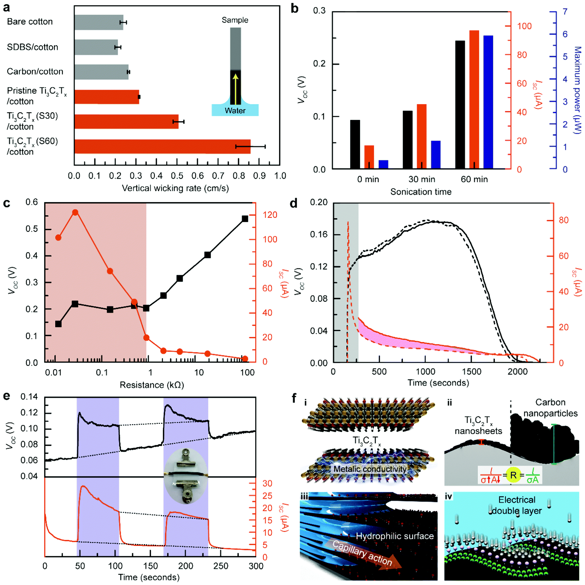 | ||
| Fig. 2 Electrokinetic behaviour of Ti3C2Tx on MTEPG. (a) Vertical wicking rate of cotton membranes, cTEPG, and MTEPG with different flake sizes. (b) Energy generation performance of MTEPGs made of different flake size of Ti3C2Tx. (c) Measured VOC and ISC values from the MTEPG as a function of bulk resistance. (d) Measured VOC and ISC profiles starting from water-dropping (dotted line) and 2 min after water dropping (solid line). The pink region is the charge amount accumulated in the open-circuit condition for the first 2 min, which was calculated to be about 3.79 mC. This value matches with that of the estimated total charge in the non-delayed condition (3.84 mC), which is equivalent to the area under the curve in the gray region. (e) Measured VOC and ISC values from the MTEPG with pressurization (blue region) and without pressurization (white region). Even after repeat cycles, the VOC and ISC values do not deviate much from the approximated values of MTEPG in the non-pressurized state, as indicated by the dotted line, suggesting that the microstructure of MTEPG was retained in repeated pressurization processes. (f) Merits of MXene as an electrokinetic converting material. (i) Metallic conductivity, (ii) nanosheet morphology, (iii) hydrophilicity, (iv) excellent double layer formation. | ||
Altogether, we may understand the mechanism for power generation in MTEPG in two parts. First, the efficient wicking process through the Ti3C2Tx layer of the MTEPG is responsible for the high current peak (120 μA) in the initial stage of the operation. After the initial intense electrokinetic interaction, the current is subsequently generated by the water content gradient at the wet/dry interface (Fig. 1d-ii). Since the maximum water content of the cotton membrane limits the water gradient, the diffusive hydraulic flow would be relatively slower than in the initial wicking process, resulting in a moderate yet continuous pseudo-streaming current of 5–10 μA. Notably, the small bump was observed at the end of the operation (after ∼1600 s). During this final drying stage, the diffusion rate would be continuously reduced by decreasing water content. However, since the distance between Ti3C2Tx layers decreased due to the removal of intercalated water molecules, the resistance of the device got decreased, reducing Ohmic loss and slightly increasing the measured current.
High energy performance of MTEPG
The voltage/current trade-off relationship of TEPGs, in general, depends on their bulk resistance (Fig. 2c and Fig. S8, ESI†).3,13 In MTEPG, we could observe a threshold bulk resistance value of about 2 kΩ that separates the voltage and current trends into two different regimes. Below 2 kΩ, as the resistance decreases, the current increases dramatically while the voltage remains around 0.2 V. Above 2 kΩ, the voltage increases gradually, whereas the current decreases slightly. Overall, since the current governs the electric power generation performance, the maximum power was recorded in the low-resistance regime (Fig. S9, ESI†). However, it should be noted that the MTEPG with the lowest bulk resistance (< 5 Ω), containing the largest amount of Ti3C2Tx, showed less than ideal power generation performance. In this situation, the layer-by-layer alignment of Ti3C2Tx nanosheets would be reduced, weakening the lateral capillary flow along with cotton fiber (Fig. S10, ESI†). Altogether, we found that the adequately conductive MTEPG (27 Ω) exhibits the highest current (120 μA) and electric power (6.6 μW), significantly outperforming the previously demonstrated cTEPG (250 nW).13The high electron mobility of Ti3C2Tx facilitates pseudo-streaming current at the wet/dry boundary of MTEPG, where the steepest electrical potential gradient exists. To understand the electrokinetic phenomena at the boundary, we intentionally left the MTEPG in the open circuit condition and delayed the measurement, allowing the electrokinetically transported electrons to accumulate at the wet/dry boundary. When the electrical circuit is subsequently formed, the accumulated electrons would flow at once, contributing to the overall current and appearing as a surplus on the current profile compared to that of normal measurement. The current profiles of MTEPG after a 2-min delay showed an excess current equivalent to that of 2.87 mC of total change transferred (the pink region in Fig. 2d), which is a 9-fold higher value than that of cTEPG (Fig. S11, ESI†). The massive electron accumulation on the MTEPG serves as evidence that (1) Ti3C2Tx produces a large amount of water-induced electron flow, (2) Ti3C2Tx has a sufficient capacity for charge storage, and (3) the electrons travel across the potential gradient at the wet/dry border of MTEPG with relative ease. In terms of the voltage profile, there is little difference between the normal and delayed measurements, which is unlike the behaviour for cTEPG.3 This indicates that the scattering of electrons at the electric double layer has been significantly suppressed in MTEPG compared to cTEPG, suggesting that Ti3C2Tx exhibits better electrical, chemical, and structural integrity than carbon-based materials.
To further improve the structural integrity, electrical contact, and interfacial electrokinetic behaviours, we pressurized the MTEPG by applying compressive mechanical stress, a conventionally used approach to improve packaging density.42,43 As shown in the inset of Fig. 2e, we placed the MTEPG between two glass substrates with binding clips holding each of the ends together. The pressurization process reversibly enhances the voltage about 2-fold and the current about 3-fold, which is attributed to the improved contact between Ti3C2Tx nanosheets and the cotton membrane upon pressurization (Fig. 2e). Another contributing factor is that the extraneous water stored at the core of the cotton fabric, not contributing to the power generation, is mechanically squeezed out of the fabric matrix to allow the remaining water to be utilized more efficiently at the Ti3C2Tx layers. Altogether, we demonstrated that the packaging of MTEPG is as crucial as the material selection with regards to the rational design of practical nano-hydroelectric generators.
Based on all of these findings, we argue that the excellent electrokinetic performance of MTEPG originates from the advantageous intrinsic properties of Ti3C2Tx (Fig. 2f). First, Ti3C2Tx provides excellent electrical conductivity even in a nanoscale domain, which is crucial for improving the electrokinetic conversion efficiency and reducing the Ohmic loss during the energy generation process (Fig. 2f-i). While the minimum bulk resistance for cTEPG was 10 kΩ, MTEPG could achieve bulk resistance down to 15 Ω, a 666-fold improvement in conductivity. In addition, the nanosheet feature reduces the overall distance between Ti3C2Tx and the cotton membrane to minimize dead space, facilitating a more efficient electrokinetic interaction between Ti3C2Tx and water (Fig. 2f-ii). Moreover, the layered structure of the hydrophilic Ti3C2Tx promotes the nanoscale-hydraulic flow with the assist of capillary action (Fig. 2f-iii). Finally, Ti3C2Tx exhibits a high ionic affinity, which leads to the facile and spontaneous formation of an electrical double layer on the surface (Fig. 2f-iv).44 Altogether, owing to its advantageous nanoscale, electrical, morphological, and chemical properties, Ti3C2Tx MXene is well-suited as an electrokinetic converting material for TEPG. Moreover, pure MXene fibers with flakes aligned along their length have been reported45 and may offer a further significant reduction in conductivity. Taking into account that titanium and carbon are among the most common earth-abundant elements, scalable manufacturing of TEPG using Ti3C2Tx is an achievable target, especially considering that the expansion of the life-time of Ti3C2Tx in solution to about a year, provided that a stoichiometric structure is produced.31
Amplified electric power by electrolytes
Since ions play a crucial role in the energy generation mechanism, previous designs of TEPGs often involved the utilization of electrolyte-containing water to amplify the generated electrical energy.3,13 To assess whether the same mechanism would be applicable for MTEPGs, we investigated the electrokinetic interactions between Ti3C2Tx and various conventional electrolyte solutions. In particular, cations intercalate between MXene layers either by forming a large solvation shell (hydrophilic cations like Mg2+) or by pushing water out of the interlayer volume (less hydrophilic cations like Cs+).46 Their charge storage behaviour depends on their size, charge, and solvation energy.47 For chloride salts of alkali (monovalent) or alkaline earth (divalent) elements, the one with a smaller cationic radius produced a higher voltage and current, consistent with the typically elucidated energy generation mechanism involving double layers (Fig. 3a and Fig. S12, ESI†). Besides, Mg2+ ions have been reported to have a specific interaction with Ti3C2Tx MXene that could stabilize ionic adsorption in multi-layered MXene.48,49 For example, the voltage and current were amplified up to 0.55 V and 2.28 mA by using the NaCl solution on the MTEPG (150 Ω), which is equivalent to a 2.5-fold and a 19-fold enhancement in the voltage and current, respectively, compared to the case of using DI water. The improvement in the current generation is attributed to the additional number of metal ions participating in the charge transport through the layered Ti3C2Tx structure, as well as the high affinity of Ti3C2Tx to metal ions.44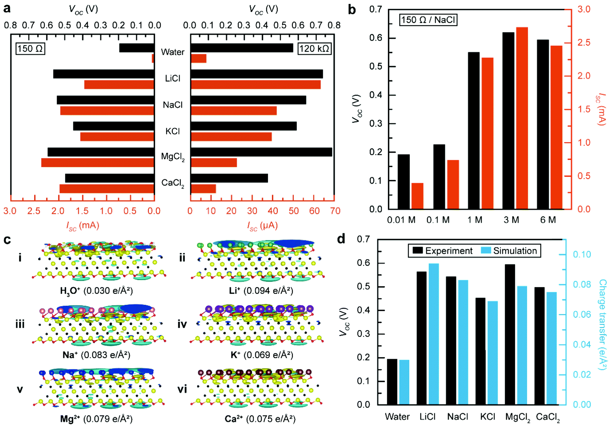 | ||
| Fig. 3 Effect of electrolyte on energy generation from MTEPG. (a) Measured VOC and ISC values from the MTEPG (150 Ω and 120 kΩ) with various electrolyte solutions (1 M). (b) Measured VOC and ISC values from the MTEPG (150 Ω) with NaCl solutions of various concentrations. (c) Charge redistribution on Ti3C2Tx covered by hydronium ions only (i), hydronium ions with lithium ions (ii), sodium ions (iii), potassium ions (iv), magnesium ions (v), calcium ions (vi). The value of the electron redistribution on Ti3C2Tx is listed below each panel. (d), Comparing the measured voltage and the calculated charge transfer. | ||
Furthermore, we conducted a series of control experiments using MTEPG with fewer layers of Ti3C2Tx, which exhibits a higher resistance value (120 kΩ), while maintaining identical conditions otherwise (Fig. 3a and Fig. S12, ESI†). Although the overall voltage was measured to be higher in the 120 kΩ MTEPG compared to that of the 150 Ω MTEPG, the electrolyte-induced enhancements in the voltage were far less compared to the case of the 150 Ω MTEPG. Likewise, the electrolyte-induced enhancement in the current for the 120 kΩ MTEPG was only 6-fold compared to the case of DI water, which is far less than that of the 150 Ω MTEPG (35.4-fold). Notably, the salt solutions of divalent cations (MgCl2 and CaCl2) produced far smaller current values using the 150 Ω MTEPG compared to that of the 120 kΩ MTEPG, which can be attributed to the sluggish capillary wicking of the alkaline solution through the cotton membrane due to partial hydrolysis reaction50,51 (Fig. S13, ESI†). Because divalent ions readily intercalate the layered MXene films,44 the higher current generated by the divalent ionic solution on highly conductive MTEPG (150 Ω) could be ascribed to the additional charge storage between MXene layers due to multilayer adsorption and intercalative ion transport through the layered film of Ti3C2Tx.49
It should be noted that, while using a more concentrated NaCl solution leads to a higher voltage and current, this trend holds true only until 1 M, above which the improvement shows a diminishing return and eventually reaches saturation (Fig. 3b and Fig. S14, ESI†). In environments with high ion concentration, the Debye screening length becomes shorter, which hinders intercalative diffusion of cations into layered MXenes.52 As shown in Table 1, the high-resistance MTEPG (120 kΩ) exhibited the highest voltage value (0.64 V) but with a relatively poor current (41.9 μA) (Fig. S15, ESI†). In contrast, the low-resistance MTEPG (150 Ω) delivered the highest current value (2.28 mA) with a moderate voltage value (0.55 V). Therefore, we could conclude that the MTEPG with lower electrical resistance is advantageous for generating high electric power when combined with an appropriate electrolyte solution.
| Resistance | Water | NaCl solution | Enhancement |
|---|---|---|---|
| Voltage | |||
| 150 Ω | 0.198 V | 0.55 V | 178.3% |
| 120 kΩ | 0.57 V | 0.64 V | 12.8% |
| Current | |||
| 150 Ω | 64.0 μA | 2.28 mA | 3462% |
| 120 kΩ | 7.72 μA | 41.9 μA | 443% |
Considering these findings, we found that seawater, an easily accessible and abundant source of water with an adequate concentration of NaCl, could serve as an excellent electrolyte for MTEPG operation, offering a sufficiently high voltage of 0.34 V and a current level of 1.35 mA (Fig. S16, ESI†). Moreover, we found that the salt solution can also be repeatedly applied to the MTEPG device for their continuous operation (Fig. S17, ESI†).
To understand the mechanism behind the enhanced voltage output when electrolytes are involved, specifically in the context of MXenes, we used density functional theory (DFT) calculations to evaluate the surface charge density in the electrical double layer formed by the adsorption of water molecules and metal cations on the Ti3C2Tx basal surface (details in the Experimental section).3,14,47 When Ti3C2Tx is covered only by water molecules, a water double layer forms at the water/Ti3C2Tx interface with a surface charge density of 0.030 e Å−2 (Fig. 3c-i). In comparison, the surface charge density increases to 0.094 e Å−2 when Li+ ions are additionally attached to the surface (Fig. 3c-ii). In general, the metal cations contribute additional charges at the outer Helmholtz layer, increasing the overall surface charge density on Ti3C2Tx and the measured voltage (Fig. 3c). In the end, the total charge transfer as per the DFT calculations is in good agreement with experimental results, supporting our understanding of the role of metal cations (Fig. 3d).
Synergistic effect of Ti3C2Tx and polyaniline
Having established that the improved diffusion kinetics of Ti3C2Tx contributed to a significant enhancement in the power generation performance, a rational design was considered by adding polyaniline, a conductive polymer that provides an ionic diffusive channel when combined with 2D materials,53 to maximize the power generation efficiency of the MTEPG. It should be noted that the insulative emeraldine-base form was used instead of the conductive emeraldine-salt form to avoid complications with analyzing electrical measurements. Specifically, polyaniline was mixed with aqueous Ti3C2Tx ink in various mass ratios (Ti3C2Tx:polyaniline = 1:0, 10:1, 4:1, 2:1, 1:1, 1:2, 1:4, or 1:10) to fabricate Ti3C2Tx/polyaniline-based TEPG (MPTEPG) (Fig. 4a). As shown in Fig. 4b, polyaniline was well dispersed in-between the Ti3C2Tx layers. Interestingly, the MTEPGs and MPTEPGs fabricated with the same concentration of Ti3C2Tx ink possess similar bulk resistances up to the Ti3C2Tx:polyaniline mass ratio of 1:4 (Table S1, ESI†). The bulk resistance of dry MPTEPG showed little change even after adding insulative polyaniline, which can be explained by the partial protonation of intercalated emeraldine-base polyaniline to form emeraldine-salt polyaniline, which is conductive (Fig. S18, ESI†). Moreover, during the operation with DI water, the resistance of MPTEPG was lower by 2.68 times compared to that of MTEPG, showing that polyaniline effectively supports the electrical network of MPTEPG (Fig. S19, ESI†). When the Ti3C2Tx:polyaniline mass ratio was around 1:1, the MPTEPG exhibited a voltage of 0.56 V and a current of 37 μA in DI water, which is a 3.8-fold enhancement in terms of the power compared to that of the MTEPG (Fig. 4c, d and Fig. S20, ESI†). Furthermore, we also investigated the effect of bulk resistance on energy performance using the MPTEPG (1:1 mass ratio; Fig. 4e and Fig. S21, ESI†) and showed that the voltage value saturated above 0.2 kΩ, whereas the current exhibited a linear decrease on a logarithmic scale (Fig. 4e). As a result, the optimal resistance value for achieving the maximum power shifted from 150 Ω to 220 Ω, which implies that MPTEPG requires a smaller amount of Ti3C2Tx compared to the case of MTEPG in order to maximize the electric power (Fig. 4f). Since the conductivity of polyaniline is much smaller than that of Ti3C2Tx, it could be concluded that the synergy between Ti3C2Tx and polyaniline originates from the improved ionic transport.
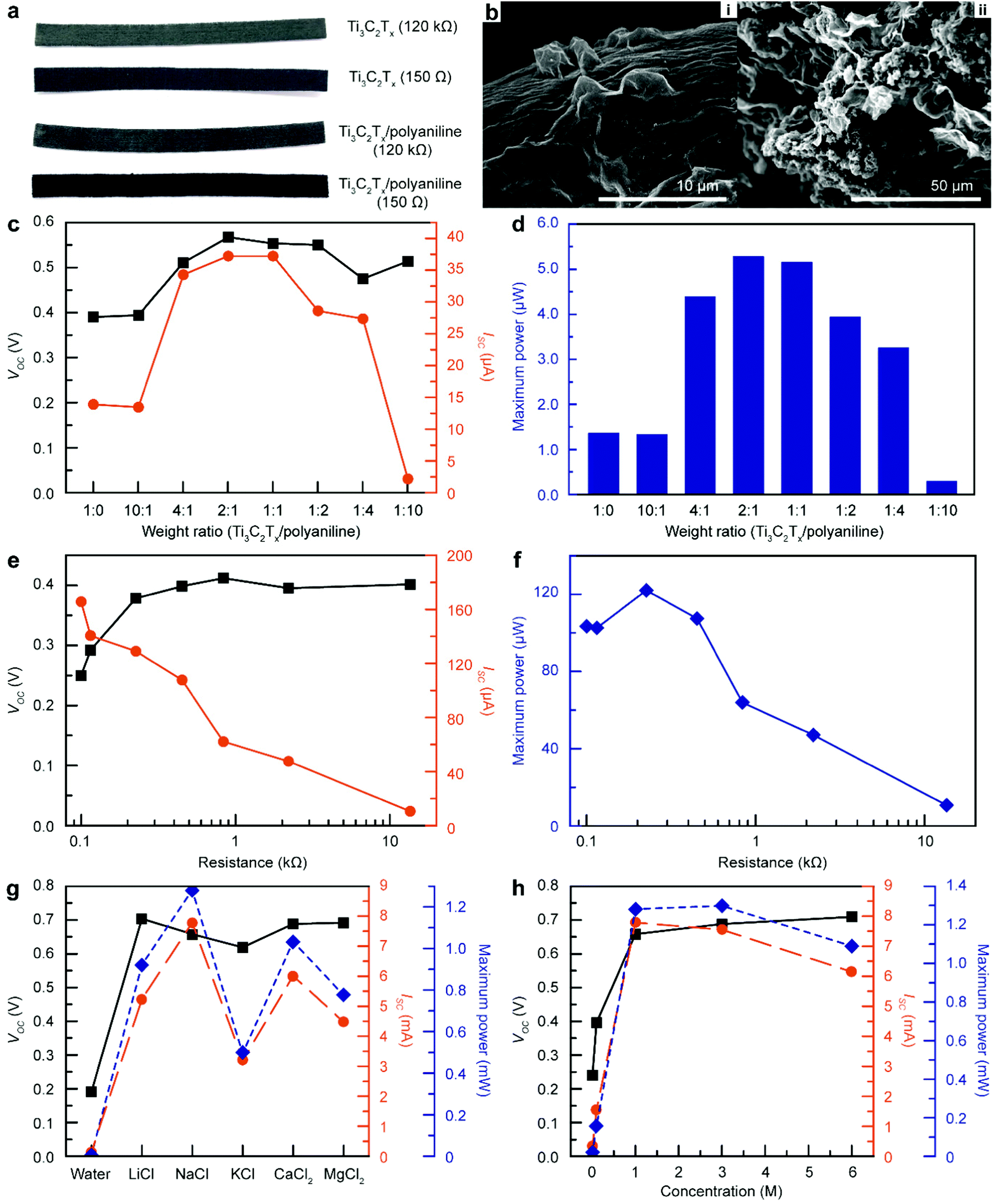 | ||
| Fig. 4 Energy generation performance of Ti3C2Tx/polyaniline-based TEPG (MPTEPG). (a) Photographic images of MTEPG and MPTEPG with the resistances of 150 Ω and 120 kΩ. (b) SEM images of MPTEPG. i and ii are a front view and a cross-sectional view of Ti3C2Tx/polyaniline-coated cotton fiber, respectively. (c) Measured VOC and ISC values from the MPTEPG (250 Ω) with various polyaniline contents. (d) Measured power from the MPTEPG (250 Ω) with various polyaniline contents. (e) Measured VOC and ISC values from the MPTEPG with various bulk resistance. (f) Generated power from the MPTEPG (weight ratio 1:1, 250 Ω) as a function of bulk resistance. (g) Measured VOC, ISC, and power values from the MPTEPG (weight ratio 1:1, 250 Ω) with various electrolyte solutions (1 M). (h) Measured VOC, ISC, and power values from the MPTEPG (weight ratio 1:1, 250 Ω) with NaCl solution of various concentrations. | ||
To investigate the ion-diffusive properties of polyaniline also in the presence of foreign ionic species, we conducted electrical measurements on MPTEPG upon applying various electrolyte solutions (Fig. 4g and Fig. S22, ESI†). Similar to the results for MTEPG, the MPTEPG also showed an improvement in the voltage output by 0.1 V when a salt solution was used instead of DI water. However, we could not identify an explicit trend in the voltage and current as a function of the ionic radii of the electrolyte salts, unlike the cases of MTEPG and cTEPG.13 This behaviour is attributed to the specific cation-polyaniline interactions, such as the high permeability of K+ in the polyaniline matrix.54–56 Nevertheless, this result suggests that a multi-electrolyte solution, such as seawater, could further maximize the energy generation efficiency even for multi-component electrokinetic converting materials. Very importantly, the pseudo-streaming current produced by a NaCl solution in MPTEPG exceeds 7.8 mA, which is a 4-fold enhancement compared to that of MTEPG and 791-fold compared to that of cTEPG. Of the experimental conditions that we evaluated, the MPTEPG (250 Ω) operating with a NaCl solution produced the highest electric power (1.3 mW). Specifically, the NaCl solution with concentrations in the range of 1 to 3 M produced the highest electric power, while the saturated NaCl solution was practically inadequate due to its poor wetting on a cotton membrane (Fig. 4h and Fig. S23, ESI†). The optimized MPTEPG exhibited a maximum voltage of 0.69 V, current of 7.55 mA, power of 1.3 mW (equivalent to a specific power density of 30.9 mW cm−3), and specific energy density of 0.114 W h cm−3 when operated with 30 μL of 3 M NaCl solution, which is by far the highest energy performance in comparison with all previous reports on nano-hydroelectric generators (Table S2, ESI†). As an additional demonstration, the MPTEPG could generate 0.54 V and 4.63 mA with 30 μL of seawater (Fig. S24, ESI†). Taken together, these results suggest that the polyaniline incorporated into Ti3C2Tx matrix provides effective ionic transport channels and supports the enhanced power generation by aqueous electrolyte solutions.
Demonstration of the practicality of MPTEPG
Owing to the improved energy performance by the integration of Ti3C2Tx and polyaniline, the number and volume of MPTEPG devices required to illuminate a blue LED or even to charge a battery was greatly minimized compared to cTEPG (Fig. 5a). Only 24 MPTEPG units were needed to light up a blue LED (rated voltage of 3.2 V and current of 20 mA), whereas 41000 cTEPG units were required to generate the same amount of power. As shown in the inset of Fig. 4a and Video S1 (ESI†), the MPTEPG could stably operate a blue LED with six piles of devices in serial connection, where each pile consisted of four units in parallel connection (total volume of 6.05 cm3). Notably, this setup is ten times smaller in overall device volume compared to that of a cTEPG network required to light up a red LED, which requires much less energy to operate than a blue LED.13 In another case study, the charging rate of commercialized supercapacitor (1 F) by the MPTEPG was 3 times faster compared to a cTEPG with the same volume (Fig. 5b). Finally, as the first demonstration of its kind, we used 160 units of MPTEPG to charge a commercial battery (135 mW h, the input source of 5 V, 1 A) from 19% to 33% of its full capacity in 20 min by using seawater (Fig. 5c and Video S2, ESI†). We believe that this breakthrough accomplishment serves as a major milestone in the development of practical nano-hydroelectric generators for powering devices for Internet of things applications and other electronics.
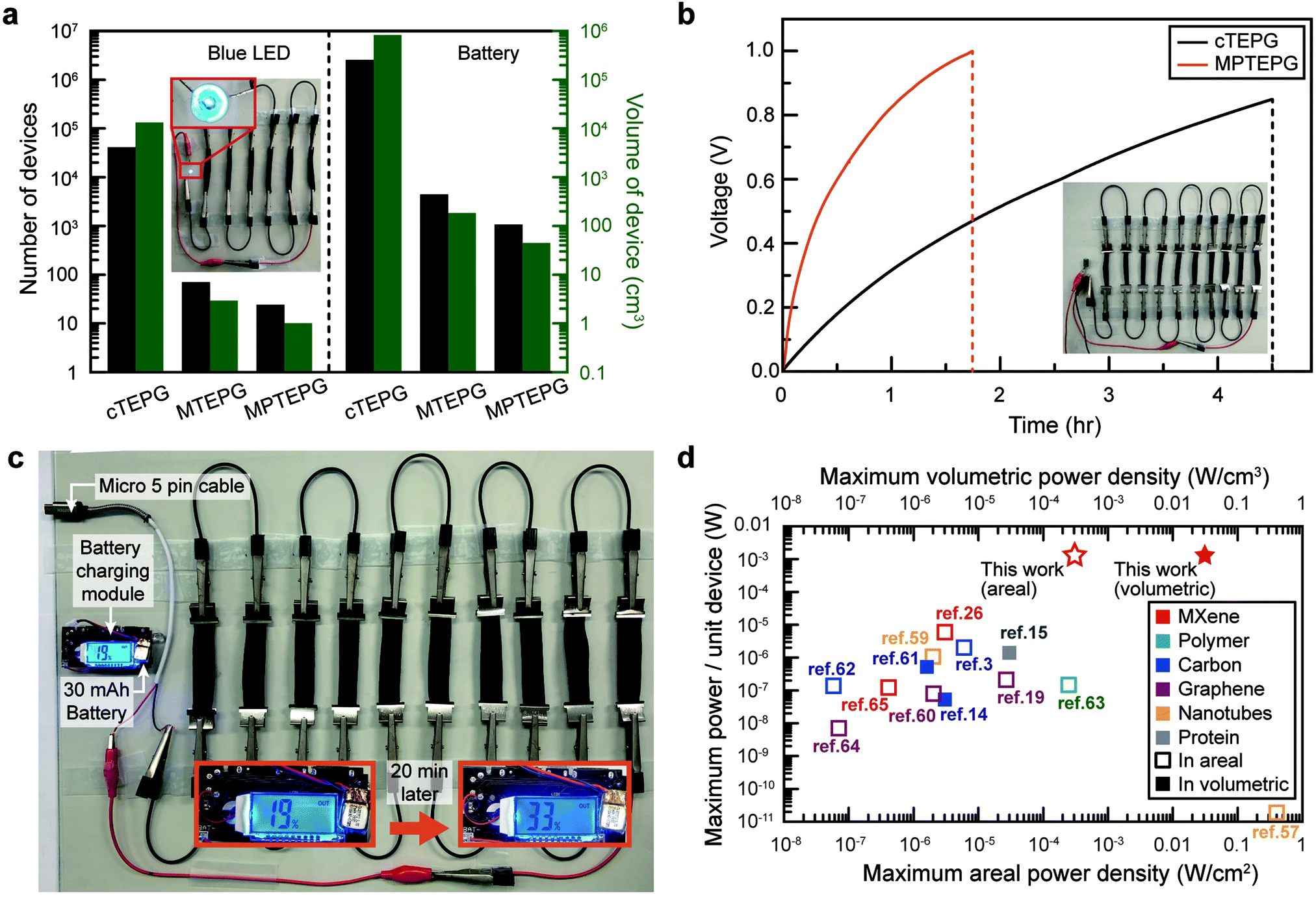 | ||
| Fig. 5 Operation of various electronic devices by the scaled-up MPTEPGs. (a) Logarithmic plot of the required number and volume of TEPGs to operate a blue LED and a commercial battery. Inset: photographic image of lightening blue LED (rated input voltage: 3.2 V, rated input current: 20 mA) by using 6 devices connected in series with 4 parallel MPTEPG and wetted by seawater. (b) Charging graph of a commercial 1 F supercapacitor by the same volume of MPTEPG and cTEPG, respectively. (c) Charging a commercialized battery (30 mA h; rated input voltage: 5 V, rated input current: 1 A) from 19% to 33% within 20 min by using devices connected in series (16 parallel layers in each – 160 MPTEPGs total). (d) Performance comparison between various nano-hydroelectric generators made of different electrokinetic converting materials, in terms of the maximum possible power output of a single unit device with respect to the areal and/or volumetric power densities. | ||
Conclusions
We successfully designed and manufactured transpiration–driven electrokinetic power generators using Ti3C2Tx MXene and Ti3C2Tx/polyaniline composite on cotton (MPTEPG), which exhibit significantly improved energy generation efficiency and achieved an unprecedented energy performance (0.69 V, 7.55 mA, and 1.3 mW). In particularly, the power output was improved from the μW range to the practically relevant mW range. High electrical conductivity, intrinsic hydrophilicity, and 2D structure of Ti3C2Tx altogether facilitate a more rapid capillary flow and enhance the pseudo-streaming current. Moreover, it also offers a high cationic affinity due to a large negative charge on its surface, which can induce a high potential difference. An adequate selection of electrolytes and ion-conductive polymers, such as polyaniline, further improved the energy conversion efficiency of MPTEPG. Since the energy produced in nano-hydroelectric generators does not scale proportionally to their volume14,57 (Fig. 5d3,14,15,19,21,26,58–67), the low energy output per unit device hampered practical applications of nano-hydroelectric generators. The manufactured composite MPTEPG with 160 units in the module reaches an electric power output of 208 mW, signaling the transition of the TEPG technology from lab-scale discovery to a practically viable solution for renewable energy. The energy generation performances of MXene-based nano-hydroelectric energy harvesting devices can be further optimized through strategies such as modifying surface functional groups on the MXenes,68–70 modulating the interlayer spacing to transition the MXenes into the liquid crystal phase with higher diffusivities,45,71 and protecting the MXenes against oxidation in air using gas filtration layers.72,73Experimental section
Synthesis of Ti3C2Tx MXene nanosheets
Ti3C2Tx MXene was synthesized by the Minimally Intensive Layer Delamination (MILD) method.74 4.8 g of lithium fluoride (Alfa Aesar, LiF 98.5%, 325 mesh powder) was dissolved into 60 mL of 9 M HCl (Sigma Aldrich, ACS reagent 37% diluted with DI water) solution in a polypropylene bottle, and the solution was magnetically stirred for 5 min at 35 °C. 3.0 g of Ti3AlC2 (Jilin 11 Technology Co., Ltd) was then slowly added to the solution over 5 min while stirring. The suspension was incubated at 35 °C for 24 h with magnetic stirring at 300 rpm. After the reaction, the suspension was transferred to 250 mL polypropylene centrifuge bottles and washed with DI water several times until the pH reaches 6–7 by repeated centrifugation (typically twice at 3500 rpm for 5 min and 3–4 times at 8000 rpm for 20 min). After washing, the sediment of the last centrifugation was transferred to few 50 mL conical tubes (Falcon) after suspended in DI water. Then, the delaminated mono- or few-layer Ti3C2Tx flakes were separated from the heavier impurities such as unreacted reactants (LiF or Ti3AlC2) by collecting the supernatant from centrifugation at 1000g for 20 min. Finally, the few-layer Ti3C2Tx colloid was concentrated (∼50 mg ml−1) by centrifugation. The resulting Ti3C2Tx slurry was kept in Ar-purged vials. For MXene flakes of reduced lateral sizes, the Ti3C2Tx in the Ar-purged vials were sonicated in an ice bath for 30 or 60 min.Materials characterization
A Hitachi Regulus 8230 SEM was used for visualizing the monolayer MXene flakes and measuring their lateral sizes (over 150 flakes). The conductivity measurement and XPS analysis (PHI 5000 VersaProbe, ULVAC PHI) were carried out on freestanding films formed by vacuum filtration.Fabrication of MTEPG and MPTEPG
0.0283 g ml−1 aqueous solution of Ti3C2Tx was produced by diluting the Ti3C2Tx slurry and used for infiltration. The cotton fabric (0.5 cm × 7 cm × 0.12 cm, provided by Amore Pacific, Inc.) was immersed into Ti3C2Tx for 5 s and dried at 60 °C for 20 min to fabricate an MTEPG. The loading amount can be added further by multiplying the immersion/drying cycles.75 The resistance values reported in this manuscript, unless stated otherwise, refer to the resistance values measured from the entire (M)TEPG device from end to end, respectively, which ranges from 10 Ω ∼ 500 kΩ. By minimizing the lateral size of the generator, we could reduce the amount of water to operate an MTEPG from 0.25 mL (cTEPG)13 to 30 μL with the same operation time. In this way, the fuel efficiency increased from 1.4 × 10⁻³ W h L−1 to 5.2 × 10⁻² W h L−1. The resistance of MTEPG was controlled by varying the number of dip-coatings and concentration of the dipping solution. As the properties of laboratory-produced Ti3C2Tx were slightly different in each batch, the concentration of the dipping solution was adjusted for each experiment. For fabricating MPTEPG, the polyaniline emeraldine base powder (Sigma Aldrich, Mw 10000) was mixed into the Ti3C2Tx solution in a range of mass ratios listed in Table S1 (ESI†). Likewise, cotton fabric was immersed in the Ti3C2Tx/polyaniline ink and then dried at 60 °C for 20 min to fabricate the MPTEPG device. The open-circuit voltage and the short-circuit current of the TEPGs were each measured separately by an electrometer (6517A, Keithley) under 50% relative humidity. Electrical power or power density values were calculated from the open-circuit voltage and short-circuit current, since the MTEPG exhibit an ohmic contact behaviour in I–V curves (Fig. S25, ESI†).
Illuminating a blue LED and charging energy storage system by MPTEPG with seawater
For the evaluation of the energy performance of MPTEPG, blue LED (the rated voltage of 3.0–3.2 V and current of 20 mA) was operated by an MPTEPG assembly consisting of six piles in serial connection, where each pile consisted of four MPTEPG units in parallel connection, using 0.9 mL of seawater without an electrical modifier (Fig. 5a). A commercial supercapacitor (SAMXON, 1 F) was charged to 1 V by using 10 series connections of 6 parallel MPTEPGs with 3 mL of seawater (Fig. 5b). A lithium–polymer battery (TW 401012, 30 mA h, 3.7 V) was charged from 19% to 33% in 20 min using 10 series connections of 16 MPTEPGs connected in parallel, with 10 mL of seawater (power output stabilized within 5 min, retained over 30 min). The charging was performed through an Arduino-based battery charging module (rated charging voltage of 5 V and current of 1 A, Fig. 5c).DFT calculations for charge redistribution on Ti3C2Tx
All calculations were performed at the density functional theory (DFT)76 level using the Vienna ab initio simulation package (VASP)77 based on the plane-wave basis set to describe the charge transfer behaviours of cations on the surface of the Ti3C2Tx structure. The electron-core interaction was expressed by the projector augmented wave method (PAW).78 The gradient-corrected exchange–correlation and general gradient approximation function of Perdew–Burke–Ernzerhof (PBE)79 was applied for all calculations. A kinetic energy cut-off of 500 eV was imposed for the plane-wave basis set, and Γ-point sampling was used for the Brillouin zone integration. In order to avoid the interactions between periodic configurations along the axis perpendicular to the surface, all slabs are separated by 20 Å along the direction perpendicular to the surface. Materials Studio80 was used to generate the initial structures. From these initial configurations, DFT simulations were conducted to optimize the structures. For a direct comparison of numerical values for charge transfer between the metal cations and Ti3C2Tx, charge partitioning was performed with the Bader81 methods implemented in VASP75 and provided by the BADER tool.81Author contributions
J. B. conceived the idea and designed the project. J. B. and M. S. K. conducted the overall experiment and characterization and analyzed the results. J. B. and M. S. K. wrote the manuscript. Under the supervision of C. M. K., T. O. and S. L. synthesized and characterized Ti3C2Tx MXene. Under the supervision of K. H., B. L. S. carried out DFT calculations. I.-D. K. and Y. G. supervised the project. All authors discussed the results and reviewed the manuscript.Conflicts of interest
There are no conflicts to declare.Acknowledgements
We acknowledge Prof. Reginald M. Penner at UC Irvine and Dr Jaewan Ahn at KAIST for helpful discussion. This work was supported by the Samsung Research Funding & Incubation Center of Samsung Electronics under Project Number SRFC-MA1802-05 and KAIST Institute for the NanoCentury. This work was further supported by the National Research Foundation of Korea (NRF) grant funded by the Korea government (MSIT) (No. 2021R1C1C2006535 and 2020M3H4A3106354) and the Korea Institute of Science and Technology (No. 2E30250). Collaboration with Drexel University was supported by the NRF Global Research and Development Center Program (NNFC-Drexel-SMU FIRST Nano Co-op Centre, 2015K1A4A3047100).Notes and references
- P. Kamalinejad, C. Mahapatra, Z. Sheng, S. Mirabbasi and V. C. M. Leung, IEEE Commun. Mag., 2015, 53, 102–108 Search PubMed.
- X. Liu, Z. Qin, Y. Gao and J. A. McCann, IEEE Internet Things J., 2019, 6, 4935–4945 Search PubMed.
- J. Bae, T. G. Yun, B. L. Suh, J. Kim and I. D. Kim, Energy Environ. Sci., 2020, 13, 527–534 RSC.
- K. Zhang, S. Wang and Y. Yang, Adv. Energy Mater., 2017, 7, 1601852 CrossRef.
- Y. Ji, K. Zhang and Y. Yang, Adv. Sci., 2018, 5, 1700622 CrossRef PubMed.
- Z. L. Wang, Adv. Funct. Mater., 2008, 18, 3553–3567 CrossRef CAS.
- Y. Su, Y. Yang, X. Zhong, H. Zhang, Z. Wu, Y. Jiang and Z. L. Wang, ACS Appl. Mater. Interfaces, 2014, 6, 553–559 CrossRef CAS PubMed.
- T. Quan, Y. Wu and Y. Yang, Nano Res., 2015, 8, 3272–3280 CrossRef CAS.
- A. K. Jena, A. Kulkarni and T. Miyasaka, Chem. Rev., 2019, 119, 3036–3103 CrossRef CAS PubMed.
- D. P. McMeekin, G. Sadoughi, W. Rehman, G. E. Eperon, M. Saliba, M. T. Hörantner, A. Haghighirad, N. Sakai, L. Korte, B. Rech, M. B. Johnston, L. M. Herz and H. J. Snaith, Science, 2016, 351, 151–155 CrossRef CAS PubMed.
- J. Qi, N. Ma and Y. Yang, Adv. Mater. Interfaces, 2018, 5, 1701189 CrossRef.
- X. Wang, S. Niu, Y. Yin, F. Yi, Z. You and Z. L. Wang, Adv. Energy Mater., 2015, 5, 1501467 CrossRef.
- T. G. Yun, J. Bae, A. Rothchild and I. D. Kim, ACS Nano, 2019, 13, 12703–12709 CrossRef CAS PubMed.
- G. Xue, Y. Xu, T. Ding, J. Li, J. Yin, W. Fei, Y. Cao, J. Yu, L. Yuan, L. Gong, J. Chen, S. Deng, J. Zhou and W. Guo, Nat. Nanotechnol., 2017, 12, 317–321 CrossRef CAS PubMed.
- X. Liu, H. Gao, J. E. Ward, X. Liu, B. Yin, T. Fu, J. Chen, D. R. Lovley and J. Yao, Nature, 2020, 578, 550–554 CrossRef CAS PubMed.
- T. Xu, X. Ding, Y. Huang, C. Shao, L. Song, X. Gao, Z. Zhang and L. Qu, Energy Environ. Sci., 2019, 12, 972–978 RSC.
- Z. Zhang, X. Li, J. Yin, Y. Xu, W. Fei, M. Xue, Q. Wang, J. Zhou and W. Guo, Nat. Nanotechnol., 2018, 13, 1109–1119 CrossRef CAS.
- Q. Li, M. Zhou, Q. Yang, M. Yang, Q. Wu, Z. Zhang and J. Yu, J. Mater. Chem. A, 2018, 6, 10639–10643 RSC.
- Y. Liang, F. Zhao, Z. Cheng, Y. Deng, Y. Xiao, H. Cheng, P. Zhang, Y. Huang, H. Shao and L. Qu, Energy Environ. Sci., 2018, 11, 1730–1735 RSC.
- J. Bai, Y. Huang, H. Cheng and L. Qu, Nanoscale, 2019, 11, 23083–23091 RSC.
- J. Feng, M. Graf, K. Liu, D. Ovchinnikov, D. Dumcenco, M. Heiranian, V. Nandigana, N. R. Aluru, A. Kis and A. Radenovic, Nature, 2016, 536, 197–200 CrossRef CAS PubMed.
- S. De Liberato, C. Ciuti, D. Auston, M. Nuss, S. Keiding, M. Van Exter, C. Fattinger, A. J. Taylor, C. Highstrete, M. Lee, R. D. Averitt, E. Smirnova, A. Azad, H. Chen, A. J. Taylor, G. Scalari, M. I. Amanti, M. Beck and J. Faist, Science, 2012, 335, 1326–1330 CrossRef PubMed.
- H. Wang, H. Cheng, Y. Huang, C. Yang, D. Wang, C. Li and L. Qu, Nano Energy, 2020, 67, 104238 CrossRef CAS.
- Q. Fu, J. Wen, N. Zhang, L. Wu, M. Zhang, S. Lin, H. Gao and X. Zhang, RSC Adv., 2017, 7, 11998–12005 RSC.
- B. Anasori, M. R. Lukatskaya and Y. Gogotsi, Nat. Rev. Mater., 2017, 2, 16098 CrossRef CAS.
- Y. Li, Y. Wu, B. Shao, Z. Song, Y. Wang, J. Qiao, J. Di, W. Wei, T. Song and B. Sun, ACS Appl. Mater. Interfaces, 2021, 13, 17902–17909 CrossRef CAS.
- K. Maleski, C. E. Ren, M. Q. Zhao, B. Anasori and Y. Gogotsi, ACS Appl. Mater. Interfaces, 2018, 10, 24491–24498 CrossRef CAS.
- J. Zhang, N. Kong, S. Uzun, A. Levitt, S. Seyedin, P. A. Lynch, S. Qin, M. Han, W. Yang, J. Liu, X. Wang, Y. Gogotsi and J. M. Razal, Adv. Mater., 2020, 32, 2001093 CrossRef CAS PubMed.
- X. Wang, X. Shen, Y. Gao, Z. Wang, R. Yu and L. Chen, J. Am. Chem. Soc., 2015, 137, 2715–2721 CrossRef CAS PubMed.
- M. Ghidiu, M. R. Lukatskaya, M. Q. Zhao, Y. Gogotsi and M. W. Barsoum, Nature, 2014, 516, 78–81 CrossRef CAS PubMed.
- T. S. Mathis, K. Maleski, A. Goad, A. Sarycheva, M. Anayee, A. C. Foucher, K. Hantanasirisakul, C. E. Shuck, E. A. Stach and Y. Gogotsi, ACS Nano, 2021, 15, 6420–6429 CrossRef CAS PubMed.
- P. Simon, ACS Nano, 2017, 11, 2393–2396 CrossRef CAS PubMed.
- J. Luo, W. Zhang, H. Yuan, C. Jin, L. Zhang, H. Huang, C. Liang, Y. Xia, J. Zhang, Y. Gan and X. Tao, ACS Nano, 2017, 11, 2459–2469 CrossRef CAS PubMed.
- S. Uzun, S. Seyedin, A. L. Stoltzfus, A. S. Levitt, M. Alhabeb, M. Anayee, C. J. Strobel, J. M. Razal, G. Dion and Y. Gogotsi, Adv. Funct. Mater., 2019, 29, 1905015 CrossRef CAS.
- H. Tang, Q. Hu, M. Zheng, Y. Chi, X. Qin, H. Pang and Q. Xu, Prog. Nat. Sci. Mater. Int., 2018, 28, 133–147 CrossRef CAS.
- C. E. Ren, K. B. Hatzell, M. Alhabeb, Z. Ling, K. A. Mahmoud and Y. Gogotsi, J. Phys. Chem. Lett., 2015, 6, 4026–4031 CrossRef CAS.
- K. Maleski, V. N. Mochalin and Y. Gogotsi, Chem. Mater., 2017, 29, 1632–1640 CrossRef CAS.
- T. Habib, X. Zhao, S. A. Shah, Y. Chen, W. Sun, H. An, J. L. Lutkenhaus, M. Radovic and M. J. Green, npj 2D Mater. Appl., 2019, 3, 1–6 CrossRef.
- N. Akther, Z. Yuan, Y. Chen, S. Lim, S. Phuntsho, N. Ghaffour, H. Matsuyama and H. Shon, Desalination, 2020, 484, 114421 CrossRef CAS.
- J. Halim, K. M. Cook, M. Naguib, P. Eklund, Y. Gogotsi, J. Rosen and M. W. Barsoum, Appl. Surf. Sci., 2016, 362, 406–417 CrossRef CAS.
- A. Sengupta, B. V. B. Rao, N. Sharma, S. Parmar, V. Chavan, S. K. Singh, S. Kale and S. Ogale, Nanoscale, 2020, 12, 8466–8476 RSC.
- Y. G. Lee, S. Fujiki, C. Jung, N. Suzuki, N. Yashiro, R. Omoda, D. S. Ko, T. Shiratsuchi, T. Sugimoto, S. Ryu, J. H. Ku, T. Watanabe, Y. Park, Y. Aihara, D. Im and I. T. Han, Nat. Energy, 2020, 5, 299–308 CrossRef CAS.
- A. Sakuda, A. Hayashi and M. Tatsumisago, Sci. Rep., 2013, 3, 1–5 Search PubMed.
- M. R. Lukatskaya, O. Mashtalir, C. E. Ren, Y. Dall’Agnese, P. Rozier, P. L. Taberna, M. Naguib, P. Simon, M. W. Barsoum and Y. Gogotsi, Science, 2013, 341, 1502–1505 CrossRef CAS PubMed.
- J. Zhang, S. Uzun, S. Seyedin, P. A. Lynch, B. Akuzum, Z. Wang, S. Qin, M. Alhabeb, C. E. Shuck, W. Lei, E. C. Kumbur, W. Yang, X. Wang, G. Dion, J. M. Razal and Y. Gogotsi, ACS Cent. Sci., 2020, 6, 254–265 CrossRef CAS PubMed.
- N. Shpigel, M. D. Levi, S. Sigalov, T. S. Mathis, Y. Gogotsi and D. Aurbach, J. Am. Chem. Soc., 2018, 140, 8910–8917 CrossRef CAS PubMed.
- Q. Gao, W. Sun, P. Ilani-Kashkouli, A. Tselev, P. R. C. Kent, N. Kabengi, M. Naguib, M. Alhabeb, W. Y. Tsai, A. P. Baddorf, J. Huang, S. Jesse, Y. Gogotsi and N. Balke, Energy Environ. Sci., 2020, 13, 2549–2558 RSC.
- Y. Xie, Y. Dall'Agnese, M. Naguib, Y. Gogotsi, M. W. Barsoum, H. L. Zhuang and P. R. Kent, ACS Nano, 2014, 8, 9606–9615 CrossRef CAS PubMed.
- M. D. Levi, M. R. Lukatskaya, S. Sigalov, M. Beidaghi, N. Shpigel, L. Daikhin, D. Aurbach, M. W. Barsoum and Y. Gogotsi, Adv. Energy Mater., 2015, 5, 1400815 CrossRef.
- M. Kihlman, B. F. Medronho, A. L. Romano, U. Germgård and B. Lindman, J. Braz. Chem. Soc., 2013, 24, 295–303 CrossRef CAS.
- C. Cuissinat and P. Navard, Cellulose, 2008, 15, 67–74 CrossRef CAS.
- L. J. Cheng, Biomicrofluidics, 2018, 12, 21502 CrossRef PubMed.
- K. Li, X. Wang, S. Li, P. Urbankowski, J. Li, Y. Xu and Y. Gogotsi, Small, 2020, 16, 1906851 CrossRef CAS PubMed.
- H. Xu, D. Zheng, F. Liu, W. Li and J. Lin, J. Mater. Chem. A, 2020, 8, 5853–5858 RSC.
- A. Vahidmohammadi, J. Moncada, H. Chen, E. Kayali, J. Orangi, C. A. Carrero and M. Beidaghi, J. Mater. Chem. A, 2018, 6, 22123–22133 RSC.
- T. N. T. Tran, S. Qiu and H. J. Chung, IEEE Sens. J., 2018, 18, 9081–9087 CAS.
- G. Zhang, Z. Duan, X. Qi, Y. Xu, L. Li, W. Ma, H. Zhang, C. Liu and W. Yao, Carbon, 2019, 148, 1–8 CrossRef CAS.
- W. Guo, C. Cheng, Y. Wu, Y. Jiang, J. Gao, D. Li and L. Jiang, Adv. Mater., 2013, 25, 6064–6068 CrossRef CAS PubMed.
- A. Siria, P. Poncharal, A. L. Biance, R. Fulcrand, X. Blase, S. T. Purcell and L. Bocquet, Nature, 2013, 494, 455–458 CrossRef CAS PubMed.
- R. Zhang, S. Wang, M. H. Yeh, C. Pan, L. Lin, R. Yu, Y. Zhang, L. Zheng, Z. Jiao and Z. L. Wang, Adv. Mater., 2015, 27, 6482–6487 CrossRef CAS PubMed.
- Y. Xu, P. Chen, J. Zhang, S. Xie, F. Wan, J. Deng, X. Cheng, Y. Hu, M. Liao, B. Wang, X. Sun and H. Peng, Angew. Chem., Int. Ed., 2017, 56, 12940–12945 CrossRef CAS PubMed.
- H. Cheng, Y. Huang, F. Zhao, C. Yang, P. Zhang, L. Jiang, G. Shi and L. Qu, Energy Environ. Sci., 2018, 11, 2839–2845 RSC.
- Y. Huang, H. Cheng, C. Yang, P. Zhang, Q. Liao, H. Yao, G. Shi and L. Qu, Nat. Commun., 2018, 9, 4166 CrossRef PubMed.
- L. Zhu, M. Gao, C. K. N. Peh, X. Wang and G. W. Ho, Adv. Energy Mater., 2018, 8, 1702149 CrossRef.
- L. Li, Z. Chen, M. Hao, S. Wang, F. Sun, Z. Zhao and T. Zhang, Nano Lett., 2019, 19, 5544–5552 CrossRef CAS PubMed.
- Y. Huang, H. Cheng, C. Yang, H. Yao, C. Li and L. Qu, Energy Environ. Sci., 2019, 12, 1848–1856 RSC.
- Z. Zhang, S. Yang, P. Zhang, J. Zhang, G. Chen and X. Feng, Nat. Commun., 2019, 10, 1–9 CrossRef PubMed.
- L. Liu, G. Ying, C. Hu, K. Zhang, F. Ma, L. Su, C. Zhang and C. Wang, ACS Appl. Nano Mater., 2019, 2, 5553–5562 CrossRef CAS.
- S. Kumar, Y. Lei, N. H. Alshareef, M. A. Quevedo-Lopez and K. N. Salama, Biosens. Bioelectron., 2018, 121, 243–249 CrossRef CAS PubMed.
- R. Ibragimova, M. J. Puska and H. P. Komsa, ACS Nano, 2019, 13, 9171–9181 CrossRef CAS PubMed.
- M. Naguib, ACS Cent. Sci., 2020, 6, 344–346 CrossRef CAS PubMed.
- W.-T. Koo, J.-S. Jang and I.-D. Kim, Chem, 2019, 5, 1938–1963 CAS.
- H. Fan, M. Peng, I. Strauss, A. Mundstock, H. Meng and J. Caro, Nat. Commun., 2021, 12, 1–10 CrossRef PubMed.
- M. Alhabeb, K. Maleski, B. Anasori, P. Lelyukh, L. Clark, S. Sin and Y. Gogotsi, Chem. Mater., 2017, 29, 7633–7644 CrossRef CAS.
- S. Uzun, M. Han, C. J. Strobel, K. Hantanasirisakul, A. Goad, G. Dion and Y. Gogotsi, Carbon, 2021, 174, 382–389 CrossRef CAS.
- A. Aspect, P. Grangier and G. Roger, Phys. Rev. Lett., 1982, 49, 91–94 CrossRef.
- G. Kresse and D. Joubert, Phys. Rev. B: Condens. Matter Mater. Phys., 1999, 59, 1758–1775 CrossRef CAS.
- P. E. Blöchl, Phys. Rev. B: Condens. Matter Mater. Phys., 1994, 50, 17953–17979 CrossRef PubMed.
- J. P. Perdew, K. Burke and Y. Wang, Phys. Rev. B: Condens. Matter Mater. Phys., 1996, 54, 16533–16539 CrossRef CAS PubMed.
- Materials Studio, Accelrys. co.
- G. Henkelman, A. Arnaldsson and H. Jónsson, Comput. Mater. Sci., 2006, 36, 354–360 CrossRef.
Footnotes |
| † Electronic supplementary information (ESI) available. See DOI: 10.1039/d1ee00859e |
| ‡ These authors contributed equally to this work. |
| This journal is © The Royal Society of Chemistry 2022 |