
 Open Access Article
 This Open Access Article is licensed under a
 Creative Commons Attribution 3.0 Unported Licence
Gas phase synthesis and adsorption properties of a 3D ZIF-8 CNT composite†‡
Inga
Dönges
a,
M. Isabelle
Büschges
a,
Christian
Njel
b and
Jörg J.
Schneider
 *a
*a
aEduard-Zintl-Institut für Anorganische und Physikalische Chemie, Technische Universität Darmstadt, Alarich-Weiss Str. 12, 64287 Darmstadt, Germany. E-mail: joerg.schneider@tu-darmstadt.de
bInstitute for Applied Materials – Energy Storage Systems (IAM-ESS) and Karlsruhe Nano Micro Facility (KNMFi), Karlsruhe Institute of Technology (KIT), Germany
First published on 25th August 2022
Abstract
The metal organic framework structure ZIF-8 has been grown directly on vertically aligned carbon nano tubes (VACNT) by a solid vapour transformation of a ZnO@VACNT composite with gaseous 2-methylimidazole. The ZnO@VACNT composite was synthesised by atomic layer deposition (ALD) using diethylzinc and water as precursors resulting in a homogeneous distribution of crystalline ZnO particles with an average size of 13 nm within the 3D VACNT host structure. The ZnO@VACNT composite was transformed to ZIF-8 by reaction with 2-methyl-imidazole (Hmim) while maintaining the 3D VACNT structure employing a solid vapour transformation reaction. Reaction time and temperature were identified as key parameters to control the generated surface area and the degree of conversion of the nanoscaled ZnO particles. 80 °C and 72 h were found to be sufficient for a complete conversion while longer reaction times result in even higher surface areas of the formed ZIF-8@VACNT composite. Surface areas of up to 1569 m2 g−1 could be achieved. Temperatures below 80 °C led to an incomplete conversion even under longer reaction times of up to 6 weeks. Finally, the CO2 adsorption properties of the ZIF-8@VACNT composite were evaluated. A composite with a 27 w% content of CNTs and a surface area of 1277 m2 g−1 shows an adsorption of 6.05 mmol g−1 CO2 at 30 bar. From the comparison with the pristine materials ZIF-8 and VACNT alone the observed overall CO2 adsorption behaviour of the composite is a combination of the behaviour of the individual components, ZIF-8 and VACNTs. Namely the typical steep rise of the ZIF-8 in the low-pressure regime with a nearly linear steady progression in the medium pressure size regime, the latter typical for VACNTs, proves that the combination of both components leads to enhanced adsorption properties of the ZIF-8@VACNT composite compared to the sole components ZIF-8 and VACNTs.
Introduction
Metal organic frameworks (MOFs) are a class of crystalline microporous materials, which are formed by self-assembly of coordination polyhedra containing metal ions and organic linker molecules. The interconnected polyhedra result most often in a highly crystalline, well-structured material, which offers a high surface area and adjustable pore sizes as well as tuneable chemical functionality depending on the chosen metal ions and linker molecules.1–3 Zeolithic imidazole frameworks (ZIFs) are a subclass of MOFs with its most prominent member ZIF-8 where the metal centre is Zn2+ and 2-methylimidazole (Hmim) is used as linker.4 ZIF-8 possesses good thermal and chemical stability compared to other MOFs.5 It is a widespread and intensely researched member of the MOF family with possible applications reaching from gas sensing, adsorption or separation of gases to catalysis and drug delivery.6–9 Albeit access to ZIF-8 is straightforward by adding solvated zinc salts like Zn(NO3)2 to solvated Hmim,10 this approach is not suitable for applications where a high uniformity is needed such as thin film based microelectronics. For these applications procedures are reported, where a pre-treated substrate is coated layer by layer (LBL) with a liquid phase epitaxal (LPE) method.11 The resulting surface anchored MOF (surMOF) ZIF-8 thin films are reported to show a great uniformity and have been applied as microelectronics.12,13 A drawback of these methods is that at least one step contains a contact between substrate and solvent. Solvent free processes such as mechanochemical14 or gas phase approaches15,16 offer a good alternative to solution based approaches mainly if substrates are used that are sensitive to solvents e.g. when surface tension phenomena come into play.17,18 Especially gas phase approaches are suitable for creating 3D nano architectures. Gas phase synthesis of ZIF-8 reach from chemical vapour deposition (CVD) methods to static vapour phase transport approaches.19,20 In a typical gas phase approach, solid ZnO reacts with gaseous Hmim which is either transported by diffusion or a carrier gas while temperatures above 100 °C are applied.21 Additionally silica pillars coated with a 25 nm ZnO film were transformed to show that a gas phase approach is capable to transform ZnO to ZIF-8 even on high aspect ratio substrates.19 Therefore, such processes offer a good control on the thickness and roughness of the resulting ZIF-8 film and grant access to materials and 3 D nano structures sensitive to solvents. This is important since it has been reported, that the properties of ZIF-8 can be further enhanced by combining it with other materials such as polymers, oxides like ZnO and MgO or carbon nano tubes (CNT).22–25 The combination of CNTs and ZIF-8 is reported to show enhanced thermal and chemical stability compared to pristine ZIF-8 as well as an increase in thermal and electrical conductivity.23,26 Moreover, by combining CNTs and ZIF-8 the adsorption properties towards different gases can be modified. For example the selectivity towards CO2 can be enhanced compared to pristine ZIF-8, due to a synergetic effect of CNTs and ZIF-8.27,28 Also, the combination of the microporous ZIF-8 with the mesoporous CNT material grants access to a wider pressure range, which is why the combination of ZIF-8 and CNTs is a promising composite towards further applications.To the best of our knowledge all reported ZIF-8@CNT composites are synthesised on solution-based methods where designated amounts of CNTs from 1 to 30 w% are added to a zinc(II) salt solution. The CNTs are pre-treated and functionalised to ensure a good growth of ZIF-8 onto the tubes, making the CNTs an additive to the growing ZIF-8.29–31 In contrast we herein report on a unique all gas phase approach where ZIF-8 is grown on vertically aligned carbon nano tubes (VACNT) while maintaining their original highly aligned architecture. The metal organic framework is tethered to the VACNT architecture serving as a substrate. We are conducting a systematic study on the influence of temperature and reaction time. Our approach uses no solvent and is thus able to generate a 3D composite incorporating CNTs in a micro structured environment which is hardly accessible employing a solution-based procedure. Starting from CVD grown VACNTs which were coated with ZnO by an atomic layer deposition (ALD) process, the resulting ZnO@VACNT composite was transformed with Hmim to a ZIF-8@VACNT composite using an all-vapor transport reaction. Moreover, the applied transformation temperature of 80 °C is lower than those reported on other static vapor transport approaches making this synthesis approach a general one being adjustable for other temperature sensitive 3 D nano composites. Our herein presented gas phase approach offers a precise control on the transformation by using the key parameters time and temperature paving the way for creating different compositions by varying the degree of transformation of the starting ZnO@VACNT composite into the final MOF composite ZIF-8@VACNT.
Experimental
Growth of vertically aligned CNT (VACNT)
VACNTs were synthesised using a water assisted chemical vapour deposition process (wa-CVD). On a 1.5 cm × 1.5 cm Si/SiO2 wafer 12–15 nm Al was thermally deposited followed by a layer of 1.6–1.8 nm of Fe deposited by sputtering. The VACNTs were grown in a tube furnace on the catalyst loaded wafer at a temperature of 850 °C and a time of 10–15 min. The deposited Fe and Al acted as catalysts and ethylene was used as carbon source. A small amount of water (∼600 ppm) was dosed into the reactor during the synthesis process. The amount was monitored using a water vapour sensor (Mitchel). The resulting VACNT are multiwalled (three up to six walls) with a length of about 600 μm. Further details on the synthesis of VACNT can be found elsewhere.32Synthesis of ZnO@VACNT nanocomposite with ALD
Prior to the ALD experiment, the as synthesized VACNTs were illuminated with 254 nm UV light (4 W) for 10 minutes (UV Ozone Cleaner UVC-1014, NanoBioAnalytics). This generates an ozone atmosphere which functionalizes the CNT surface and allows to tether the ZnO particles afterwards. Deposition of ZnO nanoparticles on the functionalized VACNTs was carried out in an ALD system (Savannah 100 G2, Ultratech/CNT, Cambridge Nanotech, USA, now Veeco). Diethylzinc and water were used as precursors. Both were vapourised at room temperature and were carried by a 20 sccm Ar flow into the reaction chamber. The ALD chamber was heated to 200 °C. The exposure times for diethylzinc and water were 0.015 s. After each pulse the chamber was purged with Argon. The ALD reactor was operated in dynamic deposition mode. Further details on the ALD synthesis of ZnO onto CNT can be found elsewhere.33Vapour solid transformation of ZnO@VACNT to ZIF-8@VACNT with 2-methylimidazole
The ZnO@VACNT hybrid material together with a small amount of 2-methylimidazol (TCI, >98.0% purity) were placed separately at different sites of a closed cylindrical glass vessel (ca. 10 ml volume), which was placed in an oven heated to temperatures between 50 and 130 °C for a designated amount of time (individual experiment time range from 24 h to 6 weeks duration). After the reaction the ZIF-8@VACNT material was used without further treatment if not stated otherwise.Material characterisation
XRD patterns were recorded on a Rigaku Miniflex 600 @40 kV 15 mA diffractometer using Cu Kα radiation (λ = 1.541 Å). Scanning electron microscopy was performed on a Philips XL-30 FEG with an acceleration voltage of 10 to 15 kV. Transmission electron microscopy images were done on a Tecnai G2 F20 microscope operating at 200 kV. TEM samples were prepared by drop casting a dispersion of the nanocomposite in ethanol obtained by ultrasonication onto a TEM copper grid. Thermogravimetric measurements were performed on a 209 F1 Iris QMS 403 C Aeolos (Netzsch). The sample was placed in an aluminia crucible and heated with a rate of 5 K min−1 to 750 °C under an oxygen atmosphere. Nitrogen adsorption/desorption isotherms were obtained from a Quanta chrome 3000e at 77 K. The samples were degassed in vacuum for 24 h at 150 °C. The results were calculated using the suite NOVA version 10 software.Thermo Scientific K-alpha + spectrometer was used to acquire the XPS spectra. The monochromatic Al-Kα line was used as X-ray excitation (1486.68 eV) with pass energy of 50 eV to obtain high resolution spectra. The samples were analyzed using a micro focused monochromated Al-Kα X-ray source (400 μm spot size). XPS spectra were fit with one or more Voigt profiles (binding energy uncertainty: ±0.2 eV) and Scofield sensitivity factors were applied for quantification. All spectra were referenced to the C1s peak (C–C, C–H) at 285.0 eV binding energy controlled by means of the photoelectron peaks of metallic Cu, Ag, and Au, respectively. Carbon (C 1s) spectra were done at the beginning and after each resolution analysis, to check absence any sample degradation under irradiation.
Gravimetric CO2 adsorption measurements
The adsorption measurements were done on a IsoSORP Series SC-HP Static instrument (Rubotherm, Bochum, Germany) with an automatic gas dosing system. The measurement temperature was 298 K. The used magnetic suspension balance has a resolution of 1 μg and the experimental errors were below 5% for the loading and pressure reading. The CO2 was introduced into a 500D Teledyne ISCO syringe pump. As CO2 supply CO2 type N45 (99.995%) was used. As Nitrogen source N2 type N50 99.999% was used. All used gasses were supplied by Air Liquide.Results and discussion
Synthesis and characterisation of the ZnO@VACNT nanocomposite
VACNTs (height ∼600 μm) grown on a Si/SiO2 wafer were first functionalized with O3 to generate multiple coordination sites on the CNT surface for tethering ZnO particle while maintaining the 3D VACNT architecture intact. Solution functionalization as often employed for CNT functionalization is no alternative due to the densification of the CNTs and most probably results in a loss of the alignment. Coating of the VACNTs with ZnO is done by atomic layer deposition (ALD) which preserves the unique 3 D structure of the VACNT architecture. ALD guarantees a precise control over distribution and size of the deposited ZnO.It is therefore most suitable for coating substrates with a high aspect ratio like VACNTs.33
The herein employed VACNTs possess oxygen defects which originate from the water assisted synthesis and from the follow up ozone treatment. These oxygen defects are the preferred adsorption sites of the zinc precursor (C2H5)2Zn employed in ALD and hence serve as nucleation sites of the forming ZnO particles.34 The resulting particles are statistically distributed alongside the CNT and are anchored to the tubes in a way that they withstand longer sonification times (several minutes).
Fig. 1 shows the overall synthetic process for the fabrication of the ZnO@VACNT nanocomposite and its subsequent conversion to the ZIF-8@VACNT composite.
 | ||
| Fig. 1 Schematic of the gas phase procedure for the synthesis of the VACNT composites. First, CVD grown VACNTs are functionalized with O3 followed by a homogeneously coverage with ZnO by an ALD process using diethylzinc and water as precursors. Second, the ZnO@VACNT composite is transformed to a ZIF-8@VACNT composite by exposure of the ZnO@VACNT composite with gaseous Hmim in a closed glass vessel at 80 °C for at least 72 h. | ||
Powder XRD reveals that the deposited zinc oxide in the ZnO@VACNT composite is in the wurtzite phase (Fig. 2). The broadening of the ZnO reflexes indicates the nanoscale size of the deposited ZnO particles. From this broadening the FWHM was fitted for the [110] reflex and the particle size was calculated to be ca. 13 nm using the Scherrer equation.
 | ||
| Fig. 2 XRD pattern of the ZnO@VACNT composite with assigned ZnO reflexes. | ||
An XPS survey spectrum of the ZnO@VACNT composite, with C 1s, O 1s, Zn 2p3/2, and Zn LMM signals further confirms the successful deposition of ZnO onto the VACNT architecture (Fig. S1‡). Due to the ozone functionalization of the VACNT surface prior to the ALD-ZnO growth (see Exp. Part) the carbon surface is highly functionalized and shows a strong surface coverage with ZnO (see SEM, Fig. S2‡). This surface situation can be nicely monitored by employing the strong surface sensitivity of the XPS experiment with a ca. 5–10 nm depth analysis. The C 1s spectrum of the surface (Fig. 3A) comprises one component located around 283.7 eV (black peak) which can be attributed to an inorganic zinc carbon environment.35 The strong peak at 285 eV corresponds to a hydrocarbon contamination (C–C/C–H) and the peaks centred at 286.4 eV and at 289 eV are due to mono and bi oxygenated carbon environments. The O 1s spectrum of the ZnO@VACNT sample consist of two main peaks (Fig. 3B). The signal centred at 530.3 eV is attributed to ZnO species.36 The signal at 531.9 eV corresponds to a mixture of oxygen atoms bound to carbon (species C–O and O–C![[double bond, length as m-dash]](https://www.rsc.org/images/entities/char_e001.gif) O) and oxygen from ZnOx species with lower coordination number (0 < x < 1) indicating a higher covalency of these Zn–O bonds.36 Concerning the Zn 2p spectrum it has to be fitted with 2p3/2–2p1/2 doublet separated by 23 eV with 2/1 intensity ratio due to spin–orbit coupling Here, only the Zn 2p3/2 peak is considered for the determination of the Zinc chemical state. It is difficult to determine the chemical environment of zinc solely based on the Zn 2p spectrum. However, it is possible to have this chemical environment using the Auger parameter. Indeed, depending on the value of the parameter Auger [defined by Zn 2p3/2 (BE) + Zn LMM (KE)] it is possible to determine various zinc species.37
O) and oxygen from ZnOx species with lower coordination number (0 < x < 1) indicating a higher covalency of these Zn–O bonds.36 Concerning the Zn 2p spectrum it has to be fitted with 2p3/2–2p1/2 doublet separated by 23 eV with 2/1 intensity ratio due to spin–orbit coupling Here, only the Zn 2p3/2 peak is considered for the determination of the Zinc chemical state. It is difficult to determine the chemical environment of zinc solely based on the Zn 2p spectrum. However, it is possible to have this chemical environment using the Auger parameter. Indeed, depending on the value of the parameter Auger [defined by Zn 2p3/2 (BE) + Zn LMM (KE)] it is possible to determine various zinc species.37
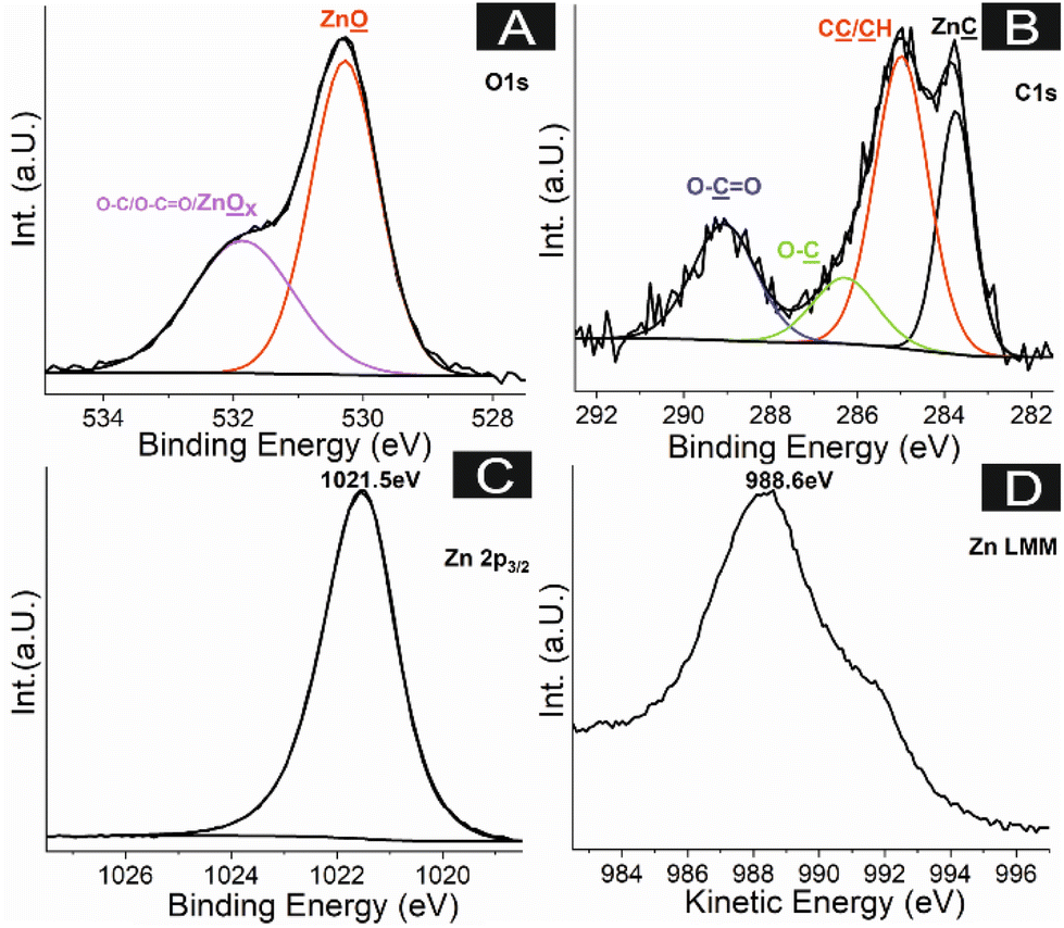 | ||
| Fig. 3 (A) C 1s, (B) O 1s, (C) Zn 2p3/2, (D) Zn LMM XPS spectra of the ZnO@VACNT composite surface. | ||
Here, Zn 2p3/2 (Fig. 3C) and Zn LMM spectra (Fig. 3D) reveal main peaks at 1021.5 eV and 988.6 eV respectively, which correspond to ZnO species signal.
To show that the VACNT host structure remains intact, despite the ZnO deposition, XPS analysis was performed on a sample where most of the composite was mechanically removed (see Fig. S3‡).
In accord to the pristine VACNT architecture the ZnO coated VACNTs show a homogeneous deposition alongside the VACNT (Fig. 4A).
 | ||
| Fig. 4 (A) SEM micrograph of pristine VACNTs. (B) Shows a SEM image of the ZnO@VACNT composite. | ||
The respective TEM images also confirm a homogeneous distribution of crystalline ZnO particles with a size of about 10–15 nm (Fig. 5).
 | ||
| Fig. 5 TEM image of the isolated ZnO@CNT structure unhinged from the ZnO@VACNT composite by ultra-sonification. | ||
Gas phase conversion of ZnO@VACNT to ZIF-8@VACNT composite
The as prepared ZnO@VACNT and the crystalline Hmim were placed on separate sides in a sealed glass vessel (see Fig. 1) to ensure that the transformation of ZnO particles to ZIF-8 is a vapour solid reaction with gas phase diffusion as transport mechanism. The sample was repeatedly investigated during the process by ex situ XRD which allowed to monitor the conversion process at different time intervals. After 24 h of reaction time new reflexes appeared which could be assigned to the formed ZIF-8. These reflexes grew further in intensity with increasing reaction time whereas the ZnO reflexes decrease and disappear completely after 72 h of reaction time (Fig. 6). After 72 h the XRD shows solely the typical ZIF-8 pattern, and no further changes occur even after 108 h of reaction time indicating a completion of the reaction. Longer reaction times cause no significant change within the measured diffraction pattern of the composite structure. | ||
| Fig. 6 Diffraction pattern of a ZnO@VACNT sample after different hours of reaction time with gaseous Hmim (24 h light blue, 72 h violet, 108 h blue). Red trace shows an unreacted sample of ZnO@VACNT while the green trace is a ZIF-8 sample shown as references. Green circles show initially first appearing ZIF-8 reflexes within the reacting ZnO@VACNT sample. | ||
The ZIF-8 particles appear as irregular shaped particles on the VACNTs (Fig. 7). The observation of an irregular shaped morphology of the resulting ZIF-8 crystals is in accordance to reports for gas phase transformations of ZnO to ZIF-8.19,38 The formed ZIF-8 shows a volume expansion compared to the starting ZnO particles due to the difference in physical density of ZnO (5.61 g cm−3) vs. ZIF-8 (0.95 g cm−3).38 This decrease in density results in a volume expansion when performing the solid-to-solid transformation which explains the irregular shape of ZIF-8 compared to regular shaped ZIF-8 particles obtained from a bottom-up solution phase synthesis.
 | ||
| Fig. 7 (A) SEM image of the outside tips of the ZIF-8@VACNT composite where the complete and dense coverage of the CNTs is visible. (B) SEM image of the inner part of the ZIF-8@VACNT composite with intact CNT alignment and homogenously deposited ZIF-8 particles. | ||
Fig. 7A shows the outer and top surface of the ZIF-8@VACNT composite where the coverage of the VACNT with ZIF-8 is dense and forms a nearly continuous film covering the entire VACNT surface while Fig. 7B represents the inner part of the ZIF-8@VACNT composite after mechanical break-up of the entire VACNT block which reveals an intact, straight, and highly parallel oriented 3D architecture in the composite.
Interestingly, the coverage of the VACNTs in the inner part of the architecture appears less dense compared to the outer surface. This may be attributed to a diminished gas penetration of the Hmim molecules in the inside of the VACNT bundle compared to its outer surface. Nonetheless, the homogenous growth of ZIF-8 particles within the VACNT array as shown in Fig. 7 confirms that the gaseous linker reaches all parts of the interior VACNT structure and therefore proves that it is able to react even with the interior of the ZnO@VACNT array.
In TEM the ZIF-8 can be detected as homogenous film which wraps around the CNTs and can be identified by a slightly higher contrast when compared to the pristine CNT material (Fig. 8Avs.8B)
 | ||
| Fig. 8 (A) Shows the ZIF-8 film with a higher contrast covering the CNTs, while (B) shows the bare, pristine CNTs. Again, the CNTs in A and B are unhinged from a ZnO@VACNT and pristine VACNT architecture by ultrasonication. | ||
This observation strongly supports a complete conversion of the deposited ZnO particles since the latter show a strong contrast in TEM and can therefore easily be distinguished from the CNTs (see Fig. 5).
IR and Raman spectra of the ZIF-8@VACNT composite show the characteristic vibration modes of the coordinated imidazole linker molecule. The IR of the composite lacks the NH functionality which is characteristic for ZIF-8, thus indicating a successful ZIF-8 formation (see Fig. S4 and S5‡).
Influence of temperature on the ZIF-8 formation
Earlier studies of gas phase transformation reactions of bare ZnO to ZIF-8 report on reaction times up to 42 hours, in a temperature range of 145 to 180 °C.38 The herein reported process runs at a lower conversion temperature of up to 80 °C. Moreover, on the extent of a longer reaction time (6 weeks) a conversion of the ZnO@VACNT composite to the ZIF-8@VACNT composite can even be realised at a temperature of 50 °C.The diffraction pattern of this low temperature approach reveals reflexes of ZIF-8, VACNTs and some residual reflexes that can be assigned to ZnO (Fig. 9).
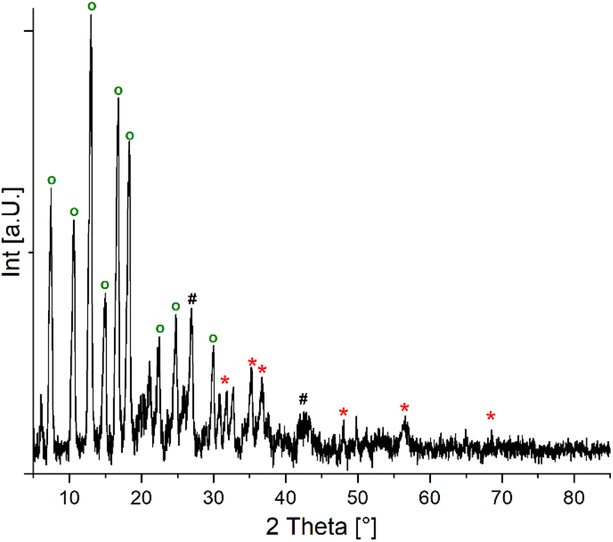 | ||
| Fig. 9 Diffraction pattern of a ZnO@VACNT composite sample converted at 50 °C over six weeks of reaction time. ZIF-8 reflexes are marked as green circles while the remaining ZnO reflexes are marked with a red star. The [200] and [101] graphite reflexes are marked with a black hash. | ||
Moreover, TEM reveals that at 50 °C CNTs are covered selectively by a ZIF-8 film (Fig. 10) as has been already seen at a conversion temperature of 80 °C (see Fig. 8B). However, unreacted ZnO particles are also visible at that low conversion temperature in accordance with the findings from the XRD characterization (Fig. 9).
 | ||
| Fig. 10 TEM image of a ZnO@VACNT composite sample converted at 50 °C over the course of six weeks. Besides the ZIF-8 film formation (green circle) the sample contains still unreacted ZnO visible as contrast rich dark spots (circled in red). Sample was prepared by ultrasonication to unhinge the CNTs from the VACNT architecture. | ||
This indicates that the deposited ZnO is partly transformed to ZIF-8 at this low conversion temperature. The existence of unreacted ZnO has been expected, when taking the previous results of the conversion reaction at 80 °C into account. Here a slower conversion in the inner parts of the CNT array was observed and was related to a lesser gas penetration of Hmim molecules into the VACNT structure. Now, due to the even lower conversion temperature of 50 °C the diffusion of gaseous Hmim seems even more hampered leading to a slower and lesser conversion rate compared to the reaction performed at 80 °C. Temperatures above 100 °C, however, lead to a faster conversion of ZnO to ZIF-8 coupled with a faster volume expansion which leads to a higher surface tension and therefore to a significant change in the sample morphology and a loss of the 3 D VACNT architecture.
Dependence of the ZIF-8@VACNT surface area on the conversion time
An important aspect of ZIF-8@VACNT composite is the obtained surface area and the respective porosity. The BET surface area of pristine VACNTs was determined to be 603.489 m2 g−1. The ZIF-8@VACNT composite obtained after 72 h of reaction time shows a comparable surface area of 631.381 m2 g−1. However, the individual contribution to the overall surface area reveals a micropore area of 526.21 m2 g−1 of the ZIF-8 part of the composite paired with and an external surface area of 105.172 m2 g−1 originating from the VACNT. This shows clearly that the ZIF-8 covers most of the VACNT surface. Longer reaction times between the ZnO@VACNT composite and the linker Hmim indeed resulted in an increase of surface area from 631.381 m2 g−1 (72 h) to 950.325, 1277.505 and finally to 1569.919 m2 g−1 for reaction times of 120 h, 192 h and 504 h, respectively. This indicates a steady evolution of the microscopic pore arrangement due to an increase in ZIF-8 formation on the surface of the VACNT architecture over time. Nevertheless, characteristic diffraction peaks for ZIF-8 are already obtained after 72 h. The observed increase in surface area which might then lead to a full evolution of the ZIF-8 framework can either be explained by a longer exposure to the gaseous linker or just by the time spent at the employed temperature necessary for the full formation of the final ZIF-8 framework. To conclude on that, we studied the change in the active surface area of a ZIF-8@VACNT sample before and after a thermal treatment at 80 °C in an open vessel for 24 h without the Hmim linker.The BET surface after such thermal treatment was determined to be 949.337 m2 g−1, which is nearly the same as the one of 950.325 m2 g−1 measured before the thermal treatment. If the distribution of external and micropore surface is compared it shows that a reduction of the micropore volume from 858.483 to 846.980 m2 g−1 could be observed. This might suggest that indeed only the presence of additional linker leads to a full conversion of the ZnO particles into the ZIF-8 framework. Solely longer reaction times might influence ZIF-8 particle morphology too and convert already formed irregular shaped ZIF-8 particles (72 h reaction time, Fig. 7) into more regular shaped larger particles due to an Ostwald ripening process. Fig. 11 shows the ZIF-8@VACNT composite after three weeks of reaction time, where VACNT strains are fully embedded into larger intergrown ZIF-8 crystal agglomerates.
 | ||
| Fig. 11 SEM images of a ZIF-8@VACNT sample (80 °C/21 d), (A) top view and (B) view alongside a completely covered VACNT bundle. | ||
Gravimetric CO2 adsorption measurements of the ZIF-8@VACNT composite
It has been reported that ZIF-8@CNT composites show enhanced adsorption capacities for CO2 in comparison to pristine ZIF-8. Such ZIF-8@CNT composites are prepared by solution-based methods containing a varying amount of multi walled CNTs as additive. The resulting composites are reported to possess surface areas in the range of 917.4 m2 g−1 (ref. 29) to 1997 m2 g−1 (ref. 27) with most of the studied samples in the area of ∼1200 m2 g−1.27–29,39 It is stated that the surface area is strongly correlated to the added CNTs where less CNT addition results in higher surface area of the composite. CO2 adsorption measurements were mainly conducted in pressure regions of 1 bar and below, where it was shown that CO2 uptake could be increased in comparison to sole ZIF-8. Within this pressure regime it was concluded that the additional CNT surface is negligible for the CO2 adsorption since CNTs are reported to show enhanced adsorption properties only in pressure regimes higher than 1 bar due to their mesoporosity and that the enhancement is based on the interaction between ZIF-8 and CNT surface.40In the pressure regime >1 bar adsorption capacities of 8 mmol g−1 CO2 at 30 bar at 308 K were reported, for a ZIF-8@CNT composite with a distribution of 96.37 w% ZIF-8 and 3.63 w% CNTs resulting in a surface area of 1997 m2 g−1.27 The ZIF-8@VACNT composite (obtained by a reaction time of 8d) is studied in the pressure range of one to 30 bar. The composite has a surface area of 1277.51 m2 g−1 and a composition of 72.48 w% ZIF-8 and 27.51 w% CNTs determined by TGA.
The composite shows adsorption capacities of 6.05 mmol g−1 for CO2 and 1.20 mmol g−1 for N2 at 30 bar and 298 K respectively. As expected, the composite shows better adsorption properties for CO2 than for N2 (Fig. 11). Due to the interaction of the ZIF-8 with the different gases. The incorporation of CNTs shifts the selectivity of the ZIF-8 further towards CO2.27,28 The CO2 uptake is higher compared to that of pristine VACNTs which are reported to possess an adsorption capacity of approx. 4 mmol g−1 of CO2 at 30 bar.40 Pristine, bare ZIF-8 shows a huge adsorption capacity up to seven bar due to its microporous structure with a steep progression but runs into a saturated CO2 uptake afterwards.27 VACNTs on the other hand show a linear progression and therefore a linear and steady uptake of CO2 at pressures >1 bar up to pressures >30 bar.41
For the ZIF-8@VACNT composite the progression of the measured CO2 uptake as shown in Fig. 12 can be separated into two parts attributed to the different components of the composite. First a steep rise caused by the ZIF-8 part of the composite which can be observed up to a pressure of seven bar. When increasing the pressure beyond that a more linear progress is observable which can be related to the contribution of the VACNTs. Especially this later additional linear progressive CO2 uptake caused by the VACNT contribution to the adsorption shows the synergy between VACNTs and ZIF-8 as a composite material and its potential to further enhance adsorption capacities in various pressure regimes depending on the individual properties of the components.
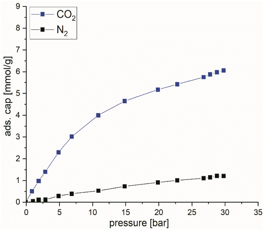 | ||
| Fig. 12 Adsorption capacity of the ZIF-8@VACNT composite towards CO2 (blue trace) and N2 (black trace) in the pressure range of 1 to 30 bar. | ||
Conclusions
A straightforward all gas phase synthesis route employing ALD to deposit nano scaled ZnO onto the VACNT surface followed by a gas phase transformation process which allows to convert the ZnO into a high surface area crystalline ZIF-8 directly on the surface of VACNTs is presented. A temperature of 80 °C was found most suitable for the transformation of the ZnO to crystalline ZIF-8 employing sublimed linker Hmim and resulting in a high surface area 3 D network of the ZIF-8@VACNT composite. Higher temperatures lead to a loss of the 3 D VACNT architecture whereas lower temperatures result in an incomplete conversion even at longer reaction times. A reaction time of 72 h proved to be sufficient for a full conversion of ZnO to ZIF-8 at 80 °C while longer reaction times result in higher surface areas up to 1569.92 m2 g−1 due to a more distinct growth which leads to well-formed ZIF-8 particles onto the VACNT surface. The ZIF-8 composite with a surface area of 1277 m2 g−1 shows a CO2 adsorption capacity of 6.05 mmol g−1 which is enhanced compared to bare VACNTs. From the comparison of the composite with pristine VACNTs and ZIF-8 alone the contribution of both parts is observable and points out to the unexplored potential of this composite material in adsorption processes. Moreover, the gas phase approach introduced herein could be expandable to other MOF materials and host structures thus broadening the synthetic scope of this gas phase method further.Conflicts of interest
There are no conflicts to declare.Acknowledgements
TEM measurements were done at the ERC Jülich, Germany under contract ERC-TUDa1. We thank Jörg Engstler (TUDa) for TEM studies.References
- H. Furukawa, K. E. Cordova, M. O'Keeffe and O. M. Yaghi, Science, 2013, 341, 1230444 CrossRef PubMed.
- A. J. Cruz, G. Arnauts, M. Obst, D. E. Kravchenko, P. M. Vereecken, S. De Feyter, I. Stassen, T. Hauffman and R. Ameloot, Dalton Trans., 2021, 50, 6784–6788 RSC.
- Y.-R. Lee, J. Kim and W.-S. Ahn, Korean J. Chem. Eng., 2013, 30, 1667–1680 CrossRef CAS.
- K. S. Park, Z. Ni, A. P. Cote, J. Y. Choi, R. Huang, F. J. Uribe-Romo, H. K. Chae, M. O'Keeffe and O. M. Yaghi, Proc. Natl. Acad. Sci. U. S. A., 2006, 103, 10186–10191 CrossRef CAS PubMed.
- J. Troyano, A. Carné-Sánchez, C. Avci, I. Imaz and D. Maspoch, Chem. Soc. Rev., 2019, 48, 5534–5546 RSC.
- D. Matatagui, A. Sainz-Vidal, I. Gràcia, E. Figueras, C. Cané and J. M. Saniger, Sens. Actuators, B, 2018, 274, 601–608 CrossRef CAS.
- X. Yang, Z. Wen, Z. Wu and X. Luo, Inorg. Chem. Front., 2018, 5, 687–693 RSC.
- Q. Wang, Y. Sun, S. Li, P. Zhang and Q. Yao, RSC Adv., 2020, 10, 37600–37620 RSC.
- S. Eslava, L. Zhang, S. Esconjauregui, J. Yang, K. Vanstreels, M. R. Baklanov and E. Saiz, Chem. Mater., 2013, 25, 27–33 CrossRef CAS.
- Y.-R. Lee, M.-S. Jang, H.-Y. Cho, H.-J. Kwon, S. Kim and W.-S. Ahn, Chem. Eng. J., 2015, 271, 276–280 CrossRef CAS.
- E. P. Valadez Sánchez, H. Gliemann, K. Haas-Santo, C. Wöll and R. Dittmeyer, Chem. Ing. Tech., 2016, 88, 1798–1805 CrossRef.
- X. Shi, Y. Shan, M. Du and H. Pang, Coord. Chem. Rev., 2021, 444, 214060 CrossRef CAS.
- Y.-H. Xiao, Z.-G. Gu and J. Zhang, Nanoscale, 2020, 12, 12712–12730 RSC.
- A. Pichon, A. Lazuen-Garay and S. L. James, CrystEngComm, 2006, 8, 211 RSC.
- E. Virmani, J. M. Rotter, A. Mähringer, T. von Zons, A. Godt, T. Bein, S. Wuttke and D. D. Medina, J. Am. Chem. Soc., 2018, 140, 4812–4819 CrossRef CAS PubMed.
- E. Ahvenniemi and M. Karppinen, Chem. Commun., 2016, 52, 1139–1142 RSC.
- P. Su, M. Tu, R. Ameloot and W. Li, Acc. Chem. Res., 2022, 55, 186–196 CrossRef CAS PubMed.
- I. Stassen, N. Campagnol, J. Fransaer, P. Vereecken, D. De Vos and R. Ameloot, CrystEngComm, 2013, 15, 9308 RSC.
- I. Stassen, M. Styles, G. Grenci, H. V. Gorp, W. Vanderlinden, S. D. Feyter, P. Falcaro, D. D. Vos, P. Vereecken and R. Ameloot, Nat. Mater., 2016, 15, 304–310 CrossRef CAS PubMed.
- J. Holopainen, M. J. Heikkilä, L. D. Salmi, K. Ainassaari and M. Ritala, Microporous Mesoporous Mater., 2018, 267, 212–220 CrossRef CAS.
- N. Paknameh, S. Fatemi and M. Razavian, Mater. Chem. Phys., 2019, 235, 121764 CrossRef CAS.
- C.-W. Chang, Yu.-H. Kao, P.-H. Shen, Po.-C. Kang and C.-Yu Wang, J. Hazard. Mater., 2020, 400, 122974 CrossRef PubMed.
- A. Jagan Mohan Reddy, N. K. Katari, P. Nagaraju, K. Hussain Reddy and M. S. Surendra Babu, J. Mater. Sci.: Mater. Electron., 2021, 32, 7827–7840 CrossRef CAS.
- S. Wang, J. Cui, S. Zhang, X. Xie and W. Xia, Mater. Res. Express, 2020, 7, 025304 CrossRef CAS.
- P. Neelakanda, E. Barankova and K.-V. Peinemann, Microporous Mesoporous Mater., 2016, 220, 215–219 CrossRef CAS.
- L. Cheng, P. Yan, X. Yang, H. Zou, H. Yang and H. Liang, J. Alloys Compd., 2020, 825, 154132 CrossRef CAS.
- Y. Yang, L. Ge, V. Rudolph and Z. Zhu, Dalton Trans., 2014, 43, 7028 RSC.
- M. Konni, S. Doddi, A. S. Dadhich and S. B. Mukkamala, Surf. Interfaces, 2018, 12, 20–25 CrossRef CAS.
- J. Dai, X. Xiao, S. Duan, J. Liu, J. He, J. Lei and L. Wang, Chem. Eng. J., 2018, 331, 64–74 CrossRef CAS.
- J. Yoo, S. Lee, C. K. Lee, C. Kim, T. Fujigaya, H. J. Park, N. Nakashima and J. K. Shim, RSC Adv., 2014, 4, 49614–49619 RSC.
- Y. Zhang, Y. Tong, X. Li, S. Guo, H. Zhang, X. Chen, K. Cai, L. Cheng and W. He, ACS Omega, 2021, 6, 18566–18575 CrossRef CAS PubMed.
- R. Joshi, J. Engstler, L. Houben, M. Bar Sadan, A. Weidenkaff, P. Mandaliev, A. Issanin and J. J. Schneider, ChemCatChem, 2010, 2, 1069–1073 CrossRef CAS.
- S. Okeil, J. Krausmann, I. Dönges, S. Pfleger, J. Engstler and J. J. Schneider, Dalton Trans., 2017, 46, 5189–5201 RSC.
- Y.-S. Min, I. H. Lee, Y. H. Lee and C. S. Hwang, CrystEngComm, 2011, 13, 3451 RSC.
- Q. Dai, S. Peng, Z. Zhang, Y. Liu, M. Fan and F. Zhao, Front. Bioeng. Biotechnol., 2021, 9, 635338 CrossRef PubMed.
- M. Chen, X. Wang, Y. H. Yu, Z. L. Pei, X. D. Bai, C. Sun, R. F. Huang and L. S. Wen, Appl. Surf. Sci., 2000, 158, 134–140 CrossRef CAS.
- L. S. Dake, D. R. Baer and J. M. Zachara, Surf. Interface Anal., 1989, 14, 71–75 CrossRef CAS.
- S. Tanaka, K. Sakamoto, H. Inada, M. Kawata, G. Takasaki and K. Imawaka, Langmuir, 2018, 34, 7028–7033 CrossRef CAS PubMed.
- L. Dumée, L. He, M. Hill, B. Zhu, M. Duke, J. Schütz, F. She, H. Wang, S. Gray, P. Hodgson and L. Kong, J. Mater. Chem. A, 2013, 1, 9208 RSC.
- D. J. Babu, M. Lange, G. Cherkashinin, A. Issanin, R. Staudt and J. J. Schneider, Carbon, 2013, 61, 616–623 CrossRef CAS.
- D. J. Babu, M. Bruns and J. J. Schneider, Carbon, 2017, 125, 327–335 CrossRef CAS.
Footnotes |
| † In memoriam of Prof. Dr Günter Schmid. |
| ‡ Electronic supplementary information (ESI) available. See DOI: https://doi.org/10.1039/d2dt02155b |
| This journal is © The Royal Society of Chemistry 2022 |