 Open Access Article
Creative Commons Attribution 3.0 Unported Licence
A low-temperature thermal ALD process for nickel utilizing dichlorobis(triethylphosphine)nickel(II) and 1,4-bis(trimethylgermyl)-1,4-dihydropyrazine†
Anton
Vihervaara
 a,
Timo
Hatanpää
 a,
Kenichiro
Mizohata
 b,
Mykhailo
Chundak
 a,
Georgi
Popov
 a and
Mikko
Ritala
 *a
*a
aDepartment of Chemistry, University of Helsinki, P. O. Box 55, FI-00014 Helsinki, Finland. E-mail: mikko.ritala@helsinki.fi
bDepartment of Physics, University of Helsinki, P. O. Box 43, FI-00014 Helsinki, Finland
First published on 25th June 2022
Abstract
In this work, we developed a new ALD process for nickel metal from dichlorobis(triethylphosphine)nickel(II) (NiCl2(PEt3)2) and 1,4-bis(trimethylgermyl)-1,4-dihydropyrazine ((Me3Ge)2DHP). A series of phosphine adducts of nickel and cobalt halides were synthesized and characterized for their volatility and thermal stability. Also (Me3Ge)2DHP is a novel reducing agent in ALD. Smooth nickel films were deposited on different substrate materials at 110 °C, which is the lowest deposition temperature for Ni metal found in the literature. The growth rate is 0.2 Å per cycle when the film is not continuous and decreases to 0.1 Å per cycle after the film becomes pinhole-free. Besides a small amount (7 at%) of carbidic carbon, the films have only small amounts of impurities. Most notably, the chlorine content is below 0.2 at%, indicating efficient reduction. Furthermore, we think that (Me3Ge)2DHP can open new avenues for the ALD of other metals at low temperatures.
Introduction
Nickel thin films may be used in different applications ranging from microelectronics to protective coatings1 and catalysis.2,3 Ni is one of the candidates for replacing copper in future interconnects in integrated circuits (IC) as it has low resistivity and a low electron mean free path, which causes the resistivity to become lower than that of copper when the interconnect dimensions are made small enough.4 For example, cobalt was calculated to surpass copper in conductivity when the line width goes below 10 nm and nickel has similar bulk resistivity with even a lower electron mean free path than cobalt.5 The Ni films deposited on silicon can be converted to NiSi, a low-resistivity contact material, by heating the films. Fully silicided Ni gates can be used in complementary metal oxide semiconductors.6 Due to its ferromagnetic properties, nickel is essential for the development of magnetic memory. Spin-transfer torque magnetoresisitive random-access memory (STT-MRAM) has been considered as universal memory that may revolutionize the whole microelectronics industry someday.7For the majority of future applications, it is essential to have high-quality thin films deposited uniformly over large areas and on complex 3D structures. The best method to meet these requirements is atomic layer deposition (ALD). ALD relies on saturated alternate surface reactions that provide conformal and uniform film growth across the substrate. Usually the surface reactions are activated thermally, but also plasma activation is used increasingly. About half of the reported nickel ALD processes are thermal processes and the other half are plasma processes. While plasma processes have advantages like low deposition temperature, thermal ALD is generally preferred as plasma may damage the underlying substrate material or compromise the conformality of the film. Thermal ALD is also easier to use in industry as the reactor design is simpler and batch processing is possible. However, the development of thermal ALD processes for Ni has been hindered by the lack of suitable precursors and precursor combinations. The lack of efficient reducing agents is especially apparent and many of the found reducing agents work only with specific metal precursors. A low deposition temperature is also desirable, as it generally results in smoother films, less agglomeration and thus continuous films at lower thickness.
Metallic nickel has been successfully deposited via ALD from a selection of nickel precursors and reducing agents. Molecular hydrogen has been used to deposit nickel films with bis(acetylacetonato)nickel(II) (Ni(acac)2) at 250 °C but this process worked only on metal substrates and no properties of the films were provided.8 Bis(N,N′-diisopropylacetamidinato)nickel(II) (Ni(iPrAMD)2) was also used with H2 at 250 °C and this process worked on both metal and non-metal substrates. The process had a growth rate of only 0.04 Å per cycle however.9 Likewise, the bis(dimethylamino-2-methyl-2-butoxo)nickel(II) (Ni(dmamb)2) + H2 process worked at 200–250 °C on a silicon surface, but these Ni films had up to 25 at% of carbon, indicating possible precursor decomposition.10 Also, ammonia was used with Ni(dmamb)2 and high-quality Ni films were obtained (resistivity of 25 μΩ cm), but the required deposition temperature was quite high, 300 °C.11 Using hydrazine with Ni(acac)2(tmeda) (tmeda = N,N,N′,N′-tetramethylethylenediamine) at 240–280 °C resulted in high-quality Ni films (95 at% Ni and resistivity of 18 μΩ cm) with a high growth rate of 2.1 Å per cycle.12 Ni(acac)2(py)2 (py = pyridine) also reacted with hydrazine but this combination had a lower growth rate of 0.8 Å per cycle. In one study, hydrazine was combined with Ni(dmap)2 and formic acid in a three-step process which did result in a deposition of metallic nickel.13 Another three-step process for the ALD of Ni utilized bis(1,4-di-tert-butyl-1,3-diazadienyl)nickel(II) (Ni(tBu2DAD)2), formic acid and 1,4-bis(trimethylsilyl)-1,4-dihydropyrazine ((Me3Si)2DHP) at 180 °C.14 The films deposited with this process were 94 at% nickel.
tert-Butylamine (tBuNH2) combined with Ni(tBu2DAD)2 at 160–220 °C resulted in high-quality Ni films (>97 at% Ni and a resistivity of 22 μΩ cm), but this process worked only on metal surfaces. The growth rate was 0.6 Å per cycle.15 Similarly, boranedimethylamine (BH3NHMe2) combined with bis(1-(tert-butylimino)-2,3-dimethylbutan-2-olate)nickel(II) (Ni(tbidmb)2) at 180 °C resulted in film growth only on the Ru substrates.16 Finally, high-purity (95 at% Ni and a resistivity of 27 μΩ cm) Ni films were obtained using Ni(acac)2 and methanol at 250–300 °C, although the growth rate was fairly low (0.07 Å per cycle).17
Out of the reported thermal Ni ALD processes, some are applicable only on metallic substrates, which is beneficial for area-selective deposition but otherwise a limitation, and some others require relatively high deposition temperatures. The only low-temperature processes (<200 °C) are those utilizing Ni(tbidmb)2 and BH3(NHMe2) (180 °C),16 and Ni(tBudad)2 and tBuNH2 (160–220 °C).15 However, these processes too deposit films only on metallic substrates. It also seems that many reducing agents work only with certain metal precursors and therefore do not act as general reducing agents.
Other reducing agents that can be used in ALD include metal hydrides. Tributyltin hydride and tributylgermanium hydride have been used with NiCl2(tmpda) (tmpda = N,N,N′,N′-tetramethyl-1,3-propanediamine) to deposit intermetallic Ni3Sn2 and Ni2Ge films at 160 °C and 180 °C, respectively.18,19 While the processes did not result in Ni metal, the studies clearly indicated that these hydrides do have reducing capabilities. In addition, they attract interest in the applicability of nickel halide precursors in ALD. The advantages of the halide precursors are their simplicity, availability, low price and good reactivity with many co-precursors. Their disadvantages might be limited volatility, the corrosiveness of the byproducts, and possible halide contamination in the deposited films.
1,4-Bis(trimethylsilyl)-1,4-dihydropyrazine ((Me3Si)2DHP) and 1,4-bis(trimethyl)-2-methyl-2,5-cyclohexadiene ((Me3Si)2CHD) are intriguing reducing agents which have been used together with TiCl4 and SnCl4 to deposit titanium and tin films, respectively.20,21 Titanium especially has a low standard redox potential of E° = −1.63 V, indicating that (Me3Si)2DHP is a powerful reducing agent. While the previous studies20–22 have shown that (Me3Si)2DHP and (Me3Si)2CHD are good reducing agents, they have been demonstrated to work with only metal chlorides, which is understandable because in the reactions of these compounds with metal chlorides a highly favorable byproduct of trimethylchlorosilane is formed. However, as shown in this study, (Me3Si)2DHP does not afford good nickel films from the adducts of nickel halides.
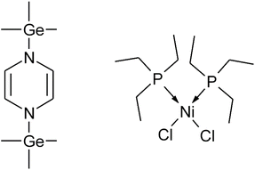
In this work 1,4-bis(trimethylgermyl)-1.4-dihydropyrazine ((Me3Ge)2DHP) (Fig. 1) is introduced as a considerably more reactive reducing agent than (Me3Si)2DHP. (Me3Ge)2DHP is used together with dichlorobis(triethylphosphine)nickel(II) (NiCl2(PEt3)2) (Fig. 1) for the ALD of nickel metal films at a low temperature of 110 °C. Both precursors are new to ALD. NiCl2(PEt3)2 is one compound in a series of phosphine adducts of nickel halides studied along with the cobalt counterparts. The findings of these phosphine adducts are also presented in this work. The phosphine adducts are a continuation of the series of amine adducts of nickel and cobalt halides18,19,23,24 that we have been studying as possible ALD precursors. Among the phosphine adducts, NiCl2(PEt3)2 was identified as one viable candidate with sufficient thermal stability and good volatility, achieving low-temperature ALD.
Experimental section
Precursor synthesis and characterization
Synthesis and all manipulation of the compounds were performed under rigorous exclusion of air and moisture using Schlenk techniques and an argon-filled glove box. Me3GeCl (Gelest), Li granules (Aldrich), pyrazine (Aldrich, >99%), anhydrous NiCl2 (for synthesis, Aldrich), anhydrous CoCl2 (99+%, Strem) and PEt3 10 wt% in hexane (ABCR, 99%) were used as received. Tetrahydrofuran (THF) was distilled freshly from the sodium benzophenone ketyl radical and sodium metal. Thermogravimetric analysis (TGA) was performed using Mettler Toledo TGA/DSC 3+ equipment. Measurements were performed under a flowing 1 atm N2 atmosphere and the 10–11 mg samples were heated from 25 to 600 °C at a rate of 10 °C min−1. Melting points were determined from the SDTA data measured using TGA/DSC 3+ equipment. NMR spectra were measured using a Bruker Avance 400 MHz spectrometer. 1H and 13C shifts are referenced to internal solvent resonances and reported in parts per million relative to TMS.![[double bond, length as m-dash]](https://www.rsc.org/images/entities/char_e001.gif) CH–N) ppm. 13C NMR (benzene-d6, 100.61 MHz, 25 °C): δ = −1.57 (s, Ge(CH3)), 119.20 (s,
CH–N) ppm. 13C NMR (benzene-d6, 100.61 MHz, 25 °C): δ = −1.57 (s, Ge(CH3)), 119.20 (s, ![[double bond, length as m-dash]](https://www.rsc.org/images/entities/char_e001.gif) CH–N) ppm.
CH–N) ppm.
A similar synthesis procedure was used for all other phosphine adducts of nickel halides.
A similar synthesis procedure was used for all other phosphine adducts of cobalt halides.
Film deposition
Deposition experiments were performed in an F-120 hot-wall flow-type ALD reactor (ASM Microchemistry). The reactor had a pressure of approximately 10 mbar and N2 (AGA 5.0) was used as the carrier and purging gas. Both NiCl2(PEt3)2 and (Me3Ge)2DHP were evaporated from open glass boats held inside the reactor at 100 and 35 °C for NiCl2(PEt3)2 and (Me3Ge)2DHP, respectively. Pulsing was done by inert gas valving and the pulse times were varied from 0.5 to 3.0 s. A purge time of 1.0 s was used for most of the depositions. The substrates were 5 × 5 cm2 native oxide-terminated Si and soda lime glass. In addition, film depositions were tested on Cu, TiN and Al2O3 films.Film characterization
The crystal structure of the films was studied with X-ray diffraction with a PANalytical X'Pert Pro MPD X-ray diffractometer. A grazing incidence geometry was used with Cu Kα (λ = 1.54 Å) radiation having an incidence angle of 1°. The results were analysed with the PANalytical Highscore Plus 4.1 software. Diffractograms were analysed with the MAUD 2.992 software to determine the size of the crystallites.25Film thicknesses were measured with energy-dispersive X-ray spectrometry (EDS) using an Oxford INCA 350 connected to a Hitachi scanning electron microscope (SEM). An electron voltage of 20 kV was used and the thickness was calculated from Ni Kα X-ray lines with the GMRFILM program using a bulk density of 8.9 g cm−3 for nickel.26 An uncertainty of 5% was estimated for the thickness measurements due to a slight fluctuation of the electron beam current and possible deviations from the bulk density. The film composition was measured by time-of-flight elastic recoil detection analysis (ToF-ERDA) using a 40 MeV 127I7+ ion beam.
A field emission scanning electron microscope (FESEM) was used to evaluate the morphology and nucleation of the films. Sheet resistances were measured from the films deposited on soda lime glass substrates using a four-point probe (CPS Probe Station, Cascade Microtech combined with a Keithley 2400 SourceMeter). Sheet resistance was measured as an average from nine measurement points uniformly distributed across the film/substrate. The resistivity was obtained by multiplying the sheet resistance by the film thickness.
Atomic force microscopy (AFM, Veeco Multimode V instrument) was used to study the surface morphology and roughness of the films. A Si probe with a nominal tip radius of 10 nm and a spring constant of 3 N m−1 was used to capture images in air from the films deposited on the Si substrates. Roughness was calculated as a root-mean-square value (Rq) from the flattened images. Flattening was performed to remove artefacts from the sample tilt and scanner bow.
Further characterization was performed with XPS and Raman spectroscopy. The XPS measurements were performed with a Prevac system EA-15 hemispherical electrostatic energy analyser and RMC50 monochromatic X-ray source with an Al Kα anode (1486.7 eV) operated at 220 W. The base pressure during all measurements was 10−10 mbar. The pass energy for the measurements was 50 eV and that of the slit was C 0.3 × 25. Prior to the measurements the films were rastered for 1 hour with 1 keV He+ ions over an area of 5 mm × 2 mm to remove oxygen and other impurities from the surface of the films. The peak fitting was achieved with CasaXPS by GL line shape. Raman spectroscopy studies were conducted with a confocal Raman microscope (NT-MDT Ntegra) with a 532 nm laser and a 100× objective. Micro-Raman spectra were measured in the backscattering geometry. The nominal output power of the laser was 20 mW. During each measurement 20 exposures with 4.0 s exposure time were used. Nickel foil (0.5 mm thick, annealed, 99.5%, Alfa Aesar) was used for a reference measurement.
Results and discussion
Metal precursors
Earlier we introduced diamine adducts of nickel and cobalt halides as cost-effective precursors to ALD.18,19,23,24 Nickel and cobalt halides as such are solids with polymeric structures and poor volatility. Sublimation temperatures above 350 °C are typically needed. Adding appropriate amines into the halides gives thermally stable monomeric adducts with dramatically enhanced volatility. NiCl2(tmpda) sublimes cleanly at 160–180 °C/0.5 mbar and withstands temperatures up to 250 °C.24 As compared with other known Ni and Co precursors, this volatility is among the average values. However, especially when elemental metal films are to be deposited, the volatility should be as high as possible to reach the lowest possible deposition temperature to minimize the agglomeration for achieving smoother films, and thereby continuous films at lower thickness.We have now studied the phosphine adducts of the nickel and cobalt halides. Initially a bidentate diphosphine ligand bis(diethylphosphino)ethane was studied as the adduct ligand. It was found that these compounds are thermally quite stable (>320 °C) but their volatilities are low (vacuum sublimation required temperatures over 240 °C). Surprisingly, the adducts with two monodentate alkylphosphines, PMe3 and PEt3, behave quite differently. The monodentate alkylphosphine adducts of nickel halides have very high volatility so that the compounds can be sublimed well at 70–130 °C/0.3 mbar. Unfortunately, the thermal stability of the adducts is also low so that, e.g. the upper limit for the ALD with NiCl2(PEt3)2 is as low as 130 °C. In the case of cobalt, the thermal stability is similar or higher but the volatility is also lower so that temperatures above 120 °C are needed for vacuum sublimation. Because of the small window between the evaporation temperature and the onset temperature for thermal decomposition, the ALD of cobalt was found to be impossible even though some of the adducts, especially those of CoBr2 and CoI2, can be sublimed with over 90% yields.
It seems to be a general trend that among the adducts of the different halides of cobalt and nickel the thermal stability increases in the order chloride < bromide < iodide. The trend seems to be more pronounced with cobalt. This observation is likely due to the decreasing electron affinity in the halide series that makes the metal a better π back donor, which in turn causes the phosphine ligands to bond more strongly to the metal. The bonding strengths of the phosphines may also be explained by the Lewis hard–soft acid–base (HSAB) symbiotic effect; when softer anionic ligands (here Br and I) are bonded to the metal ion, they soften the metal acidity and thereby make bonding with soft bases like phosphines more favorable.
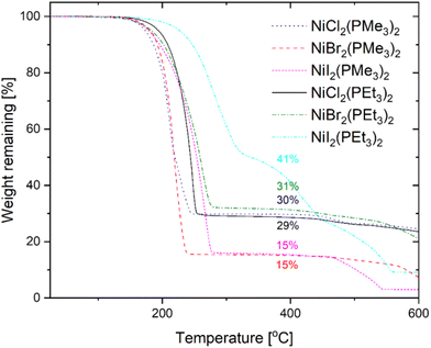
Despite the substantially increasing molecular weight from the chlorides to the iodides, the volatilities of the compounds remain quite similar – only a slight decrease is observed upon going from the chlorides to the iodides. When comparing the two phosphine ligands, PMe3 and PEt3, the adducts with the PMe3 ligand have better volatility but also lower thermal stability. However, overall, the differences seem to be quite small.
The TG curves measured under a 1 atm flowing nitrogen atmosphere for the abovementioned NiX2(PR3)2 (R = Me, Et) adducts are shown in Fig. 2. The measurements show large residues and it is likely that the weight losses are mostly due to thermal decomposition. However, the residual masses at 400 °C, i.e. after the first step of the weight loss (15–31%), are much lower than the nickel halide contents of the compounds (35–67%) and therefore it is not only the phosphine ligands that are evaporated. Part of the complex may evaporate intact or decomposition other than simple loss of the phosphine ligands might take place. The PMe3 adducts show weight loss at a lower temperature and, despite the larger metal content, they leave smaller residues than the PEt3 adducts, with NiCl2(PMe3)2 being an exception with a residue similar to NiCl2(PEt3)2. NiBr2(PMe3)2 and NiI2(PMe3)2 both show residues of 15% while the NiBr2 and NiI2 contents are 59 and 67%, respectively. This might be interpreted to indicate better volatility. However, because both decomposition and evaporation are taking place in the TGA performed at 1 atm and with uncertainty regarding what really happens to the compounds during heating, the sublimation temperatures and yields from vacuum sublimation experiments give generally a better view of the volatility of the compounds. If the weight losses are considered to be mostly due to the decomposition, the PEt3 adducts seem to be thermally more stable than the PMe3 adducts, and among the halides the adducts of nickel iodides are more stable than those of nickel chlorides and bromides. In the vacuum sublimation experiments it was seen that the PMe3 adducts do start to sublime at lower temperatures than the PEt3 adducts (70 vs. 80 °C) and also sublime faster. The sublimation yields were 92–98%.
The TG curves measured for the CoX2(PR3)2 (R = Me, Et) compounds (Fig. S1†) mainly show decomposition. For the phosphine adducts of CoCl2 the residual masses after the first mass loss step (46 and 35% for the PMe3 and PEt3 adducts, respectively) are exactly the theoretical amounts of CoCl2 (46 and 35%) in the compounds, indicating the loss of the phosphine ligands. For the bromides and iodides, the decomposition seems to be a more complicated process. However, at least in the case of the PEt3 adducts the onset of the weight loss is seen at a much higher temperature with the bromides and iodides than with the chlorides, indicating better thermal stability rather than lower volatility.
In the light of these thermal property studies, it is difficult to conclude which of the nickel precursors will show the best performance in actual ALD usage. Out of the phosphine adducts of nickel halides the PMe3 adducts have the best volatility and among these NiI2(PMe3)2 might be the most thermally stable one. The PEt3 adducts are slightly less volatile than the PMe3 adducts but the thermal stability seems to be higher. In this work, ALD studies were conducted using NiCl2(PEt3)2, which has average properties among the adducts synthesized. The selection was further affected by the above reasoning that because of the favorable byproduct the metal chloride might be more reactive with (Me3Si)2DHP than the bromide and iodide. The chloride ion is also smaller in size and together these properties might lead to higher growth rates.
Reducing agent
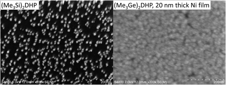
Klesko et al.20 and Stevens et al.21 showed that (Me3Si)2DHP and (Me3Si)2CHD are good reducing agents for metal halides. (Me3Si)2DHP is hypothesized to react with metal halides, forming trimethylsilylhalide and a pyrazinediyl metal compound, which immediately rearranges so that the metal cation is reduced and the anti-aromatic dihydropyrazine dianion is oxidized to aromatic pyrazine.27 However, our ALD experiments indicated that (Me3Si)2DHP does not afford good nickel films from NiCl2(PEt3)2. The growth rate was low and only nanoparticles were deposited after 1000 cycles at 110 °C (Fig. 3). Because of the unsatisfactory result, a more reactive reducing agent was still desired. Thus, a trimethylgermyl analogue of (Me3Si)2DHP, (Me3Ge)2DHP, was synthesized. (Me3Ge)2DHP is expected to react similarly to (Me3Si)2DHP.Using exactly the same synthesis procedure as that used for the trimethylsilyl analogue, the synthesis yields were low (0–20%). By optimizing the synthesis the yield was increased to 87%. (Me3Ge)2DHP is an extremely air- and moisture-sensitive orange solid that melts at 52–79 °C and can be sublimed cleanly at 80–100 °C/0.3 mbar. According to the ALD experiments, the compound seems to be stable up to only 200 °C, which is lower than the value for the trimethylsilyl analogue that can be used at least up to 240 °C (ref. 20) but probably also at much higher temperatures. This is likely due to the clearly weaker N–Ge bond compared with the N–Si bond. The bonding energies have been estimated to be around 324 and 256 kJ mol−1, for N–Si and N–Ge, respectively.28 However, apparently for the same reason for the weaker N–Ge bond, (Me3Ge)2DHP also seems to be more reactive than (Me3Si)2DHP. Considering simply the bond energies, the reaction where the Ge–N bond (256 kJ mol−1) is broken and Ge–Cl (373 kJ mol−1) is formed is more favourable than the reaction where Si–N (324 kJ mol−1) is broken and Si–Cl (416 kJ mol−1) is formed, i.e. the reaction enthalpy is more negative for (Me3Ge)2DHP. Thus it seems that what is lost in the thermal stability is gained in the reactivity. Fortunately, in this case, the thermal stability is sufficient for low-temperature processes that are also otherwise desired. In general, it appears that the weak N–Ge bond makes (Me3Ge)2DHP a potentially more generic reducing agent than (Me3Si)2DHP.
Nickel film deposition and growth characteristics
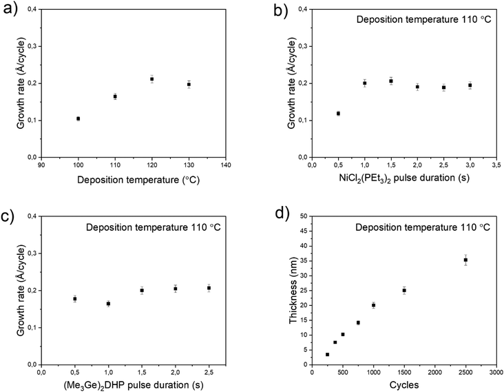
To evaluate (Me3Ge)2DHP as a more reactive reducing agent, it was tested with NiCl2(PEt3)2. A fully continuous, smooth and uniform Ni film was deposited at 110 °C, indicating a much higher reactivity and growth rate (Fig. 3). While (Me3Ge)2DHP and (Me3Si)2DHP are structurally similar molecules, it is clear that their reactivities are very different. Thus, this study focuses on Ni ALD from NiCl2(PEt3)2 and (Me3Ge)2DHP.The growth characteristics of the NiCl2(PEt3)2–(Me3Ge)2DHP process are presented in Fig. 4. The growth rate was investigated as a function of temperature ranging from 100 to 130 °C. The lower limit was dictated by using the sublimation temperature of the nickel precursor (Tsub = 100 °C). At 130 °C, the nickel precursor seemed to decompose extensively, as indicated by the formation of NiCl2 at the hot end of the precursor tube. While similar decomposition in the source tube occurred to some degree also at 120 and 110 °C, no effect on the film growth was observed and saturation of the growth rate could be achieved at 110 °C. The growth rate was found to be temperature dependent, first increasing with temperature and then remaining at the level of 0.2 Å per cycle (Fig. 4a). The resistivity of the films likewise increased with temperature from 30 to 50 μΩ cm, most likely due to the increased impurity content caused by the slight decomposition of NiCl2(PEt3)2. 110 °C was chosen as the optimal deposition temperature as the best alternative for the resistivity and growth rate.
Saturation tests were performed with both precursors at 110 °C (Fig. 4b and c). These depositions were performed with 1000 cycles and 1.0 s purges. Saturation of the growth rate to 0.2 Å per cycle was observed with both precursors. With NiCl2(PEt3)2 the saturation was reached with a 1.0 s pulse time and with (Me3Ge)2DHP it was achieved with a 1.5 s pulse time.
In a typical ALD process, the film thickness increases linearly with cycle number. However, here two regimes in the growth rate could be observed (Fig. 4d). Up to 20 nm, the growth rate was a constant 0.2 Å per cycle, but then it decreased to 0.1 Å per cycle. As the growth rate change occurs at about the same time when the film becomes fully continuous (1000 cycles, 20 nm, see below), the decrease in the growth rate can be attributed to a decreasing surface area. A smaller surface area means less adsorption sites for the metal precursor and thus less film is deposited in each cycle. This is a quite common observation in the ALD of metals.29 The sufficiency of the 1.0 s purge time was confirmed by doubling it to 2.0 s without any effect on the growth rate. The films had good uniformity across the substrate (Fig. S2†). The films were deposited successfully also on the TiN, Al2O3 and Cu films without any significant change in the growth rate. The equal growth on the insulators and metals indicates that the process is not sensitive to the underlying material.
Film characterization
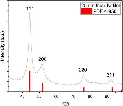
XRD measurements were conducted with the films deposited on silicon at different temperatures, and with the films deposited under optimal conditions (at 110 °C with saturative pulses) with different thicknesses (20 nm and 35 nm). All the films exhibited similar X-ray diffractograms with reflections matching those of fcc nickel (Fig. 5, ICDD PDF file 4-850). The large width of the reflections indicates small crystallites. Fitting of the diffractograms indicated that the crystallite sizes were below 10 nm, but the background shape under the peaks indicates that even smaller crystallites are present in the film.The morphology and nucleation of the films were studied with SEM and AFM. The films were smooth and became pinhole free when the thickness exceeded 20 nm (Fig. 6). The grain size was small with a lateral size of approximately 20–30 nm and this is also demonstrated by wide reflections in XRD (Fig. 5). The root mean square roughness (Rq) of the films was approximately 1.2 nm at 10 nm thickness and slightly decreased to 1.0 nm after the film thickness exceeded 20 nm and the films became fully continuous (Fig. 7). The Rq values are the average from three different measurements. For metals, the films are very smooth, which is typical also of other published ALD Ni films with roughness values varying between 0.5 and 1.5 nm.12,15,17
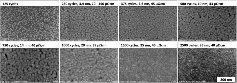 | ||
| Fig. 6 SEM images of Ni films deposited at 110 °C with varying number of cycles with their respective thicknesses and resistivities. | ||
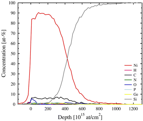
Elemental composition of the films was studied with ToF-ERDA measurements (Fig. 8 and Table 1). The films were mostly metallic nickel with about 7 at% of carbon. The other impurities are at levels below 1.5 at%. The very low chlorine content is notable and indicates efficient reduction by (Me3Ge)2DHP. Oxygen is found only from the surface of the film, which refers to post-deposition oxidation in air. Because the hydrogen content is also below 1 at%, a major part of the carbon detected must be in other forms than hydrocarbon residues.
| Element | At% |
|---|---|
| Ni | 86.8 ± 0.5 |
| C | 7.03 ± 0.16 |
| O | 1.46 ± 0.07 |
| P | 1.39 ± 0.07 |
| Ge | 1.03 ± 0.05 |
| H | 0.93 ± 0.08 |
| N | 1.14 ± 0.06 |
| Cl | <0.2 |
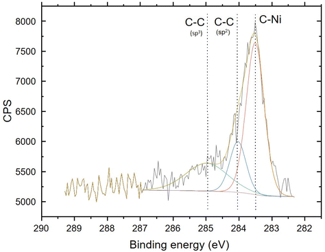
The chemical character of the 7 at% carbon detected in the films was studied using XPS. The chemical state of the carbon was revealed to be mostly carbidic (Fig. 9). The spectrum is almost identical to the one presented by Furlan et al.30 for a nickel film with 5 at% carbon. Besides the carbon and oxygen from the surface, no impurities could be reliably detected with XPS.
The chemical character of the carbon was studied further using Raman spectroscopy. Similar to all metals with the monoatomic lattice (fcc and bcc metals), metallic nickel does not show Raman bands. In contrast, carbon impurities show active Raman bands that should be seen if they are present. These include graphite, graphene, amorphous carbon and highly disordered carbon.31–33 Since none of the bands were detected (Fig. 10), the carbon in the films must be carbidic in nature and concealed within the fcc crystal structure, invisible in the Raman spectra. As a further proof of all the other forms of carbon besides Ni3C being easily detectable with Raman, Raman measurements from Co films that had similar amounts of carbon did show peaks of amorphous carbon (not shown). This indicates that this amount of carbon could clearly be seen with Raman if not carbidic.
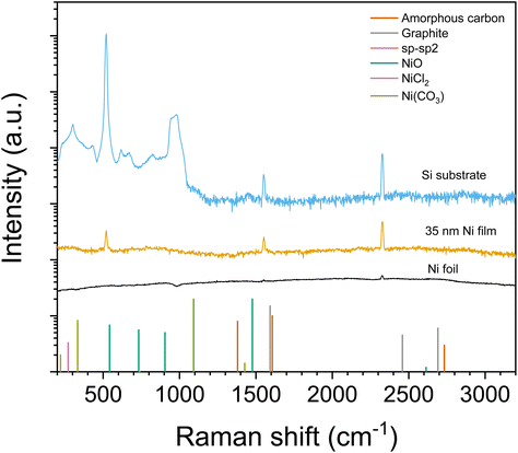 | ||
| Fig. 10 Raman spectra from a 35 nm Ni film deposited at 110 °C and, for reference, from a nickel metal foil and the Si substrate. Band positions for selected phases are shown with bars. Carbon and NiCl2 band positions are from Wu et al.32 and Lockwood et al.34 respectively. NiO and Ni(CO3) band positions are determined from ROD 3500021 and RRUFF R040157 entries respectively. | ||
The resistivities of the films were measured from soda lime glass substrates with the four-point probe. The films exhibited a resistivity of approximately 40 μΩ cm once they had become fully continuous. Nickel has a bulk resistivity of 7 μΩ cm.35 It is common for thin films to have higher resistivity than bulk materials, and the incorporated carbon is also known to increase the resistivity. Furlan et al.30 studied the resistivity of the magnetron-sputtered Ni1−xCx films. A carbon content of 3 at% resulted in a resistivity of 30 μΩ cm. Increasing the carbon content to 5 at% increased the resistivity to 62 μΩ cm. The resistivity increased linearly up to 16.3 at% of carbon, which was exceeded and the films turned from polycrystalline to amorphous, which caused a major increase in the resistivity. The resistivity values reported for the ALD-deposited Ni films range between 19 and 27 μΩ cm while the carbon content is less than 5 at%.12,15,17 Our results are in line with these, as increasing carbon content increases the resistivity and our films contain slightly more carbon than the other ALD Ni films. Furthermore, our Ni films have small grain sizes, which is also a factor increasing their resistivity.
Conclusions
A new low-temperature reducing agent, (Me3Ge)2DHP, was synthesized and found to be more efficient than the known (Me3Si)2DHP. Similar to (Me3Si)2DHP, (Me3Ge)2DHP is expected to be an efficient reducing agent for metal halides. A number of phosphine adducts of nickel and cobalt halides were studied as possible precursors for ALD. It was found that nickel halides with simple monodentate phosphines PEt3 and PMe3 have exceptionally good volatility among the adducts of nickel halides. Their thermal stability is sufficient and allows ALD usage.NiCl2(PEt3)2 was combined with (Me3Ge)2DHP to deposit metallic nickel films at a low temperature of 110 °C. This is the lowest reported deposition temperature for Ni ALD to date. The films exhibited similar resistivity to nickel films deposited earlier with ALD and while they had a small amount of carbon, it was in carbidic form and thus less detrimental to the properties of the films than amorphous carbon or graphite would be expected to be. The combination of high quality films and a low deposition temperature show potential for multiple applications. Furthermore, both precursors are novel precursors and especially (Me3Ge)2DHP can be combined with other metal halide precursors for opening up new avenues for the ALD of metals at low temperatures.
Conflicts of interest
There are no conflicts to declare.Acknowledgements
Mikko Heikkilä is acknowledged for the valuable help with the XRD analysis. ASM Microchemistry Oy is gratefully acknowledged for funding this research. The ALD Center Finland is acknowledged for the infrastructure.References
- G. Wang, Z. Gao, S. Tang, C. Chen, F. Duan, S. Zhao, S. Lin, Y. Feng, L. Zhou and Y. Qin, ACS Nano, 2012, 6, 11009–11017 CrossRef CAS PubMed.
- T. D. Gould, A. Izar, A. W. Weimer, J. L. Falconer and J. W. Medlin, ACS Catal., 2014, 4, 2714–2717 CrossRef CAS.
- J. Zhang, C. Chen, W. Yan, F. Duan, B. Zhang, Z. Gao and Y. Qin, Catal. Sci. Technol., 2016, 6, 2112–2119 RSC.
- K. Croes, C. Adelmann, C. J. Wilson, H. Zahedmanesh, O. Varela Pedreira, C. Wu, A. Lesniewska, H. Oprins, S. Beyne, I. Ciofi, D. Kocaay, M. Stucchi and Z. Tokei, Interconnect metals beyond copper: reliability challenges and opportunities, 2018 Search PubMed.
- D. Choi, Korean J. Met. Mater., 2018, 56, 605–610 CrossRef CAS.
- J. A. Kittl, A. Lauwers, O. Chamirian, M. Van Dal, A. Akheyar, M. De Potter, R. Lindsay and K. Maex, Microelectron. Eng., 2003, 70, 158–165 CrossRef CAS.
- The future of scalable STT-RAM as a universal embedded memory, https://www.embedded.com/the-future-of-scalable-stt-ram-as-a-universal-embedded-memory/.
- M. Utriainen, M. Kroger-Laukkanen, L. S. Johansson and L. Niinistö, Appl. Surf. Sci., 2000, 157, 151–158 CrossRef CAS.
- B. S. Lim, A. Rahtu and R. G. Gordon, Nat. Mater., 2003, 2, 749–754 CrossRef CAS PubMed.
- K.-W. Do, C.-M. Yang, I.-S. Kang, K.-M. Kim, K.-H. Back, H.-I. Cho, H.-B. Lee, S.-H. Kong, S.-H. Hahm, D.-H. Kwon, J.-H. Lee and J.-H. Lee, Jpn. J. Appl. Phys., Part 1, 2006, 45, 2975–2979 CrossRef CAS.
- W.-H. Kim, H.-B.-R. Lee, K. Heo, Y. K. Lee, T.-M. Chung, C. G. Kim, S. Hong, J. Heo and H. Kim, J. Electrochem. Soc., 2011, 158, D1–D5 CrossRef CAS.
- Y. Zhang, L. Du, X. Liu and Y. Ding, Nanoscale, 2019, 11, 3484–3488 RSC.
- T. J. Knisley, T. C. Ariyasena, T. Sajavaara, M. J. Saly and C. H. Winter, Chem. Mater., 2011, 23, 4417–4419 CrossRef CAS.
- J. P. Klesko, M. M. Kerrigan and C. H. Winter, Chem. Mater., 2016, 28, 700–703 CrossRef CAS.
- M. M. Kerrigan, J. P. Klesko, K. J. Blakeney and C. H. Winter, ACS Appl. Mater. Interfaces, 2018, 10, 14200–14208 CrossRef CAS PubMed.
- L. C. Kalutarage, P. D. Martin, M. J. Heeg and C. H. Winter, J. Am. Chem. Soc., 2013, 135, 12588–12591 CrossRef CAS PubMed.
- M. Sarr, N. Bahlawane, D. Arl, M. Dossot, E. McRae and D. Lenoble, J. Phys. Chem. C, 2014, 118, 23385–23392 CrossRef CAS.
- K. Väyrynen, T. Hatanpää, M. Mattinen, K. Mizohata, K. Meinander, J. Räisänen, J. Link, R. Stern, M. Ritala and M. Leskelä, Adv. Mater. Interfaces, 2019, 6, 1801291 CrossRef.
- K. Väyrynen, A. Vihervaara, T. Hatanpää, M. Mattinen, M. J. Heikkilä, K. Mizohata, J. Räisänen, M. Ritala and M. Leskelä, Chem. Mater., 2019, 31, 5314–5319 CrossRef.
- J. P. Klesko, C. M. Thrush and C. H. Winter, Chem. Mater., 2015, 27, 4918–4921 CrossRef CAS.
- E. C. Stevens, M. B. M. Mousa and G. N. Parsons, J. Vac. Sci. Technol. A, 2018, 36, 06A106 CrossRef.
- C. H. Winter and J. P. Klesko, US Pat., US 20150004315 A1, 2015.
- K. Väyrynen, T. Hatanpää, M. Mattinen, M. Heikkilä, K. Mizohata, K. Meinander, J. Räisänen, M. Ritala and M. Leskelä, Chem. Mater., 2018, 30, 3499–3507 CrossRef.
- K. Väyrynen, T. Hatanpää, M. Mattinen, M. J. Heikkilä, K. Mizohata, J. Räisänen, J. Link, R. Stern, M. Ritala and M. Leskelä, Phys. Status Solidi A, 2019, 216, 1900058 CrossRef.
- L. Lutterotti, Nucl. Instrum. Methods Phys. Res., Sect. B, 2010, 268, 334–340 CrossRef CAS.
- R. A. Waldo, Microbeam Anal., 1988, 310–314 CAS.
- T. Saito, H. Nishiyama, H. Tanahashi, K. Kawakita, H. Tsurugi and K. Mashima, J. Am. Chem. Soc., 2014, 136, 5161–5170 CrossRef CAS PubMed.
- H. Basch, Inorg. Chim. Acta, 1996, 252, 265–279 CrossRef CAS.
- K. Väyrynen, K. Mizohata, J. Räisänen, D. Peeters, A. Devi, M. Ritala and M. Leskela, Chem. Mater., 2017, 29, 6502–6510 CrossRef.
- A. Furlan, J. Lu, L. Hultman, U. Jansson and M. Magnuson, J. Phys.: Condens. Matter, 2014, 26, 415501 CrossRef PubMed.
- B. C. Bayer, D. A. Bosworth, F. B. Michaelis, R. Blume, G. Habler, R. Abart, R. S. Weatherup, P. R. Kidambi, J. J. Baumberg, A. Knop-Gericke, R. Schloegl, C. Baehtz, Z. H. Barber, J. C. Meyer and S. Hofmann, J. Phys. Chem. C, 2016, 120, 22571–22584 CrossRef CAS PubMed.
- J.-B. Wu, M.-L. Lin, X. Cong, H.-N. Liu and P.-H. Tan, Chem. Soc. Rev., 2018, 47, 1822–1873 RSC.
- A. C. Ferrari, Solid State Commun., 2007, 143, 47–57 CrossRef CAS.
- D. J. Lockwood, D. Bertrand, P. Carrara, G. Mischler, D. Billerey and C. Terrier, J. Phys. C: Solid State Phys., 1979, 12, 3615–3620 CrossRef CAS.
- J. R. Rumble, CRC Handbook of Chemistry and Physics, CRC Press, Taylor & Francis Group, Boca Raton, London, New York, 98th edn, 2017 Search PubMed.
Footnote |
| † Electronic supplementary information (ESI) available. See DOI: https://doi.org/10.1039/d2dt01347a |
| This journal is © The Royal Society of Chemistry 2022 |

