DOI:
10.1039/D2DT00130F
(Paper)
Dalton Trans., 2022,
51, 5524-5533
Pressure -induced changes in the persistent luminescence of Gd2.994Ce0.006Ga3Al2O12 and Gd2.964Ce0.006Dy0.03Ga3Al2O12 nanoceramics
Received
15th January 2022
, Accepted 7th March 2022
First published on 17th March 2022
Abstract
The Gd2.994Ce0.006Ga3Al2O12 and Gd2.964Ce0.006Dy0.03Ga3Al2O12 nanopowders were prepared using the sol–gel method. The nanocrystalline powders were used for sintering ceramics by low-temperature sintering at high pressure (LTHP). This technique allows maintaining the crystallite size or in some cases even decreases it, leading to interesting physical properties often different compared to the starting material. This study describes the structural and spectroscopic properties of the powders as well as changes in the physical properties of the ceramics induced by the sintering pressure. Particular attention was paid to study the influence of pressure applied during sintering on changes in the persistent luminescence. A mechanism for the persistent luminescence is proposed taking into account the changes induced in ceramics.
Introduction
The persistent luminescence phenomenon is based on trapping the excitation energy in the defects and releasing this energy after ceasing irradiation. The released electrons move back through the conduction band of the matrix to the excited states of optically active ions and after recombination give different emission colors.1 To observe this curious phenomenon, it is important to select an appropriate matrix (band gap width), optically active ions (appropriate energy of excited states) and the possibility of creating energy traps at appropriate distances from the conduction band (too deep traps will not release electrons at room temperature, too shallow will release them too quickly).2 For this reason, many attempts have been made to create persistent luminescent phosphors with intense and long emission and preferably in a certain color. Following Matsuzawa et al.3 discovery in 1996 that the co-doping of Sr0.99Eu0.01Al2O4 with 2 mol% Dy3+ ions gives 10 times higher brightness and a longer time of persistent luminescence compared to commercially available phosphors, research on this type of material has moved forward.
Most studies are focused on chromium-doped materials, as they give red persistent luminescence that is much desired in biological research (bioimaging, biolabeling, etc.), as well as rare earth (RE)-doped materials, which show different colors. Cr3+-doped materials are mainly based on perovskites,4 spinels,5–7 or garnets.8,9 Similar matrices are also doped with rare earth ions, giving a wide range of emission colors from blue,10 green,11 and yellow12 to orange.13 Doping with rare earth ions is realized mainly with ions where the emission of f–d transitions take an active role and other rare earth ions act usually as creators of additional traps, making the persistent luminescence longer and brighter. Therefore many phosphors based on Ce3+,14,15 Tb3+,16,17 or Pr3+ (ref. 18 and 19) have been developed and used in different applications. Research has also been undertaken to check whether it is possible to modulate persistent luminescence using various solutions, including optical ion doping. One interesting approach for such experiments is to use a high-pressure cell for changing the energy position of the conduction band (CB) bottom and the crystal field splitting of Ce3+.20
In our previous study, it was shown that the f–d transitions observed in Ce3+-doped GGAG are sensitive on applying pressure21 and in the case of ceramics obtained using a high-pressure sintering method, the effect of crystal field splitting is maintained. The changes in the splitting of 5d levels after sintering of the ceramics are dependent on the crystallite size used for the ceramic preparation. As pressure can modify the position of the 5d states, it can also change the distance between the excited level and conduction band of the matrix. Our recent study showed that to observe efficient persistent luminescence, the GGAG matrix should be doped with low Ce3+ concentrations (0.2 mol%).22 As for our previous study, the concentration of Ce3+ was too high to observe persistent luminescence as it was prepared with garnets with 0.2 mol% of Ce3+. In addition, a Gd2.994Ce0.006Ga3Al2O12 matrix co-doped with 1 mol% of Dy3+ ions was prepared as it is known that Dy3+ may act as the main electron trap in persistent phosphors.23
The aim of this work was to check the impact of the pressure applied during the sintering process on the spectroscopic properties of Gd2.994Ce0.006Ga3Al2O12 and Gd2.964Ce0.006Dy0.03Ga3Al2O12 ceramics. The structure and morphology of the powders and ceramics were checked using XRD, Raman, and SEM measurements. The spectroscopic properties were examined using thermo and persistent luminescence measurements. The persistent luminescence mechanism was constructed based on the obtained results and by taking into account all the changes induced by the sintering pressure. It was found that the applied pressure may change the distribution of the traps and bond length between the cerium and oxygen ligand and consequently introduce higher disorder and change the persistent luminescence properties of the ceramics.
Experimental
The powders were prepared by a modified Pechini sol–gel method.24 Gadolinium oxide (Gd2O3, 99.99% Sigma Aldrich) and in the case of dysprosium co-doping also its oxide (Dy2O3, 99.99% Sigma Aldrich) were dissolved in concentrated nitric acid (CZDA, POCH) and then recrystallized three times. Then hydrated nitrates of gallium (Ga(NO3)3·xH2O, ≥99%, ONYXMET), aluminum (Al(NO3)3·9H2O, ≥98% Sigma Aldrich), and cerium (Ce(NO3)3·6H2O, 99.99% Sigma Aldrich) were added. For all the ions, the stoichiometric ratio of reagents were used to obtain proper structures. After dissolving all the nitrates in distilled water, 5 M of citric acid (anhydrous, ACS, 99.5%) for every 1 M of metal ions was added. After dissolving the citric acid, ethylene glycol was added in a 1![[thin space (1/6-em)]](https://www.rsc.org/images/entities/char_2009.gif) :1 ratio to citric acid to initiate gelation of the solution. The solution was kept in a dryer at 90 °C for 1 week and a brown resin was then obtained. The resin was taken for calcination at 1100 °C for 8 h. After calcination, a slightly yellow foam was obtained, which was then ground in an agate mortar to a fine powder. The powder was taken for ceramic sintering using a low-temperature high-pressure technique.25 A pellet (green body) was prepared from the powder by cold pressing (0.1 GPa, room temperature), which was then placed in a specially shaped container (CaCO3) with an internal graphite heater. After applying isostatic pressure in the range from 2 to 8 GPa, a current was passed through the heater, which, due to the high resistance of the graphite, heated the green body placed inside the container to 500 °C. The temperature was maintained for 1 min. After sintering the ceramics were removed from the container and polished for future experiments.
:1 ratio to citric acid to initiate gelation of the solution. The solution was kept in a dryer at 90 °C for 1 week and a brown resin was then obtained. The resin was taken for calcination at 1100 °C for 8 h. After calcination, a slightly yellow foam was obtained, which was then ground in an agate mortar to a fine powder. The powder was taken for ceramic sintering using a low-temperature high-pressure technique.25 A pellet (green body) was prepared from the powder by cold pressing (0.1 GPa, room temperature), which was then placed in a specially shaped container (CaCO3) with an internal graphite heater. After applying isostatic pressure in the range from 2 to 8 GPa, a current was passed through the heater, which, due to the high resistance of the graphite, heated the green body placed inside the container to 500 °C. The temperature was maintained for 1 min. After sintering the ceramics were removed from the container and polished for future experiments.
Equipment
X-ray powder diffraction (XRD) was used for phase identification of the powders and ceramics using an X'PERT PRO PANalytical diffractometer (Malvern Panalytical, Almelo, The Netherlands) equipped with lamp-emitted copper Kα1,2 radiation (λ = 0.15418 nm). The XRD patterns were collected using a CCD camera in the range of 10° to 80° 2Θ degree with the resolution of 0.02626 2Θ degree. XRD measurements were used for calculation of the unit cell parameters by Rietfield analysis using the X'PERT PRO analysis software.26 Scanning electron microscopy (SEM, FEI NovaNanoSEM 230, USA) was used to check the grain size and the morphology of the powders and ceramics. Homogeneity tests of the powders and ceramics were performed by scanning electron microscopy on an FESEM FEI Nova NanoSEM 230 system equipped with an EDS spectrometer (EDAX Genesis). The Raman investigations were performed using a Renishaw InVia Raman spectrometer equipped with an 830 nm IR laser diode and CCD camera as a detector. The spectra were recorded with a 60 s exposure time, 2 cm−1 resolution, and 10 mW laser power using a 50x LWD objective. The positions of the Raman peaks were calibrated before data collection using the Si reference sample as an internal standard with the peak position at 520.3 cm−1. The persistent luminescence was measured using a SILVER-Nova Super Range TE Cooled Spectrometer (StallarNet Inc.) with an installed 200 μm slit and 455 nm CNI laser diode (maximum power of 2500 mW) as the excitation source. The excitation source was set for 250 mW to prevent heating of the samples. The persistent luminescence spectra were recorded 10 s after ceasing 1 min irradiation. For the thermoluminescence measurements, a Lexsyg Research – Fully Automated TL/OSL Reader from Freiberg Instruments GmbH (Germany) was used. All the samples were measured under the same conditions after ceasing 5 min, 450 nm, 1 mW laser diode internal excitation. The TL glow curves were collected with a R13456 photomultiplier tube from Hamamatsu Measurements in the range of 300 to 600 K with a heating rate of 5 K s−1.
Results and discussion
Structure and morphology characterization
The XRD patterns registered for the powders and ceramics could be assigned to the garnet phase (ICDD 192182). For all the measurements, no additional reflections were observed, which proved that the single phase was maintained both after doping with lanthanide ions and after applying high pressure (Fig. 1). This was because the rare earth ionic radii (Ce3+: 1.143 Å, Dy3+: 1.027 Å) were similar to the ionic radius of the substituted Gd3+ (1.053 Å) in an eight coordinate site. Although the applied pressure did not change the regular GGAG structure, it deformed the unit cell. A close look at the diffraction patterns revealed that the peaks were broadened and shifted to higher angle with the increase in applied pressure. The calculations showed that this was caused by the decrease in the grain size and increase in the strains in the structure.
 |
| | Fig. 1 XRD patterns of the Gd2.994Ce0.006Ga3Al2O12 and Gd2.964Ce0.006Dy0.03Ga3Al2O12 powders and ceramics sintered at different pressures. | |
Rietveld analysis was applied to examine the structural changes in Gd2.994Ce0.006Ga3Al2O12 and Gd2.964Ce0.006Dy0.03Ga3Al2O12 induced by the sintering pressure (Table 1). The crystal structural data determined with Rietveld refinements and the obtained reliability factors for Gd2.994Ce0.006Ga3Al2O12 and Gd2.964Ce0.006Dy0.03Ga3Al2O12 are listed in Table 1. The reliability factors confirmed that the parameters used for the refinement were reliable. The results showed that after applying pressure the volume of the unit cell increased. Moreover, the Gd/RE–O bond lengths in the dodecahedron-coordination unit cell also increased, indicating that the structure of the Gd(RE)O8 dodecahedron was distorted (Fig. 2). Because Ce3+ and Dy3+ ions substituting Gd3+ cations together with oxygen form an edge at the dodecahedral site (with four octahedral and six tetrahedral sites), changes in the Gd/RE–O bond lengths lead to a distortion of the cubic polyhedron to a disordered square anti-prism (dodecahedron)27 and this consequently has a great impact on the spectroscopic properties of Ce3+ ions. The fact that the average Gd(RE)–O distance becomes longer after applying pressure suggests a lower stability of the crystal structure. It could also be observed that the applied pressure introduced strains in the structure (Fig. 2), which may increase the distortion of the polyhedron.
 |
| | Fig. 2 Strains and bond lengths as a function of the applied pressure refined for the Gd2.994Ce0.006Ga3Al2O12 and Gd2.964Ce0.006Dy0.03Ga3Al2O12 powders and ceramics. | |
Table 1 Structural parameters refined using Rietveld analysis for the Gd2.994Ce0.006Ga3Al2O12 and Gd2.964Ce0.006Dy0.03Ga3Al2O12 powders and ceramics
| Pressure (GPa) |
Size (nm) |
Volume (Å3) |
Strains (%) |
Bond length (Å) |
| Gd/RE–OT |
Gd/RE–OO |
|
R
exp, Expected Rietveld R-factor; GOF, goodness of fit. |
| Gd2.994Ce0.006Ga3Al2O12 |
| 0 (powder), Rexp: 1.658, GOF: 1.843 |
88 |
1846.7 |
0.018 |
2.416(7) |
2.518(4) |
| 2, Rexp: 1.734, GOF: 2.146 |
59 |
1846.5 |
0.019 |
2.416(6) |
2.518(3) |
| 4, Rexp: 1.718, GOF: 2.093 |
31 |
1848.4 |
0.038 |
2.417(5) |
2.519(2) |
| 6, Rexp: 1.824, GOF: 2.331 |
27 |
1849.8 |
0.044 |
2.418(1) |
2.519(9) |
| 8, Rexp: 2.581, GOF: 3.493 |
28 |
1850.4 |
0.040 |
2.418(3) |
2.520(1) |
| Gd2.964Ce0.006Dy0.03Ga3Al2O12 |
| 0 (powder), Rexp: 1.663, GOF: 1.879 |
98 |
1847.3 |
0.017 |
2.416(9) |
2.518(7) |
| 2, Rexp: 1.865, GOF: 2.135 |
61 |
1845.7 |
0.019 |
2.416(3) |
2.518(0) |
| 4, Rexp: 1.756, GOF: 2.003 |
27 |
1849.0 |
0.042 |
2.417(9) |
2.519(6) |
| 6, Rexp: 1.834, GOF: 2.114 |
30 |
1849.8 |
0.038 |
2.418(3) |
2.520(0) |
| 8, Rexp: 2.463, GOF: 3.459 |
24 |
1849.4 |
0.047 |
2.417(8) |
2.519(6) |
SEM and EDS analysis
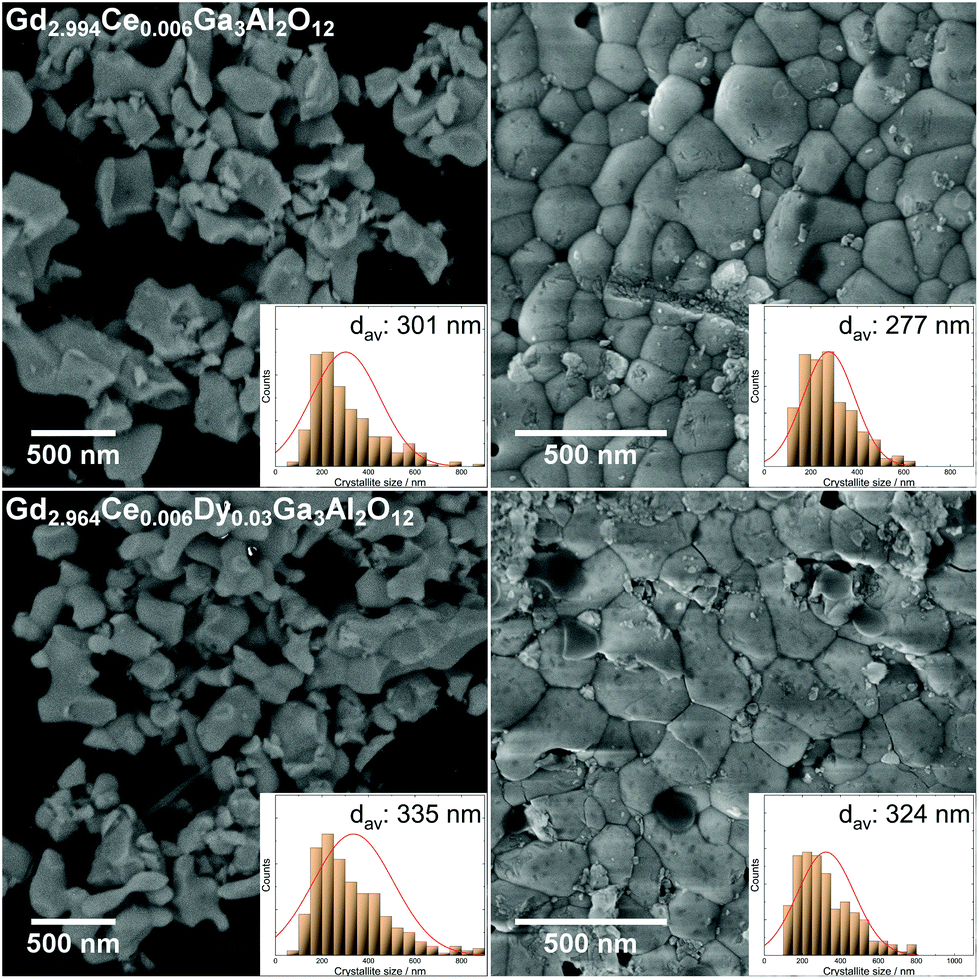
SEM images were taken for the Gd2.994Ce0.006Ga3Al2O12 and Gd2.964Ce0.006Dy0.03Ga3Al2O12 powders and the ceramics sintered of them (Fig. 3). For the powders, it could be seen that the crystallites were in the teens to hundreds of nanometers in size and had oblong shapes. For the ceramics, a slight decrease in the crystallites size could be observed with the high pressure applied during the sintering, which had a great impact on the nanocrystallite surface. It could also be observed that the SEM images showed much bigger crystallites than that calculated using Rietveld refinement. This behavior may be due to the fact that the model used for the calculation based on the broadening and shifting of the XRD lines took a lower share of the strain in the lattice into consideration and connected the broadening more to a decrease in grain size. Underestimating the strains in the lattice during calculation may have led to a false conclusion that the crystallites size was much lower.
 |
| | Fig. 3 SEM images of the Gd2.994Ce0.006Ga3Al2O12 and Gd2.964Ce0.006Dy0.03Ga3Al2O12 powders (left) and ceramics sintered at 8 GPa (right). | |
To check the homogeneity of the ceramics, EDS maps and analysis was performed for ceramics obtained at the highest pressure (Fig. 4). The analysis showed that all the elements were well distributed without visible segregation. The quantitative approach showed that the content of elements in the tested materials was within error limits, consistent with the assumed stoichiometry of the compound (Table 2). It could be seen that the amount of Ce3+ was the same in both ceramics as was assumed in the synthesis. It was also shown that increase in Dy3+ in the structure reduced the amount of Gd3+, which proved the mutual substitution of these elements in the compound. The presence of carbon in the results came from the substrate used in the measurement.
 |
| | Fig. 4 EDS maps of the Gd2.994Ce0.006Ga3Al2O12 and Gd2.964Ce0.006Dy0.03Ga3Al2O12 ceramics sintered at 8 GPa. | |
Table 2 EDS analysis of the elements concentration in the Gd2.994Ce0.006Ga3Al2O12 and Gd2.964Ce0.006Dy0.03Ga3Al2O12 ceramics sintered at 8 GPa
| Element |
Gd2.994Ce0.006Ga3Al2O12 (8 GPa) |
Gd2.964Ce0.006Dy0.03Ga3Al2O12 (8 GPa) |
| Atomic % |
| C |
13.3 |
18.3 |
| O |
57.0 |
54.6 |
| Ga |
11.9 |
10.5 |
| Al |
7.2 |
7.2 |
| Gd |
10.6 |
9.3 |
| Ce |
0.04 |
0.04 |
| Dy |
0 |
0.1 |
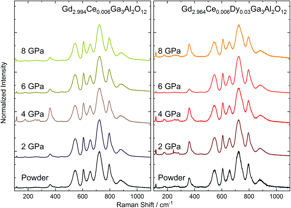
Raman spectroscopy of the Gd2.994Ce0.006Ga3Al2O12 and Gd2.964Ce0.006Dy0.03Ga3Al2O12 ceramics
Due to the presence of Ce3+ ions in the ceramics and their strong luminescence upon 514.5 nm excitation wavelength, the Raman spectra were recorded using an 830 nm laser (Fig. 5). The room-temperature Raman spectra of Gd2.994Ce0.006Ga3Al2O12 and Gd2.964Ce0.006Dy0.03Ga3Al2O12 ceramics measured in the 100–1100 cm−1 Raman shift range presented 13 active Raman modes (Table 3). As the primitive cell of a garnet lattice contains four formula units (80 atoms), from a factor group analysis, there should be 25 Raman-active phonons (3A1g + 8Eg + 14T2g modes).28 The low number of observed modes may be a result of the low resolution caused by performing the measurements at room temperature and the small size of the grains in the ceramics. The low-frequency modes (from 100 to 385 cm−1) were related to librations and translations of the GaO4/AlO4 groups, octahedrally and dodecahedrally coordinated by trivalent cations. The higher frequency modes (440 to 700 cm−1) were assigned to the bending motions of GaO4/AlO4 tetrahedra, for which symmetric and asymmetric internal stretching vibrations were observed at the highest frequencies (above 800 cm−1). The observed modes in the Raman spectra were also interpreted as vibrational modes of the tetrahedral and octahedral strongly coupled units. The experimental values of the Raman shifts were very close to those found for the Gd3Ga2Al3O12 single crystal.29 The position of the phonon peaks remain unchanged but they became broadened with the increase in pressure. Only the ceramics obtained at 2 GPa had FWHM (Full Width at Half Maximum) comparable with the starting powder. Peak broadening of the Raman-active modes of the nanocrystals has been reported in the literature and is related to surface bond contraction, quantum confinement,30 and changes in the size and shape of the particles31 with the decrease in the grain size.32 Furthermore, the broadening may be associated with the substitutional disorder, defects, increased stress, and partial amorphization upon the increased pressure. Also subtle structural changes, including bond lengths and polyhedral distortions, could be expected after applying external pressure. It has to be noted that the structural analysis indicated expansion of the unit cell volume and increase in the distance between the cation and oxygen as a result of the distortion of the cubic polyhedron. For the Raman peak, only broadening without splitting was observed, which suggested a local distortion rather than change in the symmetry of the crystal structure. It is also important that in the structure are present impurities (Ce3+ and Dy3+) with different ionic radii than the substituted Gd3+, which in consequence may simplify the introduction of distortions after applying pressure.33 It should also be noted that the described structure contained tetrahedrons and octahedrons of various sizes due to the partial filling of the nodes by Ga and partially by Al. This means that already for the powder, broadening of the Raman peaks could be observed. As the sintering pressure has a different impact on GaO4/GaO6 and AlO4/AlO6 polyhedral units with the increase in pressure, a growth of the distortion in the structure could be observed, and consequently, a broadening of the Raman peaks.
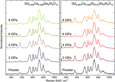 |
| | Fig. 5 Raman spectra of the Gd2.994Ce0.006Ga3Al2O12 and Gd2.964Ce0.006Dy0.03Ga3Al2O12 ceramics sintered at different pressures. | |
Table 3 Energies (cm−1) and symmetry assignments of the Raman-active phonons observed in the Gd2.994Ce0.006Ga3Al2O12 and Gd2.964Ce0.006Dy0.03Ga3Al2O12 ceramics
| Mode |
Gd2.994Ce0.006Ga3Al2O12 2 GPa [This work] |
Gd3Ga2Al3O12 [29] |
Yb3Ga5O12 + Yb3Al5O12 [28] |
| cm−1 |
| Eg |
115 |
117.6 |
111 |
| T2g |
177 |
178.4 |
183 |
| T2g |
252 |
240.7 |
241 |
| T2g |
280 |
273.5 |
272 |
| A1g |
360 |
354.5 |
337 |
| T2g |
385 |
385.5 |
369 |
| Eg |
443 |
425 |
436 |
| A1g |
545 |
526.6 |
529 |
| T2g |
607 |
604 |
624 |
| Eg |
655 |
— |
660 |
| T2g |
725 |
— |
734 |
| T2g |
795 |
— |
769 |
| T2g |
880 |
— |
869 |
Excitation spectra of the Gd2.994Ce0.006Ga3Al2O12 and Gd2.964Ce0.006Dy0.03Ga3Al2O12 ceramics
For the Gd2.994Ce0.006Ga3Al2O12 and Gd2.964Ce0.006Dy0.03Ga3Al2O12 ceramics sintered at different pressures, the excitation spectra were measured (Fig. 6). In both cases, emission was monitored at 560 nm, corresponding to transitions from the lowest 5d1 level to the 2F5/2 level of Ce3+.34 All the spectra showed two broad bands located at about 345 nm (28950 cm−1) and 445 nm (22580 cm−1), attributed to transitions from the 4f ground level of Ce3+ to the lowest 5d2 and 5d1 states,27 respectively. Despite the fact that the concentration of Dy3+ ions was five times higher than Ce3+ and Gd3Ga3Al2O12, doping only with Dy3+ also showed an intense emission band in the region of Ce3+ luminescence at about 580 nm (4F9/2 → 6H13/2 transition),35 no f–f transitions attributed to the Dy3+ ions were noticed in the excitation spectra of the ceramic. The f–f transitions assigned to Dy3+ ions were observed only in the powder. This showed that under 445 nm excitation, the energy was efficiently transferred from the 4I13/2 excited level of Dy3+ to the 5d1 state of Ce3+. At 275, 308, and 314 nm, small sharp peaks attributed to the transitions from 8S7/2 ground level to 6IJ, 6P3/2, and 6P7/2 excited levels of Gd3+ ions (from the matrix) could be observed, respectively.36 It is important to notice that these peaks were much more intense in case of Ce3+ only doped powder samples. In the case of ceramics and co-doping with Dy3+, the intensity of these transitions strongly decreased. As all the excited states of Gd3+ were located in the UV range, they may help in the energy transfer between the conduction band, traps, and excited states of Ce3+.
 |
| | Fig. 6 Excitation spectra of the Gd2.994Ce0.006Ga3Al2O12 and Gd2.964Ce0.006Dy0.03Ga3Al2O12 ceramics sintered at different pressures. | |
The position of the 5d levels of Ce3+ and the distance between them give information on crystal field splitting (Δ21) caused by tetragonal distortion in the cubic structure of the garnet. Therefore for all ceramics, the positions of the 5d1 and 5d2 levels and their FWHM were extracted form Fig. 6 (Table 4). It is known that the crystal field splitting caused by tetragonal distortion is proportional to the red-shift observed in garnets.37 It was observed that for Gd2.994Ce0.006Ga3Al2O12, with the increase in the applied pressure, the bands were shifted toward lower energies (red-shift) and the splitting decreased (the 5d bands get closer to each other). In the case of Gd2.964Ce0.006Dy0.03Ga3Al2O12 ceramics, a red-shift was also observed for both 5d bands, but here the splitting increased after applying higher pressure. The red-shift and higher splitting of the 5d bands resulted from the higher disorder of the surrounding Ce3+ ions displaced from the cubic polyhedron to disordered square anti-prism (dodecahedron).27 A similar behavior was observed by us when the volume of the unit cell was expanded with increasing the Ce3+ concentration.22 It could be also observed that with increasing the pressure, the bands became narrower, which was an effect of increasing the Ce3+/Dy3+–O2− distance and cell volume and as consequence of lowering the probability of non-radiative transitions between luminescent ions.38
Table 4 Positions, full widths at half maximum (FWHM), and splitting of the 5d levels
| p GPa |
5d2 (cm−1) |
FWHM (5d2) (cm−1) |
5d1 (cm−1) |
FWHM (5d1) (cm−1) |
Δ
21 (cm−1) |
|
|
Gd2.994Ce0.006Ga3Al2O12 |
| 0 |
22734 |
2262 |
29036 |
1630 |
6302 |
| 2 |
22583 |
2416 |
28991 |
1632 |
6408 |
| 4 |
22585 |
2448 |
28962 |
1659 |
6377 |
| 6 |
22552 |
2374 |
28952 |
1622 |
6400 |
| 8 |
22555 |
2296 |
28946 |
1608 |
6391 |
|
|
Gd2.964Ce0.006Dy0.03Ga3Al2O12 |
| 0 |
22563 |
2729 |
28995 |
1700 |
6432 |
| 2 |
22595 |
2429 |
28975 |
1638 |
6380 |
| 4 |
22571 |
2386 |
28952 |
1632 |
6381 |
| 6 |
22559 |
2286 |
28951 |
1602 |
6392 |
| 8 |
22542 |
2383 |
28937 |
1634 |
6395 |
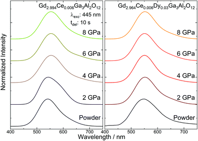
Persistent luminescence spectra of the Gd2.994Ce0.006Ga3Al2O12 and Gd2.964Ce0.006Dy0.03Ga3Al2O12 ceramics
The persistent luminescence spectra of the Gd2.994Ce0.006Ga3Al2O12 and Gd2.964Ce0.006Dy0.03Ga3Al2O12 ceramics were registered 10 s after ceasing 445 nm laser diode irradiation (Fig. 7). For all the ceramics, a broad emission band was observed corresponding to the 5d → 4f Ce3+ transition. The persistent luminescence spectra corresponded to the spectra observed in conventional emission. For both the Gd2.994Ce0.006Ga3Al2O12 and Gd2.964Ce0.006Dy0.03Ga3Al2O12 ceramics, a slight shift of the band maximum toward lower energies (red-shift) and a narrowing of the emission band were noticed. As the emission wavelength is very sensitive to the crystallographic environment of Ce3+ ions, the red-shift of the band and decrease in FWHM may be explained by the change in Δ21 splitting of the 5de levels caused by the tetragonal distortion for Ce3+ in the cubic garnet structure.37 It is interesting that under UV excitation (266 nm), both the Gd2.994Ce0.006Ga3Al2O12 and Gd2.964Ce0.006Dy0.03Ga3Al2O12 ceramics showed no or only very weak persistent luminescence. This was related to the fact that 445 nm excitation wavelength may capture and release the electrons from traps much faster and more efficiently due to a direct tunneling process.39
 |
| | Fig. 7 Persistent luminescence spectra of the Gd2.994Ce0.006Ga3Al2O12 and Gd2.964Ce0.006Dy0.03Ga3Al2O12 ceramics sintered at different pressures. | |
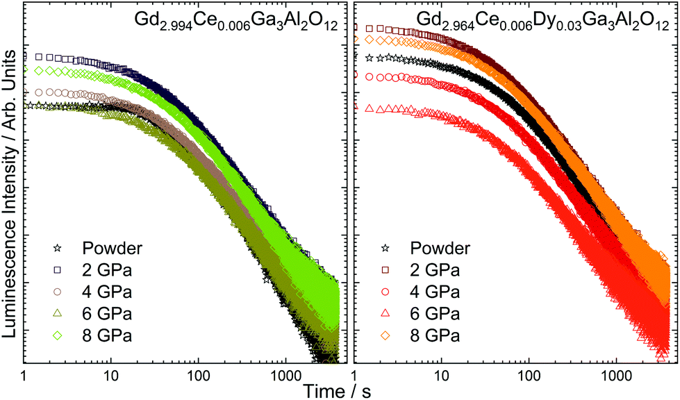
A fading time of the persistent luminescence observed in the Ce3+-doped and Dy3+-co-doped ceramics was registered after ceasing 445 nm irradiation (Fig. 8). In all cases, the decay was non-exponential, suggesting the presence of traps with different energies. To obtain the best fit, the curves were fitted using three decays (the biexponential formula was used only for Gd2.994Ce0.006Ga3Al2O12):
| y = y0 + A1e−x/τ1 + A2e−x/τ2 + A3e−x/τ3 |
 |
| | Fig. 8 Fading time curves registered for the Gd2.994Ce0.006Ga3Al2O12 and Gd2.964Ce0.006Dy0.03Ga3Al2O12 ceramics sintered at different pressures. | |
Three decays were used for the calculations, assuming the existence of carrier trapping sites with distributed energy levels and different carrier transport rates. The first decay (τ1) was the shortest and was associated with shallow traps. The emission from the these traps was responsible for the bright, intense luminescence in the first 30 s after ceasing irradiation. It was observed that for the ceramics sintered in the whole range of pressure, it was about 25–30 s (Table 5). The next two decays were associated with the medium (τ2) and deep traps (τ3). These traps were responsible for the observation of persistent luminescence for longer times after switching off the irradiation source, as the energy needed for detrapping the carriers was higher. It was interesting that only for the powders singly doped with Ce3+, it was possible to fit the curve with two decays. This was because for the ceramics and for the Dy3+-co-doped sample, the decay curves had to be fitted with third decays, proving that the co-dopant and the pressure applied during sintering were responsible for the formation of additional traps. It could be observed that increasing the sintering pressure prolonged both decays, but at the highest pressure, the time became shorter. This may be related to the fact, that after applying 8 GPa, the deep traps have a higher share in the overall persistent luminescence and their energies are too high to effectively release the electrons.
Table 5 Fading time of persistent luminescence of the Gd2.994Ce0.006Ga3Al2O12 and Gd2.964Ce0.006Dy0.03Ga3Al2O12 ceramics
| Pressure (GPa) |
τ
1 (s) |
τ
2 (s) |
τ
3 (s) |
| Gd2.994Ce0.006Ga3Al2O12 |
| 0 |
47 |
|
331 |
| 2 |
26 |
102 |
554 |
| 4 |
29 |
112 |
584 |
| 6 |
30 |
117 |
615 |
| 8 |
27 |
108 |
585 |
| Gd2.964Ce0.006Dy0.03Ga3Al2O12 |
| 0 |
29 |
110 |
583 |
| 2 |
24 |
98 |
552 |
| 4 |
28 |
106 |
587 |
| 6 |
30 |
118 |
613 |
| 8 |
26 |
103 |
581 |
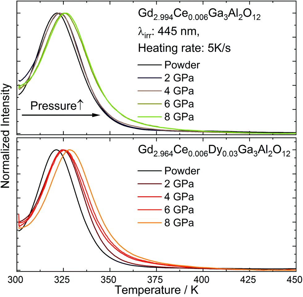
Thermoluminescence (TL) of Gd2.994Ce0.006Ga3Al2O12 and Gd2.964Ce0.006Dy0.03Ga3Al2O12 ceramics
The ceramics and starting powder were irradiated for 5 min using 450 nm laser diode (1 mW) and after switching off the excitation the thermoluminescence (TL), glow curves were registered with the heating rate of 5 K s−1 (Fig. 9). The glow curves showed a non-uniformly broadened band that could be fitted using two peaks in the case of the powders and three peaks for the ceramics. The need to fit the TL curve measured for the ceramics with an additional peak compared to the powders, proved that the applied pressure increased the distribution of traps (multiple nonequivalent traps in the crystal distributed at different distances from Ce3+), which allowed for an easier transfer of electrons from the traps to the conduction band. It could also be noticed that after applying the pressure, the TL peaks were shifted toward higher temperatures and became broader with the increase in pressure. Since deeper traps require more energy to release electrons, this process is slower and the persistent luminescence can be observed for longer.
 |
| | Fig. 9 Thermoluminescence (TL) glow curves registered for Gd2.994Ce0.006Ga3Al2O12 and Gd2.964Ce0.006Dy0.03Ga3Al2O12 ceramics sintered at different pressure. | |
The glow curves were fitted using OriginLab 2019b software. The positions of the maxima and share of the glow curves and traps energies calculated for all the ceramics are presented in Table 6. For estimation of the traps depth, the simple analysis proposed by Urbach was applied.40 The model involved large simplifications, including the assumption that charge carriers recombine with luminescent centers and are not caught again by another trap. However, as this was applied with the same conditions for all samples, it allowed comparing the impact of the co-doping and sintering pressure on the change in the traps’ energy. It could be observed that with co-doping with Dy3+, the energy of the traps slightly increased. It could be also observed that for the samples subjected to very high pressure, the depth and distribution of the traps also increased. An increase in the trap depth with the increase in the pressure was observed by Ueda et al.20 The higher energy of the traps upon raising the pressure is associated with the increase in the first conduction band (CB) after applying the pressure.41 As the distance between the bottom of the CB and the traps related to the excited states of lanthanides grows, the energy needed to release the traps also increases. Another important aspect to consider is the contribution of the various type of traps in overall thermoluminescence. The analysis of the curves showed that the proportion of shallow, medium, and deep traps changed depending on the applied pressure. It could be seen that in the case of the ceramics doped only with cerium, the distribution of shallow and medium traps was at a similar level, and the share of deep traps increased slightly with the pressure. In the case of the ceramics co-doped with cerium and dysprosium, the changes were more complex. Also here an increase in the share of deep traps in the overall thermoluminescence could be noticed with the increase in the pressure, while in this case, for the highest pressures, the share of intermediate traps also increased. This may indicate an interaction between the pressure-induced traps and those resulting from the introduction of Dy3+ into the matrix.
Table 6 Trap depth energy calculated from TL glow-curves of the Gd2.994Ce0.006Ga3Al2O12 and Gd2.964Ce0.006Dy0.03Ga3Al2O12 ceramics
| Pressure (GPa) |
TL parameters |
| Gd2.994Ce0.006Ga3Al2O12 |
| 0 |
T/K |
|
320 |
335 |
|
E
a/eV |
|
0.64 |
0.67 |
| Share/% |
|
98.9 |
1.1 |
| 2 |
T/K |
300 |
323 |
335 |
|
E
a(lp)/eV |
0.60 |
0.65 |
0.67 |
| Share/% |
56.6 |
40.5 |
2.9 |
| 4 |
T/K |
303 |
323 |
340 |
|
E
a/eV |
0.61 |
0.65 |
0.68 |
| Share/% |
65.1 |
30.7 |
4.2 |
| 6 |
T/K |
296 |
325 |
336 |
|
E
a/eV |
0.59 |
0.65 |
0.67 |
| Share/% |
64.6 |
30.2 |
5.2 |
| 8 |
T/K |
294 |
326 |
340 |
|
E
a(hp)/eV |
0.59 |
0.65 |
0.68 |
| Share/% |
60.7 |
32.7 |
6.7 |
| Gd2.964Ce0.006Dy0.03Ga3Al2O12 |
| 0 |
T/K |
|
321 |
335 |
|
E
a/eV |
|
0.64 |
0.67 |
| Share /% |
|
76.9 |
23.1 |
| 2 |
T/K |
292 |
325 |
344 |
|
E
a(lp)/eV |
0.58 |
0.65 |
0.69 |
| Share/% |
77.1 |
20.1 |
2.8 |
| 4 |
T/K |
293 |
325 |
341 |
|
E
a/eV |
0.59 |
0.65 |
0.68 |
| Share/% |
71.5 |
23.0 |
5.5 |
| 6 |
T/K |
297 |
325 |
334 |
|
E
a/eV |
0.59 |
0.65 |
0.67 |
| Share/% |
70.0 |
18.1 |
12.0 |
| 8 |
T/K |
305 |
329 |
347 |
|
E
a (hp)/eV |
0.61 |
0.66 |
0.69 |
| Share/% |
63.8 |
28.3 |
7.9 |
The nature of the traps involved in the persistent luminescence process should be considered on the basis of the following facts. The Ce3+ and Dy3+ dopants have the same valence as the substituted Gd3+ ion, so no charge compensation is required and the energy traps should be related to other intrinsic defects. As the calcination of the powders and ceramic sintering were conducted in an oxygen atmosphere, it may lead to the introduction to the matrix of intrinsic defects of oxygen vacancies  with positive charges. It may also oxidize part of the Ce3+ ions, with the consequence that in the matrix they will coexist in a mixed-valence state (Ce3+, Ce4+). Another type of trap that should be considered in the studied ceramics is the electron catcher, which is Dy3+. Joos et al. showed also that the presence of Dy3+ could mediate the persistent luminescence, because a fraction of the Dy3+ is reduced to Dy2+ along with the oxidation of Eu2+ to Eu3+.23 For co-doped ceramics, a similar process may occur, where during the irradiation part, Ce3+ is oxidized to Ce4+, while the redox partner Dy3+ gets reduced.
Mechanism of the persistent luminescence
Based on the results presented above, a mechanism for the persistent luminescence in ceramics obtained at different pressures can be constructed (Fig. 10). The mechanism is based on the considerations described earlier by us [22] with changes induced by applying pressure added. As the energy gap increased with the increase in the applied pressure, the distance between the traps and the bottom of the conduction band also increased. This resulted in an increase in the energy needed to release the carriers from the traps. As shown in the TL spectra, both types of ceramics showed an increase in the electron trap depth by pressure due to the increase in the CB bottom. The energies of the 5d bands were taken from the excitation spectra, while the energy of the ground level was estimated from the emission band (about 1.8 eV difference between the bottom of the 5d state and the ground level) and the host referred binding energy of electrons for Ce3+ (ref. 42) (the Ce3+ ground level was about 2 eV above the top of the valence band of the host), while the trap depths were calculated from the thermoluminescence measurements. Under 445 nm irradiation, the electrons are excited from the ground state to the 5d level (1). Part of the electrons from the excited Ce3+ 5d level return directly to their ground state, leading to conventional yellow-green luminescence. Another part may be transferred directly to the defects (electron traps) due to a tunneling process39 (2). However, since changes in the persistent luminescence were observed with the increase in sintering pressure, the electron transfer through the conduction band should also be taken into account, where the distance from the trap depends on the pressure applied in the preparation process. In this case, the electrons excited from the ground level to the 5d state due to the relatively small thermal activation energy43 are transferred through the conduction band to the traps (3). The activation energies (Ea(lp) and Ea(hp)) calculated from the TL glow curves were in the range of 0.58 to 0.69 eV (below the CB), which show that these defects are able to capture and release the electrons at room temperature. The continuous excitation fills the shallow, medium, and deep traps with carriers, and after ceasing the irradiation under thermal stimulation at room temperature, the electrons are released from the traps. Part of the carriers are transferred back through the CB (3) to the 5d levels and relax to the lowest 5d1 and then to ground state, thus giving the persistent luminescence (4). Simultaneously, the electrons captured in deeper traps may be released to the nearby Ce3+ excited levels through direct tunneling (2), which also leads to the persistent luminescence. As in the ceramics sintered at higher pressure, the traps were deeper (located lower to the bottom of the CB), which may promote direct energy transfer from the trap to the excited 5d1 level (2), thus emptying the deeper traps and meaning persistent luminescence can be observed for longer.
 |
| | Fig. 10 Mechanism of the persistent luminescence in ceramics sintered at different pressures. | |
Conclusions
The pressure-dependence of the Ce3+: 5d1–4f persistent luminescence properties were investigated in Gd2.994Ce0.006Ga3Al2O12 and Gd2.964Ce0.006Dy0.03Ga3Al2O12 nanoceramics. The phonon peaks were broadened with the increase in pressure, which was related to surface bond contraction, the quantum confinement, and changes in the shape of the particles with the decrease in the grain size. The 5d1 and 5d2 were red shifted and the splitting increased after applying higher pressure as a result of the higher disorder of the surrounding of Ce3+. The 5d1–4f persistent luminescence spectra similar to the excitation spectra were red shifted with the pressure confirming increasing disorder in the structure of the ceramics. Also an increase in the fading time of persistent luminescence with the increase in the sintering pressure was observed, which was related to the increase in the CB bottom and the deeper traps after applying pressure. The creation of deeper traps were confirmed by thermoluminescence measurements. Based on the obtained results, a mechanism for the persistent luminescence was constructed and discussed.
Conflicts of interest
There are no conflicts to declare.
Acknowledgements
This work was supported by the National Science Centre, Poland under grant no. 2017/26/D/ST5/00904. Author would like to thank M.Sc. Eng. Daniela Kujawa for powder synthesis, Dr Robert Tomala for ceramic sintering, M.Sc. Andrius Pakalniškis and Dr Damian Szymański for technical assistance in SEM imaging and Dr Vitalii Boiko for thermoluminescence measurements.
Notes and references
- J. Hölsä, Electrochem. Soc. Interface, 2009,(Winter), 42–45 CrossRef.
- K. Van den Eeckhout, P. F. Smet and D. Poelman, Materials, 2010, 3, 2536–2566 CrossRef CAS.
- T. Matsuzawa, J. Electrochem. Soc., 1996, 143, 2670 CrossRef CAS.
- L. Huang, L. Lin, W. Xie, Z. Qiu, H. Ni, H. Liang, Q. Tang, L. Cao, J. X. Meng and F. Li, Chem. Mater., 2020, 32, 5579–5588 CrossRef CAS.
- V. Castaing, A. D. Sontakke, J. Xu, A. J. Fernández-Carrión, C. Genevois, S. Tanabe, M. Allix and B. Viana, Phys. Chem. Chem. Phys., 2019, 21, 19458–19468 RSC.
- Y. Zhao, J. Du, X. Wu, Y. Wang and D. Poelman, J. Lumin., 2020, 220, 117035 CrossRef CAS.
- W. Huang, X. Gong, R. Cui, X. Li, L. Li, X. Wang and C. Deng, J. Mater. Sci.: Mater. Electron., 2018, 29, 10535–10541 CrossRef CAS.
- H. Lin, T. Yu, G. Bai, M. K. Tsang, Q. Zhang and J. Hao, J. Mater. Chem. C, 2016, 4, 3396–3402 RSC.
- J. Xu, S. Tanabe, A. D. Sontakke and J. Ueda, Appl. Phys. Lett., 2015, 107, 081903 CrossRef.
- N. S. M. Viswanath, G. K. Grandhi, H. J. Kim, Y. Zhuang, R. J. Xie and W. Im, Appl. Mater. Today, 2020, 18, 100518 CrossRef.
- L. C. V. Rodrigues, J. Hölsä, M. Lastusaari, M. C. F. C. Felinto and H. F. Brito, J. Mater. Chem. C, 2014, 2, 1612–1618 RSC.
- D. Dutczak, A. Milbrat, A. Katelnikovas, A. Meijerink, C. Ronda and T. Jüstel, J. Lumin., 2012, 132, 2398–2403 CrossRef CAS.
- X. Xu, X. Yu, D. Zhou and J. Qiu, J. Solid State Chem., 2013, 206, 66–68 CrossRef CAS.
- V. Boiko, M. Markowska, L. Consentino, M. L. Saladino and D. Hreniak, Opt. Mater., 2020, 107, 109956 CrossRef CAS.
- S. Zhou, B. Lou, L. Lou, J. Wen and M. Yin, Opt. Mater., 2020, 111, 110647 CrossRef.
- X. Fan, X. Xu, X. Yu, W. Chen, D. Zhou and J. Qiu, Mater. Res. Bull., 2018, 99, 398–402 CrossRef CAS.
- L. C. V. Rodrigues, H. F. Brito, J. Hölsä, R. Stefani, M. C. F. C. Felinto, M. Lastusaari, T. Laamanen and L. A. O. Nunes, J. Phys. Chem. C, 2012, 116, 11232–11240 CrossRef CAS.
- X. Zhang, C. Cao, C. Zhang, S. Xie, G. Xu, J. Zhang and X. Wang, Mater. Res. Bull., 2010, 45, 1832–1836 CrossRef CAS.
- Y. Katayama, J. Ueda and S. Tanabe, J. Lumin., 2014, 148, 290–295 CrossRef CAS.
- J. Ueda, M. Harada, S. Miyano, A. Yamada and S. Tanabe, Phys. Chem. Chem. Phys., 2020, 22, 19502–19511 RSC.
- P. Głuchowski, R. Tomala, R. Kowalski, O. Ignatenko, M. E. Witkowski, W. Drozdowski, W. Stręk, W. Ryba-Romanowski and P. Solarz, Ceram. Int., 2019, 45, 21870–21877 CrossRef.
- P. Głuchowski and K. Rajfur, Inorg. Chem., 2021, 60, 18777–18788 CrossRef PubMed.
- J. J. Joos, K. Korthout, L. Amidani, P. Glatzel, D. Poelman and P. F. Smet, Phys. Rev. Lett., 2020, 125, 033001 CrossRef CAS.
- M. Galceran, M. C. Pujol, M. Aguiló, F. Díaz, M. Aguiló and F. Díaz, J. Sol-Gel Sci. Technol., 2007, 42, 79–88 CrossRef CAS.
- R. Fedyk, D. Hreniak, W. Łojkowski, W. Stręk, H. Matysiak, E. Grzanka, S. Gierlotka and P. Mazur, Opt. Mater., 2007, 29, 1252–1257 CrossRef CAS.
-
T. Degen, M. Sadki, E. Bron, U. König and G. Nénert, in Powder Diffraction, Cambridge University Press, 2014, vol. 29, pp. S13–S18 Search PubMed.
- J. Ueda and S. Tanabe, Opt. Mater.: X, 2019, 1, 100018 CAS.
- J.-J. Song, P. B. Klein, R. L. Wadsack, M. Selders, S. Mroczkowski and R. K. Chang, J. Opt. Soc. Am., 1973, 63, 1135 CrossRef CAS.
- K. Papagelis, J. Arvanitidis, E. Vinga, D. Christofilos, G. A. Kourouklis, H. Kimura and S. Ves, J. Appl. Phys., 2010, 107, 113504 CrossRef.
- Y. Gao and P. Yin, Sci. Rep., 2017, 7, 1–4 CrossRef PubMed.
- A. V. Igo, Opt. Spectrosc., 2016, 120, 529–533 CrossRef CAS.
- A. Lukowiak, R. J. Wiglusz, M. Maczka, P. Gluchowski and W. Strek, Chem. Phys. Lett., 2010, 494, 4–6 CrossRef.
- T. H. Nguyen, T. M. H. Nguyen, B. Kang, B. Cho, M. Han, H. J. Choi, M. Kong, Y. Lee and I. S. Yang, J. Raman Spectrosc., 2019, 50, 1661–1671 CrossRef CAS.
- J. Ueda, S. Miyano and S. Tanabe, ACS Appl. Mater. Interfaces, 2018, 10, 20652–20660 CrossRef CAS PubMed.
- R. Lisiecki, P. Solarz, T. Niedźwiedzki, W. Ryba-Romanowski and M. Głowacki, J. Alloys Compd., 2016, 689, 733–739 CrossRef CAS.
- W. Drozdowski, M. E. Witkowski, P. Solarz, P. Głuchowski, M. Głowacki and K. Brylew, Opt. Mater., 2018, 79, 227–231 CrossRef CAS.
- P. Dorenbos, J. Lumin., 2013, 134, 310–318 CrossRef CAS.
- J. Collins, ECS J. Solid State Sci. Technol., 2015, 5, R3170 CrossRef.
- D. Jia and W. M. Yen, J. Electrochem. Soc., 2003, 150, H61 CrossRef CAS.
- F. Urbach, Sitzungsber. Akad. Wiss. Wien, 1930, 139, 363 Search PubMed.
- V. Monteseguro, P. Rodríguez-Hernández, V. Lavín, F. J. Manjón and A. Muñoz, J. Appl. Phys., 2013, 113, 183505 CrossRef.
- P. Dorenbos and E. G. Rogers, ECS J. Solid State Sci. Technol., 2014, 3, R150–R158 CrossRef CAS.
- V. Babin, M. Buryi, V. Chlan, Y. Fomichov, K. Kamada, V. V. Laguta, M. Nikl, J. Pejchal, H. Štěpánková, A. Yoshikawa, Y. Zagorodniy and S. Zazubovich, J. Lumin., 2018, 200, 141–150 CrossRef CAS.
|
| This journal is © The Royal Society of Chemistry 2022 |
Click here to see how this site uses Cookies. View our privacy policy here. 
 Open Access Article
 This Open Access Article is licensed under a Creative Commons Attribution-Non Commercial 3.0 Unported Licence


 with positive charges. It may also oxidize part of the Ce3+ ions, with the consequence that in the matrix they will coexist in a mixed-valence state (Ce3+, Ce4+). Another type of trap that should be considered in the studied ceramics is the electron catcher, which is Dy3+. Joos et al. showed also that the presence of Dy3+ could mediate the persistent luminescence, because a fraction of the Dy3+ is reduced to Dy2+ along with the oxidation of Eu2+ to Eu3+.23 For co-doped ceramics, a similar process may occur, where during the irradiation part, Ce3+ is oxidized to Ce4+, while the redox partner Dy3+ gets reduced.