
 Open Access Article
 This Open Access Article is licensed under a
 Creative Commons Attribution 3.0 Unported Licence
The crystal and defect structures of polar KBiNb2O7†
Subhadip
Mallick
a,
Weiguo
Zhang
b,
Maria
Batuk
 c,
Alexandra S.
Gibbs
d,
Joke
Hadermann
c,
P. Shiv
Halasyamani
b and
Michael A.
Hayward
*a
c,
Alexandra S.
Gibbs
d,
Joke
Hadermann
c,
P. Shiv
Halasyamani
b and
Michael A.
Hayward
*a
aDepartment of Chemistry, University of Oxford, Inorganic Chemistry Laboratory, South Parks Road, Oxford, OX1 3QR, UK. E-mail: michael.hayward@chem.ox.ac.uk
bDepartment of Chemistry, University of Houston, 112 Fleming Building, Houston, Texas 77204-5003, USA
cEMAT, University of Antwerp, Groenenborgerlaan 171, B-2020 Antwerp, Belgium
dISIS Facility, Rutherford Appleton Laboratory, Chilton, Oxon OX11 0QX, UK
First published on 5th January 2022
Abstract
KBiNb2O7 was prepared from RbBiNb2O7 by a sequence of cation exchange reactions which first convert RbBiNb2O7 to LiBiNb2O7, before KBiNb2O7 is formed by a further K-for-Li cation exchange. A combination of neutron, synchrotron X-ray and electron diffraction data reveal that KBiNb2O7 adopts a polar, layered, perovskite structure (space group A11m) in which the BiNb2O7 layers are stacked in a (0, ½, z) arrangement, with the K+ cations located in half of the available 10-coordinate interlayer cation sites. The inversion symmetry of the phase is broken by a large displacement of the Bi3+ cations parallel to the y-axis. HAADF-STEM images reveal that KBiNb2O7 exhibits frequent stacking faults which convert the (0, ½, z) layer stacking to (½, 0, z) stacking and vice versa, essentially switching the x- and y-axes of the material. By fitting the complex diffraction peak shape of the SXRD data collected from KBiNb2O7 it is estimated that each layer has approximately a 9% chance of being defective – a high level which is attributed to the lack of cooperative NbO6 tilting in the material, which limits the lattice strain associated with each fault.
Introduction
Solid state compounds which exhibit non-centrosymmetric (NCS) crystal structures have been widely studied because they can exhibit physical properties such as ferroelectricity, piezoelectricity and second harmonic generation (SHG) which are forbidden by symmetry to centrosymmetric phases.1,2 However, the preparation of acentric solid phases is challenging, principally because NCS crystal structures tend to be thermodynamically unstable with respect to centric alternatives, as these latter high symmetry structures exhibit more efficient packing.The conventional method used to stabilize acentric structures is to make use of an electronic instability of a chemical subunit to break the inversion symmetry of the underlying centrosymmetric framework of a material. For example, instabilities such as the second-order Jahn–Teller (SOJT) distortion of octahedrally coordinated d0 transition metal cations (e.g. Ti4+ in BaTiO3),3–6 or the ‘off-centring’ distortions of ns2 post-transition elements, often interpreted as stereoactive lone pairs (e.g. Bi3+ in BiFeO3),7–12 have been widely used to stabilize NCS crystal structures in complex oxide materials. However, the requirement to include these ‘polar chemical species’ limits the chemical constitution of NCS materials and makes it hard to include other properties such as magnetism in acentric phases.13
There has been much interest recently in a new class of acentric materials, the ‘hybrid-improper’ ferroelectrics, because their NCS crystal structures are not stabilized by specific polar chemical subunits. Instead the polar ground states of hybrid-improper ferroelectric phases are established by the presence of two non-polar structural distortion modes, which couple to, and stabilize, a third polar distortion mode.14,15 This trilinear coupling of modes can stabilize polar NCS crystal structures without the assistance of local electronic instabilities, so offers the prospect of broadening the chemistry of NCS materials. It should be noted that the resulting polar materials are often referred to as ‘hybrid-improper ferroelectric phases’ because the ferroelectric polarisation which emerges at the paraelectric-to-ferroelectric phase transition of these materials need not be the primary order parameter of this phase transition.
The hybrid-improper mechanism has been observed to be responsible for the polar ground states of a number of A3B2O7n = 2 Ruddlesden-Popper oxide phases. In these systems two low-energy, cooperative tilting distortions of the BO6 octahedra combine to stabilize a third polar distortion mode (usually a polar displacement of the A-cations) to yield polar and potentially ferroelectric phases. Thus, the polar ground state structures of (Ca, Sr)3Ti2O7,16 (Ca, Sr)3Sn2O7![[thin space (1/6-em)]](https://www.rsc.org/images/entities/char_2009.gif) 17 Sr3Zr2O7,18 and Ca3Mn2O719 have been attributed to the hybrid-improper stabilization mechanism.
17 Sr3Zr2O7,18 and Ca3Mn2O719 have been attributed to the hybrid-improper stabilization mechanism.
Layered perovskite oxides based on the A′AB2O7n = 2 Dion-Jacobson framework have also been shown to exhibit polar structures stabilized by trilinear coupling.20 For example, CsNdM2O7 and RbNdM2O7 (M = Nb, Ta) have been observed to adopt polar ground states, with ferroelectric switching reported for the two niobium phases.21–23
The extensive cation exchange chemistry exhibited by Dion-Jacobson phases allows a range of metastable layered perovskite phases to be prepared.24 For example, the Rb+ cations in RbNdM2O7 (M = Nb, Ta) can be exchanged for K+, Na+ or Li+, allowing the whole range of A′NdNb2O7 (A′ = Cs, Rb, K, Na, Li) materials to be investigated.25,26 This reveals that LiNdM2O7 and NaNdM2O7 adopt pseudo Ruddlesden-Popper structures with the lithium materials exhibiting polar ground states stabilized by trilinear coupling, in contrast to the centrosymmetric structures of the sodium phases – a difference which can be attributed to the differing cation ordering patterns present in the contrasting materials.25 KNdNb2O7 and KNdTa2O7 adopt layered perovskite structures with an unusual (0, ½, z) stacking of the perovskite sheets which are separated by 6-coordinate prismatic K+ cations.26 Structural analysis reveals these KNdM2O7 materials are polar, but in this instance the acentric ground state is stabilized by a ‘conventional’ SOJT distortion of the MO6 units.
The conventional polar distortions of the KNdM2O7 phases highlight the fact that many of the complex oxides which exhibit hybrid-improper polar ground states also contain ‘polar chemical species’, such as octahedrally coordinated d0 transition-metal cations. Thus, in principle, these compounds could adopt polar structures stabilized by the SOJT distortions of these polar chemical groups, which are in competition with the observed polar structures stabilized by trilinear coupling. This competition can be seen clearly in the two pseudo Ruddlesden-Popper phases Li2La(TaTi)O7 and Na2La(TiTa)O7 in which the polar distortion of the lithium phase is stabilized by trilinear coupling, in contrast to that of the sodium phase which is consistent with a SOJT stabilization mechanism.27
Recently, to investigate the effect of including ns2 post-transition metal cations in hybrid-improper polar phases, we reported the structures of NaBiNb2O7 and LiBiNb2O7 which were prepared by cation exchange from the Dion-Jacobson phase RbBiNb2O7.28 Here we complete the A′BiNb2O7 series with an investigation of KBiNb2O7.
Experimental
Synthesis
Samples of KBiNb2O7 were prepared by first synthesising RbBiNb2O7, converting this material to LiBiNb2O7via Li-for-Rb cation exchange,28 and finally forming KBiNb2O7via a K-for-Li cation exchange reaction. Specifically, polycrystalline samples of RbBiNb2O7 were prepared by a solid-state ceramic synthesis method from suitable stoichiometric ratios of Bi2O3 (99995%) and Nb2O5 (99.9985%, dried at 900 °C), which were ground together in an agate pestle and mortar and combined with 50% excess (to compensate for the loss due to volatilization at high temperature) of Rb2CO3 (99.8%). These mixtures were then placed in open-ended silica tubes and heated at 600 °C in air for 12 h. The samples were then reground and heated at 1000 °C for 6 h then 12 h and 2 further periods of 4 h with regrinding between heating cycles. Finally, the powder samples were washed with distilled water to remove any excess rubidium oxide and then dried in air at 120 °C for 12 h. This heating regime was required to avoid the formation of BiNbO4.
LiBiNb2O7 was synthesized as described previously28 by reacting RbBiNb2O7 with 10 mole-equivalents of LiNO3 (99.98%) in open ended silica tubes at 360 °C in air, for two periods of 48 h. Between heating cycles, samples were washed with distilled water, dried for 12 h at 120 °C in air and then mixed with a further 10 mole-equivalents of LiNO3. After the final heating step, all samples were washed with distilled water to remove the LiNO3 and then dried for 12 h at 120 °C in air.
KBiNb2O7 was synthesized by reacting LiBiNb2O7 with 10 mole-equivalents of KNO3 (99.995%) in open ended silica tubes at 400 °C in air, for two periods of 48 h. Between heating cycles, samples were washed with distilled water, dried for 12 h at 120 °C in air and then mixed with a further 10 mole-equivalents of KNO3. After the final heating step, all samples were washed with distilled water to remove the excess KNO3 and then dried for 12 h at 120 °C in air.
Characterisation
X-ray powder diffraction data were collected using a PANalytical X′pert diffractometer incorporating an X′celerator position-sensitive detector (monochromatic Cu Kα1 radiation). High-resolution synchrotron X-ray powder diffraction (SXRD) data were collected using the I11 instrument at the Diamond Light Source Ltd. Diffraction patterns were collected using Si-calibrated X-rays with an approximate wavelength of 0.825 Å from samples, sealed in 0.3 mm diameter borosilicate glass capillaries. Time-of-flight neutron powder diffraction (NPD) data were collected using the HRPD diffractometer at the ISIS neutron source from the samples loaded in 8 mm vanadium cans. Rietveld refinements were performed using the TOPAS Academic (V6).29 The particle-size dependent second harmonic generation (SHG) response of samples was measured by grinding sintered pellets of material and then sieving the resulting powders into distinct particle size ranges (<20, 20–45, 45–63, 63–75, 75–90, 90–125 μm). SHG intensity was then recorded from each particle size range and compared to a standard sample of KH2PO4 (KDP) in the same particle size ranges. No index matching fluid was used in any of the experiments. A detailed description of the experimental setup and process has been reported previously.30Electron diffraction (ED) patterns were acquired on a FEI Tecnai transmission electron microscope (TEM) operated at 200 kV. High angle annular dark field (HAADF) scanning transmission electron microscopy (STEM) images were acquired using a probe aberration corrected FEI Titan 80–300 “cubed” microscope operated at 300 kV. Samples for TEM analysis were prepared in an argon-filled glove box by dipping a copper TEM grid into the ground dry powder. The grids were then transferred into the microscope using a vacuum transfer holder.
Simulated HAADF-STEM images were calculated using the QSTEM software.31
Results
Synthesis of KBiNb2O7
KBiNb2O7 could not be prepared by direct high-temperature synthesis. Reaction of K2CO3, Bi2O3 and Nb2O5 at 1100 °C primarily yielded the tetragonal tungsten bronze phase K2BiNb5O15,32 indicating that the desired layered perovskite phase is metastable with respect to a mixture of the tetragonal tungsten bronze phase and Bi2O3. KBiNb2O7 could be prepared via K-for-Li cation exchange of LiBiNb2O7, as described above. It should be noted that unlike KNdNb2O7,26 KBiNb2O7 could not be prepared via direct K-for-Rb cation exchange of the corresponding RbANb2O7 phase, with the synthesis of KBiNb2O7 only achieved via the reaction sequence RbBiNb2O7 to LiBiNb2O7 to KBiNb2O7, as LiBiNb2O7 itself can only be prepared via cation exchange from RbBiNb2O7.28Structural characterisation of KBiNb2O7
High resolution SXRD and NPD data collected from KBiNb2O7 was initially indexed using a monoclinic unit cell (a = 3.847 Å, b = 3.840 Å, c = 22.193 Å, γ = 90.80°). This unit cell is consistent with the aristotype unit cell of a (0, ½, z) stacked n = 2 layered perovskite.33–35 However, on close inspection a series of small diffraction peaks were observed (Fig. S1, ESI†) which could only be indexed using an expanded unit cell (a = 7.694 Å, b = 3.840 Å, c = 22.193 Å, γ = 90.80°) which is an a′ ≈ 2a, b′ ≈ b, c′ ≈ c geometric expansion of the aristotype unit cell, with reflection conditions consistent with an A-centred unit cell.Electron diffraction (ED) patterns collected from KBiNb2O7 (Fig. 1) show streaking along c*, indicative of stacking faults in the material (vide infra). Analysis of these patterns confirms the a′ ≈ 2a, b′ ≈ b, c′ ≈ c unit cell obtained from the SXRD and NPD data, with reflection conditions consistent with A-centring. Particle-size dependent SHG data (Fig. 2) reveals KBiNb2O7 has an SHG activity which is approximately 1.5 times that of KDP, and thus has a non-centrosymmetric crystal structure.
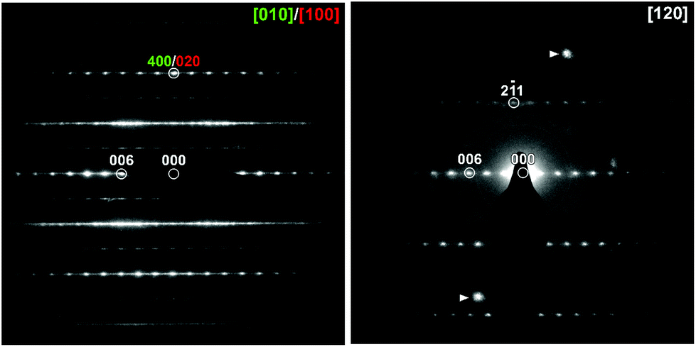 | ||
| Fig. 1 Electron diffraction patterns collected from KBiNb2O7. The presence of ‘axis-switch’ stacking faults means the [010] and [100] zone axes are superimposed. The indicated spots in the [120] zone are due to overlap with another crystal. | ||
 | ||
| Fig. 2 SHG activity as a function of particle size for KBiNb2O7 compared to a KDP standard. | ||
Combining the information above, we can deduce that KBiNb2O7 adopts a crystal structure described in an A-centred, non-centrosymmetric monoclinic space group. This gives 3 candidates: A11a (#9), A11m (#8) and A112 (#5) with unit cell settings chosen to preserve the z-axis as the stacking direction. Structural models were constructed in these three space groups and refined against the NPD data collected at room temperature. The diffraction data show strongly hkl-dependent peak shapes as shown in Fig. S2 in the ESI,† which arises from stacking faults in the material as discussed later. At this stage of the structural refinement no attempt was made to include stacking faults in the structural model, with the hkl-dependent peak width modelled by a 6th order spherical harmonic,36 which led to a significant improvement in the fit to the data.
A comparison of fitting statistics reveals that the A112 model fits the data poorly (wRp = 10.2) and yields a chemically implausible structure for KBiNb2O7, so this model was rejected. The fitting parameters from the refinement of A11m (wRp = 8.43) and A11a (wRp = 8.50) symmetry models are comparable. A close inspection of the refined A11a model reveals many atoms located on general symmetry positions refine to locations for which the z-parameter is zero, within error, consistent with the presence of a mirror plane perpendicular to the z-axis at this position, suggesting the A11m space group is a better symmetry description of KBiNb2O7. In addition, an analysis of the bond valence sums (BVS)37,38 revealed the A11m model yielded more chemically realistic values for the K+, Nb5+ and Bi3+ cations than the A11a model. These observations indicate that the A11m model is a better choice for the room temperature structure of KBiNb2O7 than the A11a symmetry model. Full details of the refined A11m model of KBiNb2O7 are given in Table 1, with selected bond lengths in Table S2† and a plot of the observed and calculated data shown in Fig. 3. It should be noted that the rather large thermal displacement parameters detailed in Table 1 are attributed to the stacking disorder exhibited by the phase, as described below.
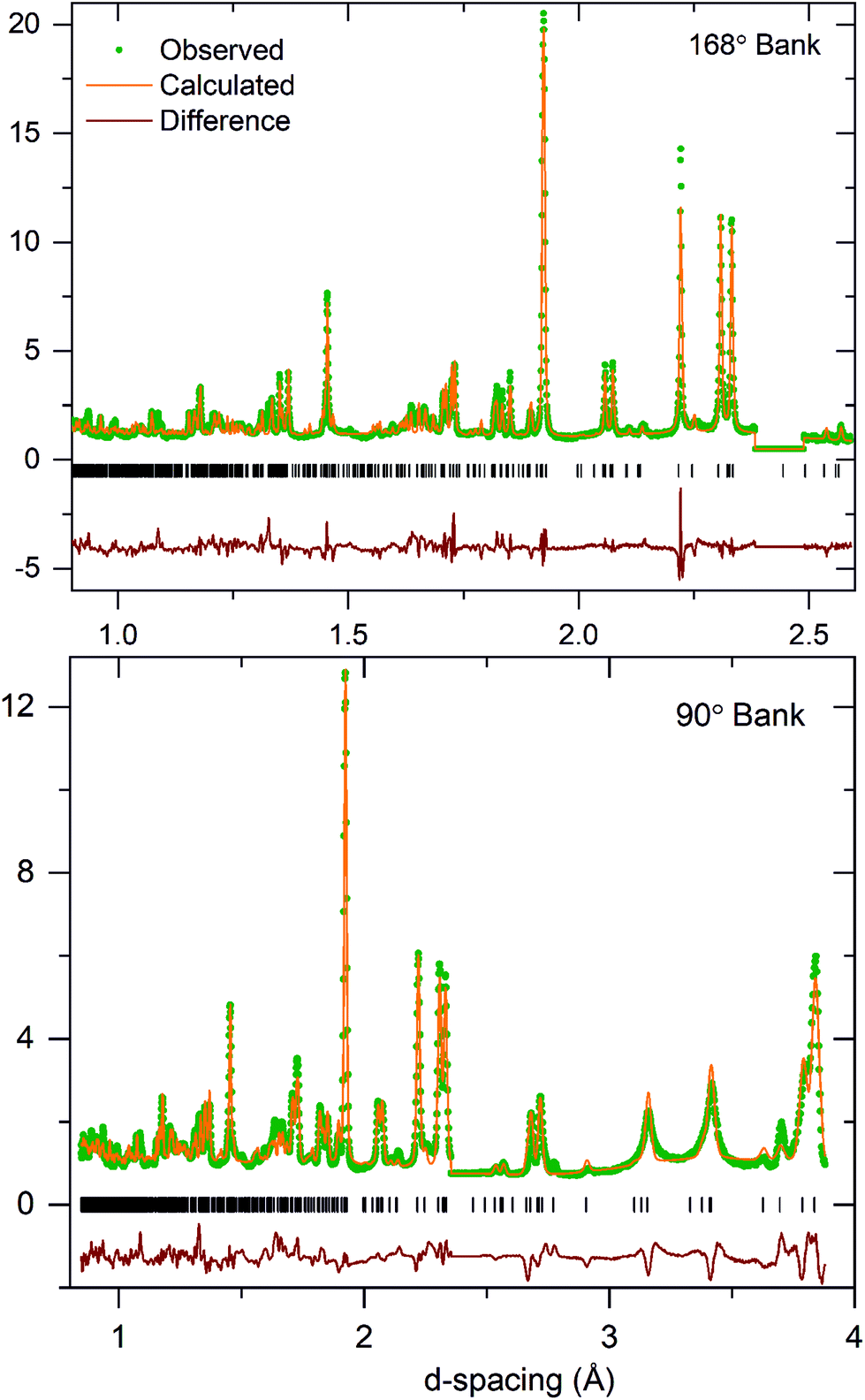 | ||
| Fig. 3 Observed, calculated and difference plots from the structural refinement of KBiNb2O7 against NPD data collected at room temperature. Excluded regions remove contributions from an unidentified impurity phase. | ||
| Atom | Site | x | y | z | Occ. | Biso (Å2) |
|---|---|---|---|---|---|---|
| KBiNb2O7 – space group A11m (#8). a = 7.6735(3) Å, b = 3.8437(2) Å, c = 22.1699(9) Å, γ = 90.806(1), V = 653.83(5) Å3, formula weight = 545.89 g mol−1, temperature: 298 K. Rp = 7.54%, wRp = 8.43%. | ||||||
| K1 | 4b | 0.003(3) | 0.967(6) | 0.1963(6) | ½ | 3.2(1) |
| K2 | 4b | 0.501(3) | 0.966(5) | 0.1965(5) | ½ | 3.2(1) |
| Bi1 | 2a | 0.0204(1) | 0.066(4) | 0 | 1 | 6.3(4) |
| Bi2 | 2a | 0.5205(1) | 0.932(4) | 0 | 1 | 6.3(4) |
| Nb1 | 4b | 0.251(1) | 0.001(1) | 0.3958(1) | 1 | 4.2(1) |
| Nb2 | 4b | 0.750(1) | 0.999(1) | 0.3957(1) | 1 | 4.2(1) |
| O1 | 2a | 0.214(1) | 0.524(4) | 0 | 1 | 5.3(2) |
| O2 | 2a | 0.713(1) | 0.475(4) | 0 | 1 | 5.3(2) |
| O3 | 4b | 0.001(1) | 0.962(5) | 0.4130(6) | 1 | 6.8(3) |
| O4 | 4b | 0.499(1) | 0.038(5) | 0.4132(5) | 1 | 6.8(3) |
| O5 | 4b | 0.275(1) | 0.009(4) | 0.3160(3) | 1 | 5.9(2) |
| O6 | 4b | 0.774(1) | 0.008(4) | 0.3159(3) | 1 | 5.9(2) |
| O7 | 4b | 0.2907(9) | 0.993(1) | 0.0889(2) | 1 | 4.3(2) |
| O8 | 4b | 0.7905(9) | 0.994(1) | 0.0888(2) | 1 | 4.3(2) |
Microstructural characterisation of KBiNb2O7
The SXRD and NPD data collected from KBiNb2O7 exhibit very strong hkl-dependent broadening, which can be seen clearly in Fig. 3 and accounts for the relatively poor fit to the data. In addition, ED patterns show extensive streaking parallel to the c* direction (Fig. 1). Together these observations suggest KBiNb2O7 exhibits some variety of stacking fault disorder. To investigate the nature of the stacking faults a series of HAADF-STEM images were collected.As noted above, the aristotype n = 2, (0, ½, z) layered perovskite structure adopted by KAB2O7 phases can be considered as a hybrid of the (0, 0, z) stacked Dion-Jacobson framework and the (½, ½, z) stacked Ruddlesden-Popper framework. HAADF-STEM images collected from KBiNb2O7 show that the BiNb2O7 perovskite sheets in KBiNb2O7 adopt an evenly spaced stacking sequence. However, close inspection shows that the stacking exhibits frequent ‘faults’ in which the (0, ½, z) stacking changes to a (½, 0, z) and vice versa, as shown in Fig. 4. This type of stacking fault corresponds to a switching of the x- and y-axes in the aristotype structure, and from the HAADF-STEM images these faults appear to be prevalent throughout the KBiNb2O7 sample measured.
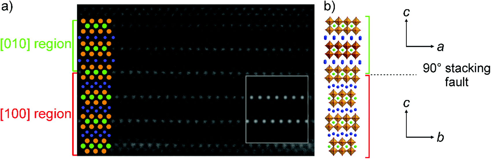 | ||
| Fig. 4 (a) HAADF-STEM image collected from KBiNb2O7. Green bracket shows stacking of BiNb2O7 sheets corresponding to [010] zone. Red bracket shows stacking corresponding to [100] zone. Superimposed spheres correspond to Bi (green), Nb (orange) and K (blue) atoms. Inset shows simulated [100] image of KBiNb2O7. (b) Representation of the 90° stacking fault in KBiNb2O7. | ||
In an attempt to quantify the frequency of this stacking fault, the structural model obtained from the NPD data was modified to introduce this ‘axis-switch’ stacking fault with a frequency defined by a variable, FF (Fault Frequency), which describes the probability that at any potassium layer there will be a change from (0, ½, z) stacking to (½, 0, z) stacking or vice versa, as described in detail in the ESI.† A series of models with different values of FF were refined against the SXRD data, whilst keeping the atomic coordinates of the model static, to find the value of FF which best fitted the data. The introduction of this fault description led to a great improvement in the fit to the data as shown in Fig. 5. As shown in Fig. 6, the best fit to the SXRD data was obtained with a value of FF = 0.09, which corresponds to a 9% chance of a stacking fault occurring between any particular pair of perovskite double sheets. This faulting probability appears to be in line with the number of faults observed in the HAADF-STEM images. Attempts to perform an analogous analysis using the NPD data were hampered by the complex double-exponential peak shape of the time-of-flight instrument.
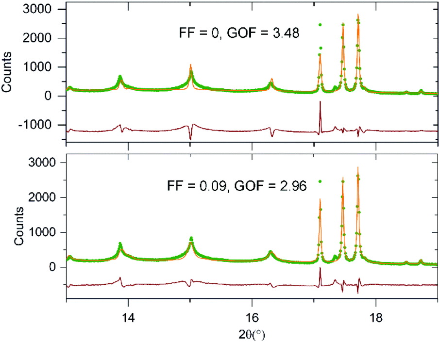 | ||
| Fig. 5 Observed calculated a difference plots from the structural refinement of KBiNb2O7 (bottom) with and (top) without 90° stacking fault description. | ||
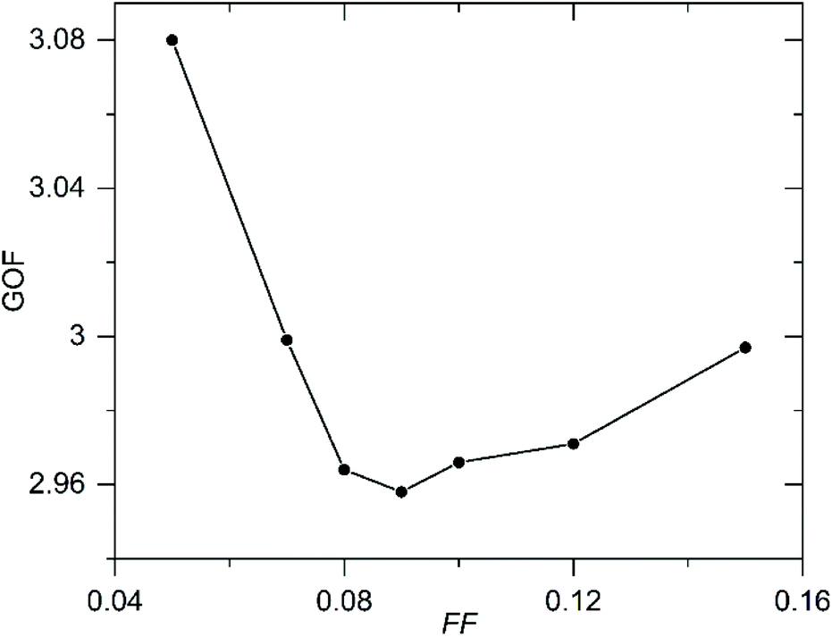 | ||
| Fig. 6 Plot of Goodness of fit (GOF) parameter against Fault Frequency (FF) determined by fitting to SXRD data. | ||
Discussion
KBiNb2O7 adopts a layered structure in which the BiNb2O7 perovskite double sheets are stacked in a (0, ½, z) manner, with the K+ cations adopting a disordered arrangement within half of the 10-coordinate sites in the interlayer region. The BiNb2O7 sheets do not adopt a cooperative tilting distortion of the NbO6 units, but are distorted by a large alternating displacement of the Bi3+ cations along the y-axis, as shown in Fig. 7. This low-symmetry, polar crystal structure differs markedly from other members of the A′BiNb2O7 (A′ = Cs, Rb, Na, Li) series. We can gain some insight into the interactions which lead to this low symmetry structure by examining how the structures of other phases in the A′BiNb2O7 series, and related A′NdNb2O7 series, evolve on changing the A′-cation. | ||
| Fig. 7 The crystal structures of KBiNb2O7 and KNdNb2O7. Purple, green, orange, grey and red spheres represent K, Bi, Nb, Nd and O respectively. | ||
As described previously,21,25,26 the stacking of the NdNb2O7 perovskite sheets and the cooperative tilting of the NbO6 units in the A′NdNb2O7 series of layered perovskite phases, can be rationalised on the basis of simultaneously satisfying the bonding requirements of both the A′ and Nd3+ cations.
It can be observed that as the size of the A′-cations declines across the A′NdNb2O7 series, so does the A′ coordination number in the resulting framework, from 8-fold (A′ = Cs, Rb) to 6-fold (A′ = K) to 4-fold (A′ = Na, Li). This change is facilitated by a change in the layer stacking type, from (0, 0, z) Dion-Jacobson stacking (A′ = Cs, Rb) to (0, ½, z) stacking (A′ = K) to (½, ½, z) Ruddlesden-Popper stacking (A′ = Na, Li). Thus, the structural evolution of the A′NdNb2O7 series can be simply rationalized on the basis of the A′-cation size.
A similar sequence of structures is adopted by some members of the A′BiNb2O7 series, with the A′ = Cs, Rb, Li phases being isostructural to their A′NdNb2O7 analogues. These isostructural relationships are perhaps a little unexpected given the preference for 6s2 Bi3+ cations to adopt asymmetric coordinations in contrast to the more symmetric environments favored by Nd3+. However, in the case of the Cs, Rb and Li phases, the large magnitude tilting distortions exhibited by the ANb2O7 sheets, which are required to simultaneously satisfy the coordination requirements of the A′ and Nd3+ cations, lower the symmetry of the A-cation sites (by way of the trilinear coupled hybrid improper mechanism)14,20 to the ..m point symmetry favored by Bi3+.28 Thus, perhaps coincidentally, Nd3+ and Bi3+ can be accommodated in the same structural frameworks, despite the contrasting features (Nd3+ small size; Bi3+ non-spherical geometry) of the two ions.
However, the differing coordination preferences of Nd3+ and Bi3+ do lead to a small difference in the structures of NaNdNb2O7 and NaBiNb2O7.25,28 Both NaANb2O7 phases adopt a (½, ½, z) stacking of the ANb2O7 layers, with Na+ cations ordered in 4-coordinate sites in the interlayer region. However, the relatively large size of Na+ means that NaNdNb2O7 adopts a small magnitude a−b0c0/b0a−c0 tilting distortion (space group P42/mnm) with the Nd3+ cation accommodated on a site of m.2m point symmetry. This site symmetry appears to be incompatible with the coordination requirements of Bi3+ as NaBiNb2O7 adopts a much larger magnitude a−a−c+/a−a−-c+ tilting distortion (space group P212121), despite Bi3+ being larger than Nd3+, which lowers the point symmetry of the Bi3+ cations to that of a general position, yielding an asymmetric bismuth coordination environment, suggesting that the change in structure occurs in response to an off-centring distortion of the Bi3+ cations.
In light of the analysis above, we can rationalise the much more significant structural differences between KNdNb2O7 and KBiNb2O7. KNdNb2O7 adopts a (0, ½, z) stacking pattern of the NdNb2O7 sheets, which themselves exhibit a cooperative a0b+c0/a0–b+c0 tilting scheme to best accommodate the K+ cations, which are ordered within half of the available 6-coordinate trigonal prismatic sites in the interlayer region of the structure as shown in Fig. 7. As noted above, KBiNb2O7 also exhibits a (0, ½, z) stacking pattern of the ANb2O7 perovskite sheets, however the remaining structural details are strongly contrasting: the K+ cations in KBiNb2O7 adopt a disordered arrangement within half of the 10-coordinate sites in the interlayer region and no cooperative tilting distortion is observed in the BiNb2O7 layers, which are instead distorted by a large alternating displacement of the Bi3+ cations, shown in Fig. 7.
Again the structural differences between the neodymium and bismuth phases can be attributed to the coordination preferences of the Nd3+ and Bi3+ cations. The a0b+c0/a0–b+c0 tilting distortion exhibited by the NdNb2O7 sheets in KNdNb2O7 results in a 222 point symmetry site for the Nd3+ cations. As noted above, such a high symmetry site appears to be incompatible with the asymmetric coordination environments adopted by Bi3+ – a statement supported by the observation that the Bi3+ sites in KBiNb2O7 have ..m point symmetry. Thus, we can attribute the change in structure on replacing Nd3+ with Bi3+ within the KANb2O7 framework to the preference for asymmetric environments exhibited by 6s2 Bi3+ cations. It is worth noting however, that in contrast to the simple change in tilting pattern on Bi3+-for-Nd3+ substitution exhibited by the NaANb2O7 framework, the potassium system undergoes a much more dramatic change in structure on the introduction of bismuth, with the K+ coordination site and the ANb2O7 layer distortion changing. The resulting structure of KBiNb2O7 has a highly distorted BiNb2O7 layer in which the NbO6 units are deformed from their expected octahedral geometry. This low symmetry arrangement suggests that it is difficult to satisfy the coordination preference of K+ and Bi3+ simultaneously in this (0, ½, z) framework, with the observed structure being the best compromise. As a consequence the inversion symmetry breaking in the non-centrosymmetric structure of KBiNb2O7 can be attributed to an SOJT-like distortion driven by the 6s2 electronic configuration of Bi3+, in contrast to KNdNb2O7 where the inversion symmetry breaking is attributed to an SOJT-like distortion driven by the Nb5+ cations.26
A further striking feature exhibited by KBiNb2O7 is the axis-switch stacking fault in which the (0, ½, z) stacking changes to (½, 0, z) stacking and vice versa. In principle, such a stacking fault should apply significant lattice strain to the materials. However, due to the lack of a cooperative NbO6 tilting distortion, the lattice parameters of KBiNb2O7 are close to being metrically tetragonal (if the x-axis doubling due to the alternating Bi displacement is ignored) so the strain associated with the faulting should be minimal. Thus we can see that the prevalent axis-switch faults can be attributed to features of the crystal structure of the material.
Conclusions
The facile cation-exchange reactions exhibited by Dion-Jacobson phases allow a wide range of metastable, layered perovskite oxide phases to be prepared. In the case of the A′BiNb2O7 series this allows the competition between alternative polar ground states stabilized by either trilinear coupling, the SOJT distortions of Nb5+O6 units, or the off-centring distortions of 6s2 Bi3+, to be studied.In the case of KBiNb2O7, we observe this phase is highly metastable, and can only be prepared through a 3-step reaction sequence. The phase produced differs significantly from the analogous Nd3+ phase, KNdNb2O7, both in the local coordination of the K+ cations and the deformation of the ANb2O7 perovskite double sheets. In addition KBiNb2O7 exhibits extensive ‘axis-switch’ stacking faults. These features combine to highlight the dominant influence of the off-centring distortions of the Bi3+ cations in this phase.
Author contributions
SM prepared the samples and performed the structural analysis, WZ and PSH collected the SHG data, MB and JH collected the microscopy data, ASG assisted with the collection of the NPD data, MAH conceived the study, wrote the manuscript and supervised the study.Conflicts of interest
There are no conflicts to declare.Acknowledgements
Experiments at the Diamond Light Source were performed as part of the Block Allocation Group award “Oxford/Warwick Solid State Chemistry BAG to probe composition-structure–property relationships in solids” (CY25166). Experiments at the ISIS pulsed neutron facility were supported by a beam time allocation from the STFC (RB 2000148). SM thanks Somerville College for an Oxford Ryniker Lloyd scholarship. ‘PSH and WZ thank the National Science Foundation (DMR-2002319) and Welch Foundation (Grant E-1457) for support.Notes and references
- M. E. Lines and A. M. Glass, Principles and Applications of Ferroelectrics and Related Materials, Oxford University Press, Oxford, 1991 Search PubMed.
- F. J. Nye, Physical Properties of Crystals, Oxford University Press, Oxford, UK, 1957 Search PubMed.
- R. E. Cohen, Nature, 1992, 358, 136–138 CrossRef CAS.
- M. Kunz and I. D. Brown, J. Solid State Chem., 1995, 115, 395–406 CrossRef CAS.
- S. K. Kang, H. Tang and T. A. Albright, J. Am. Chem. Soc., 1993, 115, 1971–1981 CrossRef CAS.
- R. G. Pearson, J. Mol. Struct.: THEOCHEM, 1983, 12, 25–34 CrossRef CAS.
- I. Lefebvre, M. Lannoo, G. Allan, A. Ibanez, J. Fourcade, J. C. Jumas and E. Beaurepaire, Phys. Rev. Lett., 1987, 59, 2471–2474 CrossRef CAS PubMed.
- I. Lefebvre, M. A. Szymanski, J. Olivier-Fourcade and J. C. Jumas, Phys. Rev. B: Condens. Matter Mater. Phys., 1998, 58, 1896–1906 CrossRef CAS.
- R. Seshadri and N. A. Hill, Chem. Mater., 2001, 13, 2892–2899 CrossRef CAS.
- M. W. Stoltzfus, P. M. Woodward, R. Seshadri, J. H. Klepeis and B. Bursten, Inorg. Chem., 2007, 46, 3839–3850 CrossRef CAS PubMed.
- G. W. Watson and S. C. Parker, J. Phys. Chem. B, 1999, 103, 1258–1262 CrossRef CAS.
- G. W. Watson, S. C. Parker and G. Kresse, Phys. Rev. B: Condens. Matter Mater. Phys., 1999, 59, 8481–8486 CrossRef CAS.
- N. A. Hill, J. Phys. Chem. B, 2000, 104, 6694–6709 CrossRef CAS.
- N. A. Benedek and C. J. Fennie, Phys. Rev. Lett., 2011, 106, 107204 CrossRef.
- N. A. Benedek, J. M. Rondinelli, H. Djani, P. Ghosez and P. Lightfoot, Dalton Trans., 2015, 44, 10543–10558 RSC.
- Y. S. Oh, X. Luo, F. T. Huang, Y. Z. Wang and S. W. Cheong, Nat. Mater., 2015, 14, 407–413 CrossRef CAS PubMed.
- S. Yoshida, H. Akamatsu, R. Tsuji, O. Hernandez, H. Padmanabhan, A. Sen Gupta, A. S. Gibbs, K. Mibu, S. Murai, J. M. Rondinelli, V. Gopalan, K. Tanaka and K. Fujita, J. Am. Chem. Soc., 2018, 140, 15690–15700 CrossRef CAS PubMed.
- S. Yoshida, K. Fujita, H. Akamatsu, O. Hernandez, A. Sen Gupta, F. G. Brown, H. Padmanabhan, A. S. Gibbs, T. Kuge, R. Tsuji, S. Murai, J. M. Rondinelli, V. Gopalan and K. Tanaka, Adv. Funct. Mater., 2018, 28, 1801856 CrossRef.
- M. F. Liu, Y. Zhang, L. F. Lin, L. Lin, S. W. Yang, X. Li, Y. Wang, S. Z. Li, Z. B. Yan, X. Z. Wang, X. G. Li, S. Dong and J. M. Liu, Appl. Phys. Lett., 2018, 113, 022902 CrossRef.
- N. A. Benedek, Inorg. Chem., 2014, 53, 3769–3777 CrossRef CAS PubMed.
- T. Zhu, T. Cohen, A. S. Gibbs, W. Zhang, P. S. Halasyamani, M. A. Hayward and N. A. Benedek, Chem. Mater., 2017, 29, 9489–9497 CrossRef CAS.
- T. Zhu, A. S. Gibbs, N. A. Benedek and M. A. Hayward, Chem. Mater., 2020, 32, 4340–4346 CrossRef CAS.
- S. Asaki, H. Akamatsu, G. Hasegawa, T. Abe, Y. Nakahira, S. Yoshida, C. Moriyoshi and K. Hayashi, Jpn. J. Appl. Phys., 2020, 59, 6 CrossRef.
- M. A. Hayward, in Comprehensive Inorganic Chemistry II, ed. J. Reedijk and K. R. Poeppelmeier, Elsevier, Oxford, 2013, vol. 2, pp. 417–453 Search PubMed.
- T. Zhu, G. Khalsa, D. M. Havas, A. S. Gibbs, W. Zhang, P. Halasyamani, N. A. Benedek and M. A. Hayward, Chem. Mater., 2018, 30, 8915–8924 CrossRef CAS.
- S. Mallick, A. S. Gibbs, W. G. Zhang, P. S. Halasyamani, N. A. Benedek and M. A. Hayward, Chem. Mater., 2020, 32, 7965–7972 CrossRef CAS.
- S. Mallick, A. D. Fortes, W. Zhang, P. S. Halasyamani and M. A. Hayward, Chem. Mater., 2021, 33, 2666–2672 CrossRef CAS.
- S. Mallick, G. Khalsa, J. Z. Kaaret, W. Zhang, M. Batuk, A. S. Gibbs, J. Hadermann, P. S. Halasyamani, N. A. Benedek and M. A. Hayward, Dalton Trans., 2021, 50, 15359 RSC.
- A. A. Coelho, Bruker AXS, Karlsruhe, Germany, 2016.
- K. M. Ok, E. O. Chi and P. S. Halasyamani, Chem. Soc. Rev., 2006, 35, 710–717 RSC.
- C. Koch, Ph. D Thesis, Arizona state University, 2002.
- M. Shimazu, Y. Tanokura and S. Tsutsumi, Jpn. J. Appl. Phys., Part 1, 1989, 28, 1877–1881 CrossRef CAS.
- J. Gopalakrishnan, V. Bhat and B. Raveau, Mater. Res. Bull., 1987, 22, 413–417 CrossRef CAS.
- M. Sato, J. Abo, T. Jin and M. Ohta, Solid State Ionics, 1992, 51, 85–89 CrossRef CAS.
- M. Sato, J. Abo, T. Jin and M. Ohta, J. Alloys Compd., 1993, 192, 81–83 CrossRef CAS.
- M. Jarvinen, J. Appl. Crystallogr., 1993, 26, 525–531 CrossRef CAS.
- N. E. Brese and M. O'Keeffee, Acta Crystallogr., Sect. B: Struct. Sci., 1991, 47, 192–197 CrossRef.
- I. D. Brown and D. Altermatt, Acta Crystallogr., Sect. B: Struct. Sci., 1985, 41, 244–247 CrossRef.
Footnote |
| † Electronic supplementary information (ESI) available: Full details of the structural and microstructural characterisation of KBiNb2O7. See DOI: 10.1039/d1dt04064b |
| This journal is © The Royal Society of Chemistry 2022 |