 Open Access Article
Highly active heterogeneous hydrogenation catalysts prepared from cobalt complexes and rice husk waste†
Felix
Unglaube
a,
Janina
Schlapp
a,
Antje
Quade
 b,
Jan
Schäfer
b and
Esteban
Mejía
 *a
*a
aLeibniz-Institut für Katalyse e. V. an der Universität Rostock, Albert-Einstein-Straße 29a, 18059 Rostock, Germany. E-mail: Esteban.Mejia@catalysis.de
bLeibniz-Institut für Plasmaforschung und Technologie e.V., Felix-Hausdorff-Str. 2, 17489 Greifswald, Germany
First published on 14th February 2022
Abstract
The utilization and valorization of agricultural waste is a key strategy for the implementation of a sustainable economy to lessen the environmental footprint of human activities on Earth. This work describes the use of rice husk (RH) from agricultural waste to prepare a highly active catalyst for the reduction of nitro compounds. RH was impregnated with various cobalt complexes bearing N-donor ligands, then pyrolyzed and the resulting composite was etched with a base to remove the silica domains. The composition and morphology of the prepared materials were investigated by IR, AAS, ICP-OES, XRD, BET, XPS and SEM technics. The material showed excellent activity and selectivity in the hydrogenation of nitro groups in aromatic and aliphatic substrates. A remarkable selectivity towards nitro groups was found in the presence of various reactive functionalities, including halogens, carbonyls, borates, and nitriles. Apart from their excellent activity and selectivity, these catalysts showed remarkable stability, allowing their easy recovery and multiple reuse without requiring re-activation.
Introduction
The sustainable development goals (SDGs), set by the UN general assembly in 2015, are referred to as “blueprints to achieve a […] more sustainable future”.1 Overall the SDGs comprise 17 objectives which are supposed to be achieved by 2030 to improve the quality of human cohabitation and sustain the Earth as habitat for humans. The utilization of agricultural waste can meet many of the SDGs by promoting sustainable agriculture (SDG 2), economic growth (SDG 8), and industrialization (SDG 9), as well as by improving production patterns (SDG 12) and reducing the emission of atmospheric pollutants (SDG 13).2,3 In this context, utilization can mean recirculation of inedible by-products of agricultural processes, including the use of bio-waste as fodder for livestock,4 or for the production of fertilizers.5,6 Utilization can also mean the use of waste in non-related economic sectors, which had caught much attention due to the broad palette of agricultural wastes and their growing amount worldwide.7 For instance, “energy-dense” wastes like manure are suitable for the production of bio fuels,8 (importantly bio gas), contributing to the energy and transport sector.9,10 Fibrous plant bio-waste like straw or bagasse can be used in the production of much needed materials like concrete,11 or filters for water purification.12 The synthesis of more advanced materials like supercapacitors,13,14 fluorescent carbon nanotubes,15 or catalysts has been part of research efforts as well, alas, to a lesser extent.The preparation of catalysts from bio-waste has proven to be a promising approach thanks to the diversity offered by bio-waste in terms of structure and composition.16 Recent examples include the use of catalysts made from banana peels,17 or oyster shells,18 for transesterification reactions, or the use of heterogeneous catalysts from rice husk (RH) for the epoxidation of limonene,19 and the reduction of nitro groups.20
Hydrogenation reactions are among the most important catalytic transformations in the chemical industry, as illustrated by the widely applied reduction of nitro compounds to amines. This reaction is a key transformation in the industrial-scale production of amines,21,22 as well as in the synthesis of active pharmaceutical ingredients like the widely used paracetamol.23 The most popular systems used to catalyze this transformation are metal-based, including Ni-RANEY®,24 NiS,25 Pd and Pt (Adams' catalyst),26 Cu–Mn–Fe or Cu@SiO2.27 These catalysts, as applied on an industrial scale, normally require harsh reaction conditions (e.g. temperatures above 200 °C), except for Pd–Pt alloys. However, high temperatures are not tolerated by most functionalized organic substrates and highly active systems suffer from insufficient selectivity towards amines. Among the few exceptions are the cobalt28 and nickel29 based systems reported independently by the groups of Zou and Beller, which display excellent activities even at room temperature.
It is possible to modify catalysts with either Fe or VO(acac)2 to improve the tolerance towards sensitive moieties like alkenes, alkynes, nitriles or carbonyl functions.30 However, most systems are able to catalyze to some extent undesired side reactions like dearomatization or reductive dehalogenation. The latter is especially problematic since relevant substrates are often bearing halogens. The use of 3d non-noble metals as catalysts has become more prevalent in the last decade since they are able to overcome selectivity issues, and being fairly abundant in the Earth crust, their mining has less environmental impact.31
During the last decade, cobalt has played an important role in the development of heterogeneous catalysts for amine synthesis via hydrogenation with 3d-metal catalysts (Scheme 1), even though the first catalytic system was published already in 1937 by Griffitts and Brown using CoS.32 Almost 80 years later, Beller et al. reported a significant improvement in the catalytic performance by supporting cobalt on a SiO2 carrier with the aid of nitrogen-donor ligands. They described the formation of coordinative interactions between cobalt species and nitrogen at the support's surface, allowing an easier activation of hydrogen.33 Based on this approach, Gascon et al. reported in 2018 a system containing Co3O4 improved by etching with HF, leaching the silica domains, which leads to higher surface area and more active sites.34
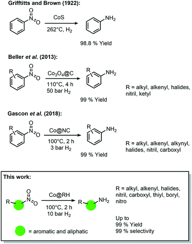 | ||
| Scheme 1 Historical development of cobalt-catalyzed synthesis of amines by hydrogenation of nitro compounds. | ||
Further improvements have been made to these Co-based catalytic systems, especially regarding the reaction conditions for the hydrogenation of nitro aromatics, as recently reported by the group of Palkovits, among others.35–37 Furthermore, a number of studies have shown the feasibility of other reduction reactions using heterogeneous cobalt catalysts, including reductive amination of carbonyl compounds,38 and the reduction of O2 to H2O2.39
The vast majority of these processes are carried out with catalysts containing highly sophisticated supporting materials which require laborious and energy-intensive synthetic procedures. Thus, the use of inexpensive bio-waste as a feedstock for the catalyst preparation (as showcased above) offers an appealing alternative, not only in economic terms, but also due to its intrinsic sustainability. However, the direct impregnation of a bio-derived feedstock with cobalt precursors for the synthesis of catalytically active materials has been rarely reported. In 2017, Beller et al. reported the preparation of a Co-based catalyst using chitosan, and its use in hydro-dehalogenation reactions,40 and hydrogenation of nitroarenes (40 bar H2 and 110 °C).41 Additionally, in 2018 Yang et al. prepared a catalyst by impregnation of bamboo with CoCl2 for hydrogenation reactions (at 110 °C and 50 bar H2).42
Rice husk (RH) is, besides rice straw, the main by-product of rice production, and is considered to be one of the most abundant agricultural waste on earth, with over 40 million tons produced in 2015 in China alone.43 Its unique structure is made up of a lignocellulose matrix decorated with silica nanoparticles (up to 20 wt% silica) and, unlike other bio-derived feedstocks like chitosan, RH does not need to be isolated or purified in a complicated manner for its utilization.
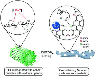
Herein, we report the use of RH as a feedstock for the preparation of cobalt-containing materials with remarkable activities as a catalyst in hydrogenation reactions. Our synthetic approach consists of a) impregnating the milled plant material (RH) with cobalt complexes bearing N-donor ligands, b) thermal treatment to generate catalytic active cobalt centers on the surface of the biogenic waste, and c) leaching of the silica domains by base etching, increasing the material's porosity and surface area, boosting the catalytic performance (Fig. 1). We demonstrate that our catalyst outperforms other “classic” and bio-derived catalysts, not only in terms of general activity under milder conditions, but also in other relevant aspects like reaction rate, recycling stability, and substrate scope including the commonly neglected aliphatic substrates.
Results and discussion
Catalyst preparation and characterization
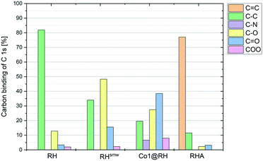
The crude, sun-dried rice husk (RH) is first chopped into small particles and ground in a ball mill to increase the accessible surface area. Subsequently, the material was washed with water and added to an ethanolic solution of an in situ prepared cobalt complex bearing nitrogen-donor ligands (Scheme 2).44–47 After removing the solvent in vacuo, the dried material was pyrolyzed at 600 °C under an inert atmosphere. Finally, the resulting ashes were etched with a base. To understand the changes underwent by the RH during this process, the surface after each step was analyzed using X-ray and microscopy techniques (see below and in the ESI†). XPS revealed that the surface of crude RH offers mainly sp3 hybridized carbon in C–C bonds with a high content of C–O bonds (Fig. 2), in accordance with the expected composition of RH being cellulose and lignocellulose.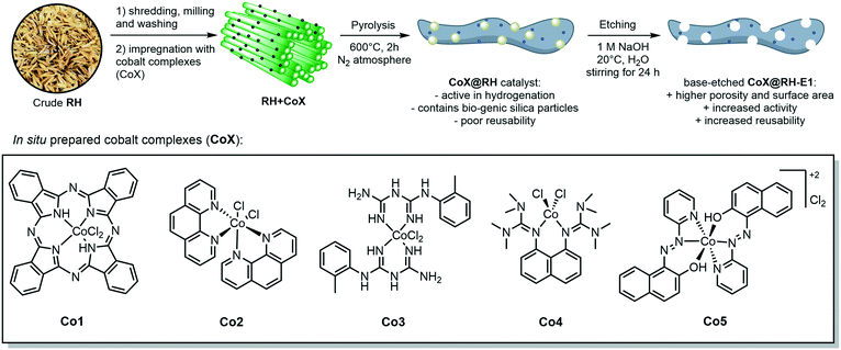 | ||
| Scheme 2 General synthetic approach for the preparation of cobalt-containing, rice-husk based catalysts for hydrogenation reactions. The annotated complexes Co1–5 were prepared in situ from cobalt(II) chloride and the corresponding ligand and neither isolated nor characterized. The depicted structure is based on previously published materials.44–47 | ||
After shredding, milling and washing (RHsmw in Fig. 2) the amount of C–C bonds on the surface is decreased from 82% to 34% and the amount of oxidized carbon (C–O and C![[double bond, length as m-dash]](https://www.rsc.org/images/entities/char_e001.gif) O in Fig. 2) increased significantly. This is most likely caused aerobic oxidation promoted by the kinetic energy supplied by the ball mill. Next, the ground RH was impregnated with cobalt complexes of five different N-containing ligands (Co1–5, Scheme 2). All the employed cobalt complexes are chelates containing multi-dentate N-donor ligands. However, they differ in the Co
O in Fig. 2) increased significantly. This is most likely caused aerobic oxidation promoted by the kinetic energy supplied by the ball mill. Next, the ground RH was impregnated with cobalt complexes of five different N-containing ligands (Co1–5, Scheme 2). All the employed cobalt complexes are chelates containing multi-dentate N-donor ligands. However, they differ in the Co![[thin space (1/6-em)]](https://www.rsc.org/images/entities/char_2009.gif) :
:![[thin space (1/6-em)]](https://www.rsc.org/images/entities/char_2009.gif) N ratio (from 1
N ratio (from 1![[thin space (1/6-em)]](https://www.rsc.org/images/entities/char_2009.gif) :
:![[thin space (1/6-em)]](https://www.rsc.org/images/entities/char_2009.gif) 4 to 1
4 to 1![[thin space (1/6-em)]](https://www.rsc.org/images/entities/char_2009.gif) :
:![[thin space (1/6-em)]](https://www.rsc.org/images/entities/char_2009.gif) 10) and can be distinguished by the “chemical nature” of the N atoms: Co1–2 are aromatic and Co3–4 are non-aromatic, while Co5 is the only complex containing oxygen. After the impregnation with Co1–5 in alcoholic solution the amount of oxygenated carbon increased and new C–N bonds appear, as expected. Not surprisingly, the major change on the surface was observed after the pyrolysis process. Nearly all of the oxygenated carbons, as well as the sp3 hybridized carbons were converted into sp2 hybridized carbons. This suggests a transformation of the hydrocarbon network (mainly composed of cellulose) to a surface mainly composed of graphene, barely decorated with oxygenated groups.
10) and can be distinguished by the “chemical nature” of the N atoms: Co1–2 are aromatic and Co3–4 are non-aromatic, while Co5 is the only complex containing oxygen. After the impregnation with Co1–5 in alcoholic solution the amount of oxygenated carbon increased and new C–N bonds appear, as expected. Not surprisingly, the major change on the surface was observed after the pyrolysis process. Nearly all of the oxygenated carbons, as well as the sp3 hybridized carbons were converted into sp2 hybridized carbons. This suggests a transformation of the hydrocarbon network (mainly composed of cellulose) to a surface mainly composed of graphene, barely decorated with oxygenated groups.
This thermal transformation of homopolysaccharides has been qualitatively described before for RH (Tulliani et al.),48 and for chitosan (Beller et al.).40
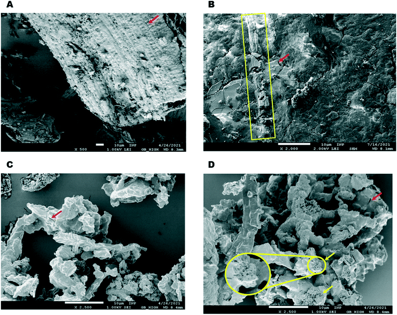
Optical and electronic microscopy studies (SEM, Fig. S1†) of crude RH have been thoroughly reported.43,49,50 The fibrous RH epidermis is characterized by the presence of small particles of silica (red arrow Fig. 3A). These features are not observable after mechanical treatment (chopping and milling) and impregnation, after which the material only shows vestiges of fibrous domains (yellow box Fig. 3B) along with smooth and crystalline bodies (red arrow in Fig. 3B), most likely corresponding to Co1–5 complexes deposited on the ground RH epidermis.
The use of HF as an etching agent for the removal of SiO2 from cobalt catalysts supported on silica/carbon composites has shown to boost its catalytic performance.51,52 However, the toxicity and safety concerns inherent in the use of HF discouraged us to use it for the treatment of our catalysts.
Instead, we decided to subject our materials to simple etching with NaOH 1 M. As expected, the silicon content in all prepared catalysts, regardless of the ligand used, is markedly reduced if the material is etched with an aqueous hydroxide base. The use of higher concentrations of NaOH further reduces the silica content but only to a limited extent; the use of 1 M NaOH decreases the Si in Co1@RH from 11.77 wt% to 3.02 wt% while the use of 2 or 4 M NaOH solution yields lower Si contents of 2.07 wt% and 1.46 wt%, respectively (Table S1†). The same trend is observed for the specific surface area of the samples: base etching of Co1@RH with 1 M NaOH increases its surface area from 323.63 m2 g−1 to 347.13 m2 g−1 (Co1@RH-E1), while the material treated with 4 M NaOH (Co1@RH-E4) displays a much higher surface area of 427.87 m2 g−1 (Co1@RH-E4, Table S2†).
Pyrolysis leads to a further significant change in morphology, resulting in irregular aggregates of smaller particles without any defined shape and brittle appearance (Fig. 3C). Interestingly, after removing the silica domains by base etching the morphology does not change greatly; the particles show a similar shape, but the etched material is clearly more porous (Fig. 3D). While a number of crevices are visible at both non-etched and the etched materials (red arrows Fig. 3C and D), a pumice-like structure is clearly present in the etched sample (yellow arrows and zoomed circled area in Fig. 3D). This change in porosity is clearly reflected in the surface measurements (Table S2†). Upon etching, the cumulative pore volume (of pores between 2 and 100 nm width) is doubled, increasing from 0.11 cm3 g−1 (for Co1@RH) to 0.27 cm3 g−1 (Co1@RH-E1). The main increase in pore volume is associated with a pore width of 1.1 to 1.4 nm and 2.7 to 3.4 nm for etching with 1 M NaOH (Fig. S44 and S46†). Interestingly, for etching with 4 M NaOH a drastic increase in pore volume is also visible from 4 to 15 nm pore width (Fig. S48†).
Importantly, the cobalt content at the catalysts' surface did not change significantly after the etching processes, as determined by ICP-OES (Table S1†). The nature of the crystalline phases in different samples was investigated by XRD (Fig. 4): in Co1@RH, a freshly etched sample without washing the sample to remove the excess base (Co1@RH-E1.fresh) and a washed sample like the one used in catalytic experiments (Co1@RH-E1.washed). The diffraction patterns showed broad reflections from 16 to 30° correlating with amorphous silica and a small peak at 26.6° from hexagonal SiO2.20 The main cobalt phases in both Co1@RH and Co1@RH-E1.washed are cubic Co and cubic CoO (σ and *, respectively). The CoO phase disappears after the etching while the main phase of cubic Co remains and three additional reflections appear: rhombohedral NaOH, which is the remaining base from the etching, hexagonal Teflon (impurity from the preparation) and rhombohedral CoO(OH) (Ψ).
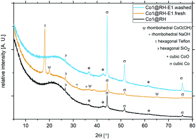 | ||
| Fig. 4 XRD patterns and different crystalline phases from cobalt catalysts at different preparation stages. Co1@RH (black), Co1@RH-E1.fresh (yellow) and Co1@RH-E1.washed (blue). | ||
The appearance of Co(III) is in line with the known facile oxidation of Co(II) at high pH values,53 resulting in the oxidation of CoO to CoO(OH) during base etching. The fact that Co(0) remains unchanged during the etching procedure suggest that a Co core covered by a CoO layer is formed. This core-layer structure has been observed in other catalytically active cobalt particles.54
To better understand the nature of nitrogen atoms at the material surface and their role in the catalytic activity, their surface was investigated using XPS (for details, see section 1 in the ESI†). The validity and usefulness of this approach has been demonstrated in previous studies.41,54,55Co1@RH shows a significantly higher share of cobalt–nitrogen (CoN) bonding (67%) compared to Co2@RH (52%) while the share of N-pyrrol and N-amm bonding (see Fig. 1 and 4) is significantly lower (Fig. 5). The etched material shows a very similar bonding distribution compared to the untreated material for both Co2@RH-E1 with CoN (51%), N-pyrrol (38%) and N-amm (11%) and for Co1@RH-E1 with CoN (66%), N-pyrrol (24%) and N-amm (9%). The use of a base of higher concentration (4 M) does not change the bonding situation. Interestingly, the nitrogen to cobalt ratio (N/Co) differs significantly from the trends found in the nitrogen bonding distribution. The ratio increases from 1.5 for Co2@RH to 3.8 for Co2@RH-E1, while drops drastically in the series Co1@RH (5.1), Co1@RH-E1 (2.7) and Co1@RH-E4 (1.3) (Fig. S13†). An inverted but analogous trend is visible in the oxygen to carbon ratio (O/C) which is higher for Co2@RH (2.6) than for Co2@RH-E1 (7.1) and increasing in the series Co1@RH (6.5), Co1@RH-E1 (9.5), and Co1@RH-E4 (15.3) (Fig. S14†).
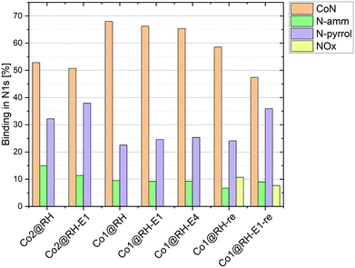 | ||
| Fig. 5 Nitrogen bonding measured by XPS in different catalysts at different stages; “re” stands for “recycled”. | ||
Catalytic hydrogenation of nitro compounds
The hydrogenation of nitrobenzene to aniline was chosen as a model reaction to test and optimize the catalytic activity of all prepared materials (Table 1). The use of catalysts prepared in the absence of N-donor ligands (Co@RH) leads to lower catalytic activity compared to those catalysts made using cobalt complexes of N-donor ligands Co1–5 (Table 2). Co1@RH showed the best performance with 39% yield of aniline, followed by Co2@RH (22%), Co3@RH (16%), Co4@RH (12%) and Co5@RH (1.2%). It is noteworthy that the best results were obtained with catalysts prepared from complexes containing aromatic N-heterocycles without oxygen (Co1–3). The significant reduction of yield using Co5, the only oxygen-bearing ligand, is in marked contrast with recent data reported by Beller et al. who used cobalt–salen complexes to generate catalytically active Co nanoparticles.56 Moreover, cobalt phthalocyanines (like in Co1) are known to form active reduction catalysts after pyrolysis.57–60 Thus, the high activity of Co1@RH is in line with this precedent.| Catalyst | c(NaOH)a [mol l−1] | Yield of anilineb [%] |
|---|---|---|
| Reaction conditions: 10 bar H2, 100 °C, 16 h, in acetonitrile (1 ml) and 20 mg catalyst.a Base concentration used for etching.b Yield was determined by GC using n-octane as an internal standard. | ||
| Co@RH | — | 5 |
| Co1@RH | — | 39 |
| Co1@RH-E1 | 1 | 83 |
| Co1@RH-E2 | 2 | 83 |
| Co1@RH-E4 | 4 | 85 |
| Co2@RH | — | 22 |
| Co2@RH-E1 | 1 | 38 |
| Co3@RH | — | 16 |
| Co3@RH-E1 | 1 | 29 |
| Co4@RH | — | 12 |
| Co4@RH-E1 | 1 | 16 |
| Co5@RH | — | 1.3 |
| Co5@RH-E1 | 1 | 1.3 |
| Catalyst | T [°C] | pH2 [bar] | Solventa | Base additive | Yield of anilineb [%] |
|---|---|---|---|---|---|
| a i-PrOH/H2O have been used in an equal volume ratio. b Yield of aniline was determined by GC using n-octane as an internal standard. | |||||
| Co1@RH-E1 | 120 | 10 | Heptane | — | 56 |
| Co1@RH-E1 | 120 | 10 | Ethanol | — | 65 |
| Co1@RH-E1 | 120 | 10 | H2O | — | 86 |
| Co1@RH-E1 | 120 | 10 | Ethanol/H2O | — | 97 |
| Co1@RH-E1 | 120 | 10 | i-PrOH/H2O | — | 99 |
| Co1@RH | 120 | 10 | i-PrOH/H2O | — | 89 |
| Co1@RH-E1 | 120 | 5 | i-PrOH/H2O | — | 43 |
| Co1@RH | 120 | 5 | i-PrOH/H2O | — | 19 |
| Co1@RH-E1 | 90 | 10 | i-PrOH/H2O | — | 85 |
| Co1@RH-E1 | 100 | 10 | i-PrOH/H2O | — | 92 |
| Co1@RH | 100 | 10 | i-PrOH/H2O | — | 27 |
| Co1@RH-E1 | 110 | 10 | i-PrOH/H2O | — | 95 |
| Co1@RH | 110 | 10 | i-PrOH/H2O | — | 43 |
| Co1@RH-E1 | 130 | 10 | i-PrOH/H2O | — | 96 |
| Co1@RH-E1 | 120 | 10 | i-PrOH/H2O | Pyridine | 87 |
| Co1@RH | 120 | 10 | i-PrOH/H2O | Pyridine | 84 |
| Co1@RH-E1 | 120 | 10 | i-PrOH/H2O | NaOH | 89 |
| Co1@RH-E1 | 120 | 10 | i-PrOH/H2O | NEt3 | 83 |
| Co1@RH-E1 | 120 | 10 | i-PrOH/H2O | NaCO3 | 71 |
| Co1@RH | 120 | 10 | i-PrOH/H2O | NaCO3 | 50 |
The surface area is another parameter which must be considered when comparing the catalytic activity of the prepared materials (Table S2†). While the micropore and BET surface area are within a similar range for all catalysts, there are differences in the cumulative pore volume. Therefore, Co1@RH-E1, the most active catalyst, shows the highest macropore volume (0.27 cm3 g−1), while all other catalysts have similar macropore volumes. Additionally, Co1@RH-E4, which has the highest surface area (428 m2 g−1) but a similar macropore volume (0.25 cm3 g−1), shows no significant increase in catalytic activity.
A screening of the pyrolysis temperature for the preparation of Co1@RH revealed that the material prepared at 600 °C was the most active in nitrobenzene conversion. Significantly lower yields were achieved using the catalyst prepared at 500, 700, 800 or 900 °C, respectively (Fig. S58†).
When RH is used as a feedstock for the synthesis of silica, silicon, carbon or their composites, it is common practice to wash the raw plant material with an aqueous acid to remove eventual traces of heavy metals.61 In our case, we observed that an acidic washing of the RH prior to impregnation does not improve the catalytic activity. Thus, skipping the acidic pre-treatment altogether, we could avoid the generation of approximately 30 liters of acidic wastewater per kg of catalyst produced.
The reaction conditions have been optimized for the nitrobenzene conversion to aniline using Co1@RH and Co1@RH-E1 to determine the differences of both catalysts resulting from base etching. The screening revealed that the etched catalyst outperformed the untreated material in every case. For instance, assessment of the optimal catalyst loading showed that Co1@RH-E1 achieved quantitative yields of aniline with only 20 mg of catalyst (corresponding to 1.8 mol% cobalt) while 41 mg of Co1@RH (corresponding to 4 mol% cobalt) was required (Fig. S60†). A similar trend was observed in the pressure screening, with full yield at 10 bar H2 using Co1@RH-E1 and 20 bar H2 pressure using Co1@RH. The temperature screening showed a maximum performance at 120 °C, while at 130 °C the yield decreased, most likely caused by the lower hydrogen solubility at higher temperatures (Fig. S63†). The use of polar protic solvents has shown to give the highest yields, a water and isopropanol 1![[thin space (1/6-em)]](https://www.rsc.org/images/entities/char_2009.gif) :
:![[thin space (1/6-em)]](https://www.rsc.org/images/entities/char_2009.gif) 1 mixture being the one with the best results (Fig. S59†).62,63
1 mixture being the one with the best results (Fig. S59†).62,63
Since previous studies have shown that the addition of bases has a positive effect on the hydrogenation of nitro groups (by promoting the deprotonation of azoxy intermediates),64 we performed a small base screening in our model reaction (Fig. S62†). Surprisingly, the addition of bases to our system (whether organic or inorganic) appears to be detrimental (Table 2), a phenomenon which we observed in other RH-based systems before.20
When comparing the catalytic performance of the prepared materials with literature reports, they have shown to be better than, or at least comparable with most reported catalysts.64,65 Some superior systems include those developed by the teams of Palkovits and Beller, operating at 40 °C,36 and those by Zou and co-workers, which are very active even at room temperature.28
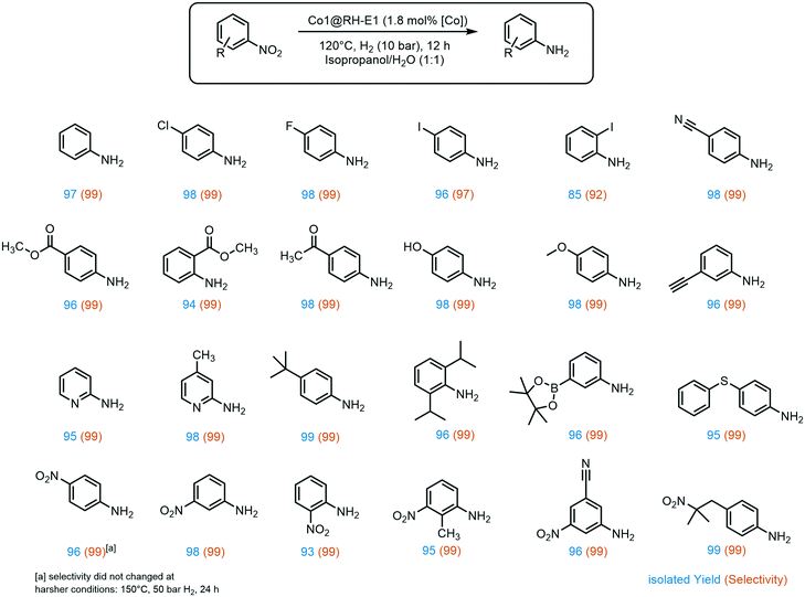
A broad substrate screening was done to determine the extent and limits of the prepared hydrogenation catalyst. A series of aromatic nitro compounds were tested, obtaining in almost all cases quantitative yields and 99% selectivity towards the reduction of the nitro group (Fig. 6). The catalysis has shown to be highly chemoselective, reducing only the nitro groups even in the presence of other potentially reactive groups, including nitriles, ketones, aldehydes and alkynes. The inertness of our system towards nitrile groups came as a surprise, since very similar cobalt based systems are known to be excellent catalyst for the hydrogenation of these functionalities.54 Importantly, halogen-containing substrates are also well tolerated; i.e. the high yield of 4-iodoaniline (96%) suggests that dehalogenation of the nitro-precursor hardly takes place, which is a well-known side reaction in the hydrogenation of iodine-containing compounds with highly active catalysts.40,66 Moreover, sterically demanding groups in the ortho position to the nitro group lead to slightly decreased yields, as observed for methyl-4-aminobenzoate (96% yield) versus methyl-2-aminobenzoate (94% yield). Additionally, the lower yield of 85% of 2-iodoaniline is an indicator for the negative impact of good leaving groups in the ortho position on the reaction while aliphatic groups like isopropyl do not show a negative influence. Furthermore, the catalyst showed good tolerance to a variety of functional groups at the meta position to the nitro group, especially prone towards side reactions.67 These include boron groups, which are highly relevant for coupling reactions.68–70 Additionally, the catalyst is not poisoned by sulfur atoms in the substrate, which is a common problem in heterogeneous hydrogenation catalysis.71,72
A very interesting selectivity feature was observed during the substrate screening: if the molecule offered more than one nitro group, only one nitro moiety was reduced in all cases. To the best of our knowledge, the system presented here is the first cobalt-based catalytic system to display this type of selectivity. There are only a few examples of heterogeneous catalysts for selective hydrogenation of only one nitro group when two are present in the same molecule, and a number of them use NaBH4 as a reducing agent.73–76 There are only a few examples where hydrogen is used instead, and all of them rely on rare and expensive metals like ruthenium,77 platinum–palladium alloy,78 or gold.79,80 Recently, our group developed a silver-based system also using rice husk ashes as a support, with the same selectivity.20 Interestingly, all these systems, except the silver-based, exhibit apparent activity for kinetic product control. This does not seem to be the case for the RH based systems as no diamino species could be detected even with prolonged reaction time, higher pressure, and increased reaction temperature. However, to provide an explanation for this behavior, a comprehensive mechanistic investigation must be undertaken.
The above-mentioned trend of giving slightly lower yields when another substituent is present in the ortho position to the nitro groups also holds for dinitro compounds, giving the lowest 1,2-dinitrobenzene yield among all three isomers (93%). Interestingly, aromatic nitro groups were preferably hydrogenated over aliphatic nitro groups, as demonstrated by the synthesis of 4-(2-methyl-2-nitropropyl)aniline.
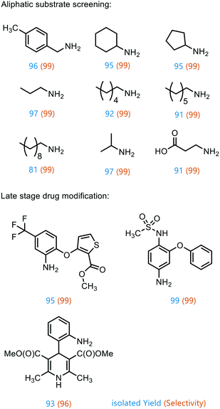
To prove the versatility of Co1@RH-E1 as a hydrogenation catalyst, a range of aliphatic substrates was investigated (Fig. 7). It was shown that both small and polar as well as long-chain lipophilic substrates could be hydrogenated in almost complete yields. However, with increasing chain length, the yield decreased proportionally. The catalyst also showed good performance in the conversion of cyclic aliphatic nitro compounds into the corresponding amines, indicating that it is not a problem to hydrogenate the oxime-nitroso intermediate (stabilized by mesomerism), as previously observed.20
Furthermore, the applicability of the synthesized catalyst in late-stage drug modification was demonstrated (Fig. 7). Nimesulide,81 which is used as a non-steroidal anti-inflammatory drug and selective cyclooxygenase-2 inhibitor,82 was converted into the corresponding amine without reducing the sensitive sulfone moiety in excellent yield. Moreover, the selective synthesis of 4-(2-methyl-2-nitropropyl)aniline was achieved in good yield (93%) and with excellent selectivity (96%), regardless of the redox sensitive dihydropyridine core. This has so far only been described using stoichiometric amounts of Na2S in moderate yields of 70%.83
Recycling experiments
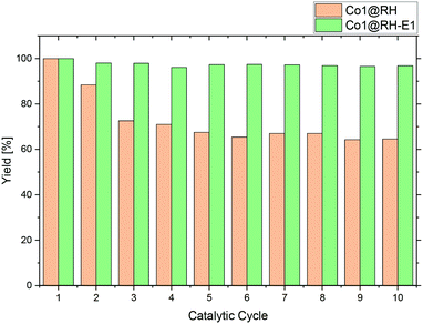
A major advantage of heterogeneous catalytic systems over their homogeneous counterparts is the possibility of easy recycling. After reaction, the catalyst can be removed by simple filtration or centrifugation, or by action of a magnetic field if the material has a magnetic moment,84 which is the case with the material presented here. Thus, the catalyst could be easily recovered from the reaction solution with a magnet.Recycling experiments with the untreated (before etching) catalyst Co1@RH showed that a yield drops from nearly 100% down to 70% after five runs and stabilized at that level. However, the recycling stability of the base-etched catalyst Co1@RH-E1 turned out to be superior to Co1@RH, as no decrease in activity was observed over 10 runs (Fig. 8). The better recycling stability of Co1@RH-E1 was also indicated by the fact that the reaction solution after the separation of the catalyst was clear after every cycle, whereas the reaction solution obtained when Co1@RH was used was cloudy after a couple of cycles, suggesting a mechanical deterioration of the material. This is indeed visible in SEM measurements. The particle morphology changes drastically during the recycling process for both un-etched and etched materials (Fig. S9†). However, the type of change is very different; while particles of Co1@RH are fractured into smaller ones, around 1 to 10 μm, the particle size of Co1@RH-E1 after recycling is considerably bigger, between 10 and 20 μm. This suggests that the etched material has an enhanced mechanical stability, which contributes significantly to the higher recycling stability.
Perhaps correlated to the lower mechanical stability is the drastic increase of the oxygen–carbon ratio during the recycling of Co1@RH, which is higher than that of Co1@RH-E1, (Fig. S14†). Additionally, XPS revealed that the amount of CoN bonding is just slightly decreased from 67% to 58% in the un-etched material, compared to a stronger decrease of 66% to 47% in the etched catalyst. This suggests that the oxidation stability of the support is critical to the recycling stability of the material, while the amount of cobalt nitrogen bonding plays a lesser role. The general oxidation stability of the nitrogen species at the surface seems to be also of relevance since the amount of NOx bonding is slightly higher in the un-etched material with 11% compared to 7% in the etched material.
Kinetic studies and reaction mechanism
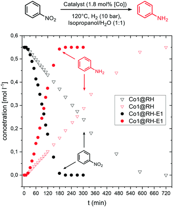
Kinetic investigations on the hydrogenation of nitrobenzene revealed a zeroth order dependence with respect to the substrate at high concentrations for both Co1@RH and Co1@RH-E1. Previous kinetic studies interpreted similar results by applying the Langmuir–Hinshelwood model,85–87 identifying the reaction of hydrogen and nitrobenzene at the catalyst surface as the rate determining step, and therefore the adsorption of all reaction partners on the catalyst surface as well.88 For Co1@RH-E1 and Co1@RH, initial reaction rates (r) of 1938 and 290 [molaniline per molcobalt h], respectively, were calculated. This demonstrates the superiority of the base-etched catalyst over the untreated material. The initial rate calculated for Co1@RH is lower than for a Pd–Al2O3 based system (473 [molaniline per molpalladium h]) reported by Shi et al.,85 which is in turn outperformed by Co1@RH-E1. An activation energy of 28.0 ± 1.1 [kJ mol−1] for the reaction using the etched material was calculated based on the Arrhenius equation (Fig. S74†). This energy is lower than the 44.8 [kJ mol−1] determined for the highly active etched cobalt-based system by Zhou et al.52 and the 67.2 [kJ mol−1] observed by Gomez et al. for an Au/ZrO2 catalyst.89Comparing the concentration–time profile of Co1@RH and Co1@RH-E1, it is clearly visible that the reaction is significantly faster with the etched catalyst: the reaction is completed after 10 h using Co1@RH and after 3 h using Co1@RH-E1 (Fig. 9). It is noted that all reactions show an induction time within the first ten minutes. This phenomenon is most likely caused by insufficient or inhomogeneous heating of the reaction mixture while placing the autoclave in the preheated aluminum block.
A major challenge in understanding heterogeneous catalysts is to achieve an accurate description of the catalytic active center. XPS has proven to be a well-suited tool for this purpose in previous studies. The apparent correlation between higher CoN bonding fractions and higher catalytic activities (with Co1@RH-E1 compared to the less active Co2@RH-E1) as shown in Fig. 5 is consistent with previous studies. They propose a coordination interaction between pyridinic nitrogen atoms at the surface with adsorbed hydrogen, leading to easier activation/cleavage by the cobalt centers.55 However, as mentioned before, the nature of CoN bonding is not the only measure to describe the activity of the present system, since the CoN bonding fraction in the more active material is approx. 10% lower after several recycling runs. Nevertheless, it is generally accepted that the Co–N–C interaction is key to achieve highly active and chemoselective heterogeneous Co-catalysts on a carbon matrix.35,90 The data obtained in this study do not suggest otherwise. However, we see an increased fraction of N-pyrrol bonding at the expense of CoN binding, indicating a change in the cobalt–nitrogen interplay without negative effects on the catalytic activity. Additionally, the amount of cobalt in the bulk material compared to the amount of cobalt on the surface must be considered. It is noted that the most active catalyst, Co1@RH-E1, has the lowest cobalt content (5.5 m%) but with 2.6 mol% on the surface, almost twice as much compared with Co2@RH-E1. This indicates that the distribution of cobalt on the carbon matrix is highly relevant for the catalytic activity as well.
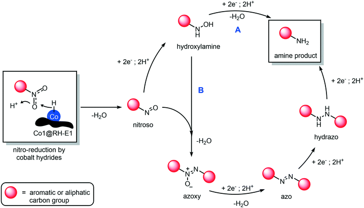
The mechanism of hydrogenation of nitro compounds over heterogeneous cobalt catalysts is well known,64 as has been shown to occur through at least two competitive pathways: the “direct” double hydrogenation of the nitro group via hydroxylamine (Fig. 10, path A) or through a condensation reaction between the nitroso and hydroxylamine intermediates, to yield a hydrazo compound which is rapidly reduced to yield the final amine product (Fig. 10, path B). In our system, whilst not much can be said about the role of path A, we could prove the occurrence of path B, as the intermediacy of azoxy and azo compounds was observed, as they quickly accumulate and disappear in the reaction mixture (Fig. S75†). In any case, independent from the preferred reaction pathway, the hydrogenation of aromatic and aliphatic nitro compounds proceeded with exquisite yields and selectivity in our hands, as no side products in relevant amounts were detected.
Experimental
Catalyst preparation
The rice husk was dried under the sun at the harvesting sites in Vietnam by local farmers (see the ESI† for further details). All samples were shredded with a SM 200 (1000 rpm, 2 mm sieve sizes) cutting mill and milled for 3 h in a ball mill PM 200 in steel cups using steel balls at 400 rpm.Characterization methods
A detailed description of the used analytical methods for catalyst characterization and characterization of the products from the catalytic experiments as well as from the kinetic experiments is given in the ESI† including NMR, GC, GC-MS, IR, ICP-OES, EA (for C, H, N and S), BET, XRD, XPS and SEM imaging.Catalytic experiments
Recycling and hot filtration experiment
200 mg of Co1@RH-E1, nitrobenzene (816 μl, 8 mmol), isopropanol (7 mmol, 0.5 ml) and water (28 mmol, 0.5 ml) were used following a general procedure. For the hot filtration experiment 50 mg of catalyst, nitrobenzene (204 μl, 2 mmol), isopropanol (14 mmol, 1 ml) and water (56 mmol, 1 ml) were added and used as described in the general procedure for catalytic experiments. After 2 h, the autoclave was abruptly cooled down to 70 °C and the pressure was lowered. The reaction solution was filtered through a filter and a Celite plug, and a sample was taken for GC analysis. The filtered reaction mixture (without a catalyst) was transferred in a fresh vial and the reaction continued under the conditions described above.Kinetic experiments
All kinetic experiments were conducted in a 200 ml autoclave using nitrobenzene (12.3 ml, 120 mmol), isopropanol (10.5 mol, 75 ml) and water (42 mol, 75 ml), equipped with a Teflon-coated magnetic stirrer and a riser pipe of 0.2 mm diameter for taking samples. The sealed autoclave was flushed three times with hydrogen at 10 bar and placed in the preheated aluminium block. The riser pipe was flushed each time before taking samples and the pressure was adjusted if necessary. All experiments have been measured in triplicate.Conclusions
Herein we present a novel heterogeneous cobalt-based catalyst for the highly chemoselective hydrogenation of nitro compounds, prepared from agricultural biowaste. The catalyst was synthesized by impregnating waste rice husk with cobalt complexes containing nitrogen ligands. The obtained material is mainly composed of carbon, silica and cobalt–nitrogen centers, which were identified by XPS. The catalytic performance of the material is enhanced by base etching, which removed a significant amount of the silica domains, resulting in a larger surface area, increased activity, and excellent recycling stability. Furthermore, the catalyst shows a broad substrate scope, being active towards both aliphatic and aromatic substrates, yielding the corresponding amines even in the presence of easily reducible groups, including additional nitro groups in the same molecule (thus reducing only one), which is an outstanding feature compared to other highly active hydrogenation catalysts.We foresee that the implementation of this methodology within a bio-refinery concept in rice-farming communities is feasible within a reachable timescale (which is the overall goal of the consortium this project belongs to). The success of the said bio-refinery can be used to effectively meet some of the most relevant sustainable development goals (SDGs) of agricultural societies, addressing economic growth, innovation, industrialization, and improvement of production and recycling patterns, while reducing the nefarious footprint of human activities on the planet.
Author contributions
F. Unglaube conceptualised the work, planned the experiments, conducted most of them, and co-wrote the manuscript. J. Schlapp conducted and evaluated various experiments. A. Quade conducted and evaluated the XPS measurements. J. Schäfer conducted and evaluated the SEM measurements. E. Mejía conceptualised and planned the research, supervised the work, and co-wrote the manuscript. All authors revised and authorized the final version of the manuscript.Conflicts of interest
There are no conflicts to declare.Acknowledgements
We would like to thank all the Vietnamese farmers and local authorities at the sample collection sites for their help and hospitality. We would like to acknowledge Dr. Abel Salazar for helpful discussions and inspiration. Also, thanks to Dr. Hendrik Lund and Kathleen Schubert, as well as Reinhard Eckelt for performing the XRD and BET-surface measurements (respectively), and for their helpful comments and discussions. This work has been supported by the RoHan Project funded by the German Academic Exchange Service (DAAD, No. 57315854) and the Federal Ministry for Economic Cooperation and Development (BMZ) inside the framework “SDG Bilateral Graduate school programme”. Furthermore, we would like to acknowledge the funding for the SUVALIG project from the German Federal Ministry of Education and Research (BMBF, 031B0707B).Notes and references
- U. N. GeneralAssembly, Resolution adopted by the General Assembly on 6 July 2017, A/RES/71/313, 2017 Search PubMed.
- B. Lomborg, Global Policy, 2016, 7, 109–118 CrossRef.
- V. Masson-Delmotte, P. Zhai, A. Pirani, S. L. Connors, C. Péan, S. Berger, N. Caud, Y. Chen, L. M. I. G. Goldfarb, M. Huang, K. Leitzell, E. Lonnoy, J. B. R. Matthews, T. K. Maycock, T. Waterfield, R. Y. O. Yelekçi and B. Zhou, IPCC, Climate Change 2021: The Physical Science Basis. Contribution of Working Group I to the Sixth Assessment Report of the Intergovernmental Panel on Climate Change, Cambridge University Press, 2021 Search PubMed.
- H. P. Makkar, Anim. Prod. Sci., 2016, 56, 519–534 CrossRef CAS.
- H.-y. Wang, L. Shen, L.-m. Zhai, J.-z. Zhang, T.-z. Ren, B.-q. Fan and H.-b. Liu, J. Integr. Agric., 2015, 14, 158–167 CrossRef CAS.
- Z. Mengqi, A. Shi, M. Ajmal, L. Ye and M. Awais, Biomass Convers. Biorefin., 2021, 1–24 Search PubMed.
- K. Foo and B. Hameed, Renewable Sustainable Energy Rev., 2010, 14, 1445–1452 CrossRef CAS.
- S. Jung, N. P. Shetti, K. R. Reddy, M. N. Nadagouda, Y.-K. Park, T. M. Aminabhavi and E. E. Kwon, Energy Convers. Manage., 2021, 236, 114038 CrossRef CAS.
- D. Cheng, Y. Liu, H. H. Ngo, W. Guo, S. W. Chang, D. D. Nguyen, S. Zhang, G. Luo and Y. Liu, Bioresour. Technol., 2020, 313, 123683 CrossRef CAS PubMed.
- K. Obileke, H. Onyeaka and N. Nwokolo, Int. J. Energy Res., 2021, 45, 3761–3779 CrossRef CAS.
- J. He, S. Kawasaki and V. Achal, Sustainability, 2020, 12, 6971 CrossRef CAS.
- K. Foo and B. Hameed, Adv. Colloid Interface Sci., 2009, 152, 39–47 CrossRef CAS PubMed.
- C. d. M. S. Rios, V. Simone, L. Simonin, S. Martinet and C. Dupont, Biomass Bioenergy, 2018, 117, 32–37 CrossRef.
- V. S. Bhat, P. Kanagavalli, G. Sriram, N. S. John, M. Veerapandian, M. Kurkuri and G. Hegde, J. Energy Storage, 2020, 32, 101829 CrossRef.
- V. Singh, S. Chatterjee, M. Palecha, P. Sen, B. Ateeq and V. Verma, Carbon Lett., 2021, 31, 117–123 CrossRef.
- R. Bharati and S. Suresh, in Biofuels and bioenergy (BICE2016), Springer, 2017, pp. 25–32 Search PubMed.
- M. Fan, H. Wu, M. Shi, P. Zhang and P. Jiang, Green Energy Environ., 2019, 4, 322–327 CrossRef.
- N. Nakatani, H. Takamori, K. Takeda and H. Sakugawa, Bioresour. Technol., 2009, 100, 1510–1513 CrossRef CAS PubMed.
- H. M. Salvi and G. D. Yadav, ACS Omega, 2020, 5, 22940–22950 CrossRef CAS PubMed.
- F. Unglaube, C. R. Kreyenschulte and E. Mejía, ChemCatChem, 2021, 13, 2583–2591 CrossRef CAS.
- P. F. Vogt and J. J. Gerulis, in Ullmann's Encyclopedia of Industrial Chemistry, Wiley-VCH Verlag GmbH & Co. KGaA, 2000, p. 699, DOI:10.1002/14356007.a02_037.
- P. Roose, K. Eller, E. Henkes, R. Rossbacher and H. Höke, in Ullmann's Encyclopedia of Industrial Chemistry, Wiley-VCH Verlag GmbH & Co. KGaA, 2015, pp. 1–55, DOI:10.1002/14356007.a02_001.pub2.
- C. G. S. Gopinathan, J. Kuruvilla, S. A. Pardhy and P. Ratnasamy, US Pat., US5856575A, 1997 Search PubMed.
- D.-Q. Xu, Z.-Y. Hu, W.-W. Li, S.-P. Luo and Z.-Y. Xu, J. Mol. Catal. A: Chem., 2005, 235, 137–142 CrossRef CAS.
- P. Baumeister, H. Blaser and W. Scherrer, in Studies in Surface Science and Catalysis, Elsevier, 1991, vol. 59, pp. 321–328 Search PubMed.
- G. Wu, M. Huang, M. Richards, M. Poirier, X. Wen and R. W. Draper, Synthesis, 2003, 2003, 1657–1660 CrossRef.
- H.-J. Arpe, Industrial Organic Chemistry, Wiley-VCH, Weinheim, 2010 Search PubMed.
- R. Gao, L. Pan, Z. Li, X. Zhang, L. Wang and J.-J. Zou, Chin. J. Catal., 2018, 39, 664–672 CrossRef CAS.
- P. Ryabchuk, G. Agostini, M.-M. Pohl, H. Lund, A. Agapova, H. Junge, K. Junge and M. Beller, Sci. Adv., 2018, 4, eaat0761 CrossRef PubMed.
- H.-U. Blaser, H. Steiner and M. Studer, ChemCatChem, 2009, 1, 210–221 CrossRef CAS.
- L. R. Pokhrel and B. Dubey, Crit. Rev. Environ. Sci. Technol., 2013, 43, 2352–2388 CrossRef.
- F. Griffitts and O. Brown, J. Phys. Chem., 1937, 41, 477–484 CrossRef CAS.
- F. A. Westerhaus, R. V. Jagadeesh, G. Wienhöfer, M.-M. Pohl, J. Radnik, A.-E. Surkus, J. Rabeah, K. Junge, H. Junge, M. Nielsen, A. Brückner and M. Beller, Nat. Chem., 2013, 5, 537–543 CrossRef CAS PubMed.
- X. Sun, A. I. Olivos-Suarez, D. Osadchii, M. J. V. Romero, F. Kapteijn and J. Gascon, J. Catal., 2018, 357, 20–28 CrossRef.
- Y. Dai, C. Jiang, M. Xu, B. Bian, D. Lu and Y. Yang, Appl. Catal., A, 2019, 580, 158–166 CrossRef CAS.
- W. Li, J. Artz, C. Broicher, K. Junge, H. Hartmann, A. Besmehn, R. Palkovits and M. Beller, Catal. Sci. Technol., 2019, 9, 157–162 RSC.
- M. Elfinger, T. Schönauer, S. Thomä, R. Stäglich, M. Drechsler, M. Zobel, J. Senker and R. Kempe, ChemSusChem, 2021, 14, 2360–2366 CrossRef CAS PubMed.
- Z. Yuan, B. Liu, P. Zhou, Z. Zhang and Q. Chi, J. Catal., 2019, 370, 347–356 CrossRef CAS.
- J. Wu, A. Mehmood, G. Zhang, S. Wu, G. Ali and A. Kucernak, ACS Catal., 2021, 5035–5046, DOI:10.1021/acscatal.0c05701.
- B. Sahoo, A. E. Surkus, M. M. Pohl, J. Radnik, M. Schneider, S. Bachmann, M. Scalone, K. Junge and M. Beller, Am. Ethnol., 2017, 129, 11394–11399 Search PubMed.
- B. Sahoo, D. Formenti, C. Topf, S. Bachmann, M. Scalone, K. Junge and M. Beller, ChemSusChem, 2017, 10, 3035–3039 CrossRef CAS PubMed.
- T. Song, P. Ren, Y. Duan, Z. Wang, X. Chen and Y. Yang, Green Chem., 2018, 20, 4629–4637 RSC.
- Y. Zou and T. Yang, in Rice Bran and Rice Bran Oil, Elsevier, 2019, pp. 207–246 Search PubMed.
- K. Mochizuki and M. Fujimoto, Bull. Chem. Soc. Jpn., 1985, 58, 1520–1523 CrossRef CAS.
- S. M. Soliman, M. A. Abu-Youssef, J. Albering and A. El-Faham, J. Chem. Sci., 2015, 127, 2137–2149 CrossRef CAS.
- P. Ray, Chem. Rev., 1961, 61, 313–359 CrossRef CAS.
- M. A. Al-Omair, Arabian J. Chem., 2019, 12, 1061–1069 CrossRef CAS.
- D. Ziegler, F. Boschetto, E. Marin, P. Palmero, G. Pezzotti and J.-M. Tulliani, Sens. Actuators, B, 2021, 328, 129049 CrossRef CAS.
- V. Malhotra, Concr. Int., 1993, 15, 23–28 CAS.
- T.-H. Liou, Mater. Sci. Eng., A, 2004, 364, 313–323 CrossRef.
- F. Zhang, C. Zhao, S. Chen, H. Li, H. Yang and X.-M. Zhang, J. Catal., 2017, 348, 212–222 CrossRef CAS.
- P. Zhou, L. Jiang, F. Wang, K. Deng, K. Lv and Z. Zhang, Sci. Adv., 2017, 3, e1601945 CrossRef PubMed.
- D. Nicholls, The chemistry of iron, cobalt and nickel: comprehensive inorganic chemistry, Elsevier, 2013 Search PubMed.
- D. Formenti, R. Mocci, H. Atia, S. Dastgir, M. Anwar, S. Bachmann, M. Scalone, K. Junge and M. Beller, Chem. – Eur. J., 2020, 26, 15589–15595 CrossRef CAS PubMed.
- D. Formenti, F. Ferretti, C. Topf, A.-E. Surkus, M.-M. Pohl, J. Radnik, M. Schneider, K. Junge, M. Beller and F. Ragaini, J. Catal., 2017, 351, 79–89 CrossRef CAS.
- T. Senthamarai, V. G. Chandrashekhar, M. B. Gawande, N. V. Kalevaru, R. Zbořil, P. C. Kamer, R. V. Jagadeesh and M. Beller, Chem. Sci., 2020, 11, 2973–2981 RSC.
- N. Morlanés, W. Almaksoud, R. K. Rai, S. Ould-Chikh, M. M. Ali, B. Vidjayacoumar, B. E. Al-Sabban, K. Albahily and J.-M. Basset, Catal. Sci. Technol., 2020, 10, 844–852 RSC.
- M. Ladouceur, G. Lalande, D. Guay, J. Dodelet, L. Dignard-Bailey, M. Trudeau and R. Schulz, J. Electrochem. Soc., 1993, 140, 1974 CrossRef CAS.
- X. Zhang, Z. Wu, X. Zhang, L. Li, Y. Li, H. Xu, X. Li, X. Yu, Z. Zhang and Y. Liang, Nat. Commun., 2017, 8, 1–8 CrossRef PubMed.
- R. L. Arechederra, K. Artyushkova, P. Atanassov and S. D. Minteer, ACS Appl. Mater. Interfaces, 2010, 2, 3295–3302 CrossRef CAS PubMed.
- N. Soltani, A. Bahrami, M. Pech-Canul and L. González, Chem. Eng. J., 2015, 264, 899–935 CrossRef CAS.
- X. Lan and T. Wang, ACS Catal., 2020, 10, 2764–2790 CrossRef CAS.
- R. A. Sheldon, Green Chem., 2005, 7, 267–278 RSC.
- D. Formenti, F. Ferretti, F. K. Scharnagl and M. Beller, Chem. Rev., 2018, 119, 2611–2680 CrossRef PubMed.
- J. Song, Z.-F. Huang, L. Pan, K. Li, X. Zhang, L. Wang and J.-J. Zou, Appl. Catal., B, 2018, 227, 386–408 CrossRef CAS.
- T. Vincent, S. Spinelli and E. Guibal, Ind. Eng. Chem. Res., 2003, 42, 5968–5976 CrossRef CAS.
- M. Pietrowski, Curr. Org. Synth., 2012, 9, 470–487 CrossRef CAS.
- M. D. Aparece, C. Gao, G. J. Lovinger and J. P. Morken, Angew. Chem., 2019, 131, 602–605 Search PubMed.
- S. Bera and X. Hu, Angew. Chem., 2019, 131, 13992–13997 CrossRef.
- J. W. Fyfe, C. P. Seath and A. J. Watson, Angew. Chem., 2014, 126, 12273–12276 CrossRef.
- L. M. Baldyga, S. O. Blavo, C.-H. Kuo, C.-K. Tsung and J. N. Kuhn, ACS Catal., 2012, 2, 2626–2629 CrossRef CAS.
- F. Pinna, F. Menegazzo, M. Signoretto, P. Canton, G. Fagherazzi and N. Pernicone, Appl. Catal., A, 2001, 219, 195–200 CrossRef CAS.
- M. J. Nasab and A. R. Kiasat, RSC Adv., 2016, 6, 41871–41877 RSC.
- M. Pashaei and E. Mehdipour, Appl. Organomet. Chem., 2018, 32, e4226 CrossRef.
- P. K. Verma, M. Bala, K. Thakur, U. Sharma, N. Kumar and B. Singh, Catal. Lett., 2014, 144, 1258–1267 CrossRef CAS.
- M. Azaroon and A. R. Kiasat, Catal. Lett., 2018, 148, 745–756 CrossRef CAS.
- J. Hou, Y. Ma, Y. Li, F. Guo and L. Lu, Chem. Lett., 2008, 37, 974–975 CrossRef CAS.
- G. Vile, N. Almora-Barrios, N. r. López and J. Perez-Ramirez, ACS Catal., 2015, 5, 3767–3778 CrossRef CAS.
- S.-S. Liu, X. Liu, L. Yu, Y.-M. Liu, H.-Y. He and Y. Cao, Green Chem., 2014, 16, 4162–4169 RSC.
- C. C. Torres, V. A. Jiménez, C. H. Campos, J. B. Alderete, R. Dinamarca, T. M. Bustamente and B. Pawelec, Mol. Catal., 2018, 447, 21–27 CrossRef CAS.
- S. Durgadas, V. K. Chatare, K. Mukkanti and S. Pal, Appl. Organomet. Chem., 2010, 24, 680–684 CrossRef CAS.
- L. I. Roberts, Analgesic-antipyretic and anti-inflammatory agents and drugs employed in the treatment of gout, 2001 Search PubMed.
- D. Huber, G. Andermann and G. Leclerc, Tetrahedron Lett., 1988, 29, 635–638 CrossRef CAS.
- Q. Zhang, X. Yang and J. Guan, ACS Appl. Nano Mater., 2019, 2, 4681–4697 CrossRef CAS.
- H. Wu, L. Zhuo, Q. He, X. Liao and B. Shi, Appl. Catal., A, 2009, 366, 44–56 CrossRef CAS.
- J. Relvas, R. Andrade, F. G. Freire, F. Lemos, P. Araújo, M. J. Pinho, C. P. Nunes and F. R. Ribeiro, Catal. Today, 2008, 133, 828–835 CrossRef.
- C. Rode, M. Vaidya, R. Jaganathan and R. Chaudhari, Chem. Eng. Sci., 2001, 56, 1299–1304 CrossRef CAS.
- R. Baxter and P. Hu, J. Chem. Phys., 2002, 116, 4379–4381 CrossRef CAS.
- S. Gomez, C. Torres, J. L. Garcia Fierro, C. R. Apesteguia and P. Reyes, J. Chil. Chem. Soc., 2012, 57, 1194–1198 CrossRef CAS.
- M. Li, S. Chen, Q. Jiang, Q. Chen, X. Wang, Y. Yan, J. Liu, C. Lv, W. Ding and X. Guo, ACS Catal., 2021, 11, 3026–3039 CrossRef CAS.
Footnote |
| † Electronic supplementary information (ESI) available. See DOI: 10.1039/d2cy00005a |
| This journal is © The Royal Society of Chemistry 2022 |

