 Open Access Article
The reaction pathways of 5-hydroxymethylfurfural conversion in a continuous flow reactor using copper catalysts†
Bao
Chen
a,
Xin
Li
a,
Peng
Rui
a,
Yuewen
Ye
 a,
Tongqi
Ye
*a,
Rulong
Zhou
 b,
Dongdong
Li
b,
James H.
Carter
b,
Dongdong
Li
b,
James H.
Carter
 *c and
Graham J.
Hutchings
 c
c
aSchool of Chemistry and Chemical Engineering, Hefei University of Technology, Hefei, Anhui 230009, P.R. China. E-mail: yetq@hfut.edu.cn
bSchool of Materials Science and Engineering, Hefei University of Technology, Hefei, Anhui 230009, P.R. China
cMax Planck-Cardiff Centre on the Fundamentals of Heterogeneous Catalysis FUNCAT, Cardiff Catalysis Institute, School of Chemistry, Cardiff University, Main Building, Park Place, Cardiff, CF10 3AT, UK. E-mail: carterj5@cf.ac.uk
First published on 30th March 2022
Abstract
The transformation of 5-hydroxymethylfurfural is investigated using supported and bulk copper oxide catalysts. We show that the selectivity to 5-methylfuraldehyde or 2,5-diformylfuran can be controlled by the solvent and the carrier gas. The use of water as the solvent and N2 as the carrier gas led to the highest conversion and most selective pathway to 2,5-diformylfuran. Quasi in situ X-ray photoelectron spectroscopy and H2-TPR measurements revealed that H2O can re-oxidise Cu, significantly enhancing the selectivity to 5-methylfuraldehyde. Subsequent density functional theory calculations revealed more precisely the role of water in the reaction mechanism.
1. Introduction
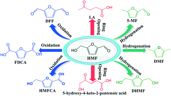
As the world demand for alternative sources of energy, chemicals and materials increases, renewable products derived from biomass are becoming increasingly important in the chemical manufacturing landscape.1–3 Thus, the major challenge is to convert biomass as a feedstock into useful chemicals through economically efficient chemical processes. One of the most attractive directions in biorefinery development is devoted to the production of furan derivatives, especially for furfural and 5-hydroxymethylfurfural (HMF). HMF, which is derived from the C6 sugar fraction of lignocellulosic biomass, was identified as one of the top ten bio-based platform chemicals with significant market potential.4 It is very useful not only as an intermediate for the production of the biofuel dimethylfuran (DMF) (Scheme 1), but also for other important chemicals such as 2,5-diformylfuran (DFF), 5-methylfuraldehyde (5-MF) levulinic acid, 5-hydroxy-4-keto-2-pentenoic acid and dihydroxymethylfuran etc.5,6In recent years, increasing attention has been devoted to transforming HMF into DFF, which is considered as a highly useful chemical with applications in pharmaceuticals, fungicides, organic conductors, macrocyclic ligands,7,8 and as the monomer of some special multifunctional polymers.9,10 DFF can be produced from HMF through the selective oxidation or dehydrogenation of the hydroxymethyl group, which are parts of a very complex process, including several parallel and consecutive reactions, such as over-oxidation, decarboxylation, ring-opening and cross-polymerization. The oxidation route can lead to over-oxidation, forming 5-hydroxymethylfuran-2-carboxylic acid (HMFCA) and furan dicarboxylic acid (FDCA).11–13 Although over-oxidation is not a concern in dehydrogenation, it is endothermic, which means higher temperatures are required, thus the side-reactions are more likely to occur. Therefore while there are reports of catalytic conversion of HMF to DFF, the studies of developing more economical and environmental catalysts in this instance are still on going.
In the early reports, some oxidants such as NaOCl, BaMnO4 and H2O2 were used to synthesize DFF from the oxidation of HMF.14–16 These methods not only required stoichiometric oxidants but also produced large amounts of waste. Recently, using O2 (or air) as oxidants has attracted more attention, with high HMF conversion and DFF selectivity reported in many works.17–19 But unfortunately, precious metal catalysts are needed in most of these reports, limiting industrialization. Additionally, the choice of solvent is another important consideration. To obtain higher activity or selectivity, most studies using dioxygen performed reactions in organic solvents.20,21 However, water is directly produced in the process of HMF production, and so it will be preferable to produce DFF or any other product from HMF without water separation. Therefore, it is an attractive topic to develop non-noble metal catalysts in the presence of water with the merits of low price, high efficiency and sustainability.
Besides DFF, 5-MF is also a very useful chemical among HMF derivatives, which can be used as intermediates in some synthetic routes.22,23 However, the synthesis of 5-MF from HMF is still a challenge, as the hydrogenation of the carbonyl group in HMF is kinetically more favorable than the hydrogenolysis of hydroxymethyl group.24 Furthermore, the expected product, 5-MF, thermodynamically has a strong tendency to be further hydrogenated to DMF under hydrogenation reaction conditions.25 Encouragingly, highly efficient synthesis of 5-MF from HMF with Nb2O5 supported single atom catalysts (SACs) was reported by Han et al. very recently, although noble metal such as Pt and Pd were used.26
In previous papers, some results on the behaviour of HMF and its reaction intermediates or derivatives (such as DFF, FDCA, HMFCA) over Cu-based catalysts are reported. For example, Tong et al. reported more than 90% yield of DFF from the oxidation of HMF using CuI/1-hydroxybenzotriazole as catalyst at reaction conditions of 130 °C and 0.3 MPa of O2.27 Ma et al. reported nearly 100% yield of DFF in acetonitrile with Cu(NO3)2–VOSO4 (1![[thin space (1/6-em)]](https://www.rsc.org/images/entities/char_2009.gif) :
:![[thin space (1/6-em)]](https://www.rsc.org/images/entities/char_2009.gif) 1) and 10 bar O2.9 However, those homogeneous methods generally suffer from the difficulty of separation and recovery of the copper catalysts. Therefore, some heterogeneous Cu-based catalysts also been investigated. For example, 75% HMF conversion and 51% selectivity to DFF was obtained on Cu–MnO2 catalyst.28 Zhou et al. prepared CuO/Al2O3 catalyst by electro-blowing spinning (EBS) method and used to catalyze the oxidation of HMF. FDCA was the primary product through HMFCA route.16 Ren et al. studied the activation of formyl C–H and hydroxyl O–H bonds in HMF by CuO.29 DFT calculations on CuO (111) surface suggest that the hydroxyl O–H bon breaking is likely to be the first step in HMF oxidation and results in the product of FDCA.
1) and 10 bar O2.9 However, those homogeneous methods generally suffer from the difficulty of separation and recovery of the copper catalysts. Therefore, some heterogeneous Cu-based catalysts also been investigated. For example, 75% HMF conversion and 51% selectivity to DFF was obtained on Cu–MnO2 catalyst.28 Zhou et al. prepared CuO/Al2O3 catalyst by electro-blowing spinning (EBS) method and used to catalyze the oxidation of HMF. FDCA was the primary product through HMFCA route.16 Ren et al. studied the activation of formyl C–H and hydroxyl O–H bonds in HMF by CuO.29 DFT calculations on CuO (111) surface suggest that the hydroxyl O–H bon breaking is likely to be the first step in HMF oxidation and results in the product of FDCA.
Besides oxidation, Cu-based heterogeneous catalysts have also been developed for hydrogenation reactions. Riisager et al. reported that HMF could be reduced in supercritical methanol by using copper-doped porous metal oxides (PMOs).30 Kumalaputri et al. also used the copper-doped PMOs to achieve tuneable and selective conversion of HMF to DMF and 2,5-furandimethanol (FDM).31 Very recently, Umasankar et al. reported the hydrogenation of HMF to 2,5-dimethylfuran (DMF) on SBA-16 supported NiCu bimetallic catalyst.32
In our previous work, Cu-based heterogeneous catalysts were adopted to activate the carbonyl or hydroxyl group in aldehyde-water shift reaction (AWS) to produce the corresponding carboxylic acid.33,34 However, when HMF was used under the same conditions, AWS reaction did not occur. Unlike on aliphatic aldehydes on Cu-based catalysts and HMF on CuO catalysts, the expected product FDCA, or even HMFCA, was not detectable. This phenomenon intrigued us to further explore how the HMF activated and reacted on copper based heterogeneous catalysts. In this work, to simplify the problem, bulk Cu was used to catalyze the transformation of HMF to understand how the Cu metal activates the carbonyl and/or hydroxyl groups. Meanwhile, to estimate the potential application of heterogeneous Cu catalysts in HMF transformation, Cu supported on the most common supports (Al2O3 and SiO2) and commercial CuZnAl catalysts were also adopted. Catalysts after use were characterized by quasi in situ XPS to confirm the element states on the surface and density function theory (DFT) calculations were used to help understand the reaction mechanisms.
2. Experimental
2.1 Materials
5-Hydroxymethylfurfural (HMF), 2,5-diformylfuran (DFF), 5-methylfuraldehyde (5-MF), silicon dioxide (SiO2, 20 nm), aluminium oxide (Al2O3, 20 nm), methanol, dimethyl sulfoxide (DMSO), dioxane and N,N-dimethylformamide were purchased from Macklin Biochemical Co. Ltd. Copper(II) nitrate hydrate (Cu(NO3)3·3H2O), sodium carbonate (Na2CO3), sodium hydroxide (NaOH), toluene, acetonitrile, were purchased from Sinopharm Chemical Reagent Co. Ltd. All the chemicals were of analytical grade. The other chemicals were purchased from local companies and used without further purification. Ultrapure water was used for the catalyst preparation and catalytic reactions.2.2 Catalyst preparation
The bulk copper oxide catalysts were prepared by co-precipitation method under similar controlled conditions using metal nitrate solutions as precursors. A mixture solution of NaOH and Na2CO3 with a molar ratio of 1![[thin space (1/6-em)]](https://www.rsc.org/images/entities/char_2009.gif) :
:![[thin space (1/6-em)]](https://www.rsc.org/images/entities/char_2009.gif) 1 was used as a precipitator. The two solutions were dropped synchronously into stirred deionized water at 50 °C and constant pH of 9 ± 0.2. The precipitate was aged in the mother liquor for 4 h. The formed hydroxides were then filtered, washed with deionized water to pH = 7, and dried at 110 °C overnight. The precursors were then calcined at 450 °C for 3 h with a temperature ramp of 1 °C min−1 to obtain the corresponding oxide catalysts.
1 was used as a precipitator. The two solutions were dropped synchronously into stirred deionized water at 50 °C and constant pH of 9 ± 0.2. The precipitate was aged in the mother liquor for 4 h. The formed hydroxides were then filtered, washed with deionized water to pH = 7, and dried at 110 °C overnight. The precursors were then calcined at 450 °C for 3 h with a temperature ramp of 1 °C min−1 to obtain the corresponding oxide catalysts.
The metal oxide-supported copper oxide catalyst was prepared by a simple equal volume impregnation method. Typically, an appropriate amount of Cu(NO3)3·3H2O was dissolved in deionized water and 5 g of support (Al2O3 or SiO2) was added to give 5 wt% of Cu deposition. The solution was stirred at 80 °C to evaporate the water. Then the obtained powder was dried at 110 °C overnight. The resulting powder was milled and sieved before the calcination process at 450 °C in static air for 3 h.
2.3 Catalyst characterization
X-ray diffraction (XRD) patterns were obtained using a PANalytical X-pert Pro MPD with Cu Kα radiation (λ = 0.154 nm). All binding energies (BEs) were corrected referencing the C 1s (284.6 eV) peak of adventitious carbon as an internal standard. The temperature programmed reduction (TPR) of H2 was performed on a home-made apparatus under a 10 vol% H2/Ar gas flow (40 ml min−1) at a rate of 10 °C min−1 up to 700 °C and using a thermal conductivity detector (TCD). To investigate if Cu could be re-oxidised by H2O, a normal H2-TPR was completed, before switching to a feed of 10% H2/Ar at 300 °C for 1 h (30 ml min−1). Then the gas-feed was switched to 30 ml min−1 He which was flowed through deionised water for 2 h at 260 °C. Finally a normal H2-TPR was carried out.The quasi in situ X-ray photoelectron spectroscopy (XPS) data were collected using a Thermo Scientific K-Alpha+ (Thermofisher; USA) with Al Kα (1486.6 eV) irradiation source. The quasi in situ XPS measurement method is to cool the reacted catalysts under different atmospheres to room temperature in a nitrogen atmosphere, vacuum seal the package, and directly move the sample in the glove box to the analysis room for testing. All binding energies (BEs) were corrected referencing the C1s (284.6 eV) peak of the contamination carbon as an internal standard.
2.4 Catalytic test
The catalytic transformation of HMF was carried out in a continuous flow fixed-bed system, using a quartz fixed-bed reactor under atmospheric pressure. In a typical experiment, 0.2 g of the catalyst was introduced into the reactor. The catalyst bed was packed with silica wool which serves as the preheated zone. Before the reaction, the catalysts were pre-reduced in a H2 stream at 300 °C for 2 h. 12.6 mg mL−1 HMF dissolved in different solvents was injected with a syringe pump at a flow rate of 1 mL h−1. The reactions were conducted under N2, H2 or air, keeping a constant flow rate of 10 mL min−1 by using mass flow controllers. The exhaust gas was directed through a cryogenic constant temperature tank, and the condensable gas was condensed in the collection tube. The liquid sample was analysed offline by gas chromatography equipped with a flame ionization detector (FID) detector, and the gas product was analyzed online by gas chromatography equipped with a TCD detector.2.5 Analytical methods
The liquid product was condensed with an ice bath and analyzed offline by GC with an Agilent 7820A apparatus equipped with an HP-5 (30 m × 320 μm × 0.25 μm) capillary column and an FID. In all of the analyses, the injection of 1 μL sample was done at 250 °C and a 50![[thin space (1/6-em)]](https://www.rsc.org/images/entities/char_2009.gif) :
:![[thin space (1/6-em)]](https://www.rsc.org/images/entities/char_2009.gif) 1 split ratio. The carrier gas was N2, flow rate was 10 mL min−1; The flow rate of H2 was 30 mL min−1, and the flow rate of air was 300 mL min−1; The detector temperature was set at 270 °C and pressure set at 4.95 psi. Chromatographic separations were carried out using temperature programming. The initial oven temperature was held at 50 °C for 2 min, then raised to 100 °C at 10 °C min−1, held at 100 °C for 5 min, raised to 250 °C at 15 °C min−1, and held for 5 min.
1 split ratio. The carrier gas was N2, flow rate was 10 mL min−1; The flow rate of H2 was 30 mL min−1, and the flow rate of air was 300 mL min−1; The detector temperature was set at 270 °C and pressure set at 4.95 psi. Chromatographic separations were carried out using temperature programming. The initial oven temperature was held at 50 °C for 2 min, then raised to 100 °C at 10 °C min−1, held at 100 °C for 5 min, raised to 250 °C at 15 °C min−1, and held for 5 min.
The gaseous products were trapped in a gas burette and analyzed by GC equipped with a TCD detector connected to a Porapak Q (3 m × 30 mm) packed column. Carrier gas was N2 at 30 mL min−1, and the temperature of oven and detector were 50 and 100 °C; gasification temperature set to 100 °C.
We calculated the HMF, DFF, and 5-MF contents in the samples using an external standard calibration curve that had been constructed based on the pure compounds.
Repeated runs showed that data variation was in the range of ±10% (relative value).
2.6 Methods and models for DFT calculations
All calculations were performed using the Vienna ab initio simulation package (VASP),35 where the ionic cores are described by the projector augmented wave (PAW) method. The generalized gradient approximation and the Perdew–Burke–Ernzerhof functional (GGA-PBE) were used to describe the exchange and correlation energies for all system,36 and considering the long-range dispersion correction PBE-D3 functional for vdW interaction.37 According to King et al., the effect of spin polarization was small,38 so spin polarization was not considered in this calculation. The electronic wave functions were expanded in a plane wave basis where the kinetic cut-off energy was 400 eV. The convergence criteria for the electronic self-consistent iteration and force were set to 10−6 eV and 0.01 eV Å−1, respectively.A 4 × 4 Cu (111) surface with a thickness of three atomic layers was employed for all calculations. The bottom layer was frozen, and the top two layers were allowed to relax. The vacuum layer between periodically repeated slabs was set as 15 Å to avoid interactions among slabs. The Brillouin zone was sampled with a 3 × 3 × 1 k-point grid. Surface relaxation was performed until all forces were smaller than 0.01 eV Å−1. The calculation details for 4 × 8 Cu0/Cu+ interface is exactly same with those of Cu (111) surface, except the Brillouin zone was sampled with a 2 × 1 × 1 k-point grid. The structures of transition states (TSs) and reaction barriers of elementary steps were located using the climbing image nudged elastic band (CI-NEB) or the dimer methods.39,40 The transition states corresponding to the reaction coordinate along the reaction pathway were verified by the stretching frequencies with only one imaginary frequency.
The adsorption energies (Ead) are defined as
| Ead = Etotal − (Esurface + Eadsorbate) | (1) |
| Ea = E(TS) − E(IS) | (2) |
3. Results and discussion
3.1 Characterization of fresh catalysts
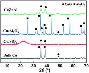
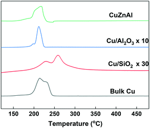
XRD analysis was carried out to identify the phase of catalysts before and after use. As can be seen from Fig. 1, the bulk CuO catalyst before use showed two peaks at 2θ = 35.5 and 38.8° which is the typical CuO diffraction pattern. Due to the high CuO content (65 wt%), a similar XRD pattern was also observed for the commercial CuZnAl catalyst, although the peaks were broader. The Al2O3 and SiO2 supported samples showed much broader, less intense reflections due to the low content (5 wt%) and high dispersion of CuO on the two supports. After reduction and use in the catalytic reaction, as Fig. S4† shows, the copper oxide species were reduced to Cu0 for all of the catalysts. As can be seen, the diffraction peaks of CuO disappeared, while characteristic diffraction peaks of Cu0 emerged at 43.3 and 50.4°, due to the crystal faces (111) and (200), respectively.H2-TPR analysis was performed to investigate the reducibility of the Cu-based catalysts. For convenient comparison, the profiles of Cu/Al2O3 and Cu/SiO2 were amplified by 10 and 30-fold respectively. As can be seen from Fig. 2, most of the catalysts showed main reduction peaks at around 220 °C with one or more shoulder peaks, which indicates the reduction process took place in steps. This is commonly observed over supported Cu catalysts and has been explained by surface CuO initially reducing, followed by the reduction of bulk CuO.41 The Cu/SiO2 sample exhibited a higher reduction temperature than the others, suggesting a strong metal–support interaction than in the Cu/Al2O3 and CuZnAl catalysts.42 The lower peak at 228 °C could be attributed to the reduction of CuO species, while the higher peak at 257 °C represents the reduction of CuO in CuO/SiO2 interface, sometimes copper phyllosilicate species formed by copper–support interaction as Guerreiro et al. suggested.43 A shift to a higher temperature has also been reported to be cause by more crystalline CuO, although this is not apparent from the XRD patterns shown in Fig. 1.41
3.2 Catalytic performance in HMF transformation
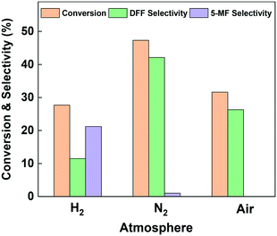
HMF transformation was performed in a continuous flow fixed-bed reactor at 260 °C and ambient pressure. An aqueous solution of HMF (1.26 wt%) was used as the reactant and pumped into the reactor. Liquid products were collected between 2 and 3 hours' run. To investigate the effect of reaction atmosphere on the reaction pathways, over Cu-based catalysts, we firstly performed the reaction on the bulk copper oxide catalyst under nitrogen, hydrogen and air. As can be seen from Fig. 3, the two main detectable products on the bulk Cu catalyst are DFF and 5-MF. Owing to the great reactivity and instability of HMF in water, more than 50% of the consumed reactant was polymerized or converted into minor by-products.44 The most favorable product over bulk CuO when under oxidative and inert atmosphere was DFF. Compared to nitrogen atmosphere, the conversion of HMF under air decreased from 47.3% to 31.6%, and the DFF selectivity significantly decreased from 42.1% to 26.3%. Thus, we speculate the formation of DFF on Cu surface is mainly through the dehydrogenation pathway. The presence of oxygen blocked part of the Cu active center and further enhanced side reactions. Interestingly, under pure hydrogen atmosphere the dehydrogenation was severely suppressed: the selectivity to DFF was just 11.5%, while the selectivity to 5-MF increased to 21.2%. The above results indicate that dehydrogenation is the most favorable reaction channel for HMF on the Cu catalyst, and HDO is be more significant when under hydrogen atmosphere. Post-reaction XRD analysis (Fig. S1†) revealed that the dominant phase after all of the reactions is Cu0. However, in the case of the sample reacted with air, Cu2O was observed in addition to Cu0.The chemical states of copper on the bulk Cu catalyst's surface after in situ reduction and use under various atmosphere were investigated by the quasi in situ XPS analysis. As can be seen from Fig. 4(A), all the samples showed binding energies of about 931.6 and 951.4 eV, which were the characteristic peaks of 2p3/2 and 2p1/2 for Cu0/Cu+ species, and almost no Cu2+ peak was found.45 Since the Cu0 and Cu+ species can't be distinguished by Cu 2p spectra, Fig. 4(B) shows the Cu LMM Auger electron spectra. It can be found that both of the samples used under N2 and H2 atmosphere exhibit double peak structure at binding energy of 566.9 and 569.1 eV, which could be assigned to Cu0 and Cu+ respectively.46 That is to say, both of the two samples showed Cu0 and Cu+ mixture on the surface. Since they were under inert or even reducing atmosphere, the Cu+ species must come from the oxidation of Cu0 by H2O. On the contrary, the sample used under air showed mainly Cu+ species with almost no peak at 566.9 eV found. Combined with the reaction results, we may draw the conclusion that water derived Cu0/Cu+ mixture is suitable for the catalytic transformation of HMF. In order to probe this further, we carried out a H2-TPR experiment on the catalyst, then fed H2O/He over the sample at 260 °C for 0.5 h, before measuring an additional H2-TPR. This is shown in Fig. S2† and confirmed that re-oxidation of the Cu occurred, the profile of second TPR was amplified 30 times to aid comparison. Evidence of Cu oxidation by H2O has previously been reported by Sushkevich et al. for Cu–zeolite catalysts for methane oxidation to methanol.47
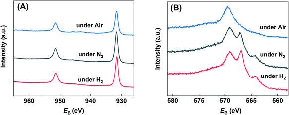 | ||
| Fig. 4 Quasi in situ XPS analysis of used catalysts under various atmospheres. A) Cu 2p region and B) Cu Auger LMM region. | ||
To clarify the potential applications of Cu-based catalysts in the heterogeneous catalytic conversion of HMF, the commercial CuZnAl and the most common carrier supported catalysts such as Cu/SiO2, Cu/Al2O3 were also tested. Reactions were performed under N2 atmosphere and the results are summarized in Table 1. As can be seen, higher HMF conversion was obtained on the commercial CuZnAl, which increased from 47.3% in bulk Cu to 67.6%. However, there was little change in the selectivity of desired products. In contrast, on the dispersed catalysts made by impregnation method, the selectivity was greatly improved. The Cu/Al2O3 catalyst exhibited a selectivity of 79.2% for DFF and 16.3% for 5-MF, leading to only about 4.5% selectivity to undesired side reactions. In order to evaluate the stability of the prepared catalysts, a time on-line study was carried out. These data are presented in Fig. S3.† In each case, the catalysts deactivated on-stream but at different rates. Table 1 shows the activity retained after 10 h on-stream. There is a large difference in the values observed, where Cu/Al2O3 is the most stable, and retained 70% of its initial activity. This was followed by CuZnAl, Cu/SiO2 and bulk CuO, which retained 57, 44 and 37% of their initial activity. Post-reaction XRD of the samples is presented in Fig. S4.† In each case, only Cu0 reflections were observed, showing that the complete reduction of Cu took place under the reaction conditions. The likely explanation for the deactivation is the blocking of active sites i.e. by humins and possibly the loss of Cu surface area via sintering. The enhanced stability of Cu/Al2O3 may be linked to both minimal humin formation as well as a strong anchoring of Cu on the support.
| Samples | Conversion (%) | Selectivity (%) | Activity retained after 10 h on-stream (%) | ||
|---|---|---|---|---|---|
| DFF | 5-MF | Others | |||
| Blank | 0.5 | 0 | 0 | — | — |
| Bulk CuO | 47.3 | 42.1 | 1.0 | 56.9 | 37 |
| Cu/Al2O3 | 47.7 | 79.2 | 16.3 | 4.5 | 70 |
| Cu/SiO2 | 52.5 | 71.2 | 12.0 | 16.8 | 44 |
| CuZnAl | 67.6 | 48.1 | 5.9 | 46.0 | 57 |
It is instructive to compare the performance of the Cu catalysts in a fixed bed flow reactor with the literature reports of 5-HMF transformation to DFF. Table S1† shows a summary of literature reports, which have been carried out in the liquid phase. As this is the first report of 5-HMF transformation to DFF in the gas-phase, there is no direct comparison available. The key differences between the current work and the literature reports are that the gas-phase transformation takes place at higher temperature (260 °C) than the liquid phase reaction (typically 90–130 °C), which also requires relatively high pressures of O2 (3–30 bar). In the current work, it has been shown that H2O can in principle be used in place of high pressures of O2, which is desirable from a safety point of view in the context of a large scale process. The space time yield (STY) of the literature reports has also been calculated and is in the range of 0.7–19.4 mmolDFF gcat−1 h−1. The STYs of the Cu catalysts prepared in the current work were 1.8–2.5 mmolDFF gcat−1 h−1. It is noteworthy that the literature reports that outperform the Cu catalysts, were carried out at 20–30 bar O2 and or included toxic solvents, which is not desirable from a green chemistry perspective. The STY of the current Cu catalysts can be considered to be competitive with many of the literature reports.
According to the numerous previous reported works in autoclave reactor, the solvent plays an important role in the transformation of HMF.13,28,48 In fact, most of them were performed in various organic solvents to obtain better conversion or selectivity. Therefore, to investigate the influence of solvent on the Cu-based heterogeneous catalyst in continuous flow fixed-bed reactor, we also tested some of the organic solvents that often appeared in the previous works, and the results are summarized in Table 2. For the convenience of comparison, the concentration of HMF in organic solvents were in consistent with that in water (1.26 wt%). From a practical perspective, we are most concerned about the selectivity of target products, i.e. the DFF and 5-MF. Although more than 90% conversion was obtained in the solvents of methanol and acetonitrile, the selectivity is very poor. Almost all of the converted HMF transformed to high molecular weight products, i.e. humins. As shown in Fig. 5(A), the higher conversion of HMF in organic solvents, the more selective to undesired missing products. As an exception, although sometimes DMSO is a good solvent in liquid phase aerobic oxidation,49,50 here in the gas-phase continuous-flow reaction it showed much higher selectivity to humins that seriously deviate from the correlation between conversion and selective to humins (Fig. 5(A)). We speculate the deviation could attributes to the incomplete vaporization of DMSO (boiling point of 189 °C, much higher than other investigated solvents). According to the chosen solvents, we can draw a preliminary conclusion that organic solvents should be avoided to use in the fixed-bed reactor when using Cu-based catalyst, either from a practical perspective or from an environmentally friendly perspective.
| Samples | E ad (eV) | Conversion (%) | Selectivity (%) | ||
|---|---|---|---|---|---|
| DFF | 5-MF | Others | |||
| a DMSO: dimethyl sulphoxide. | |||||
| Methanol | −0.55 | 94.4 | 6.1 | 5.9 | 88.0 |
| Ethanol | −0.68 | 99.2 | 1.3 | 1.6 | 97.1 |
| 1-Propanol | −0.81 | 64.7 | 28.5 | 41.0 | 30.5 |
| Acetonitrile | −0.67 | 94.8 | 3.1 | 2.9 | 94.0 |
| Dioxane | −0.91 | 74.0 | 42.9 | 8.2 | 48.9 |
| DMSOa | −1.21 | 26.5 | 21.6 | 7.5 | 70.9 |
| Water | −0.40 | 59.8 | 66.5 | 8.8 | 24.7 |
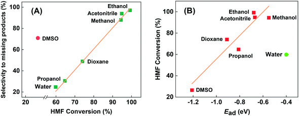 | ||
| Fig. 5 The relationship between HMF conversion and selectivity to undesired missing products (A), and between HMF conversion and adsorption energy of solvents (B). | ||
Moreover, after we calculated the adsorption energy (Ead) of solvents by DFT, we found that the conversion of HMF in organic solvents seems to correlate with the Ead of solvents. As Fig. 5(B) shows, low Ead of methanol and acetonitrile gave the highest conversion, while the high Ead of DMSO gave the lowest conversion of HMF. They can be almost described in linear relationships, which could be attributed the competitive adsorption of HMF and solvents. Unlike with the reaction in the autoclave reactor, reactants in fixed-bed reactor were in the gas phase rather than liquid phase, so the solvent effect is mainly reflected in the effects of adsorption behavior. Stronger adsorption of solvents will block much more active centers, especially for the strong centers on catalyst surface leading to lower activity, and vice versa. The same explanation may be proposed for explaining the inhibition of the reaction under a H2 atmosphere. We can see that water severely deviates from the linear relationship formed by organic solvents in the Fig. 5(B). Even if water has much lower Ead than methanol and acetonitrile, it showed only 59.5% of HMF conversion, but much higher selectivity. This phenomenon indicates that water may participate in the catalytic transformation of HMF through dissociative adsorption, even though it is not a reactant. The role of water in the reaction will be discussed below with DFT results.
3.3 DFT studies
To better understand the microscopic reaction mechanism of HMF transformation on the heterogeneous Cu catalyst, DFT was adopted to calculate the energy changes of some of the steps in reaction route. It is well-known that the first step of the heterogeneous-catalyzed reaction is chemisorption of reactants. In this work, the chemisorption of HMF is obviously the most critical first step and our DFT studies began from this.Among the low-index surfaces, the Cu (111) surface is found to have the lowest surface energy and represents the most stable surface.51,52 Therefore, we chose the Cu (111) surface to perform our computational work. Although HMF has four isomers, two of them are obviously stable than others. Ren et al. investigated the adsorption of the two stable isomers on CuO (111) surface, and results showed that only 0.07 eV difference in adsorption energy between their most stable configurations, therefore only the most stable isomer of HMF was considered in this work.29 According to Greeley et al. van der Walls-correction (vdW-correction) is necessary for furfural and furfural alcohol adsorption on Cu (111) surface.53 We also compared the adsorption of HMF with and without van der Waals correction. When using the standard DFT functionals, HMF tends to adsorb upright on the Cu surface with a very small Ead of around 0.2 eV, which is in the same order of magnitude as physical adsorption. Instead, when the van der Waals-corrected density functionals used, a parallel configuration was the favoured mode for HMF, and the Ead is much bigger than before. Thus, the DFT-D3 method was adopted in all of the calculations in this work.
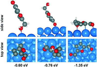
Plausible adsorption configurations of HMF over Cu (111) surface were built up and can be classified into three types: (a) upright adsorption of the hydroxyl group, (b) upright adsorption of the carbonyl group and (c) parallel-ring adsorption. As shown in Fig. 6, among the four types of adsorption position on Cu (111) surface (top, bridge, fcc and hcp), the top site is most stable for adsorption mode (a), while the bridge site is more stable for mode (b). The optimized Cu–O bond lengths in these two modes are 2.206 and 2.176 Å (average of 2.175 and 2.177 Å) respectively. However, both of them showed much lower adsorption energy (−0.60 and −0.76 eV, respectively) than the mode (c) of parallel-ring adsorption (−1.35 eV). Therefore, the most favorable adsorption configuration for HMF over Cu (111) surface is parallel, although it's possible that the Ead been overestimated due to the vdW-correction.
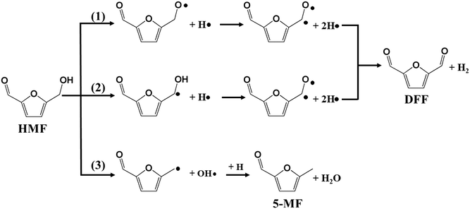
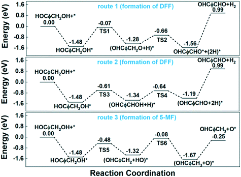
In our previous work, furfural was tested on the Cu-based catalysts under comparative reaction conditions,34 but almost no conversion of furfural was observed. Therefore, the carbonyl group on the furan ring can't be transformed under the employed reaction conditions, thus it will be ignored in this work. The reaction on the hydroxyl group can give the two main detectable products of DFF and 5-MF by dehydrogenation and HDO respectively. The plausible reaction routes for these two products are shown in Scheme 2. Route 1 and route 2 represents the formation of DFF through dehydrogenation, while route 3 the formation of 5-MF via HDO.
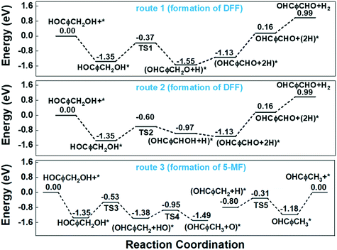
Route 1 begins with the scission of O–H bond on hydroxyl group, leading to the alkoxyl intermediate (OHCφCH2OH–H → OHCφCH2O, φ represents furan ring). The formed OHCφCH2O can be further dehydrogenated to DFF (OHCφCH2O–H → OHCφCHO) and desorbed to gas phase. Route 2 begins with the scission of C–H bond from methylene, and followed by the dehydrogenation from hydroxyl bond to form the final product of DFF. The calculated energy profile for the two routes on Cu (111) surface is presented in Fig. 7. As can be seen, the first step of route 1 that scission of O–H bond is an exothermic process with the reaction energy of −0.20 eV, while the first step of route 2 that scission of C–H bond is endothermic with 0.38 eV. The activation energy (Ea) for these two steps are 0.98 and 0.75 eV respectively, much higher than on the CuO (111) and noble metals.29,54 Compared to route 1, the relatively lower Ea of route 2 made it's the more favorable route for dehydrogenation process. However, the high Ea and the endothermic nature make it necessary that the gas-phase reaction occur at high temperature. In this work, the optimized temperature is 260 °C, much higher than on CuO and noble metals.29
To investigate the HDO process of HMF on Cu (111) surface, we began by calculating the cleavage of the C–O bonds in the hydroxymethyl group. The DFT calculation results show the first step is a slightly exothermic process with reaction energy of only −0.03 eV, while the activation energy is as high as 0.82 eV. Additionally, the desorption energy (Ed) of the final product of 5-MF is as high as 1.18 eV. The high reaction barrier and desorption energy of product leading to the low selectivity of 5-MF on Cu-based catalysts, especially when using organic solvents.
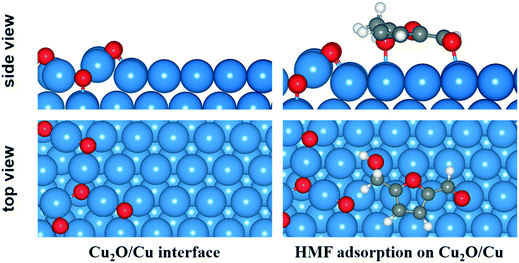
According to the XPS and TPR analysis, the surface Cu0 could be partly oxide to Cu+ and coexistence with Cu0 on the catalyst surface under reaction conditions. Therefore, slab model of Cu0/Cu+ mixture was also built to investigate the reactions at Cu0/Cu+ interface.55 A 4 × 8 supercell of Cu (111) surface with a thickness of three atomic layers was employed and 6 O atoms were deposited on the surface on the basis of a Cu2O (111) surface structure. The optimized structure of Cu0/Cu+ interface and adsorption configuration of HMF on the surface are shown in Fig. 8. Compared to on the Cu (111) surface, the Ead of HMF at the interface increased to −1.48 eV due to the interaction between hydrogen from HMF and surface O atom.
Similar with the pure Cu (111) surface, the more favourable route for dehydrogenation process at Cu0/Cu+ interface is also route 2 that begins with the scission of C–H bond. As can be seen from the potential energy diagram in Fig. 9, although route 1 and route 2 showed similar Ea of the second dehydrogenation step, they are quite different in the first step. The Ea of the first dehydrogenation step is as high as 1.41 eV in route 1, while which is about 0.87 eV in route 2. Therefore, route 1 is preferred for the dehydrogenation of HMF to form DFF.
For the HDO process, the Ea of the first step of C–O bond cleavage at Cu0/Cu+ interface is about 1.00 eV, which is slightly higher than C–H bond cleavage. For the second step, considering high concentration of O atom (or protonated counterpart OH group) and lack of H atom at the Cu0/Cu+ interface, we calculated the energy requirement for hydrogen transfer from adsorbed hydroxyl group to the methylene group to form the final HDO product 5-MF. Although the hydroxyl group can be produced by the first step of C–O bond cleavage i.e. very near the methylene group, the calculated Ea for the hydrogen transfer is as high as 1.24 eV. As a comparison, the Ea for direct hydrogenation on Cu (111) surface is only about 0.49 eV as shown in Fig. 7. Therefore, the conclusion is that high concentration of surface O atoms induced by partial oxidation greatly impedes the formation of 5-MF.
The experimental results above show that water exhibits a promoting effect on product selectivity when compared to most of the organic solvents. To understand the role of water in the reaction, we calculated the co-adsorption of water on Cu (111) surface to evaluate the impact of water on the transformation of HMF. The most stable adsorption site for H2O is the top site with the Ead of −0.40 eV (Table 2), which looks like physisorption. For the dissociated water, the most favorable configuration is fcc site for hydroxyl group and the opposite hcp for H atom, both of them share one surface Cu. We set the above two configurations as the initial and final states respectively, then the calculated Ea for water dissociation is 1.19 eV, which is a relatively high barrier.56 However, after water dissociation, the existence of the OH group significantly enhanced the scission of the O–H bond in HMF to trigger the dehydrogenation reaction. The Ea for the first step decreased from 0.98 to 0.18 eV, make the dehydrogenation reaction more easily. Moreover, beyond alkoxyl intermediate, water is the only by-product in this step, which is quite easy to desorb from Cu surface for the Ed (desorption energy) is as low as 0.40 eV. Similar results were also obtained in the HDO process. For the first step of OH group leaving from HMF, the existence of H atom decreased the Ea from 0.82 to 0.13 eV, obviously benefit to the reaction. However, the high desorption energy of the 5-MF product is still a huge barrier to achieve a considerable selectivity of 5-MF.
Conclusions
Cu-Based catalysts were used to catalyze the transformation of HMF on continuous flow fixed-bed reactor. The affecting factors such as atmosphere and solvents were studied in detail. Quasi in situ XPS analysis confirmed Cu0 species are the primary active center for the dehydrogenation and HDO reactions. DFT calculations were adopted to help understand the mechanisms of HMF transformation on Cu-based catalyst. From the results obtained, the following major conclusions were drawn:1. DFF and 5-MF can be produced from HMF on continuous fixed-bed reactor with Cu-based catalysts. HDO product of 5-MF is preferred under reducing atmosphere of H2, while dehydrogenation product of DFF is dominant under oxidizing atmosphere of air. However, the inert atmosphere of N2 gives the highest conversion and total selectivity of detectable products.
2. Carrier dispersed Cu catalysts such as Cu/Al2O3 and Cu/SiO2 can help to improve the total selectivity of detectable products. The highest DFF selectivity of 79.2% and 5-MF selectivity of 16.3% was obtained on Cu/Al2O3 catalyst.
3. Compared to organic solvents, water is the preferred solvent for gas phase conversion of HMF on Cu-based catalysts. DFT calculation results indicate that OH group and H atom dissociated from co-adsorbed water can remarkably enhance the leaving of H or OH group from HMF, thus improve the catalytic performance of Cu catalysts.
In conclusion, Cu-based catalysts can be used to catalyze the transformation of HMF to produce DFF and 5-MF in gas phase. However, the catalyst needs better understanding and further improvement to meet the needs of industrialization, which will be the subject of future work.
Conflicts of interest
The authors declare that they have no known competing financial interests or personal relationships that could have appeared to influence the work reported in this paper.Acknowledgements
The project was supported by Hefei Municipal Natural Science Foundation (2021043) and the Fundamental Research Funds for the Central Universities (JZ2017HGTB0231).References
- Q. S. Kong, X. L. Li, H. J. Xu and Y. Fu, Fuel Process. Technol., 2020, 209, 106528 CrossRef CAS
.
- H. Xu, Z. Wang, J. Huang and Y. Jiang, Energy Fuels, 2021, 35, 8602–8616 CrossRef CAS
.
- Q. Hou, X. Qi, M. Zhen, H. Qian, Y. Nie, C. Bai, S. Zhang, X. Bai and M. Ju, Green Chem., 2021, 23, 119–231 RSC
.
- A. A. Rosatella, S. P. Simeonov, R. F. M. Frade and C. A. M. Afonso, Green Chem., 2011, 13, 754–793 RSC
.
- H. Xia, S. Xu, H. Hu, J. An and C. Li, RSC Adv., 2018, 8, 30875–30886 RSC
.
- H. Wang, C. Zhu, D. Li, Q. Liu, J. Tan, C. Wang, C. Cai and L. Ma, Renewable Sustainable Energy Rev., 2019, 103, 227–247 CrossRef CAS
.
- D. A. Giannakoudakis, V. Nair, A. Khan, E. A. Deliyanni, J. C. Colmenares and K. S. Triantafyllidis, Appl. Catal., B, 2019, 256, 117803 CrossRef CAS
.
- K. T. Hopkins, W. D. Wilson, B. C. Bender, D. R. McCurdy, J. E. Hall, R. R. Tidwell, A. Kumar, M. Bajic and D. W. Boykin, J. Med. Chem., 1998, 41, 3872–3878 CrossRef CAS PubMed
.
- J. Ma, Z. Du, J. Xu, Q. Chu and Y. Pang, ChemSusChem, 2011, 4, 51–54 CrossRef CAS PubMed
.
- A. S. Amarasekara, D. Green and L. T. D. Williams, Eur. Polym. J., 2009, 45, 595–598 CrossRef CAS
.
- Y. Yan, K. Li, J. Zhao, W. Cai, Y. Yang and J. M. Lee, Appl. Catal., B, 2017, 207, 358–365 CrossRef CAS
.
- D. X. Martínez-Vargas, J. Rivera De La Rosa, L. Sandoval-Rangel, J. L. Guzmán-Mar, M. A. Garza-Navarro, C. J. Lucio-Ortiz and D. A. De Haro-Del Río, Appl. Catal., A, 2017, 547, 132–145 CrossRef
.
- Z. Yang, B. Zhu, Y. He, G. Zhang, P. Cui and J. He, New J. Chem., 2021, 45, 16482–16489 RSC
.
- B. C. Li, J. Lee, E. Kwon, B. X. Thanh, J. Y. Lin, S. You, C. H. Lin and K. Y. A. Lin, J. Taiwan Inst. Chem. Eng., 2021, 126, 189–196 CrossRef CAS
.
- S. Li, K. Su, Z. Li and B. Cheng, Green Chem., 2016, 18, 2122–2128 RSC
.
- X. Zhou, K. Song, Z. Li, W. Kang, H. Ren, K. Su, M. Zhang and B. Cheng, Ceram. Int., 2019, 45, 2330–2337 CrossRef CAS
.
- Y. Liu, T. Gan, Q. He, H. Zhang, X. He and H. Ji, Ind. Eng. Chem. Res., 2020, 59, 4333–4337 CrossRef CAS
.
- Y. Zhu, M. Shen, Y. Xia and M. Lu, Catal. Commun., 2015, 64, 37–43 CrossRef CAS
.
- A. Buonerba, S. Impemba, A. D. Litta, C. Capacchione, S. Milione and A. Grassi, ChemSusChem, 2018, 11, 3139–3149 CrossRef CAS PubMed
.
- J. Xu, T. Su, Z. Zhu, N. Chen, D. Hao, M. Wang, Y. Zhao, W. Ren and H. Lü, Chem. Eng. J., 2020, 396, 125303 CrossRef CAS
.
- L. Ding, W. Yang, L. Chen, H. Cheng and Z. Qi, Catal. Today, 2020, 347, 39–47 CrossRef CAS
.
- M. E. Jung and G. Y. J. Im, J. Org. Chem., 2009, 74, 8739–8753 CrossRef CAS PubMed
.
- W. Wang, X. M. Zhao, J. L. Wang, X. Geng, J. F. Gong, X. Q. Hao and M. P. Song, Tetrahedron Lett., 2014, 55, 3192–3194 CrossRef CAS
.
- R. Goyal, B. Sarkar, A. Bag, N. Siddiqui, D. Dumbre, N. Lucas, S. K. Bhargava and A. Bordoloi, J. Catal., 2016, 340, 248–260 CrossRef CAS
.
- Y. Nakagawa, M. Tamura and K. Tomishige, ACS Catal., 2013, 3, 2655–2668 CrossRef CAS
.
- S. Li, M. Dong, J. Yang, X. Cheng, X. Shen, S. Liu, Z. Q. Wang, X. Q. Gong, H. Liu and B. Han, Nat. Commun., 2021, 12(121), 1–9 Search PubMed
.
- X. Tong, Y. Sun, X. Bai and Y. Li, RSC Adv., 2014, 4, 44307–44311 RSC
.
- X. Tong, L. Yu, H. Chen, X. Zhuang, S. Liao and H. Cui, Catal. Commun., 2017, 90, 91–94 CrossRef CAS
.
- J. Ren, K. He Song, Z. Li, Q. Wang, J. Li, Y. Wang, D. Li and C. K. Kim, Appl. Surf. Sci., 2018, 456, 174–183 CrossRef CAS
.
- T. S. Hansen, K. Barta, P. T. Anastas, P. C. Ford and A. Riisager, Green Chem., 2012, 14, 2457–2461 RSC
.
- A. J. Kumalaputri, G. Bottari, P. M. Erne, H. J. Heeres and K. Barta, ChemSusChem, 2014, 7, 2266–2275 CrossRef CAS PubMed
.
- S. Umasankar, P. Tamizhdurai, P. Santhana Krishnan, S. Narayanan, V. L. Mangesh and K. Shanthi, Biomass Bioenergy, 2020, 143, 105868 CrossRef CAS
.
- T. Ye, Y. Ai, B. Chen, Y. Ye, J. Sun, L. Qin and X. Yao, Catal. Commun., 2021, 149, 106262 CrossRef CAS
.
- Y. Ye, B. Chen, X. Li, Y. Ai, J. Sun, G. Ni, L. Qin and T. Ye, ChemistrySelect, 2021, 6, 1976–1983 CrossRef CAS
.
- G. Kresse and J. Furthmüller, Phys. Rev. B: Condens. Matter Mater. Phys., 1996, 54, 11169 CrossRef CAS PubMed
.
- J. P. Perdew, K. Burke and M. Ernzerhof, Phys. Rev. Lett., 1996, 77, 3865 CrossRef CAS PubMed
.
- S. Grimme, J. Antony, S. Ehrlich and H. Krieg, J. Chem. Phys., 2010, 132, 154104 CrossRef PubMed
.
- Q. Ge, S. J. Jenkins and D. A. King, Chem. Phys. Lett., 2000, 327, 125–130 CrossRef CAS
.
- G. Henkelman, B. P. Uberuaga and H. Jónsson, J. Chem. Phys., 2000, 113, 9901–9904 CrossRef CAS
.
- G. Henkelman and H. Jónsson, J. Chem. Phys., 1999, 111, 7010–7022 CrossRef CAS
.
- K. V. R. Chary, G. V. Sagar, C. S. Srikanth and V. V. Rao, J. Phys. Chem. B, 2006, 111, 543–550 CrossRef PubMed
.
- Y. T. Qi, C. H. Zhe, X. Ning, Y. T. Qi, C. H. Zhe and X. Ning, Russ. J. Phys. Chem. A, 2018, 92, 449–455 CrossRef CAS
.
- E. D. Guerreiro, O. F. Gorriz, G. Larsen and L. A. Arrúa, Appl. Catal., A, 2000, 204, 33–48 CrossRef CAS
.
- S. B. Kim, S. J. You, Y. T. Kim, S. Lee, H. Lee, K. Park and E. D. Park, Korean J. Chem. Eng., 2011, 28, 710–716 CrossRef CAS
.
- T. Q. Ye, Z. X. Zhang, Y. Xu, S. Z. Yan, J. F. Zhu, Y. Liu and Q. X. Li, Wuli Huaxue Xuebao, 2011, 27, 1493–1500 CAS
.
- S. Velu, K. Suzaki and C. S. Gopinath, J. Phys. Chem. B, 2002, 106, 12737–12746 CrossRef CAS
.
- V. L. Sushkevich, D. Palagin, M. Ranocchiari and J. A. Van Bokhoven, Science, 2017, 356, 523–527 CrossRef CAS PubMed
.
- F. Neaţu, N. Petrea, R. Petre, V. Somoghi, M. Florea and V. I. Parvulescu, Catal. Today, 2016, 278, 66–73 CrossRef
.
- H. Zhang, J. H. Clark, T. Geng, H. Zhang and F. Cao, ChemSusChem, 2021, 14, 456–466 CrossRef CAS PubMed
.
- J. Nie, J. Xie and H. Liu, J. Catal., 2013, 301, 83–91 CrossRef CAS
.
- L. Vitos, H. L. Skriver and J. Kollár, Surf. Sci., 1999, 425, 212–223 CrossRef CAS
.
- J. L. F. Da Silva, C. Barreteau, K. Schroeder and S. Blügel, Phys. Rev. B: Condens. Matter Mater. Phys., 2006, 73, 12 CrossRef
.
- B. Liu, L. Cheng, L. Curtiss and J. Greeley, Surf. Sci., 2014, 622, 51–59 CrossRef CAS
.
- Q. Meng, D. Cao, G. Zhao, C. Qiu, X. Liu, X. Wen, Y. Zhu and Y. Li, Appl. Catal., B, 2017, 212, 15–22 CrossRef CAS
.
- T. T. Xiao and G. C. Wang, Catal. Sci. Technol., 2020, 10, 7640–7651 RSC
.
- A. A. Phatak, W. N. Delgass, F. H. Ribeiro and W. F. Schneider, J. Phys. Chem. C, 2009, 113, 7269–7276 CrossRef CAS
.
Footnote |
| † Electronic supplementary information (ESI) available. See DOI: https://doi.org/10.1039/d1cy02197d |
| This journal is © The Royal Society of Chemistry 2022 |

