
 Open Access Article
 This Open Access Article is licensed under a
 Creative Commons Attribution 3.0 Unported Licence
A guide to nanoscale IR spectroscopy: resonance enhanced transduction in contact and tapping mode AFM-IR
Jeffrey J.
Schwartz
 ab,
Devon S.
Jakob
bc and
Andrea
Centrone
*b
ab,
Devon S.
Jakob
bc and
Andrea
Centrone
*b
aLaboratory for Physical Sciences, College Park, MD 20740, USA
bNanoscale Device Characterization Division, Physical Measurement Laboratory, National Institute of Standards and Technology, 100 Bureau Drive, Gaithersburg, MD 20899, USA. E-mail: andrea.centrone@nist.gov
cInstitute for Soft Matter Synthesis and Metrology, Georgetown University, 3700 O St., NW Washington D.C., 20057, USA
First published on 26th May 2022
Abstract
Infrared (IR) spectroscopy is a broadly applicable, composition sensitive analytical technique. By leveraging the high spatial resolution of atomic force microscopy (AFM), the photothermal effect, and wavelength-tunable lasers, AFM-IR enables IR spectroscopy and imaging with nanoscale (< 10 nm) resolution. The transduction of a sample's photothermal expansion by an AFM probe tip ensures the proportionality between the AFM-IR signal and the sample absorption coefficient, producing images and spectra that are comparable to far-field IR databases and easily interpreted. This convergence of characteristics has spurred robust research efforts to extend AFM-IR capabilities and, in parallel, has enabled AFM-IR to impact numerous fields. In this tutorial review, we present the latest technical breakthroughs in AFM-IR spectroscopy and imaging and discuss its working principles, distinctive characteristics, and best practices for different AFM-IR measurement paradigms. Central to this review, appealing to both expert practitioners and novices alike, is the meticulous understanding of AFM-IR signal transduction, which is essential to take full advantage of AFM-IR capabilities. Here, we critically compile key information and discuss instructive experiments detailing AFM-IR signal transduction and provide guidelines linking experimental parameters to the measurement sensitivity, lateral resolution, and probed depth. Additionally, we provide in-depth tutorials on the most employed AFM-IR variants (resonance-enhanced and tapping mode AFM-IR), discussing technical details and representative applications. Finally, we briefly review recently developed AFM-IR modalities (peak force tapping IR and surface sensitivity mode) and provide insights on the next exciting opportunities and prospects for this fast-growing and evolving field.
 Jeffrey J. Schwartz | Jeffrey J. Schwartz is a nanoscientist working at the intersection of physics, chemistry, and materials science on topics that include photonics, scanning probe microscopies, and novel materials. He received a BS degree in physics from the University of Texas at Dallas and subsequently earned MS and PhD degrees in physics from the University of California, Los Angeles. Jeffrey worked as a design engineer and data scientist at Intel Corporation and, later, as a post-doctoral researcher at the National Institute of Standards and Technology. Currently, Jeffrey holds a National Research Council fellowship at the Laboratory for Physical Sciences in College Park, MD. |
 Devon S. Jakob | Devon S. Jakob obtained his PhD in chemistry at Lehigh University in 2021 under the supervision of Prof. Xiaoji G. Xu. He joined Dr Andrea Centrone's group at the National Institute of Standards and Technology later the same year through the NIST Professional Research Experience Program with Georgetown University. His expertise is in the development of novel atomic force microscopy techniques for improved spatial resolution and improved imaging capabilities. He is the co-inventor of pulsed force Kelvin probe force microscopy (PF-KPFM) and has also worked extensively with several AFM-based chemical mapping techniques such as PFIR, PTIR, and PiFM. He is currently working to improve the spectral range of PTIR at NIST. |
 Andrea Centrone | Andrea Centrone is Project Leader at the National Institute of Standard and Technology (NIST) Gaithersburg, MD. Andrea joined NIST in 2010 after a PhD in Materials Engineering at the Polytechnic University of Milan, Italy, and two postdoctoral appointments at the Massachusetts Institute of Technology, Boston, USA. Andrea has made important contributions developing PTIR/AFM-IR and other nanoscale analytical methods (SJEM, SThM, STIRM) and, in collaboration with several groups, to their application in nano-optics, material science, photovoltaics, nanomedicine, and art conservation. Currently, Andrea aims to adapt AFM-IR to UHV and cryogenic conditions to enable the characterization of quantum materials and quantum effects. |
Key learning points• AFM-IR measures chemical composition, molecular conformation, crystal polymorphism, bandgap, and plasmonic and polaritonic excitations at the nanoscale.• The AFM-IR signal is proportional to the sample absorption coefficient, which leads to easily interpretable spectra that are comparable to the spectra in conventional, far-field IR databases. • AFM-IR can leverage different AFM modalities that probe the sample with a range depths and spatial resolutions. • Detailed understanding of AFM-IR signal transduction is key to take full advantage of AFM-IR capabilities and to select the best suited AFM-IR measurement modality depending on the sample characteristics. |
1. Introduction
Infrared (IR) spectroscopy enables detailed material characterization by measuring light absorption of optically active (i.e., dipolar) vibrational, plasmonic, and polaritonic transitions. Since the IR wavelengths absorbed by a material are characteristic of its chemical composition, molecular conformation, and crystal polymorph, IR spectroscopy impacts many research and industrial fields. Conventional, far-field, IR microscopy scales these measurements down to microscopic dimensions and enables hyperspectral chemical mapping. However, considering the long mid-IR wavelengths (λ = 2.7 μm to 20.0 μm) and that optical diffraction precludes focusing light to a spot smaller than ≈ λ/2, the spatial resolution of far-field IR microscopy is limited to several μm.1,2 Furthermore, such diffraction-limited resolution is rarely attained in practice using conventional setups with incoherent light sources since the correspondingly small (≈ λ) microscope apertures, necessary to achieve such resolution, strongly limit the measurement throughput. Although useful for many applications, in our opinion, far-field mid-IR microscopy has four main limitations:(1) The limited spatial resolution (≈ λ/2 theoretical, ≈ 40 μm typical) overlooks nanoscale compositional details.
(2) The wavelength-dependent spatial resolution limits the utility of peak and chemical map ratios for absorption features at significantly different λ.
(3) The large volumes probed (typically larger than ≈ 102 μm3 to ≈ 104 μm3) limits identification of species with low average concentrations that are phase-separated at the nanoscale or with nearly overlapping spectral features.3
(4) Micro-IR spectra suffer from peak shifts, baseline distortions, and other optical artifacts (due to variations in the real part of the refractive index) in samples with chemical heterogeneities with characteristic lengths comparable to the IR wavelengths.2
Atomic force microscopy (AFM) achieves exquisite spatial resolution, but does not provide chemical-specific sensitivity, per se. Combining strengths from both AFM and IR techniques, AFM-IR4–6 overcomes all aforementioned limitations by using the probe tip of an AFM cantilever to transduce the local photothermal sample expansion caused by the absorption of mid-IR laser pulses. By probing small sample volumes (≈ 10−4 μm3 to ≈ 10−6 μm3),3 AFM-IR can provide high spatial resolution (≈ 10 nm to ≈ 20 nm)7–9 spectra and chemical maps, revealing species that are locally concentrated at the nanoscale but with low average concentrations at larger scales.3 Accordingly, AFM-IR finds an ever-increasing number of applications in fields such as polymer science, biology, optics, phytology, geology, pharmaceutics, drug delivery, optoelectronics, chemistry, corrosion science, 2D materials, art conservation, and others. Many of these applications have been discussed previously in excellent reviews4–6,10,11 (see references therein). However, even assuming the same spectral acquisition times for AFM-IR and for micro-IR spectra, the ≈ 106 × smaller volumes probed by AFM-IR result in a ≈ 106 × smaller measurement throughput than far-field IR microscopy with a single element detector (≈ 1010 × smaller for a 256 × 256 array detector). Therefore, while these two IR microscopy techniques have found mostly different application spaces, they work well when used in concert in applications requiring both large area mapping, for example to capture macroscale gradients (requiring high throughput) and knowledge of nanoscale phase separation (requiring high spatial resolution).3,12
Photothermal transduction by the probe tip directly links the AFM-IR signal to the light absorption coefficient of the sample13–15 and is key to enabling the technique's nanoscale resolution. For this reason, the technique is also referred to as photothermal induced resonance (PTIR),4,8,13 with the two names used interchangeably in the literature. The term PTIR is preferred by some authors because the cantilever-based mechanical photothermal transduction is not limited to the IR spectral range and has been extended to the visible and near-IR for the non-resonant excitation scheme.8,16,17 Understanding and leveraging the details of the AFM-IR signal transduction is crucial to achieving the highest signal-to-noise ratios, spatial resolutions, and measurements free of mechanical artifacts.
This tutorial review focuses mainly on resonantly enhanced AFM-IR detection schemes that leverage lasers with tunable wavelengths and repetition rates, not yet available in the visible, and therefore we use the term AFM-IR throughout. In Section 2 we describe different AFM-IR setups and measurement modalities, highlighting key technical breakthroughs and advances. In Section 3 we discuss in detail the AFM-IR signal transduction mechanism by reviewing the most insightful experiments and theory from the literature. We believe that this “lesson learned” section will be valuable to both specialists and novices as it provides the tools to understand and to take advantage of the subtle differences between AFM-IR measurement paradigms in relation to the characteristics of the sample. In Section 4, we provide an in-depth tutorial for the resonance-enhanced AFM-IR (RE-AFM-IR)7 method, which achieves higher sensitivities than ringdown measurements by matching the laser repetition rate to one of the AFM cantilever resonance frequencies and, currently, is the most commonly employed AFM-IR paradigm. In Section 5, we provide an in-depth tutorial for tapping mode AFM-IR,12,18,19 which has recently become commercially available, based on the tapping mode AFM modality that is commonly used for biological applications and preferred by some AFM practitioners. Tapping mode AFM-IR is based on heterodyne detection of the cantilever resonant excitation by non-linear mixing of the cantilever oscillation with the sample photothermal expansion, which is useful to suppress background signals and to improve the spatial resolution. Section 6 discusses two recently developed, but not yet commercially available, AFM-IR modalities: peak force tapping IR (PFIR),20,21 which is based on the intermittent peak force tapping mode of AFM, and the surface-sensitivity mode11 that achieves near-surface sensitivity and background suppression similar to the tapping mode paradigm but while operating the cantilever in contact mode. As discussed below, one key practical distinction between these AFM-IR modalities is the probe depth, which is > 1 μm for ringdown14 and RE-AFM-IR,22 ≈ 50 nm for tapping AFM-IR,11 and ≈ 25 nm for the surface-sensitivity mode.11 To the best of our knowledge, the depth sensitivity of PFIR has not yet been assessed experimentally, however we expect it to be close to or slightly deeper than tapping mode AFM-IR. For detailed discussions and comparisons of AFM-IR with related techniques, such as scattering-type near-filed optical microscopy,4 and tip-enhanced Raman spectroscopy,5 the reader is referred to earlier reviews and references therein.
2. Introduction to AFM-IR measurement modes
Atomic force microscopy achieves nanoscale resolution topographic imaging by moving a sharp tip protruding from a cantilever in a raster pattern across a sample surface. Interactions between the probe tip and the sample topography cause deflections of the cantilever, which typically are monitored by reflecting a visible laser beam off the cantilever backside towards a position-sensitive detector (see Fig. 1). In this way, AFM exploits a large optical lever to amplify the small-scale vertical movement of the probe. Several AFM scanning modes or techniques exist with some (contact mode, tapping mode, and peak force tapping mode) also used for AFM-IR measurements. Note that instrument vendors sometimes use different names for the same or very similar AFM operational modes. During contact mode AFM-IR measurements (either ringdown or resonance-enhanced detection, see below) the probe maintains constant contact with the sample around a fixed deflection setpoint. These measurements leverage soft silicon23 or silicon nitride24 AFM probes with typical spring constants (k) between ≈ 0.1 N m−1 and ≈ 0.4 N m−1 that describe the cantilever stiffness. In tapping mode, a piezo actuator drives a much stiffer (k ≈ 40 N m−1) silicon cantilever12 with periodic oscillations at one of the cantilever resonance frequencies (typically between 200 kHz to 1500 kHz) so that the tip intermittently contacts (i.e., “taps”) the sample. In peak force tapping, the tip also intermittently contacts the sample by performing approach and retraction routines at ≈ 4 kHz, far below the cantilever resonance frequencies.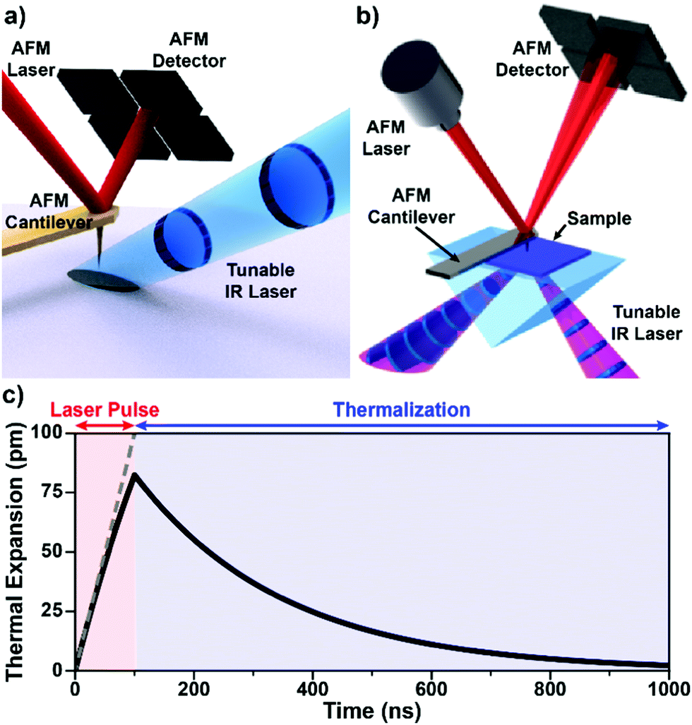 | ||
| Fig. 1 (a) Schematic illustrating AFM-IR with top-down illumination. A pulsed IR laser is focused on the sample around the AFM probe tip, which transduces the sample photothermal expansion by deflecting a visible-light laser off its backside to a position-sensitive detector. Gold-coated cantilevers limit the background light absorption by the probe. Adapted from M. Tuteja et al., Analyst, 2018, 143, 3808–3813. with permission from the Royal Society of Chemistry.18 (b) Schematic illustrating AFM-IR with total internal reflection (bottom) illumination, which minimizes background light absorption thanks to the evanescent field excitation, but requires sample preparation on an optical prism (typically ZnSe or ZnS). Adapted with permission from A. M. Katzenmeyer et al., Anal. Chem., 2015, 87, 3154–3159. Copyright (2015) American Chemical Society.8 (c) Simulated sample photothermal expansion (solid black line) accounting for heat diffusion during (red) and after (blue) the absorption of an incident laser pulse. The sample contracts (thermalizes) exponentially with a characteristic time that depends on its thermal properties and thickness according to eqn (3). The dashed gray line represents a hypothetical linear expansion that neglects heat diffusion during a constant-power laser pulse. | ||
In addition to AFM capabilities, AFM-IR requires a pulsed, wavelength-tunable, spectrally narrow laser source7,8,26 together with optics for beam steering, focusing, and polarization control. No IR sensitive detector is needed since the position-sensitive detector captures the mechanical deflection of the probe due to both the (slowly varying) sample topography and the (rapidly varying) IR-induced photothermal signals (see below). The sample can be illuminated either from the top (Fig. 1a) or from below via total internal reflection (Fig. 1b) by focusing the IR laser beam to a ≈ 40 μm spot around the probe tip. The most important aspect pertaining to the sample illumination in AFM-IR is the alignment of the IR laser beam with respect to the AFM tip for all wavelengths, which typically is achieved by means of motorized beam steering routines and is essential for obtaining high-quality spectra (see Section 4 for details). While AFM topographic imaging can be achieved by scanning the tip or the sample, AFM-IR setups always scan the sample to maintain the tip-laser alignment.
The bottom illumination approach was developed first27 and has the advantage of limiting background absorption from liquid environments24,28 and from the AFM probe itself, thereby enabling the use of uncoated tips14,24,25 or tips that otherwise absorb IR light.29 Uncoated tips are typically sharper and can be used to measure plasmonic nanostructures without altering their near-fields.30 However, the bottom illumination scheme typically requires thin (< 1 μm) samples and complex sample preparations on an optically transparent prism.17,23 By contrast, top illumination is currently the more commonly used illumination geometry as it enables simpler sample preparations on a wider variety of substrates. However, to limit IR absorption by the probe, which produces an unwanted background signal,7,31,32 the top illumination scheme requires metal-coated probes. The coating (typically gold) of the tip and/or of the substrate provides a mild (≈ 1.5 × to ≈ 10 ×), polarization dependent, near-field enhancement that increases the measurement sensitivity depending on the illumination conditions and substrate characteristics.33 This enhancement is important for measuring thin (< 20 nm) samples7,9,32 but generally is not critical for most AFM-IR measurements. Light polarization effects on the tip and sample in AFM-IR have been thoroughly discussed in a previous review10 and will only be mentioned briefly. Although all the lasers used for AFM-IR emit linearly polarized light, the polarization of light at the sample is not always known or well-controlled depending on the instrument configuration. For example, earlier setups14 used wire grid polarizers on a rotation stage to attenuate the laser power, which had the additional effect of rotating the direction of the linear polarization at the sample. Newer setups use polarization-preserving attenuation stages and sometime have an additional polarization rotation stage to switch between s and p light polarizations. Custom polarization optics have also been used to illuminate the sample with circularly polarized light.34 In addition to the tip enhancement,35 light polarization can be leveraged to determine the molecular orientation,36,37 and structure35 of the sample and to efficiently excite or launch optical modes (e.g., plasmons and polaritons).23,30,38,39 More details on sample illumination schemes can be found in a previous review.5
The availability of wavelength tunable lasers is a critical enabling factor for AFM-IR experiments.7,8,26 Three types of commercially available, narrow linewidth, wavelength-tunable IR lasers have been employed for AFM-IR measurements, either based on non-linear optics (optical parametric oscillators, OPOs,8,26,40 and difference frequency generation, DFG26) or based on semiconductor technology (quantum cascade lasers, QCL).7 External cavity OPO/DFG systems were instrumental for AFM-IR initial adoption and are characterized by high pulse energies (> 1 μJ), a low repetition rate (1 kHz), fixed pulse lengths (typically 10 ns), moderate linewidths (≈ 8 cm−1), slow wavelength-tuning (typically ≈ 3 cm−1 s−1), and a very broad spectral range, up to 0.5 μm to 16 μm (20000 cm−1 to 625 cm−1).8 External cavity QCL are currently the most commonly used lasers in AFM-IR and are characterized by low pulse energies (typically < 0.1 μJ), tunable repetition rate (1 kHz to 3 MHz), tunable pulse lengths (typically 40 ns to 500 ns), fast wavelength tuning (> 100 cm−1 s−1), and their spectral ranges have been recently expanded from 3.3 μm to 13.4 μm (3030 cm−1 to 750 cm−1). Commercially available external cavity QCL arrays, however, typically combine four chips to achieve tuning ranges of about 1000 cm−1. Intra-cavity OPOs40 are characterized by moderate pulse energies (≈ 0.5 μJ), moderately tunable repetition rates (150 kHz to 350 kHz), fixed pulsed lengths (typically 10 ns), fast wavelength tuning (> 100 cm−1 s−1), and a tuning range from around 2.5 μm to 3.7 μm (4000 cm−1 to 2700 cm−1) that is somewhat complementary to QCLs.
The implications of the AFM-IR energy transduction chain in determining the signal amplitude, spatial resolution, and probed depth are discussed in detail in the following section. Briefly, the optical energy of an incident laser pulse is absorbed by the sample proportionally to its optical absorption coefficient and converted photothermally into heat, leading to the thermal expansion of the sample. The duration of the expansion phase is set by the laser pulse length (typically 10 ns to 500 ns). After the pulse, the sample contracts with a characteristic thermalization time ranging from < 0.1 ns to a few μs (Fig. 1c) depending on the sample thickness, thermal conductivity, and other thermal properties25,29,64 (see detailed discussion in Section 3). Considering the typically small temperature rise in the sample (< 10 K with OPOs; < 1 K with QCLs), thermal expansion coefficients (≈ 10−6 to ≈ 10−4), and the small thicknesses of AFM-IR samples (< 500 nm), the resulting photothermal expansion is typically < 1 nm and often just few picometers.25,64 The rapid sample thermal expansion changes the instantaneous equilibrium position of the cantilever and imparts speed to it. Using custom-made opto-mechanical AFM probes that provide high sensitivities (≈ 3 fm Hz−0.5) over a wide bandwidth (≈ 25 MHz), i.e., even off resonance, our group was able to measure the time-domain sample thermal expansion dynamics directly, illustrated in Fig. 1c.25 Conventional AFM probes provides sufficient sensitivity only in narrow frequency bands centered around the cantilever mechanical resonances (see Fig. 2) and, therefore, are unable to capture the sample thermal expansion dynamics in the time domain. However, the fast thermal expansion of the sample imparts speed and “kicks” the cantilever into oscillation, akin to a struck tuning fork. The AFM detector captures the amplitudes at the cantilever resonant mechanical frequencies (see Fig. 2) that follow the impulsive excitation of the AFM cantilever, completing the AFM-IR transduction. Importantly, the amplitudes of the cantilever oscillations are proportional to the absorption coefficient of the sample under the AFM tip.13–15,25,41 Also, since the sample is scanned slowly (< 1 Hz) and the cantilever frequencies are > 100 kHz, there is no cross-talk between topographic and photothermal signals. Spectra are obtained by sweeping the laser wavelength while maintaining the AFM tip position stationary. Conversely, AFM-IR maps are obtained by scanning the sample while illuminating it with a fixed wavelength. Hyperspectral images (spectra obtained on a dense grid of points) are also possible but uncommon due to the long acquisition times currently required.42
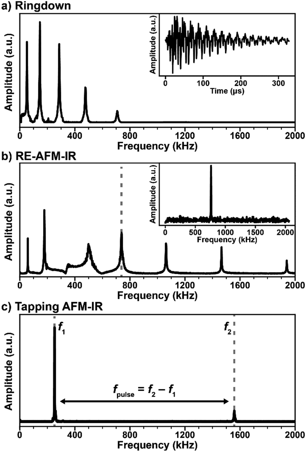 | ||
| Fig. 2 (a) Representative frequency domain (main panel) and time domain (inset) signals for the AFM-IR ringdown excitation scheme (1 kHz, off-resonance laser pulses). The cantilever bending modes are excited with intensities proportional to the absorbed energy of the sample, inversely proportional to the mode stiffness, and with an efficiency that depends on the power profile of the excitation pulse. (b) Main panel: representative RE-AFM-IR signal intensities obtained by sweeping the laser repetition rate over a range containing the first 7 cantilever resonance modes. Whenever the laser repetition rate matches a cantilever resonance frequency the signal is amplified by ≈ Q/(2π). Inset: frequency domain RE-AFM-IR signal intensity when pulsing the laser at the ≈ 738 kHz cantilever resonance frequency. (c) Representative tapping mode resonances (f1 ≈ 252 kHz, f2 ≈ 1558 kHz). In tapping mode AFM-IR, the cantilever typically is driven at frequency f2 while the laser is pulsed at fpulse = f2 − f1 and the signal is demodulated at f1. The opposite scheme (tapping at f1 and demodulating the signal at f2) is also possible. | ||
The simplest AFM-IR excitation scheme leverages a soft contact mode cantilever and wavelength-tunable lasers with a pulse repetition rate (1 kHz) that is much lower than the mechanical resonance modes of the AFM cantilever (Fig. 2a). This method is referred as “ringdown” since the fast sample photothermal expansion that follows light absorption excites all cantilever modes, off resonance, with amplitudes proportional to the sample absorption coefficient and inversely proportional to the cantilever mode stiffness, which increases with frequency. The cantilever oscillations dissipate (ringdown) on a time scale of ≈ 500 μs (see Fig. 2a, inset), which is much longer than the sample thermalization time.25,64 Often, a narrow bandwidth (≈ 50 kHz) band-pass filter centered around one of the cantilever resonances is used to increase the signal-to-noise ratio. A ringdown spectrum is obtained by plotting the amplitude of a selected cantilever resonance in the frequency domain, or the maximum peak-to-peak amplitude of the time-domain signal as a function of the laser wavelength. Ringdown experiments typically leverage OPO lasers with ≈ 10 ns pulse lengths,8 but pulses as short as ≈ 0.1 ns (DFG)26 or as long as ≈ 500 ns (QCL)43 have been used. Notably, the availability of suitable (1 kHz) OPO laser sources continuously tunable from 500 nm to 2300 nm have extended AFM-IR experiments in the visible and near-IR ranges enabling measurements of the bandgap,16,17 optically active defects,17 and chemical composition with a wavelength-independent spatial resolution as high as 20 nm.8 Although monolayer sensitivity has been achieved for ringdown AFM-IR measurements using nanoscale opto-mechanical probes,25 measuring samples thinner than 50 nm with conventional AFM probes is challenging with this modality.14 Since ringdown AFM-IR has been in reviewed in great detail previously,4–6 here we will discuss only insightful ringdown experiments that elucidate the AFM-IR signal transduction.
The introduction of the resonant excitation scheme7 has been an important breakthrough in AFM-IR technology, enabled by the availability of QCLs with tunable wavelengths, pulse lengths, and repetition rates (up to a 3 MHz). In RE-AFM-IR, the resonant excitation is attained by matching the laser repetition rate to one of the cantilever contact resonance frequencies (Fig. 2b). Akin to synchronously (in phase) pushing a child on a swing, the high-frequency pulse train (and resulting thermal expansion of the sample) pushes the cantilever and amplifies its oscillations at the selected mechanical resonance to larger and larger amplitudes, limited only by dissipation forces within the cantilever, environment, and sample. The AFM-IR signal boost or gain from resonant excitation is g ≈ Q/(2π), where Q is the quality factor of the cantilever mode, defined as the resonance amplitude over its full width at half-maximum. Given the typical Q-factors (25 to 250) of contact mode cantilevers in air, the signal amplification is ≈ 5 × to ≈ 40 × with respect to the ringdown mode. In practice, the RE-AFM-IR signal-to-noise ratio improvement is < g and the improvement in measurement throughput is < g2 due to variations of the cantilever resonance frequencies resulting from spatially varying sample elastic moduli and fluctuations of the cantilever responsivity with time.44 In fact, RE-AFM-IR became the dominant AFM-IR modality only after the introduction of a phase-locked loop (PLL) that maintains the match between the laser repetition rate and the phase of the cantilever resonance, thereby decreasing the measurement variability.9,44 These aspects will be discussed in detail in Section 4. The increased sensitivity of RE-AFM-IR enables routine measurement of samples thinner than 20 nm,9,32 down to monolayers, in air7 and even enables measurements in liquid environments.24,28 Another major benefit from the resonance-enhanced approach is provided by the wavelength tuning of QCL lasers that enables acquisition of ≈ 1000 cm−1 wide RE-AFM-IR spectra in ≈ 10 s (typically), or less than 1 s, in principle. A RE-AFM spectrum is obtained by plotting the amplitude of a selected cantilever resonance in the frequency domain as a function of the laser wavelength.
The implementation of the AFM-IR measurement in tapping mode is another recent advance that also necessitates a laser with both tunable wavelength and repetition rate. In tapping mode AFM-IR, oscillations in the cantilever are driven at one of its resonance frequencies (e.g., f2 ≈ 1550 kHz in Fig. 2c) while the laser is pulsed at the difference frequency fpulse = f2 − f1 (e.g., ≈ 1300 kHz) with another resonance mode. Using this type of heterodyne (frequency mixing) detection scheme, the cantilever is resonantly excited (e.g., at f1 ≈ 250 kHz) due to the non-linear tip–sample interactions modulated at the oscillation driving frequency (at f2) and sample photothermal expansion (at fpulse).5,11 The main benefits of tapping mode AFM-IR typically are improved (< 10 nm) spatial resolution and the ability to characterize samples that are difficult to map in contact mode, such as very soft,9,19 sticky,18 easily displaced samples,19,39 or samples characterized by abrupt topographic variations.3,12 The recent commercial implementation of a PLL for tapping mode AFM-IR measurements has increased the measurement stability, however, it has not made the RE-AFM-IR method obsolete as the latter can, in many cases, provide higher signal-to-noise ratios. Tapping mode AFM-IR will be discussed in detail in Section 5. The recently introduced variants peak force tapping and surface sensitivity AFM-IR modes will be briefly presented in Section 6.
3. AFM-IR signal transduction: lessons learned from notable experiments and theory
The striking similarity of AFM-IR spectra to IR transmission spectra has driven its adoption within the analytical chemistry community and beyond. However, despite this similarity, detailed understanding of the sample thermal expansion and AFM cantilever dynamics is critical for interpreting AFM-IR measurements quantitatively and near the resolution limit of the technique.As described previously, the measured AFM-IR signal originates from the absorption of optical energy by the sample that is then transduced through a sequence of steps: local heating, local thermal expansion, probe tip motion, and finally into a cantilever deflection signal at the position-sensitive detector. In the theory developed by Dazzi et al., the overall AFM-IR signal intensity is factored according to each step within this signal transduction chain.13 It is convenient to rewrite Dazzi's original expression in the form of Ramer et al.,15
| SAFM-IR ∝ HAFMHexpHthermHopt(λ)Iinc(λ) | (1) |
![[n with combining circumflex]](https://www.rsc.org/images/entities/i_char_006e_0302.gif) (λ) = n(λ) + iκ(λ) (λ) = n(λ) + iκ(λ) | (2) |
Ramer et al.15 used thin film optics to calculate the sample optical absorption, Hopt(λ), as a function of the sample thickness, absorption coefficient, and light polarization in the case of TIR illumination. Such analysis permits understanding the effect of these parameters on the AFM-IR signal linearity, peak shifts, peak intensity ratios, and sample stratification, as well as to derive guidelines for optimal sample preparation and data analysis. Ramer's work extended Dazzi's original AFM-IR theory13 to the case of strong absorbers, which typically cause strong IR spectral distortions in the far-field due to the influence of the real part of the refractive index on the spectra. The authors found that absorption is most linear for uniformly thin (< 500 nm), vertically homogeneous samples. Deviations from linearity are linked to the optical properties of thin films, which also apply to conventional IR spectroscopy methods and are not intrinsic to AFM-IR measurements. Note that pixel-to-pixel variations in the sample thickness are common in AFM-IR measurements, which should be accounted for in quantitative analyses. The linearity of the AFM-IR signal was verified for bottom illumination with ringdown excitation14 and for top illumination with resonance enhanced excitation; see Fig. 3.22 A demonstration of the proportionality between the AFM-IR signal and the absorption coefficient was recently reported for tapping mode AFM-IR and for the surface-sensitivity mode, which exploit non-linear tip–sample interactions to limit the probed depths to ≈ 50 nm and ≈ 25 nm, respectively.11
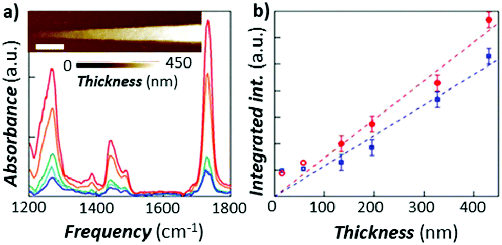 | ||
| Fig. 3 (a) RE-AFM-IR spectra obtained with a gold-coated cantilever on a PMMA wedge for thicknesses of 15 nm (blue), 58 nm (light blue), 134 nm (green), 327 nm (orange), and 430 nm (red). Inset: topography of PMMA wedge with variable thickness fabricated on a gold-coated silicon substrate; scale bar is 1 μm. (b) integrated RE-AFM-IR band intensity at 1250 cm−1 (blue circles) and at 1730 cm−1 (red squares) as a function of the PMMA thickness. Deviation from linearity for thicknesses below 50 nm is likely due to the plasmonic field enhancement between the tip and substrate. Adapted from L. Baldassarre et al., Nanotechnology, 2016, 27, 075101. DOI: https://doi.org/0.1088/0957-4484/27/7/075101. © IOP Publishing. Reproduced with permission. All rights reserved.22 | ||
The most important result from Ramer et al.15 is that the AFM-IR peak shape variations and spectral shifts are small (< 5 cm−1, see Fig. 4) even for conditions that cause extreme spectral distortions in macroscale measurements, e.g., TIR illumination, thick sample (> 1200 nm), and very strong absorption coefficient.15 This notable characteristic is intrinsically related to the photothermal effect13 that directly links the temperature increase in the sample to the sample absorption coefficient, and makes chemical identification of unknown species with AFM-IR reliable. In other words, the real part of the refractive index, n(λ), affects only the local light distribution in the sample (only marginally affecting the relative AFM-IR intensities) while the direct proportionality between the imaginary component, κ(λ), and AFM-IR signal determines the spectral shape.
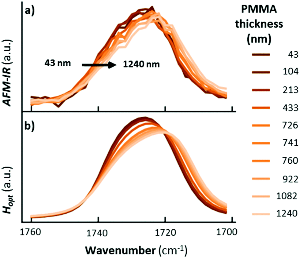 | ||
| Fig. 4 (a) Measured and (b) calculated AFM-IR spectra obtained with TIR illumination and p-polarized light for the strong carbonyl absorption for a PMMA wedge of variable thickness deposited on a ZnSe substrate. Adapted with permission from G. Ramer et al., Anal. Chem., 2017, 89, 13524–13531. Copyright (2017) American Chemical Society.15 | ||
In the mid-IR, the absorbed energy by the sample is directly converted into vibrational energy. This vibrational energy of a localized mode, for instance a carboxylate group vibrating at high frequency with low amplitude, is quickly redistributed to high-amplitude, low-frequency collective modes and subsequently transferred to phonons on sub-nanosecond time scales; see Katzenmeyer et al.8 and references therein. The amplitude of the sample thermal dynamics (Htherm),13 depicted in Fig. 1c, depends on the absorbed energy in the sample as determined by Hopt(λ), while its temporal evolution depends on the laser pulse length and on the sample thermal properties (see below).15 Therefore, the maximum temperature rise of the sample is directly related to the sample absorption coefficient.
Pioneering work by Hammiche et al.45 attempted to capture the temperature rise in the sample by combining Fourier transform IR spectroscopy and scanning thermal microscopy (SThM) using (relatively large) temperature-sensitive Wollaston wire probes. However, such attempts have been hindered by contrasting needs to improve the sensitivity of the measurement (requiring larger probes)46 and its lateral resolution (requiring smaller probes), optimistically estimated as ≈ 5 μm.47 Using nanofabricated, temperature-sensitive SThM probes in a AFM-IR setup, our group was able to capture time domain signals proportional to the temperature rise of the sample due to light absorption (see Fig. 5a). The magnitude of the thermal signal yields chemical maps (Fig. 5b–d) down to ≈ 70 nm spatial resolution while the sample thermalization time (τs) can be used to derive the local sample thermal conductivity.29 Neglecting the interfacial thermal conductance between the sample and substrate, τs depends on the sample specific heat capacity (cp), density (ρ), thermal conductivity (η), and thickness (z):25,64
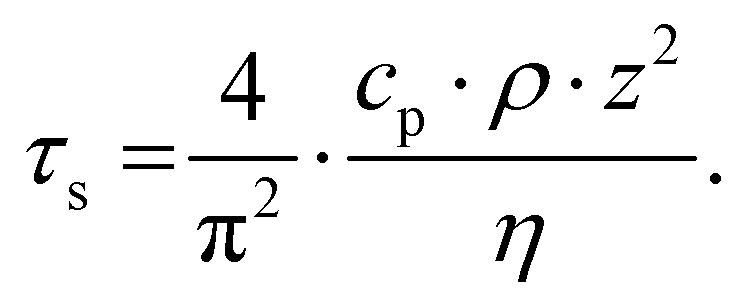 | (3) |
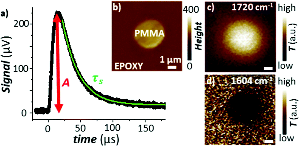 | ||
| Fig. 5 (a) Time-domain signal measured using a nanofabricated SThM probe in an AFM-IR setup with TIR illumination. The signal is measured via a change of the probe's electrical resistance and is proportional to the temperature rise in the sample due to the absorption of a light pulse. The green line is an exponential fit to the signal decay according to eqn (3). (b) Topography map of a PMMA particle within an epoxy matrix. Temperature maps obtained by illuminating the sample at (c) 1720 cm−1 (PMMA) and at (d) 1604 cm−1 (epoxy). Pixel size is 100 nm × 100 nm. Adapted from A. M. Katzenmeyer et al., Nanoscale, 2015, 7, 17637–17641 with permission from the Royal Society of Chemistry.29 | ||
However, the spatial resolution of this approach29 is significantly worse (see Fig. 5d) than for AFM-IR. Additionally, the thermal conductivity of the sample can be obtained only if its thermalization time is longer than the thermalization of the probe (≈ 15 μs), i.e., only for thick (> 1000 nm) samples with low thermal conductivities (η < 0.4 W m−1 K−1).29
The amplitude of the sample thermal expansion dynamics, Hexp ∼ α·Htherm·Hopt(λ),13 depends on the sample thermal expansion coefficient (α). However, sensing fast sample dynamics, such as the light-induced thermal expansion of the sample (Fig. 1c), with AFM is challenging. Miniaturization of the probe enables faster reaction times due to the higher mechanical resonant frequencies, but those probes are typically less sensitive (i.e., they deflect by a smaller amount since they are mechanically stiffer). Additionally, optical far-field detection of cantilever deflections becomes impractical for cantilevers with cross-sections smaller than the optical diffraction limit of the AFM detection laser. Recently, our group made a radical advance in measuring the sample thermal expansion dynamics using an optomechanical probe consisting of a nanosized cantilever, a disk resonator, and a waveguide all made of silicon (Fig. 6b).
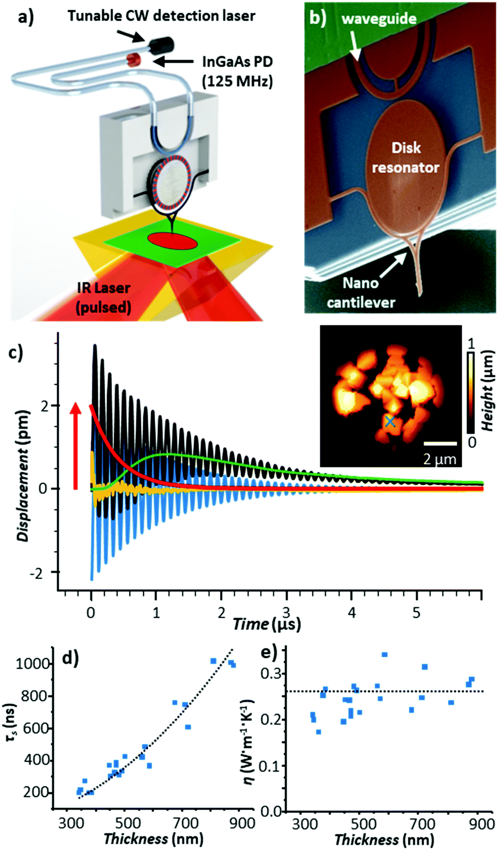 | ||
| Fig. 6 (a) Schematic of the optomechanical AFM-IR setup. A tunable, continuous wave (CW) detection laser and photodetector (PD) are fiber-coupled to an on-chip waveguide that excites, via near-field coupling, a whispering gallery optical resonance in a silicon disk. The resonance frequency is modulated, also via near-field coupling, by the movement of a nanoscale probe. The low noise and large bandwidth of this setup enables measurements of the sample thermalization with 10 ns resolution. (b) Colorized scanning electron micrograph of the optomechanical transducer. (c) Time-domain AFM-IR signal at 1388 cm−1 (black) obtained on a 560 nm thick HKUST-1 metal organic framework microcrystal (indicated by × in AFM topography inset). In addition to the cantilever ringdown (blue) and background probe heating (green), the probe's instantaneous equilibrium position (red) follows the dynamic sample thermal expansion, with the residual of the fit shown in yellow. (d) Thermalization time (τ) and (e) thermal conductivity of HKUST-1 microcrystals as a function of thickness; the black line is given by eqn (3). Adapted with permission from J. Chae et al., Nano Lett., 2017, 17, 5587–5594, copyright (2017), American Chemical Society.25 | ||
Both the cantilever and the waveguide are near-field coupled to the disk. In place of the common far-field beam-bounce AFM detection scheme, the optomechanical setup leverages a continuous wave (CW), wavelength-tunable detection laser and a large bandwidth (125 MHz) photodetector that are fiber-coupled to the waveguide (Fig. 6a). Variations in the cantilever position (e.g., due to photothermal excitation by the sample) shift the disk whispering gallery optical resonance frequencies and the transmitted signal intensity through the fiber proportional to the displacement. This measurement scheme results in ultralow detection noise (≈3 fm Hz−0.5) over a wide bandwidth (≈ 25 MHz), enabling high-precision time-domain AFM-IR measurements of the sample thermal expansion (red trace in Fig. 6c) with ≈ 10 ns resolution (i.e., ≈ 1500 × faster than the temperature-sensitive probes in Fig. 5). For example, by analyzing the sample thermalization dynamics, we were able to obtain the thermal conductivity of metal–organic framework single microcrystals with nanoscale resolution (see Fig. 6c and e).25 Very recently, further improvements to this time-domain AFM-IR detection scheme have enabled our group to map thermal conductivity and interfacial thermal conductance with nanoscale resolution and high throughput (20 ms/pixel).64 Furthermore, those probes enable AFM-IR ringdown spectral measurements of molecular monolayers,25 thanks to 50 × improved sensitivities compared to conventional AFM probes.
The amplitudes of cantilever oscillation modes (HAFM) are inversely proportional to the modal stiffnesses and are directly proportional to the sample thermal expansion (Hexp).13,48 As discussed below, the link between the sample thermal expansion and the cantilever oscillation dynamics crucially determines the AFM-IR signal amplitude, signal-to-noise ratio, and spatial resolution. This linkage, however, has received little attention because of the challenges of measuring thermal expansion dynamics experimentally and in converting the sample thermal expansion to short laser pulses into cantilever dynamics, theoretically.49 For example, Morozovska et al. calculated the full dynamic thermoelastic response (photothermal expansion) of a sample composed of PMMA and epoxy separated by a sharp boundary, excited by sinusoidally modulated light at frequencies between 1 kHz and 1 MHz. While the sinusoidal modulation is used in AFM-IR measurements with synchrotron light sources,50 the cantilever response to high frequency sinusoidal modulation is not equivalent to its response to short laser pulses of the same frequency.49 Therefore, the experimentally demonstrated proportionality between the thermal expansion of the sample after the laser pulse (red trace in Fig. 6c) and the maximum amplitude of the cantilever's induced ringdown (black and blue traces in Fig. 6c), i.e., the AFM-IR signal measured by conventional cantilevers, crucially validates Dazzi's AFM-IR signal transduction theory.
For both ringdown and resonance-enhanced techniques, each of the cantilever resonance modes (Fig. 2a and b) could be used for AFM-IR experiments. Since the cantilever oscillations are excited in reaction to the fast sample expansion, rather than a gentler sinusoidal excitation, AFM-IR spatial resolution is much better than the thermal diffusion limit.51 In other words, the high-frequency components of the excitation and the resulting thermal expansion provide a broad excitation spectrum even at relatively low repetition rates. Therefore the AFM-IR spatial resolution is not a strong function of the laser repetition rate (fpulse), although it typically improves using higher resonance cantilever frequencies51 due to the non-negligible effect of thermal diffusion on the expansion of surrounding non-absorbing regions. However, since cantilevers modes with higher resonance frequencies have higher modal stiffnesses, they are also typically less sensitive to the sample photothermal expansion and a compromise must be found. Typically, a sharp, tall (high-Q) cantilever resonance peak is preferred.
AFM-IR enables spatial mapping of chemical heterogeneities and optical anisotropies at the nanoscale. As previously mentioned, the direct proportionality between Hopt(λ) and κ(λ), produces AFM-IR spectra that resemble conventional IR spectra with high fidelity. Optical (chemical) anisotropies can be resolved at the nanoscale using polarized light, as discussed in an earlier review10 and in the references therein. However, the AFM-IR signal amplitude is also affected by the scaling factor HAFMHexpHtherm that depends on the local thermo-mechanical properties of the sample and the local tip–sample mechanical interactions, making quantification challenging. For stable measurement conditions (i.e., if the tip–sample interactions are time invariant), to first approximation, spectral ratios are often used for in semi-quantitative analyses since the scaling factor is independent of wavelength.52
In the remainder of this section, we will discuss instructive, though typically rare, examples where the variability of the signal scaling factor across the sample has a significant effect on the AFM-IR spectral intensities. An extreme case was reported by Barlow et al.52 measuring ≈ 200 nm thick Pseudomonas protegens Pf-5 bacteria on a very soft and highly damping polyurethane film (≈ 300 nm thick); see Fig. 7. In that work, AFM-IR (ringdown) spectra and chemical maps on the bacteria showed IR absorption peaks characteristic of both the polyurethane film and of the bacteria, as expected since ringdown AFM-IR is not a surface-selective method and can probe the sample to depths in excess of 1 μm.14 However, the AFM-IR signal intensities of polyurethane's characteristics peaks (e.g., 1732 cm−1, Fig. 7b) were stronger when the tip was positioned on the bacteria rather than directly on the polymer. In this case, the mechanical properties of the polyurethane (low modulus, high damping) resulted in a relatively inefficient cantilever excitation in comparison to the bacteria (higher modulus, less damping, more efficient signal transduction). Since the mechanical properties of the sample do not depend on the incident wavelength, ratios of the AFM-IR signal9,52 can be used to normalize the measured intensities to compensate for such mechanical effects (see Fig. 7c). Kenkel et al.48 showed that, between ≈ 250 kHz to ≈ 1000 kHz, the mechanical scaling factor (HAFM) in AFM-IR experiments is reasonably similar to the cantilever response to a piezo actuator shaking the sample. Therefore, the local variability of HAFM can be compensated through pixel-by-pixel division of the AFM-IR intensity by the cantilever response to the sample piezo shaker at the same frequency (Fig. 8). This pixel-by-pixel responsivity correction works most reliably for frequencies at which the mechanical response variability is minimized (i.e., off resonance) and typically is less prone to drift-induced artifacts than for the sequential imaging required to obtain image ratios.48
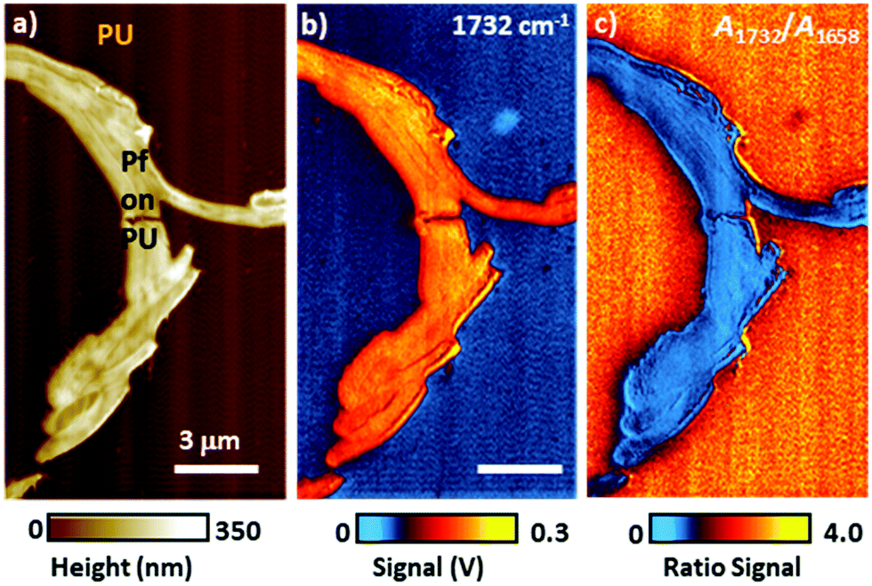 | ||
| Fig. 7 (a) Topography image of a Pseudomonas protegens Pf-5 bacteria cluster (Pf) on a 300 nm thick polyurethane (PU) layer. (b) AFM-IR map at 1732 cm−1 corresponding to PU carbonyl absorption. Although a larger photothermal expansion is expected on the PU region, the AFM-IR signal is stronger when the AFM tip is in contact with the stiffer Pf than on the softer and highly damping PU. (c) Ratio map obtained by dividing the AFM-IR intensity map of PU carbonyl (1732 cm−1) by the intensity map of Pf amide I (1658 cm−1), showing the expected stronger PU absorption around (not on) the Pf cluster. Image ratios, in first approximation, normalize the influence of the sample's mechanical properties on the AFM-IR signal. Adapted from D. E. Barlow et al., Analyst, 2016, 141, 4848–4854 with permission from the Royal Society of Chemistry.52 | ||
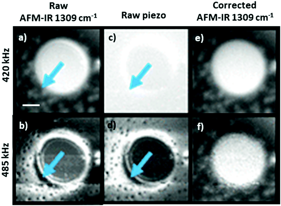 | ||
| Fig. 8 As-recorded AFM-IR images of a polybutadiene–polystyene sample at 1309 cm−1 (polybutadiene absorption), obtained by pulsing the laser off resonance at (a) 420 kHz and at (b) 485 kHz. Corresponding mechanical excitation images (no IR illumination) obtained by shaking the sample at (c) 420 kHz and at (d) 485 kHz. Responsivity corrected AFM-IR images showing the ratio of the as-recorded AFM-IR and mechanical excitation images at (e) 420 kHz and at (f) 485 kHz. Arrows indicate regions with high responsivity variation due to local variation of the sample mechanical properties. Scale bar is 1 μm. Adapted with permission from S. Kenkel et al., Anal. Chem., 2018, 90, 8845–8855. DOI: https://doi.org/10.1021/acs.analchem.8b00823 Copyright (2018) American Chemical Society.48 Further permissions related to the excerpted material should be directed to the American Chemical Society. | ||
Although the scaling factors of AFM-IR spectra are unknown, they are constant at a single location. Since the penetration depth of IR light depends on light polarization, quantitative AFM-IR analyses could be obtained by measuring just two spectra with different light polarizations at each location and by inverting the AFM-IR signal via a numeric Kramers–Kronig transformation.15 Details of this generally applicable theoretical approach are beyond the scope of this tutorial review but are available in a previous publication.15
While nanoscale mechanical heterogeneities in the sample can confound or accentuate chemical contrast in AFM-IR measurements, nanoscale mechanical anisotropy reveals additional details about the sample's structure. For example, AFM-IR experiments by Strelcov et al. detected ferroelastic domains in polycrystalline CH3NH3PbI3 perovskite films53 which are of great interest for photovoltaic and other optoelectronic applications. As shown in Fig. 9, the AFM-IR (PTIR) images and spectra of vibrational (1468 cm−1, methyl-ammonium CH3 asymmetric deformation) and electronic (13250 cm−1, 1.64 eV) transitions reveal nanoscale domains within perovskite grains not evident in the sample topography, which differ only in the intensity of the AFM-IR signal. The domains in the AFM-IR absorption images were shown to be invariant with respect to light polarization and applied electric field, and are the result of anisotropic thermal expansion of the material in differently oriented ferroelastic twin domains.53
 | ||
| Fig. 9 (a) AFM topography of a CH3NH3PbI3 perovskite film and the corresponding AFM-IR (PTIR) images of (b) CH3 asymmetric deformation of the methylammonium ion (1468 cm−1) and (c) electronic transition above the bandgap (13250 cm−1, 1.64 eV). (d) Representative electronic (left) and vibrational (right) absorption spectra obtained from contiguous ferroelastic domains at the color-coded locations in panels a–c. Adapted with minor visual changes with permission from E. Strelcov et al., Sci. Adv., 2017, 3, e1602165. © The Authors, some rights reserved; exclusive licensee AAAS. Distributed under a CC-BY-NC 4.0 License (https://creativecommons.org/licenses/by-nc/4.0/).53 | ||
4. Resonance-enhanced AFM-IR
4.1 RE-AFM-IR tutorial
To ensure accurate measurements, AFM-IR users must set various instrument parameters based on both the AFM mode of operation (contact, tapping, peak force, etc.) and on the AFM-IR excitation mode (ringdown, resonance enhanced, etc.). In this section, we provide guidance to set up contact mode RE-AFM-IR measurements with top-down illumination (Fig. 1a), which is the most common configuration in commercial instruments.Conventional AFM scanning parameters, including the contact force set point, scan rate, and feedback gains should be tuned to produce artifact-free topography maps of the sample surface. The values of these parameters depend on the sample and the probe used in the measurements; however, they can be optimized using similar procedures as in conventional AFM imaging. One common practice adjusts the scanning parameters to minimize the discrepancy between the topography profiles measured in forward and backward fast-scan directions. Reliable tracking of the sample topography by the probe tip is a prerequisite for accurate AFM-IR measurements.
All AFM-IR measurements require a pulsed, wavelength-tunable IR laser focused to the sample surface and centered (aligned) on the probe tip, which is critical to obtain high-quality spectra and images. Typically, commercial instruments are aligned during installation using a well-known reference sample and iterating an AFM-IR signal maximization procedure that scans the laser spot position on the sample using an adjustable focusing element and motorized beam steering mirrors. Once set, the focusing element does not typically require further adjustment. However, to maximize signal strength, the AFM-IR user should complete a simpler beam steering routine to compensate for any shifts due to temperature fluctuations affecting the laser optics and beam path, and to compensate for unavoidable changes in the position of the tip after replacing AFM cantilevers. This optimization procedure should be repeated at least once within the spectral range of each QCL stage used in the measurement at wavelengths near strong absorption resonances in the sample. Optimizing the beam position more than once per stage provides a useful check on the process and enables linear interpolation within each QCL stage for more accurate beam alignments. Additionally, large shifts in the mirror positions for two wavelengths within the same QCL stage can be a tell-tale sign of suboptimal alignment. This alignment procedure can be performed directly on the sample if sufficient details are known about its composition and morphology. For uncharacterized samples, without a known absorption spectrum, a separately measured far-field IR spectrum can provide initial guidance. Alternatively, this routine can be performed first on a well-characterized “reference sample” and later refined on the new sample.
In RE-AFM-IR, the laser pulse rate must match a cantilever contact resonance frequency to obtain resonant amplification (≈ Q/2π) of the AFM-IR signal. To accomplish this frequency matching, first the tip is positioned over a feature that is expected to exhibit strong IR absorption. The AFM-IR signal is monitored while the laser pulse rate is swept over a wide range intended to span several cantilever resonance modes (see Fig. 2b). Compared to off-resonance conditions, whenever the laser pulse rate is near a cantilever resonance frequency, the measured AFM-IR signal is strongly enhanced; see peaks near 60 kHz, 180 kHz, 750 kHz, etc. in Fig. 2b. Each of the cantilever resonances modes could be used for the AFM-IR experiment. As mentioned in Section 3, the mode choice affects the spatial resolution, signal-to-noise ratio, and the throughput of the measurements. Typically the spatial resolution improves and the signal-to-noise ratio decreases when using higher frequency cantilever modes51 due to the weak, but non-negligible, effects of thermal diffusion on the expansion of the surrounding non-absorbing regions and due to the larger modal stiffnesses of higher frequency modes. Typically, a sharp, tall (high-Q) cantilever resonance peak is preferred.
The cantilever contact resonance frequencies and Q-factors depend on the local stiffness and damping of the sample, respectively. Therefore, the resonance conditions can change during an experiment, for example, due to heterogeneity in the sample's mechanical properties or due to temperature-induced softening; the latter is easily avoided by reducing the incident laser power. Consequently, to ensure stability and reproducibility of the measurement, a PLL is used to maintain the laser pulse rate at the cantilever frequency automatically during the measurement.9 We also note that the PLL only compensates for frequency shifts due to position-dependent heterogeneities in the sample stiffness, not for changes in the cantilever Q resulting from heterogeneities in the sample damping.
The laser power should be tuned to produce a strong AFM-IR signal that does not excessively heat the sample. Overheating can cause irreversible thermal damage to the sample or softening of the sample that, in turn, downshifts the cantilever frequency and reduces the AFM cantilever mechanical transduction efficiency.9,52
Alongside the AFM-IR signal amplitude, several additional data channels, such as the sample topography and the laser pulse frequency (locked to the cantilever resonance frequency shifts), can be recorded simultaneously. These additional data channels give context to the AFM-IR measurement and aid the assessment of the measured data quality. We note that since the incident IR light can penetrate up to a few μm in some samples, regions of high signal contrast evident in AFM-IR absorption images may not necessarily correlate with features evident in the surface topography since they can result from absorption by materials located within9 or beneath the sample.54 Changes in the contact resonance frequency can be associated either with changes in the inherent stiffness of the top (≈ 25 nm) sample layer, in the case of heterogeneous samples, or less commonly to softening of the sample caused by heating, as mentioned above. When properly configured, the PLL should track these changes, automatically adjusting the laser pulse rate to match the cantilever resonance as the probe is scanned across the sample. If the PLL feedback parameters are improperly set, however, the signal could be lost or strongly degraded.
In addition to imaging, AFM-IR spectra can be measured by sweeping the laser wavelength while maintaining the probe tip at a fixed location. The correlation of AFM-IR spectra with far-field IR databases is a very useful AFM-IR characteristic. In our setup, the entire optical path and instrument enclosure is purged with dry nitrogen gas to minimize mid-IR light absorption by atmospheric constituents (e.g., water vapor and CO2). To normalize the AFM-IR signal to account the wavelength-depended power emitted by the laser, and to compensate for any residual H2O and CO2 in the beam path, a background spectrum is measured with a pyroelectric energy meter located in proximity to the AFM. Normalized AFM-IR data are obtained by dividing the measured signal by the background spectral intensity. Since the output power of QCLs is not invariant with respect to the lasing parameters (e.g., pulse rate, pulse length, duty cycle, tuning speed), ideally, the background spectrum is measured with identical laser parameters and range as used for the sample measurements. Often, a few spectra obtained from the same location can be averaged to improve the signal-to-noise ratio. Finally, we note that the low output powers of QCL chips near the edges of their spectral ranges can lead to artifacts AFM-IR spectra. These artifacts are most evident in regions with weak IR sample absorption and appear as abrupt changes (steps) in the AFM-IR signal at the QCL chip transition wavelengths, even after background correction.
4.2 RE-AFM-IR innovations and selected applications
Deconvolution of the amide I band (≈ 1650 cm−1) in IR spectra is commonly used to reveal the secondary structure of proteins, based on the conformation of proteins, such as β-sheet, β-turn, α-helix, random coil, etc. This IR characterization is of great importance for biological and pharmaceutical applications because proteins folding into their native states enable many biological processes while protein misfolding has been linked to more than 50 human diseases.55 Since proteins misfolding depends on many factors (proteins sequence, environment, etc.) and their complex equilibria, proteins aggregates are often conformationally heterogeneous down to the nanoscale. Consequently AFM-IR molecular conformation studies are widespread,24,32,56–58 as discussed in earlier reviews.5,6 The increased sensitivity provided by RE-AFM has been key to analyse smaller proteins and peptides aggregates57,58 and measuring those samples in near-native (liquid) environments.24Generally, RE-AFM-IR measurements in water, instead of air, are more challenging because of the increased drag that dampens the cantilever oscillations, leading to lower Q-factors (≈ 8 to ≈ 15),28 and because of background absorption by the water.24,28 Using a TIR illumination geometry with an optical prism reduces most of the water background absorption24 (Fig. 1b) by evanescently coupling the incident light to the sample. Despite the lower Q-factors in liquid that makes measuring the thinnest samples (< 200 nm thick) particularly challenging, the small enhancement due to the resonant excitation is still useful. Belkin and co-workers were able to measure a ≈ 20 nm thick PMMA film in water with RE-AFM-IR (Fig. 10a and b) by exploiting the strong enhancement between a gold-coated tip and a germanium prism and by using D2O in place of H2O to shift and lower the background absorption from the liquid. Our group has showed that the tip enhancement is not necessary for measuring samples thicker than ≈ 200 nm and that the use of D2O water is useful to avoid spectral overlap but is not critical.24 More importantly, we achieved high RE-AFM-IR signal-to-noise ratios (> 70) in water and carried out nanoscale conformational analyses of individual peptide supramolecular aggregates (see Fig. 10c–f). For example, we determined that diphenylalanine (FF), the core recognition module of Alzheimer's β-amyloid peptide, has a pure antiparallel β-sheet conformation in H2O, D2O, and air, while its tert-butoxycarbonyl (Boc) derivative, Boc-FF, had mixed antiparallel β-sheet and α-helix conformations;24 see Fig. 10e and f.
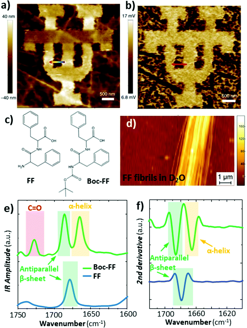 | ||
Fig. 10 (a) Topography of a 50 nm thick PMMA pattern on a germanium prism and (b) the corresponding RE-AFM-IR chemical map at 1730![[thin space (1/6-em)]](https://www.rsc.org/images/entities/char_2009.gif) cm−1 measured in D2O. Adapted with minor changes with permission from M. Jin et al., Light Sci. Appl., 2017, 6, e17096. © The Authors. Distributed under a CC BY-NC-SA 4.0 License (https://creativecommons.org/licenses/by-nc-sa/4.0/).28 (c) Chemical structure of diphenylalanine (FF) and tert-butoxycarbonyl diphenylalanine (Boc-FF). (d) Topography of a ≈ 160 nm thick FF fibril on a ZnSe prism measured in D2O. (e) Comparison of FF averaged (n = 10) fibril (blue) and Boc-FF fibril (green) RE-AFM-IR spectra obtained in D2O in the amide I (green and yellow) and C = O stretching vibration (red) spectral ranges. (f) Second derivative of the spectra in panel e, used for accurate peak position and conformation determination. Adapted with permission from G. Ramer et al., ACS Nano, 2018 12, 6612–6619, Copyright (2018) American Chemical Society.24 cm−1 measured in D2O. Adapted with minor changes with permission from M. Jin et al., Light Sci. Appl., 2017, 6, e17096. © The Authors. Distributed under a CC BY-NC-SA 4.0 License (https://creativecommons.org/licenses/by-nc-sa/4.0/).28 (c) Chemical structure of diphenylalanine (FF) and tert-butoxycarbonyl diphenylalanine (Boc-FF). (d) Topography of a ≈ 160 nm thick FF fibril on a ZnSe prism measured in D2O. (e) Comparison of FF averaged (n = 10) fibril (blue) and Boc-FF fibril (green) RE-AFM-IR spectra obtained in D2O in the amide I (green and yellow) and C = O stretching vibration (red) spectral ranges. (f) Second derivative of the spectra in panel e, used for accurate peak position and conformation determination. Adapted with permission from G. Ramer et al., ACS Nano, 2018 12, 6612–6619, Copyright (2018) American Chemical Society.24 | ||
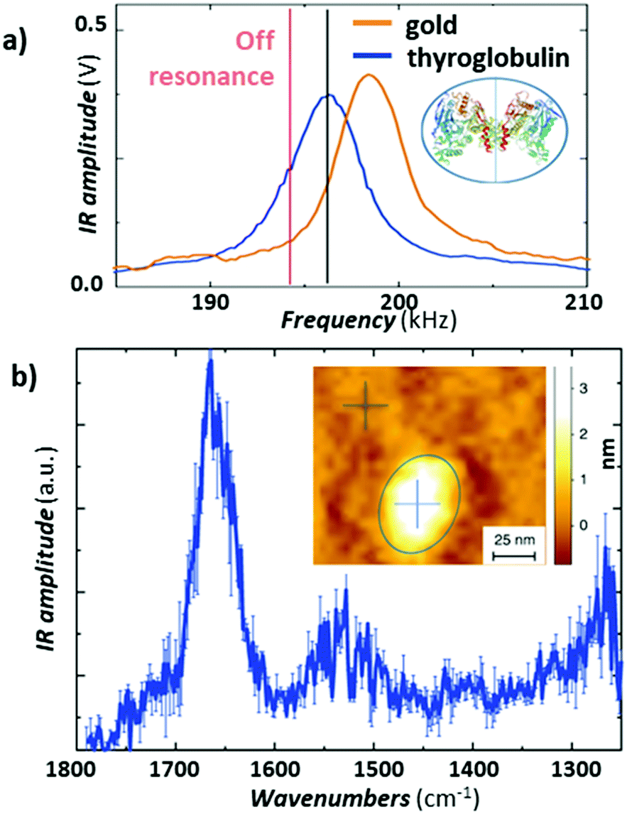
Recently, Ruggeri et al.57 expanded the limits of AFM-IR conformational characterization to the single protein level (Fig. 11). This feat was achieved by leveraging the plasmonic field enhancement in the gap between a gold-coated tip and gold-coated substrate. To limit the background absorption in the substrate and cantilever, the laser repetition rate was detuned by ≈ 1.5 kHz from the cantilever resonance (≈ 195 kHz) to maximize the signal-to-noise ratio (see Fig. 11a).57 Such detuning slightly decreases the signal from the protein sample but also strongly supresses the background absorption from the gold substrate, overall enhancing the signal-to-noise ratio. Given the strong plasmonic enhancement and the relatively soft proteins, a stable signal could be obtained only with low (< 0.35 mW) laser power. The result, obtained by subtracting the spectrum of the substrate from the spectrum of a single thyroglobulin protein and averaging 3 consecutively measured spectra, is presented in Fig. 11b, where the amide I and II bands are clearly visible at around 1650 cm−1 and 1550 cm−1. Deconvolution of the amide I band enabled secondary structure determination at the single-protein level, for thyroglobulin (665 kDa) and apoferritin (443 kDa), in good agreement with average macroscopic IR spectra.57
 | ||
| Fig. 11 (a) Comparison of the AFM-IR signal at 1655cm−1 measured as a function of the laser pulse frequency on the gold-coated substrate (orange) and on a thyroglobulin molecule (blue). Pulsing the laser (≈ 1.5 kHz) off resonance (red line) reduces the absorption background from the substrate and improves the signal-to-noise ratio for this sample. The thyroglobulin structure is displayed in the inset. (b) Average of three different substrate subtracted AFM-IR spectra on a single thyroglobulin protein with standard error. Inset: Topography of a single thyroglobulin protein (circled in blue). Figure contains material adapted with permission from F. S. Ruggeri et al., Nat. Commun., 2020, 11, 2945. © The Authors. Distributed under a CC-BY 4.0 License. (https://creativecommons.org/licenses/by/4.0/).57 | ||
An Interesting alternative and innovative approach to RE-AFM-IR measurements leverages a high-frequency off-resonance excitation and closed-loop (CL) piezo stage beneath the sample to maintain a null cantilever deflection (see Fig. 12a).44 In contrast to measuring the AFM-IR signal from the cantilever deflection, CL-AFM-IR uses a piezo actuator to maintain the cantilever deflection voltage at a specified frequency near zero-amplitude via real-time feedback controls. The piezo stage under the sample differs from the stage used to track the sample topography and provides an output voltage that is proportional to sample photothermal expansion. The main advantages of this closed-loop, null-deflection strategy are reduced influence of time varying changes in the cantilever resonance oscillation and reduced noise, particularly for cases where weak signals are recorded on top of a stronger background signal, which otherwise would amplify the noise in open-loop operation. The increased signal-to-noise ratios enabled by the CL approach can be seen in Fig. 12b–d, showing a side-by-side comparison to RE-AFM-IR measurements on a very thin (≈ 4 nm) PMMA sample.
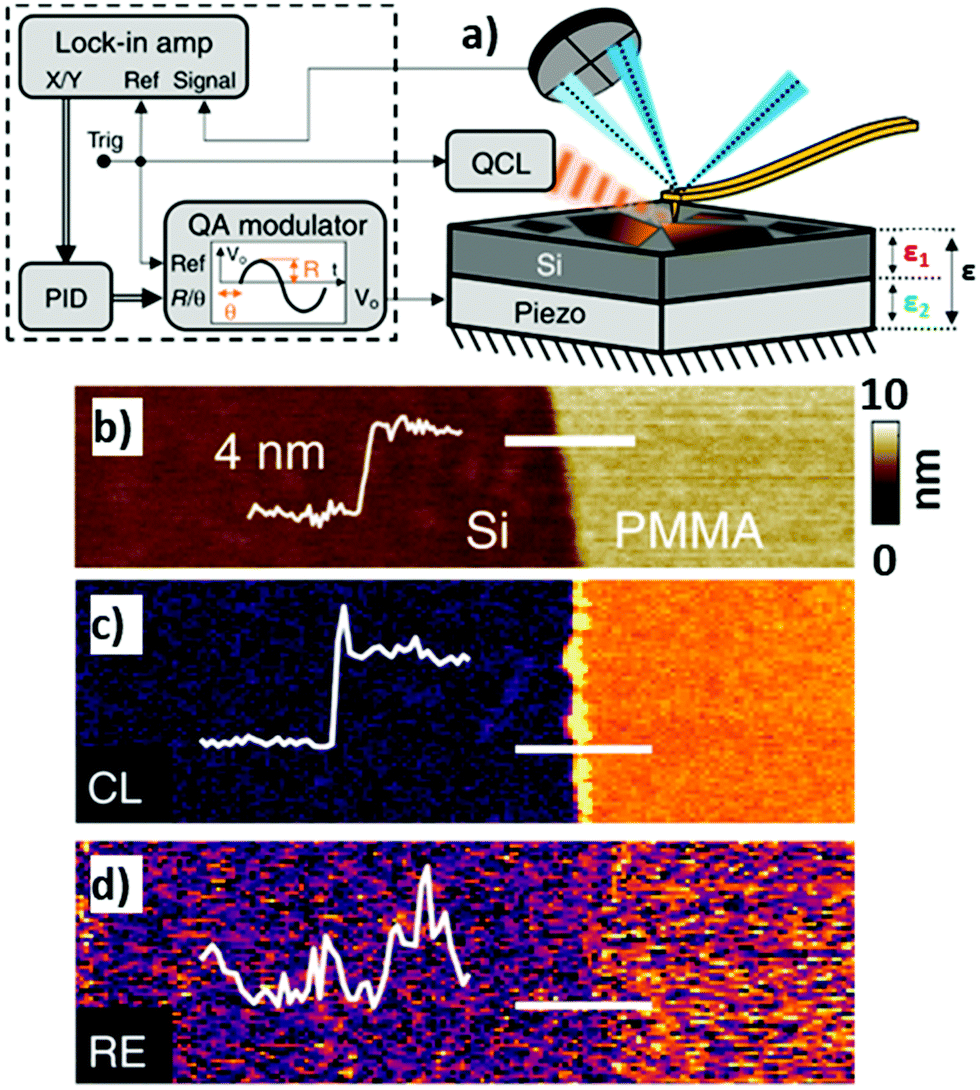 | ||
| Fig. 12 (a) Closed-loop (CL) AFM-IR schematic (right) with QCL and piezo induced harmonic expansion amplitudes ε1 and ε2 respectively. The total expansion amplitude ε is detected via the cantilever's deflection signal, which is demodulated using a dual lock-in amplifier (left). The x and y demodulated signals are processed via a discrete-time proportional, integral, derivative (PID) controller, the output of which is fed to a quadrature amplitude modulator (QAM). The QAM harmonic voltage output is used to drive the piezo expansion. (b) Topography of a 4 nm thick PMMA film on silicon with overlaid topographic profile (thin white line) measured across the film edge (indicated by thick white line). (c) Off-resonance (500 kHz) CL-AFM-IR and (d) RE-AFM-IR (460 kHz, on resonance with PLL) maps obtained at 1732 cm−1 (PMMA carboxylate absorption). The overlaid signal profiles highlight the respective signal-to-noise ratios of each modality, measured across the film edge. An edge artifact is evident along the film edge in (c). Figure contains material adapted with permission from S. Kenkel et al., Nat. Commun., 2020, 11, 3225. © The Authors. Distributed under a CC-BY 4.0 License (https://creativecommons.org/licenses/by/4.0/).44 | ||
Typically, AFM-IR spectra are obtained by sequentially measuring and stitching the signal intensity as a function of wavelength. Interestingly, broadband (4000 cm−1 to 900 cm−1) RE-AFM-IR spectra (16 cm−1 and 100 nm spectral and spatial resolution, respectively) were obtained at once using a synchrotron light source (< 1 mW) sinusoidally modulated by a chopper to match one of the cantilever resonant frequencies (≈ 70 kHz).50 Broadband detection was achieved by operating a Fourier transform IR (FTIR) interferometer at a 2.5 kHz scan rate with lock-in detection.50 However, the long signal integration times of this setup (8 min to 10 min for a spectral rage of ≈ 3000 cm−1) need to be greatly improved to outperform QCL based systems (1 s to 10 s for a spectral range of ≈ 1000 cm−1).
Proof-of-principle measurements that extend RE-AFM-IR to the visible spectrum were made on a chlorophyll-a monolayer and methylene-blue-stained amyloid fibrils using a laser with fixed wavelength (671 nm) and tunable repetition rate (1 kHz to 200 kHz).59 Although these experiments have achieved monolayer sensitivities the current lack of wavelength tunability limits their spectroscopic utility. By comparison, less sensitive measurements using the ringdown modality and OPOs with fixed (1 kHz) repetition rate enable experiments over a wide wavelength range (500 nm to 2300 nm)8,17 which is critical to determine the bandgap and optically active defects.
In addition to measuring vibrational (in the mid-IR) and electronic (in the visible) excitations, AFM-IR has been also employed to measure plasmonic23,30,34 and polaritonic38,39,43,54 modes. Some nano-optics applications, such as mapping surface-enhanced IR absorption intensity near plasmonic nanostructures23,30,34 and the characterization of dark plasmonic23,30 and polaritonic39,43 modes in metallic and 2D-material nanostructures, have been discussed in earlier reviews4,5 (and references therein). More recently, AFM-IR was used to characterize hyperbolic phonon polaritons (HPhPs), hybrid excitations of light and coherent lattice vibrations in polar crystals such as hBN38 and MoO3.54 These excitations can be generated within spectral bands delimited by pairs of longitudinal and transverse optical phonon modes and propagate through the material with large, quantized momenta and high optical compressions, λ0/λHPhP ≈ 100. In AFM-IR absorption images (e.g., Fig. 13b), HPhPs appear as fringes around sharp material discontinuities where HPhPs are generated or reflected strongly. Although HPhP characteristics are primarily determined by the host material, the polariton field also evanescently senses the surrounding media, which influences HPhP propagation lengths, lifetimes, and in-plane momentum. These effects are evident in the distribution and spatial frequencies of the polariton fringes seen in Fig. 13, which directly compares HPhPs in a single-crystal flake of α-MoO3 deposited on a SiO2 grating. Within regions of the MoO3 crystal suspended over air-filled trenches the polaritons propagate over longer distances and with lifetimes > 10 ps. By contrast, polaritons propagating in the same crystal within regions directly supported by the SiO2 substrate have shorter propagation lengths and lifetimes (≈ 5 ps), but a ≈ 1.5× higher optical confinement.
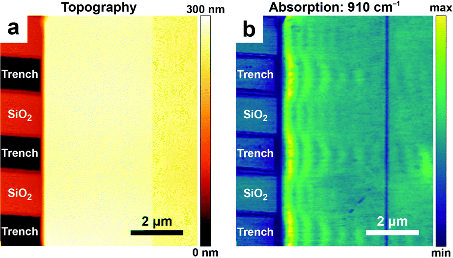 | ||
| Fig. 13 (a) Topography and (b) AFM-IR absorption map at 910 cm−1 of hyperbolic phonon polaritons (HPhPs) propagating within a ≈ 185 nm thick single-crystal of α-MoO3 deposited on a SiO2 grating substrate. Periodic variations (fringes) in the absorption signal evident in (b) are characteristic of the HPhP mode. Within suspended regions of MoO3 (over air-filled trenches in the substrate), HPhP propagate longer distances from the crystal edge and have longer lifetimes (τ > 10 ps), compared with HPhPs in regions directly contacted by the SiO2 substrate (τ ≈ 5 ps). Figure adapted with minor changes with permission from J. J. Schwartz et al., Nanophotonics, 2021, 10, 1517–1527. (C) The Authors. Distributed under a CC-BY 4.0 License. (https://creativecommons.org/licenses/by/4.0/).54 | ||
5. Tapping mode AFM-IR
5.1 Tapping mode AFM-IR tutorial
In contrast to contact mode, AFM measurements in tapping mode utilize an oscillating probe that only intermittently contacts (“taps”) the surface, thereby minimizing the lateral forces exerted by the probe that could damage very soft or delicate samples.Tapping mode measurements begin by identifying the free cantilever resonance frequencies when the probe is not interacting with the sample, as shown in Fig. 2c. Next, the driving (tapping) frequency is selected, typically at or near the first or second resonance modes (i.e., f1 or f2) since these modes have the greatest sensitivities. After engaging the tip near the surface, the amplitude and phase of these oscillations change due to the tip–sample interactions. A feedback loop adjusts the tip position above the surface to maintain a constant oscillation amplitude for conventional tapping mode AFM imaging (e.g., topography and phase maps). The tapping mode AFM-IR signal, however, is based on a heterodyne detection scheme that exploits the highly non-linear interaction potential between the tip and the sample surface. In this scheme, while the cantilever is driven near one resonance mode (e.g., f2), a wavelength-tunable laser is pulsed at the sum or difference frequency of two neighboring mode (e.g., fpulse = f2 − f1). During each tapping cycle, frequency mixing between the photothermal excitation of the sample (at fpulse) and the driven cantilever oscillations (e.g., at f2) induce excitations in the cantilever at the neighboring resonance mode (e.g., f1). Dazzi and coworkers derived an expression19 for the demodulated (heterodyned) cantilever oscillation amplitude (Z) in AFM-IR experiments, which is simplified here as:
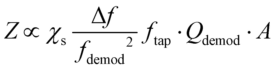 | (4) |
After tuning the instrument to produce reliable topography maps when tapping at f2, the laser pulse repetition rate is swept over a frequency range around f2 − f1 to maximize the demodulated AFM-IR signal.9 This optimal pulse rate should be maintained with a PLL, if available, for improved reproducibility.11 Detection of the AFM-IR signal at a different frequency from the laser pulse rate suppresses sensitivity to non-specific, background absorption by the cantilever and more distant regions of the sample, thereby increasing signal-to-noise ratios and the spatial resolution of the measurement.
5.2 Tapping mode AFM-IR application examples
The first tapping mode AFM-IR publications were reported by Tuteja et al.18 and, shortly after, by Mathurin et al.19 in 2018. Since then, tapping mode AFM-IR studies have been used to study drug delivery,9,18,19,60 geology,61 art conservation,3,12 and nanophotonics38,39 applications, mainly characterizing samples too soft,9 too sticky,18 or too rough3,12 for contact mode measurements, or samples that are easily damaged9 or displaced19,60 by contact mode tips. For example, Tuteja et al. used tapping mode AFM-IR to characterize the distribution of paclitaxel, an effective but difficult-to-deliver chemotherapeutic drug, in lipid, polymer, and hybrid lipid–polymer membranes that are too sticky to the tip for contact mode measurements.18 The authors found that that paclitaxel phase separates as nano-crystals from lipid films, thus reducing the drug bioavailability, but it is well-dispersed in polymer-only films. Furthermore, it was found that the distribution of paclitaxel in lipid–polymer hybrid films is enhanced at the lipid–polymer phase boundaries, which synergistically stifle crystallization and boost the released drug payload.18 Mathurin et al.19 visualized the composition of small (< 200 nm) core–shell polymeric nanoparticles loaded with pipemidic acid (an antibacterial agent) that were too loosely adhered to the substrate for contact mode measurements. In a related application, Wieland et al. used RE-AFM-IR and tapping mode AFM-IR to characterize the distribution of the anticancer drug cytarabine inside small (< 80 nm diameter) single liposomes, detecting just ≈ 103 cytarabine molecules (≈ 1.7 zmol) with ≈ 10 nm spatial resolution.9 Although those liposomes could be measured (through great effort) using contact mode, their very low mechanical stiffness made the signal transduction inefficient52 and increased the likelihood of tip-induced sample damage in those conditions. Since tapping AFM is commonly used to measure soft biological samples, tapping mode AFM-IR did not damage the mechanically compliant (soft) liposomes even when increasing the scan rate ≈ 2- to ≈ 5-fold.9 Pierges et al. used tapping mode AFM-IR to deduce the orientation of erlotinib molecules absorbed on monolayers made by silver or gold nanoparticles (≈ 15 nm diameter).60 The authors determined that the drug interacts with the Au and Ag nanoparticles mainly through phenyl rings and methoxy moieties because their characteristic vibrational peaks selectively increase in intensity and broaden, as expected for dipoles aligned perpendicular to metal surfaces via the surface-enhanced IR absorption effect.Asphalt is composed of mineral aggregate and a small faction (≈ 5% by weight) of bitumen as a binder. Bitumen is a very heterogeneous mixture of molecules, typically grouped in four main hydrocarbon fractions (saturates, aromatics, resins, and asphaltenes) that form distinct surface domains named catana, para, and peri domains.61 Using tapping mode AFM-IR together with a thermoelectric sample stage inside an environmental chamber, Baheri et al.61 were able to determine the relative chemical abundance of bitumen surface domains over a range of temperatures (243 K to 298 K) and compared it to the average bulk composition determined by FTIR. The authors discovered that, at low temperatures, an additional type of (transition) domain forms between the para and peri domains, and new subdomains forms within the para domains (see Fig. 14), which may be important for the binding performance in sub-freezing temperatures.61 We believe that this is the first report using AFM-IR at non-ambient temperatures.
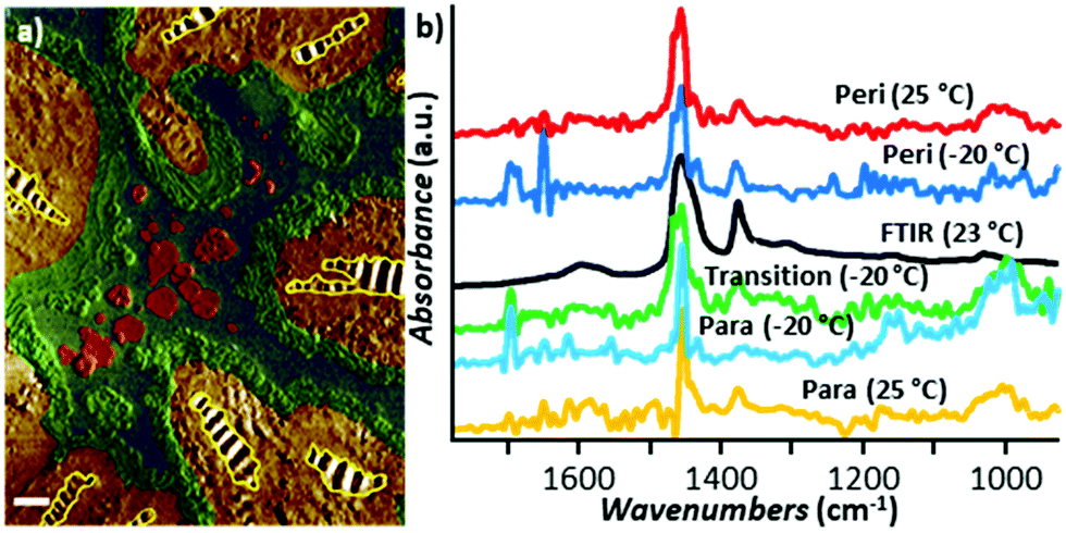 | ||
| Fig. 14 (a) False-color tapping phase image of bitumen obtained at −20 °C with chemical domains identified based on AFM-IR analysis. The catana domains (yellow stripes) are surrounded by the peri domains (yellow). The transition domains (green) are located between the peri and para (blue domains), which contain sal subdomains (red). Scale bar: 1 μm. (b) Smoothed tapping mode AFM-IR spectra of para (yellow) and peri (red) domains at 25 °C and of para (cyan), peri (blue), and transition (green) domains at −20 °C compared to the bulk FTIR spectra (black) obtained at 23 °C. Adapted from F. Tarpoudi Baheri et al., J. Microsc., 2020, 279, 3–15. DOI: https://doi.org/10.1111/jmi.12890. © Royal Microscopical Society. Reproduced with permission. All rights reserved.61 | ||
Early tapping mode AFM-IR experiments used moderately stiff cantilevers (≈ 4 N m−1)18 tapping at f1 ≈ 50 kHz, demodulating the signal at f2 ≈ 350 kHz, and pulsing the laser at fpulse = f2 − f1 ≈ 300 kHz. As mentioned previously, signal-to-noise considerations19,39 favor the use of stiffer cantilevers that are characterized by a larger gap between the resonant frequencies of the first two modes.19 Ma et al.12 first used stiffer cantilevers (≈ 40 N m−1) for AFM-IR by tapping at f2 ≈ 1550 kHz, demodulating the signal at f2 ≈ 250 kHz, and pulsing the laser at fpulse = f2 − f1 ≈ 1300 kHz to measure rough oil paint samples that were too very difficult to measure with the softer tapping mode probes. Slow chemical reactions between the constituents of the paint (e.g., pigments, oils, and additives) can lead to paint degradation and impair the conservation of works of art. A common, but not well understood, damaging reaction between the paint constituents leads to the formation of metal carboxylates (soaps), which can be identified by characteristic IR absorption peaks. However, the extreme heterogeneity of oil paints and the spatial resolution limits of conventional IR microscopy hindered efforts to understand the root cause of metal soap formation and evolution to damaging aggregates. Tapping mode AFM-IR images and spectra reveal that the types of intertwined carboxylate species is greater and their distribution more complex than previously thought, first in a 23-year-old naturally aged commercial paint12 of known average composition and later on a 19th-century French painting3 of unknown composition (see Fig. 15). The latter sample was found to be a mixture of cobalt green and lead white pigments, cured oil, and at least three distinct zinc soaps that form intermixed domains often much smaller than ≈ 0.1 μm3.
 | ||
| Fig. 15 (a) AFM-IR spectra from a ≈ 400 nm thick cross section sample of Jean–Baptiste–Camille Corot, Gypsy Woman with Mandolin, c. 1870. The spectra were obtained at the indicated locations in panels b. (b) Reconstructed false-color map of PTIR absorption displaying overlaid absorption intensities of Zn stearate (1540 cm−1, red), disordered tetrahedral Zn-soap (1591 cm−1, green), and Zn oleate (1552 cm−1, blue). Inset: magnified view of the area delimited by the rectangle in b. Figure adapted with permission from X. Ma, et al. Anal. Chem., 2022, Copyright (2022) American Chemical Society.3 | ||
Another application that has benefitted from tapping mode is the AFM-IR characterization of hyperbolic phonon polariton excitation in hexagonal boron nitride (hBN) nanostructures39 and flakes.38 Ramer et al. measured hBN frusta nanostructures with steep edges using RE-AFM-IR with moderate (≈ 4 N m−1) stiffness cantilevers and tapping mode AFM-IR with both moderate (≈ 4 N m−1) and high (≈ 40 N m−1) stiffness cantilevers. All three type of measurements provided qualitatively similar results, however, the signal-to-noise ratios on these samples was lowest using tapping mode AFM-IR measurements with moderate stiffness cantilevers, while contact mode (RE-AFM-IR) measurements resulted in tip-induced damage to the smallest structures.39 Additional discussion on the characterization of HPhPs has been discussed in Section 4 (Fig. 13) and in an earlier review.5 With the introduction of the stiffer cantilevers, tapping mode AFM-IR is very similar to photo-induced force microscopy (PiFM),62 with the main difference appearing to be the tip–sample force, which is attractive in PiFM (referred as non-contact mode) but repulsive in tapping mode AFM-IR measurements.
6. Novel AFM-IR measurement paradigms
6.1 Peak force tapping IR (PFIR) tutorial
Recently, PFIR was introduced as a new AFM-IR variant, leveraging the peak force tapping mode of AFM,20 in which the separation between sample stage and the probe is modulated sinusoidally at a fixed frequency (e.g., 2 kHz to 4 kHz), far below the AFM cantilever mechanical resonances (Fig. 16a). During each modulation cycle, the AFM probe makes intermittent contact with the sample, resulting in a vertical probe deflection signal at the detector (Fig. 16a, blue trace). The maximum deflection is used as the setpoint for the peak force tapping feedback. Chemical imaging is achieved by focusing a tunable IR laser at the tip–sample interface and synchronizing the laser pulse with the maximum probe deflection. The photothermal expansion of the sample induces cantilever oscillations with an amplitude proportional to the absorbed energy by the sample. (Fig. 16a, red trace). The PFIR trace (Fig. 16a, inset) is extracted by subtracting the (blue) background deflection trace (obtained without illumination) from the (red) deflection curve with the IR-induced cantilever oscillations. In this scheme, the repetition rate of the IR laser is half of the tapping frequency and the PFIR trace is obtained over two successive tapping cycles. Alternatively, the PFIR trace can be obtained from every cycle by setting the laser repetition rate of the IR laser equal to the peak force tapping frequency and subtracting a 4th-order polynomial fit from each deflection curve to remove the background deflection.63 In either case, the PFIR signal intensity is obtained through a Fourier transform and subsequent integration of cantilever resonance peaks in frequency space. | ||
| Fig. 16 (a) Cantilever deflection traces measuring intermittent contact with the sample during peak force tapping with laser pulses (red trace) and without laser pulses (blue trace). For reference, the IR-laser pulse is indicated in black. The inset shows the extracted PFIR trace. Adapted with minor changes with permission from L. Wang et al., Sci. Adv., 2017, 3, e1700255. © The Authors, some rights reserved; exclusive licensee AAAS. Distributed under a CC-BY 4.0 License. (https://creativecommons.org/licenses/by/4.0/)17 (b) Topography map of a single-crystal MAPbBr3 sample that was purposely degraded on the right half of the imaged area. (c) PFIR chemical map of methyl ammonium ion absorption (1480 cm−1). (d) Elastic modulus map. (e) Surface potential map. All channels are acquired simultaneously. Adapted with permission from D. S. Jakob et al., Angew. Chem., Int. Ed., 2020, 59, 16083–16090. © 2020 Wiley-VCH Verlag GmbH & Co. KGaA, Weinheim.18 | ||
Peak force tapping operation, and by extension PFIR, is compatible with many AFM probe types and is particularly useful on rough and sticky samples that are not suitable for contact mode AFM-IR. The primary benefit of PFIR is the ability to simultaneously map chemical, topographic, mechanical (e.g., adhesion, modulus) and, more recently, surface potential properties at comparable and high spatial resolution (< 10 nm), thereby enabling detailed correlations between several important material properties.21
6.2 AFM-IR surface sensitivity mode
A new AFM-IR mode based on a heterodyne detection scheme, named surface sensitivity mode, was recently introduced by Dazzi and co-workers. This mode is based on force modulation microscopy (FMM), a contact mode AFM technique that, in addition to the sample topography, also provides qualitative nanomechanical properties (stiffness, adhesion) of the top 10 nm to 30 nm of the sample. The technique's surface sensitivity stems from a piezo-driven high-frequency modulation applied to the cantilever that periodically modulates the tip–sample contact force (and the tip indentation in the sample). In the surface sensitivity AFM-IR mode the laser repetition rate (fpulse) and the force modulation frequency (fmod) are chosen so that their difference (or sum) matches one of the high-Q AFM contact resonance frequencies (fdem = fmod ± fpulse), which is used for signal demodulation (see Fig. 17). The modulation frequency (fmod) can be chosen to match one of the several contact resonance frequencies but the detection scheme, in principle, should also work using off-resonance modulation. Although this novel AFM-IR mode is barely beyond proof-of-principle demonstrations, we believe that it has the potential for widespread adoption due to its near-surface probed depth (≈ 25 nm),11 which should enable high spatial resolution chemical imaging on heterogeneous samples with very small domains and to investigate sample stratification in combination with RE-AFM-IR (> 500 nm probed depths)22 and tapping mode AFM-IR (≈ 50 nm probed depths).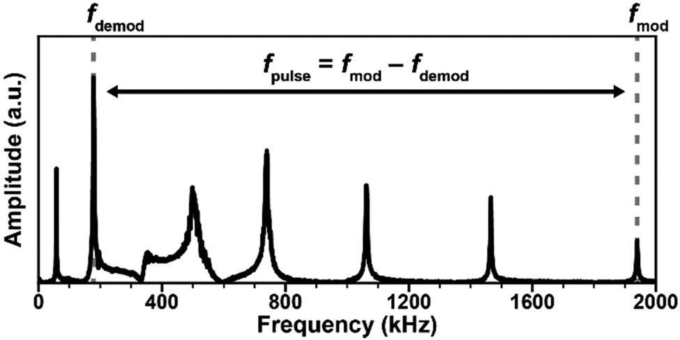 | ||
| Fig. 17 Representative resonant frequencies of a soft contact mode AFM cantilever. In surface-sensitivity AFM-IR the tip–sample force and indentation is modulated at high frequency (in the example above, fmod ≈ 1940 kHz, was chosen to coincide with one of the contact mechanical resonances). The AFM-IR signal is demodulated in correspondence of a high-Q cantilever mode (fdemod ≈ 178 kHz, above) while the IR laser illuminating the sample is pulsed fpulse = fmod − fdem ≈ 1762 kHz, above. | ||
7. Conclusions and prospects
Since its inception27 and commercialization, AFM-IR has greatly exceeded initial expectations of spatial resolution, sensitivity, probed depth, measurement throughput. For example, since initial assessments,14 the typical AFM-IR spatial resolution (≈ 100 nm) and acquisition time for a 1000 cm−1 wide spectrum (≈ 240 s) has been reduced to ≈ 4 nm and ≈ 10 s, respectively.3 This was possible thanks to the rapid technical innovation of AFM-IR detection schemes,7,12,18,20,27 nanofabricated probes,25,64 and to the adoption of new wavelength-tunable laser sources.7,8,26 The AFM-IR signal proportionality to the (local) sample absorption coefficient is the core notion that enables well-established IR spectroscopic correlations at the nanoscale such as: identification of functional groups, materials, molecular conformations, polymorphic forms, and isotopes. Besides these classic IR applications, AFM-IR (PTIR) has enabled nanoscale studies of optical modes in the mid-IR (plasmons and polaritons) and measurements of optical properties such as bandgap and defects in the visible and near-IR. Additionally, AFM-IR measurements using optomechanical probes that measure the full time-domain sample thermalization can also determine the sample thermal conductivity and its interfacial thermal conductance with the substrate with nanoscale resolution.64 Thanks to the increased availability of AFM-IR instrumentation together with its broad applicability and utility, the number of publications have grown steadily, impacting an ever-expanding list of disciplines such as biology, material science, photonics, optoelectronics, drug delivery, medicine, geology, art conservation, etc., as detailed in earlier reviews.4–6,10,11The recent availability of different AFM-IR modalities offering a range of sensitivities, spatial resolutions, probed depths, and interactions with the sample, provide users with options for achieving best results as function of the sample characteristics. In this review, we provide general guidance on choosing the AFM-IR measurement modalities based on our hands-on experience. Since ringdown measurements typically have lower sensitivities, they are not used often in the mid-IR but are still the method of choice in the visible and near-IR due to its compatibility with suitable tunable laser in these ranges. Resonance-enhanced measurements provide much higher sensitivities and throughputs in the mid-IR and are typically the preferred choice for samples with composition boundaries that are perpendicular to the substrate and for measuring the composition of sample throughout its thickness, such as thin films. Tapping mode AFM-IR is typically advantageous for samples that are too soft, too, sticky, too rough, easily displaced or damaged by the AFM tip when operating in contact mode. Additionally, since the depths probed by tapping mode AFM-IR (≈ 50 nm) are significantly shallower than for RE-AFM-IR (> 500 nm), it also typically provides higher spatial resolutions. However, for samples thicker than the tapping mode AFM-IR probed depths (≈ 50 nm), RE-AFM-IR often provide higher signal-to-noise ratios. The strong suites of PIFR are similar to tapping mode AFM-IR with the added benefits of measurements correlation across several properties of the sample. We believe that, the even shallower probed depths (≈ 25 nm) of the surface sensitivity mode will be advantageous to measure the composition of samples with very small chemical domains (whose details would be smeared out in measurements probing deeper into the sample) and will offer a way to study the sample stratigraphy in combination with other AFM-IR modalities. The dependence of AFM-IR signal intensities on the tip–sample contact dynamics via the scaling factor, however, poses challenges to measurements quantification and may introduce artefacts, particularly for resonant AFM-IR detection schemes. These effects can be minimized with off-resonant excitations (ringdown), with close loop operation,44 and (to a degree) with spectral ratios.52 Alternatively, inversion of the AFM-IR signal is a general approach that enables quantitative analysis but requires measurements of two spectra with different polarizations (s and p) at each location, which has so far limited its application.15
Going forward, we expect that novel AFM-IR variants with improved measurement sensitivities and throughputs will be developed alongside methods that minimize the influence of the scaling factors, enabling quantitative applications. In general, current and future AFM-IR variants will benefit from the fast-paced development of laser sources with broader spectral ranges and higher repetition rates. Given the rapid progress in laser research, an enticing possibility that may soon be within reach is the extension of AFM-IR (PTIR) to the THz spectral range.
Another area primed for growth is the extension of AFM-IR to different environments: in liquids, in vacuum, and at cryogenic temperatures. Given the importance of measurements in water-based media for biological applications and the availability of different water compatible AFM-IR modalities, we expect growth beyond proof-of-principle demonstrations.24,28 We believe that the need for even higher spatial resolutions (< 1 nm), sensitivities (e.g., to measure small single-molecules) and to characterize quantum effects will spur efforts develop new ultrahigh vacuum, cryogenic AFM-IR instrumentation. Taking advantage of the atomistic near-field such measurement could in principle aim to achieve the dream of atomic resolution IR spectroscopy.
Given the increasing number of AFM-IR practitioners and instrument deployed worldwide, and the synergistic innovations, in lasers, AFM-IR technology, and theory we think that AFM-IR will foster a steadily increasing number of applications and impact an ever-greater number of fields.
Author contributions
J. J. S: visualization, writing – original draft, D. S. J.: visualization, writing – review & editing, A. C.: conceptualization, supervision, visualization, writing – original draft.Conflicts of interest
There are no conflicts to declare.Acknowledgements
This research was performed while Jeffrey Schwartz held an NRC Research Associateship award at the Laboratory for Physical Sciences. D. S. Jakob acknowledges financial support from the NIST-Georgetown University Professional Research Experience Program.References
- T. P. Wrobel and R. Bhargava, Anal. Chem., 2018, 90, 1444–1463 CrossRef CAS PubMed.
- B. J. Davis, P. S. Carney and R. Bhargava, Anal. Chem., 2010, 82, 3487–3499 CrossRef CAS PubMed.
- X. Ma, G. Pavlidis, E. Dillon, V. Beltran, J. J. Schwartz, M. Thoury, F. Borondics, C. Sandt, K. Kjoller, B. H. Berrie and A. Centrone, Anal. Chem., 2022, 94, 3103–3110 CrossRef CAS PubMed.
- A. Centrone, Annu. Rev. Phys. Chem., 2015, 8, 101–126 CrossRef CAS PubMed.
- D. Kurouski, A. Dazzi, R. Zenobi and A. Centrone, Chem. Soc. Rev., 2020, 49, 3315–3347 RSC.
- A. Dazzi and C. B. Prater, Chem. Rev., 2017, 117, 5146–5173 CrossRef CAS PubMed.
- F. Lu, M. Jin and M. A. Belkin, Nat. Photonics, 2014, 8, 307–312 CrossRef CAS.
- A. M. Katzenmeyer, G. Holland, K. Kjoller and A. Centrone, Anal. Chem., 2015, 87, 3154–3159 CrossRef CAS PubMed.
- K. Wieland, G. Ramer, V. U. Weiss, G. Allmaier, B. Lendl and A. Centrone, Nano Res., 2019, 12, 197–203 CrossRef CAS PubMed.
- K. Hinrichs and T. Shaykhutdinov, Appl. Spectrosc., 2018, 72, 817–832 CrossRef CAS PubMed.
- J. Mathurin, A. Deniset-Besseau, D. Bazin, E. Dartois, M. Wagner and A. Dazzi, J. Appl. Phys., 2022, 131, 010901 CrossRef CAS.
- X. Ma, V. Beltran, G. Ramer, G. Pavlidis, D. Y. Parkinson, M. Thoury, T. Meldrum, A. Centrone and B. H. Berrie, Angew. Chem., Int. Ed., 2019, 58, 11652–11656 CrossRef CAS PubMed.
- A. Dazzi, F. Glotin and R. Carminati, J. Appl. Phys., 2010, 107, 124519 CrossRef.
- B. Lahiri, G. Holland and A. Centrone, Small, 2013, 9, 439–445 CrossRef CAS PubMed.
- G. Ramer, V. A. Aksyuk and A. Centrone, Anal. Chem., 2017, 89, 13524–13531 CrossRef CAS PubMed.
- J. Chae, Q. Dong, J. Huang and A. Centrone, Nano Lett., 2015, 15, 8114–8121 CrossRef CAS PubMed.
- Y. Yoon, J. Chae, A. M. Katzenmeyer, H. P. Yoon, J. Schumacher, S. An, A. Centrone and N. Zhitenev, Nanoscale, 2017, 9, 7771–7780 RSC.
- M. Tuteja, M. Kang, C. Leal and A. Centrone, Analyst, 2018, 143, 3808–3813 RSC.
- J. Mathurin, E. Pancani, A. Deniset-Besseau, K. Kjoller, C. B. Prater, R. Gref and A. Dazzi, Analyst, 2018, 143, 5940–5949 RSC.
- L. Wang, H. Wang, M. Wagner, Y. Yan, D. S. Jakob and X. G. Xu, Sci. Adv., 2017, 3, e1700255 CrossRef PubMed.
- D. S. Jakob, H. Wang, G. Zeng, D. E. Otzen, Y. Yan and X. G. Xu, Angew. Chem., Int. Ed., 2020, 59, 16083–16090 CrossRef CAS PubMed.
- L. Baldassarre, V. Giliberti, A. Rosa, M. Ortolani, A. Bonamore, P. Baiocco, K. Kjoller, P. Calvani and A. Nucara, Nanotechnology, 2016, 27, 075101 CrossRef CAS PubMed.
- B. Lahiri, G. Holland, V. Aksyuk and A. Centrone, Nano Lett., 2013, 13, 3218–3224 CrossRef CAS PubMed.
- G. Ramer, F. S. Ruggeri, A. Levin, T. P.-J. Knowles and A. Centrone, ACS Nano, 2018, 12, 6612–6619 CrossRef CAS PubMed.
- J. Chae, S. An, G. Ramer, V. Stavila, G. Holland, Y. Yoon, A. A. Talin, M. Allendorf, V. A. Aksyuk and A. Centrone, Nano Lett., 2017, 17, 5587–5594 CrossRef CAS PubMed.
- A. M. Katzenmeyer, V. Aksyuk and A. Centrone, Anal. Chem., 2013, 85, 1972–1979 CrossRef CAS PubMed.
- A. Dazzi, R. Prazeres, F. Glotin and J. M. Ortega, Opt. Lett., 2005, 30, 2388–2390 CrossRef CAS PubMed.
- M. Jin, F. Lu and M. A. Belkin, Light: Sci. Appl., 2017, 6, e17096 CrossRef CAS PubMed.
- A. M. Katzenmeyer, G. Holland, J. Chae, A. Band, K. Kjoller and A. Centrone, Nanoscale, 2015, 7, 17637–17641 RSC.
- A. M. Katzenmeyer, J. Chae, R. Kasica, G. Holland, B. Lahiri and A. Centrone, Adv. Opt. Mater., 2014, 2, 718–722 CrossRef CAS.
- J. J. Schwartz, H.-J. Chuang, M. R. Rosenberger, S. V. Sivaram, K. M. McCreary, B. T. Jonker and A. Centrone, ACS Appl. Mater. Interfaces, 2019, 11, 25578–25585 CrossRef CAS PubMed.
- V. Giliberti, R. Polito, E. Ritter, M. Broser, P. Hegemann, L. Puskar, U. Schade, L. Zanetti-Polzi, I. Daidone, S. Corni, F. Rusconi, P. Biagioni, L. Baldassarre and M. Ortolani, Nano Lett., 2019, 19, 3104–3114 CrossRef CAS PubMed.
- C.-T. Wang, B. Jiang, Y.-W. Zhou, T.-W. Jiang, J.-H. Liu, G.-D. Zhu and W.-B. Cai, Anal. Chem., 2019, 91, 10541–10548 CrossRef CAS PubMed.
- A. B. Khanikaev, N. Arju, Z. Fan, D. Purtseladze, F. Lu, J. Lee, P. Sarriugarte, M. Schnell, R. Hillenbrand, M. A. Belkin and G. Shvets, Nat. Commun., 2016, 7, 1–8 Search PubMed.
- J. Waeytens, J. Mathurin, A. Deniset-Besseau, V. Arluison, L. Bousset, H. Rezaei, V. Raussens and A. Dazzi, Analyst, 2021, 146, 132–145 RSC.
- L. Gong, D. B. Chase, I. Noda, C. A. Marcott, J. Liu, D. C. Martin, C. Ni and J. F. Rabolt, Macromolecules, 2017, 50, 5510–5517 CrossRef CAS.
- Z. Wang, B. Sun, X. Lu, C. Wang and Z. Su, Macromolecules, 2019, 52, 9639–9645 CrossRef CAS.
- G. Pavlidis, J. J. Schwartz, J. Matson, T. Folland, S. Liu, J. H. Edgar, J. D. Caldwell and A. Centrone, APL Mater., 2021, 9, 091109 CrossRef CAS.
- G. Ramer, M. Tuteja, J. R. Matson, M. Davanco, T. G. Folland, A. Kretinin, T. Taniguchi, K. Watanabe, K. S. Novoselov, J. D. Caldwell and A. Centrone, Nanophotonics, 2020, 9, 1457–1467 CAS.
- L. Xiong, Y. Chen, J. Yu, W. Xiong, X. Zhang and Y. Zheng, Appl. Phys. Lett., 2019, 115, 153107 CrossRef.
- F. Tang, P. Bao and Z. Su, Anal. Chem., 2016, 88, 4926–4930 CrossRef CAS PubMed.
- D. Perez-Guaita, K. Kochan, M. Batty, C. Doerig, J. Garcia-Bustos, S. Espinoza, D. McNaughton, P. Heraud and B. R. Wood, Anal. Chem., 2018, 90, 3140–3148 CrossRef CAS PubMed.
- L. V. Brown, M. Davanco, Z. Sun, A. Kretinin, Y. Chen, J. R. Matson, I. Vurgaftman, N. Sharac, A. J. Giles, M. M. Fogler, T. Taniguchi, K. Watanabe, K. S. Novoselov, S. A. Maier, A. Centrone and J. D. Caldwell, Nano Lett., 2018, 18, 1628–1636 CrossRef CAS PubMed.
- S. Kenkel, S. Mittal and R. Bhargava, Nat. Commun., 2020, 11, 3225 CrossRef CAS PubMed.
- A. Hammiche, H. M. Pollock, M. Reading, M. Claybourn, P. H. Turner and K. Jewkes, Appl. Spectrosc., 1999, 53, 810–815 CrossRef CAS.
- L. Bozec, A. Hammiche, H. M. Pollock, M. Conroy, J. M. Chalmers, N. J. Everall and L. Turin, J. Appl. Phys., 2001, 90, 5159–5165 CrossRef CAS.
- L. Bozec, A. Hammiche, M. J. Tobin, J. M. Chalmers, N. J. Everall and H. M. Pollock, Meas. Sci. Technol., 2002, 13, 1217–1222 CrossRef CAS.
- S. Kenkel, A. Mittal, S. Mittal and R. Bhargava, Anal. Chem., 2018, 90, 8845–8855 CrossRef CAS PubMed.
- A. N. Morozovska, E. A. Eliseev, N. Borodinov, O. S. Ovchinnikova, N. V. Morozovsky and S. V. Kalinin, Appl. Phys. Lett., 2018, 112, 033105 CrossRef.
- K. L.-A. Chan, I. Lekkas, M. D. Frogley, G. Cinque, A. Altharawi, G. Bello and L. A. Dailey, Anal. Chem., 2020, 92, 8097–8107 CrossRef CAS PubMed.
- L. Quaroni, Anal. Chem., 2020, 92, 3544–3554 CrossRef CAS PubMed.
- D. E. Barlow, J. C. Biffinger, A. L. Cockrell-Zugell, M. Lo, K. Kjoller, D. Cook, W. K. Lee, P. E. Pehrsson, W. J. Crookes-Goodson, C.-S. Hung, L. J. Nadeau and J. N. Russell, Analyst, 2016, 141, 4848–4854 RSC.
- E. Strelcov, Q. Dong, T. Li, J. Chae, Y. Shao, Y. Deng, A. Gruverman, J. Huang and A. Centrone, Sci. Adv., 2017, 3, e1602165 CrossRef PubMed.
- J. J. Schwartz, S. T. Le, S. Krylyuk, C. A. Richter, A. V. Davydov and A. Centrone, Nanophotonics, 2021, 10, 1517–1527 CrossRef CAS.
- F. Chiti and C. M. Dobson, Annu. Rev. Biochem., 2017, 86, 27–68 CrossRef CAS PubMed.
- F. S. Ruggeri, G. Longo, S. Faggiano, E. Lipiec, A. Pastore and G. Dietler, Nat. Commun., 2015, 6, 7831 CrossRef CAS PubMed.
- F. S. Ruggeri, B. Mannini, R. Schmid, M. Vendruscolo and T. P.-J. Knowles, Nat. Commun., 2020, 11, 2945 CrossRef CAS PubMed.
- T. Dou, L. Zhou and D. Kurouski, J. Phys. Chem. Lett., 2021, 12, 4407–4414 CrossRef CAS PubMed.
- J. Zhou, A. Smirnov, G. Dietler and S. K. Sekatskii, Nano Lett., 2019, 19, 8278–8286 CrossRef CAS PubMed.
- N. Piergies, A. Dazzi, A. Deniset-Besseau, J. Mathurin, M. Oćwieja, C. Paluszkiewicz and W. M. Kwiatek, Nano Res., 2020, 13, 1020–1028 CrossRef CAS.
- F. Tarpoudi Baheri, T.-m Schutzius, D. Poulikakos and L.-d Poulikakos, J. Microsc., 2020, 279, 3–15 CrossRef CAS PubMed.
- D. Nowak, W. Morrison, H. K. Wickramasinghe, J. Jahng, E. Potma, L. Wan, R. Ruiz, T. R. Albrecht, K. Schmidt, J. Frommer, D. P. Sanders and S. Park, Sci. Adv., 2016, 2(3) DOI:10.1126/sciadv.1501571.
- H. Wang, L. Wang, E. Janzen, J. H. Edgar and X. G. Xu, Anal. Chem., 2021, 93, 731–736 CrossRef CAS PubMed.
- M. Wang, G. Ramer, D. J. Perez-Morelo, G. Pavlidis, J. J. Schwartz, L. Yu, R. Ilic, V. A. Aksyuk and A. Centrone, Nano Lett., 2022 DOI:10.1021/acs.nanolett.2c00337.
| This journal is © The Royal Society of Chemistry 2022 |