
 Open Access Article
 This Open Access Article is licensed under a
 Creative Commons Attribution 3.0 Unported Licence
Atomistic simulation of helium diffusion and clustering in plutonium dioxide†
Elanor
Murray
 *a,
Ying
Zhou
b,
Peter
Slater
a,
Roger
Smith
b,
Pooja
Goddard
b and
Helen
Steele
c
*a,
Ying
Zhou
b,
Peter
Slater
a,
Roger
Smith
b,
Pooja
Goddard
b and
Helen
Steele
c
aSchool of Chemistry, University of Birmingham, Birmingham, UK. E-mail: elanormurray@gmail.com
bSchool of Science, Loughborough University, Loughborough, UK
cSellafield Ltd, Sellafield, Cumbria, UK
First published on 25th July 2022
Abstract
This study uses molecular dynamics and barrier searching methods to investigate the diffusion and clustering of helium in plutonium dioxide. Such fundamental understanding of helium behaviour is required because radiogenic helium generated from the alpha decay of Pu nuclei can accumulate over time and storage of spent nuclear fuel needs to be safe and secure. The results show that in perfect PuO2, interstitial He is not mobile over nanosecond time scales at temperatures below 1500 K with the lowest diffusion barrier being 2.4 eV. Above this temperature O vacancies can form and diffusion increases. The He diffusion barrier drops to 0.6 eV when oxygen vacancies are present. High temperature simulations show that the key He diffusion mechanism is oxygen vacancy assisted inter-site hopping rather than the direct path between adjacent interstitial sites. Unlike oxygen vacancies, plutonium vacancies act as helium traps. However, isolated substitutional He at Pu sites can be easily ejected through displacement by neighbouring interstitial Pu atoms. High temperature MD simulations show that helium can diffuse into clusters with the majority of helium clusters which form over nanosecond time scales having a He![[thin space (1/6-em)]](https://www.rsc.org/images/entities/char_2009.gif) :vacancy ratio below 1:1. Further static calculations show that a ∼3.5:1 He:vacancy ratio is the largest possible for an energetically stable helium cluster. Schottky defects act as seed points for He cluster growth and a high local concentrations of He can create such defects which then pin the growing He cluster.
:vacancy ratio below 1:1. Further static calculations show that a ∼3.5:1 He:vacancy ratio is the largest possible for an energetically stable helium cluster. Schottky defects act as seed points for He cluster growth and a high local concentrations of He can create such defects which then pin the growing He cluster.
1 Introduction
Nuclear power is set to play an essential role in the supply of reliable low-carbon energy for achieving urgent climate change mitigation.1 The UK is committed to the use of nuclear to achieve its net-zero carbon emission by 2050 target.2 At present, the UK has the largest stockpile of civil separated Pu in the world, with circa 140 tonnes stored as PuO2 powder at Sellafield, Cumbria.3 This plutonium is a by-product of the nuclear fission of uranium from legacy reactors. The UK Government is developing a long-term solution for this material, with one option being re-use as mixed oxide (MOx) fuel in future reactors to supply new low-carbon energy. However, the implementation of the long-term solution will take decades, requiring the continued safe and secure storage of PuO2 powder within inert nested steel storage cans.3–5A key concern for the continued storage of the PuO2 canisters is pressurisation, with radiogenic helium gas generation being a potential mechanism. Helium could diffuse to form large bubbles and at some point be released from the lattice. This paper aims to provide a deeper understanding of helium behaviour in PuO2. Whilst there is operational experience in the safe and secure storage of PuO2,6 there remains a need to underpin storage through better understanding of the fundamental chemical and physical processes occurring within the storage cans.3
Helium ions from alpha decay of Pu and Am isotopes have an initial energy of 5–5.5 MeV and a projected range of approximately 12 μm through crystalline PuO2.7 Through collisions with the lattice, the alpha particle causes about 200 displacements and the uranium recoil about 1500 displacements, the latter as a dense cluster over a range of about 20 nm.8,9 The displacements result in the formation of lattice vacancy defects such as Oxygen Frenkel Pairs (OFP), Plutonium Frenkel Pairs (PuFP) and neutral tri-vacancies (Schottky trios) which can cause lattice swelling. However, the population of point defects does not increase indefinitely with cumulative alpha decay events; instead a steady state is reached where the creation of new defects is balanced by self-annealing. By measuring the lattice parameter at increasing alpha doses, this steady state has been found to be reached after about 1 μmol g−1 decays.10–13
Computational studies via Density Functional Theory (DFT)14–18 and pair potential methods19–21 have found the order of intrinsic defect energies in PuO2 to be: OFP < Schottky < PuFP. Therefore, oxygen-type defects are significantly more favourable than plutonium-type defects in PuO2, and as such it is expected that PuFPs will recombine quickly within PuO2. Wang et al.21 calculated the diffusion activation energy of an oxygen vacancy to be notably smaller than that of an oxygen interstitial. They proposed that due to this OFPs will not recombine quickly when generated and oxygen vacancies will be mobile within the lattice. Consequently, oxygen vacancy sites may be available to helium in PuO2.
Understanding the behaviour of He in PuO2 is an area of growing interest. A recent DFT study by Neilson et al.22 investigated the accommodation of He in PuO2, finding the most stable He location to be interstitial sites. However, studies of helium diffusion and clustering in PuO2 remain scarce. Instead, comparison can be drawn from studies of helium in related nuclear fuel materials such as metallic Pu, UO2 and MOx fuel.
From analysis of helium clustering in a range of materials, Wolfer9 suggests that helium atoms and lattice vacancies are likely to cluster together in Pu, and these clusters could act as precursors to helium bubbles. Zocco23 used transition electron microscopy to investigate helium bubbles in an annealed Pu–Ga alloy. They found helium did move and agglomerate, forming fine bubbles in grain interiors and larger bubbles in grain boundaries. This corroborates with molecular dynamics (MD) simulations of Pu performed by Ao et al.,24 which found grain boundaries to be energetically favourable for interstitial helium atoms. From analysis of irradiated MOx fuel pins, Katsuyama et al.25 predicts helium clustered at grain boundaries may be released from the lattice. Roudil et al.26 used mass spectrometry to measure helium outgassing from a natural uranium oxide sample. It was found that about 33% of the helium was trapped in the matrix and vacancy defects. Use of high-resolution transmission electron microscopy found the helium coalesced in small bubbles with an average maximum size of 20 nm.
Helium diffusion by association and dissociation with vacancies has been studied in metals by Ullmaier et al.27 Their studies suggest that in ambient temperature plutonium, short-range diffusion of helium will occur with helium and vacancy mobility being of the same order. Helium diffusion has been found to have a lower diffusion activation energy in MOx samples than in UO2 samples.28,29 From this, Pipon et al.28 suggests that alpha self-irradiation enhances helium atomic diffusion due to the resulting higher concentrations of defects. Ronchi et al.29 suggests an oxygen vacancy (VO) assisted helium diffusion mechanism, in which helium diffuses to free surfaces in the presence of concomitant trapping. Oxygen vacancy assisted diffusion has been found to be a key mechanism for helium diffusion in UO2via MD simulations.30,31
Whilst significant work has been done on helium behaviour in nuclear fuel materials, there are extremely limited available studies of helium diffusion and clustering in PuO2. It is imperative for the nuclear industry that this knowledge gap is addressed to ensure the continued safe storage of PuO2 if it is to play a crucial role in the supply of low-carbon energy. The purpose of this paper is to use atomistic simulation based on classical potentials to elucidate mechanisms for He diffusion in PuO2, investigate helium accumulation into clusters and determine optimum bubble sizes.
2 Methodology
Interatomic potentials were used to describe the atomic interactions of helium in PuO2. The many-body CRG potential32,33 was used for the Pu–Pu, Pu–O and O–O interactions. To describe the He–He interactions, the Aziz potential was used.34 A Lennard-Jones potential with parameters developed by Parfitt et al.35 was used to describe the He–O interaction. The He–Pu potential employed was the ZBL potential.36 All calculations were performed in LAMMPS37 using an 8 × 8 × 8 supercell in the cubic fluorite crystal structure containing 6144 atoms with a box length of 43.1857 Å.Energy minimisation was performed via damped dynamics and conjugate gradient methods.38 For both methods the energy and force stopping tolerances were 1 × 10⁻¹¹ eV and 1 × 10⁻¹¹ eV Å−1 respectively. The maximum number of iterations was 2000.
Nudged Elastic Band (NEB) calculations39 were performed to investigate helium migration pathways and the associated energy barrier for the transition.
Molecular dynamics techniques (in which the time-evolution of the system is followed) were used on lattices comprising varying defect and helium concentrations. The simulations were run in the isothermal–isobaric (NPT) ensemble with a Nose–Hoover thermostat and barostat.40 Each system was relaxed via the conjugate gradient method then MD run with a 1 fs timestep for a range of temperatures between 1000–3000 K. From this the diffusivity, D, was calculated via,
 | (1) |
D was then plotted logarithmically as a function of  so that the gradient is proportional to the activation energy, Ea, of diffusion:
| D = D0exp(−Ea/kBT) | (2) |
OVITO42 was used to visualise and analyse the MD output files. Cluster analysis was performed to determine the formation of helium clusters. A cluster is defined as a set of connected particles, each of which is within the (indirect) reach of the other particles in the same cluster. Thus, any two particles from the same cluster are connected by a continuous path consisting of steps that fulfil the selected neighbouring criterion. The neighbouring criterion was specified as a 2.2 Å interatomic distance.
3 Results and discussion
3.1 Helium incorporation
Helium incorporation in PuO2 was investigated via energy minimisation methods. The most stable site for He in defect-free PuO2 was determined to be the Octahedral Interstitial Site (OIS), in agreement with available literature.18,22,43 The incorporation energy for He at an OIS was 1.7 eV which is within the range of values (0.418–2.7316 eV) calculated via DFT studies available within the literature. From here on, when interstitial He is referred to, it is at an OIS.Next, helium incorporation at defect sites were investigated. It was found that helium is most stable in VPu sites with an incorporation energy of 0.19 eV, which is in good agreement with the 0.16 eV DFT calculated value from Neilson et al.22 Favourable helium incorporation in actinide vacancies has also been found in UO244 and ThO2.45 However, PuFPs are unstable in PuO2.22 So whilst VPu sites are the most energetically favourable for He to occupy, they may not represent the majority site available to He.
3.2 Migration pathways
The migration pathways of helium between two OISs in PuO2 was studied using NEB. A direct hop from OIS to OIS in a defect-free lattice had a migration barrier of 2.4 eV. It was found that the pathway goes via an edge centred position which is the saddle point on the pathway.Next, vacancies were generated between the OISs and the relative energy barriers are displayed by Fig. 1. It can be seen that when the migration is via an oxygen vacancy (VO), the energy barrier is significantly reduced to ∼0.6 eV. Helium interstitial hopping will therefore be greatly increased by the presence of oxygen vacancies.
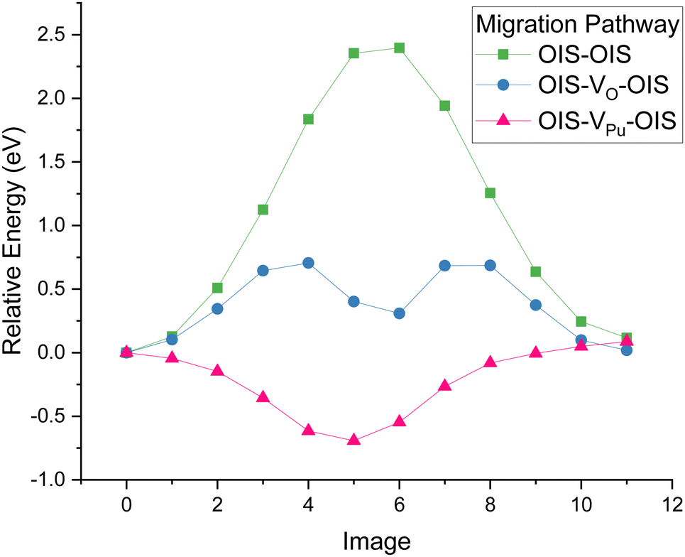 | ||
| Fig. 1 Relative energy barriers for different migration pathways for He to move between two interstitial sites in PuO2 from NEB calculations. A direct OIS–OIS hop (green squares) has the highest energy barrier, migrating via an oxygen vacancy (blue circles) has a much lower energy barrier and via a plutonium vacancy (pink triangles) there is a negative energy at the plutonium vacancy site, so this site may act as a trap for helium rather than a migration pathway. | ||
For the plutonium vacancy (VPu) assisted pathway, the VPu midpoint has the lowest energy, with a 0.7 eV energy barrier for the helium to then leave to an OIS. This suggests that if plutonium vacancies are present, helium diffusion could be reduced as the helium atoms will become trapped at VPu sites.
The work presented here is in line with studies on other actinide oxides. Oxygen vacancy assisted helium migration has been found to be the energetically favourable mechanism in UO2 with energy barriers comparable to this work.30,31,46,47 Under helium infusion conditions in UO2, in which vacancy concentrations are low, the atomic diffusion of helium has been found to be much slower than in radiation damaged materials,48,49 supporting the theory that helium migration is vacancy assisted.
3.3 Helium diffusion calculations
A fluorite PuO2 lattice with a helium concentration of 0.5 at% was constructed by randomly inserting He atoms into OISs. The system was evolved for 5 ns at 100 K intervals between 1000–3000 K. Fig. 2 plots the diffusivity of He, O and Pu calculated at each temperature. Three regions of interest (R1, R2 and R3) are highlighted. The lowest temperature region R1 (1000–1500 K) displays no diffusion. Here atoms only vibrate around their lattice sites over the simulation time scale.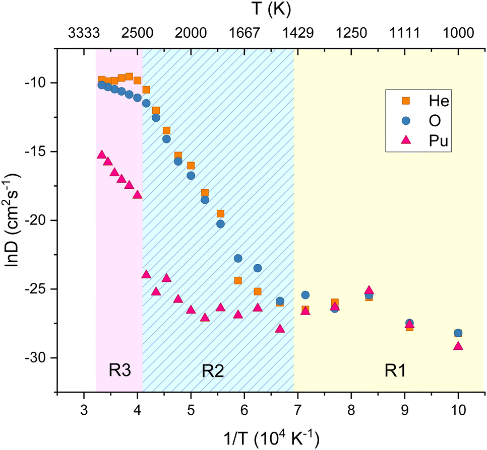 | ||
| Fig. 2 Diffusivity as a function of temperature for helium, oxygen and plutonium in PuO2. 0.5% He concentration, simulation evolved for 5 ns at every 100 K between 1000–3000 K. Helium and oxygen diffusivity are closely linked. Plutonium diffusion begins at approx. 2500 K. Three regions R1, R2 and R3 are highlighted which are explained in the text. | ||
In R2 the diffusivity of He and O increases with increasing temperature, with their diffusion closely aligned. This reinforces the NEB calculation findings of helium inter-site hopping via oxygen vacancies being energetically favourable and suggests the main helium diffusion mechanism is oxygen vacancy assisted. Above 2500 K (R3), the oxygen diffusion levels off which may be due to the temperature being roughly 0.8 Tm where it has been suggested that the oxygen sub lattice goes through a Bredig phase transition and becomes amorphous.33 Also in this region plutonium diffusivity increases. It is possible that the helium diffusivity plateau could be due to VPu sites becoming available and trapping helium. However, these temperatures are very close to the melting point of PuO2, so results must be treated with caution.
The MSD plots of He, O and Pu at a temperature from each region are included for reference in the ESI.† These simulations were repeated for larger supercell sizes of 10 × 10 × 10 and 12 × 12 × 12 and included in the ESI.† It was found that the fundamental features of helium diffusion in PuO2 are not affected by increased supercell size.
Systems with increasing helium concentrations were then generated. The percentage volume expansion as a function of the helium concentration at 298 K was calculated, as displayed in Fig. 3. The volume expansion as a function of helium concentration in UO246 and metallic Pu9 are also included in Fig. 3 for comparison. It can be seen that for PuO2, UO2 and Pu, a linear volume expansion with increasing helium concentration is predicted. The higher expansion coefficient for Pu metal can be related to the different structure for this.
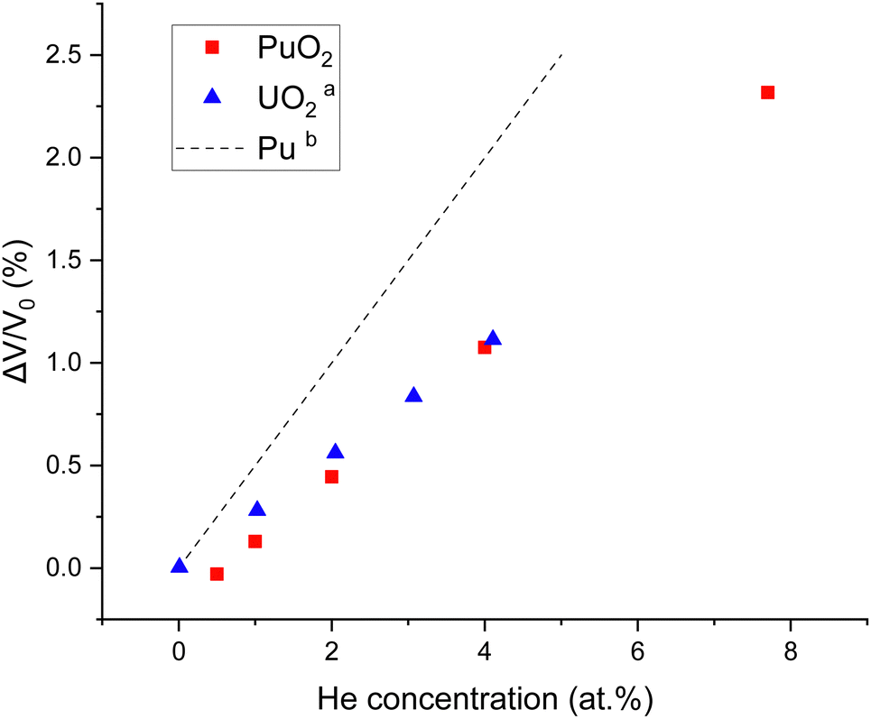 | ||
| Fig. 3 Percentage volume expansion as a function of the helium concentration in PuO2, UO2 and Pu. aYun et al.46bWolfer.9 Experiments show a typical volume expansion of 1% after large irradiation doses (Helen Steele, private communication) indicating a maximum He concentration of 5%. | ||
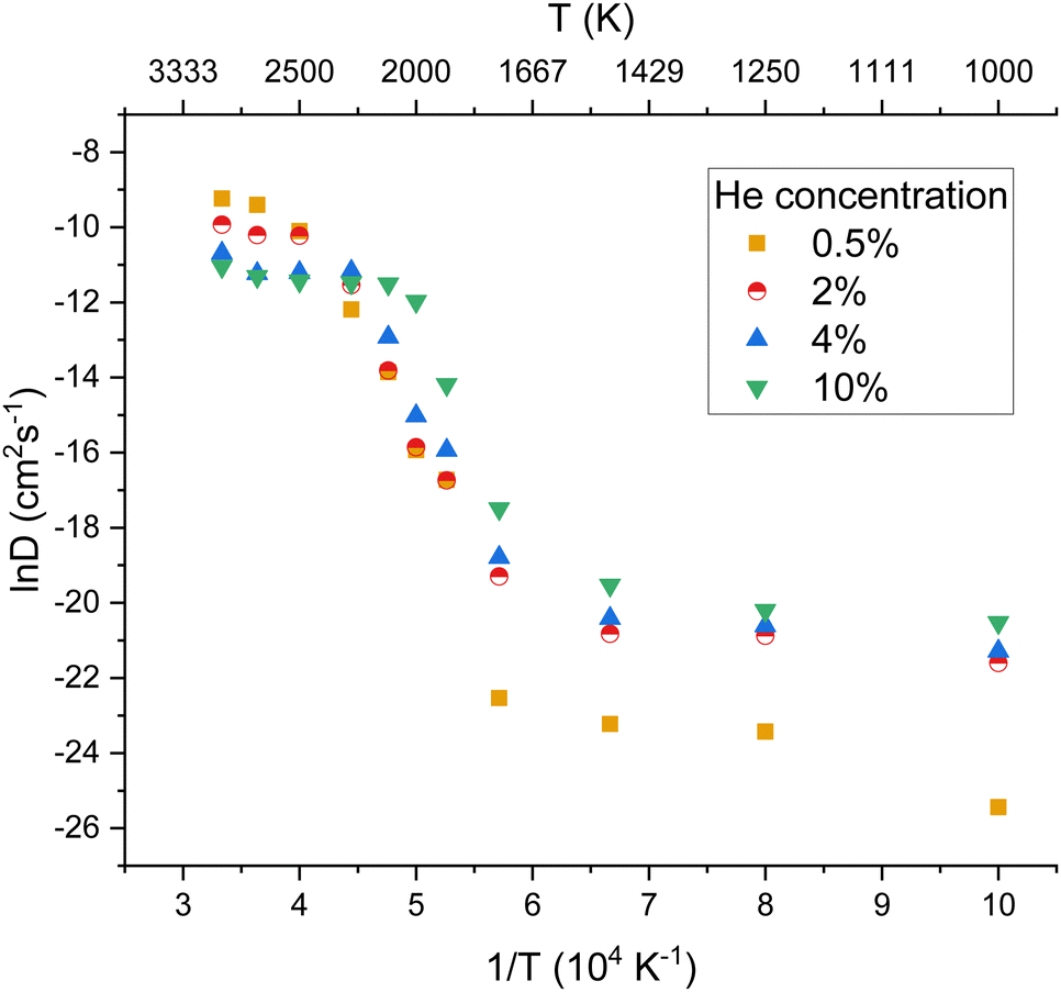
The diffusivity of helium in PuO2 lattices of varying helium concentrations is displayed by Fig. 4. Below 2000 K no notable distinction was found in helium diffusivity regardless of helium concentration. For all of the helium concentrations, the bounds of R1 remain roughly consistent. However R2 becomes much smaller for increasing concentrations. It can be seen that the plateau in helium diffusivity is reached at lower temperatures for higher helium concentrations; for 10% He the R3 begins at 2000 K. This is due to the higher helium concentrations enabling helium clusters to form at lower temperatures and helium trapped within a cluster being less mobile. In the lattice with 10% He, 15 clusters had formed at 2000 K. In contrast, no helium clusters had formed at 2000 K in the lattices with 2 and 4% He (see ESI†).
 | ||
| Fig. 4 The variation of helium diffusivity in PuO2 as a function of temperature for four different helium concentrations (0.5, 2, 4 and 10%). At low temperatures only vibration around lattice sites occurs; at ≈2000 K the diffusivity starts to increase with increasing temperature with the plateau region beginning at a lower temperature for higher He concentrations. D was calculated over a 1 ns time scale, as such the results are not in equilibrium as helium is still diffusing into clusters. | ||
The output of all simulations were inspected in OVITO42 with oxygen and plutonium vacancies visualised and helium trajectories plotted. In all cases helium atoms initially simply vibrated around their site until temperatures of 1500 K where inter-site hops occurred in the vicinity of an oxygen vacancy. Fig. 5(a) displays the trajectories of the He atoms in PuO2 with 2 at% He at 2100 K. A typical inter-site hop is shown in the circled green area and is analysed over a specific time period in Fig. 5(b). It can be clearly seen that the helium migration is aided by an oxygen vacancy. From our NEB calculations in Fig. 1 we see a 0.4 eV difference in energies between the OIS site and the VO site but an energy barrier of 0.7 eV OIS-VO and 0.3 eV VO-OIS. From the Arrhenius equation if we assume a prefactor of 1.0 × 10¹³, then at 1500 K we would expect a jump OIS-VO every 22 ps and OIS-VO every 1 ps on average. OIS–OIS would occur every 10 ms. Thus, movement both ways via the O-vacancy mechanism is possible over the time scale of our simulations.
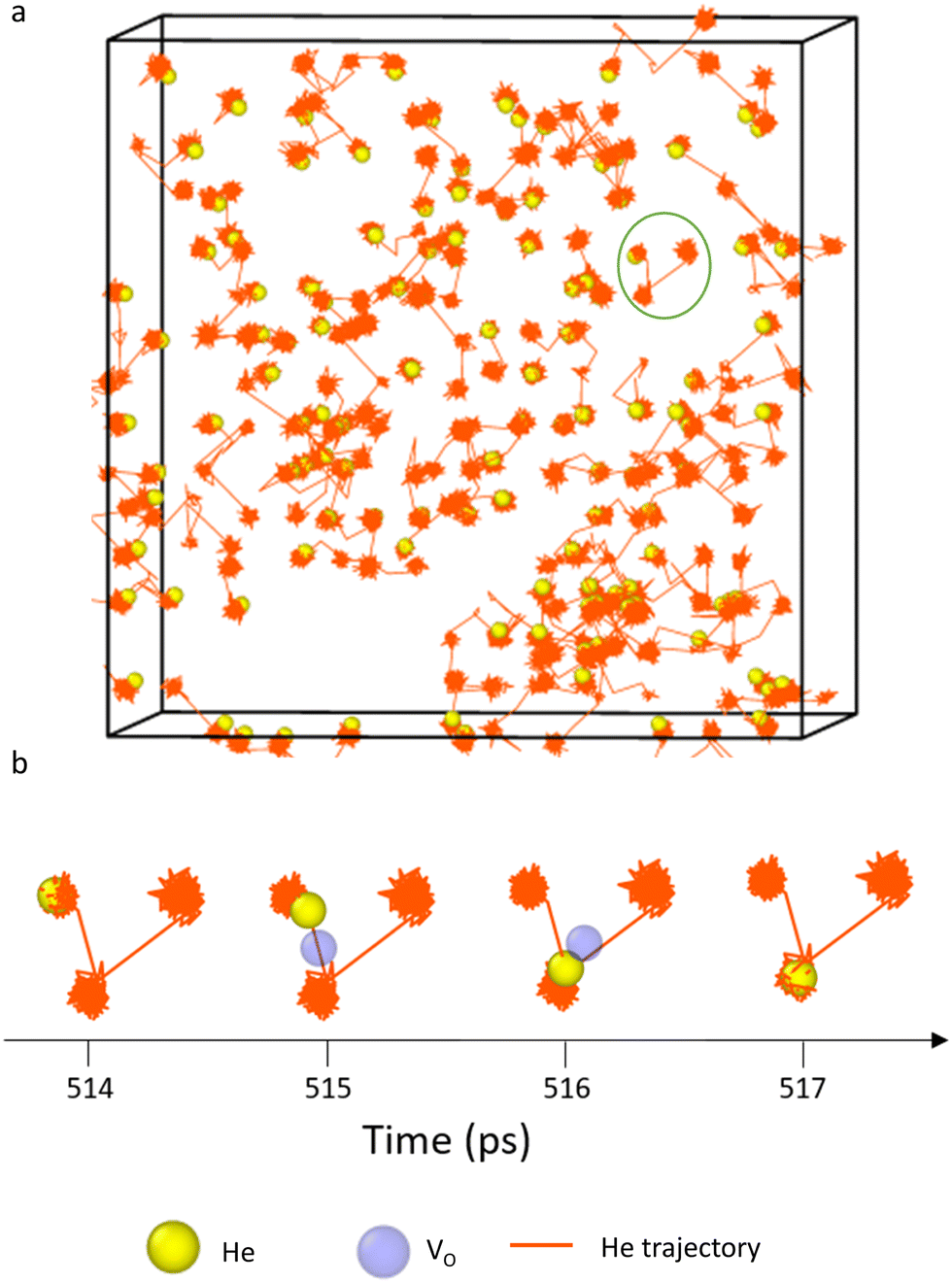 | ||
| Fig. 5 Trajectories of He atoms in initially defect-free PuO2 at 2100 K. (a) Displays the trajectory of all He atoms over a period of 1 ns. (b) Displays a snapshot of an inter-site hop by a He atom from the area circled in green in (a). The time period in (b) is 514–517 ps. It can be seen that at 515 ps an oxygen vacancy is generated in the vicinity of the helium and the helium uses this to migrate to a neighbouring OIS. | ||
The helium diffusion energy barrier in defect-free PuO2 was calculated to be 5.3 eV from the Arrhenius behaviour exhibited in R2 in Fig. 2. The value of 5.3 eV was surprising, since the barrier determined from NEB for the direct interstitial to interstitial hop was previous calculated as 2.4 eV. Further analysis of He diffusion at 2000 K showed that over 1 ns, 12 He hop events occurred of which 9 were via the O vacancy mechanism and 3 via the direct interstitial to interstitial hop. The barrier to displace an O atom into an interstitial site was calculated to be 6 eV and for the He atom to diffuse via the O vacancy mechanism another 0.6 eV is required. Thus the 5.3 eV barrier can be seen as an average from the different He diffusion mechanisms. This also implies that the attempt frequency for the direct interstitial to interstitial hop is several orders of magnitude smaller than that of a hop via an oxygen vacancy.
The simulations show that oxygen vacancy assisted He inter-site hopping is a dominant process in PuO2. Limited experimental data of helium diffusion in PuO2 is available, but some studies of oxygen diffusion in PuO2 exist.50,51 The relatively low defect energy of OFPs20,21 combined with the low diffusion barriers for O defects determined by Stan et al.52 indicates that these will be prevalent in the system, so will be available to assist helium migration. Oxygen vacancy assisted inter-site hopping has also been found to be the main diffusion mechanism of He in UO2.30,31,47
 | ||
| Fig. 6 Helium diffusivity as a function of temperature for four different Schottky defect concentrations in PuO2. The helium concentration was 2% with all helium atoms initially randomly inserted into OISs. One can see that He diffusion occurs even at low temperatures when Schottky defects are present. | ||
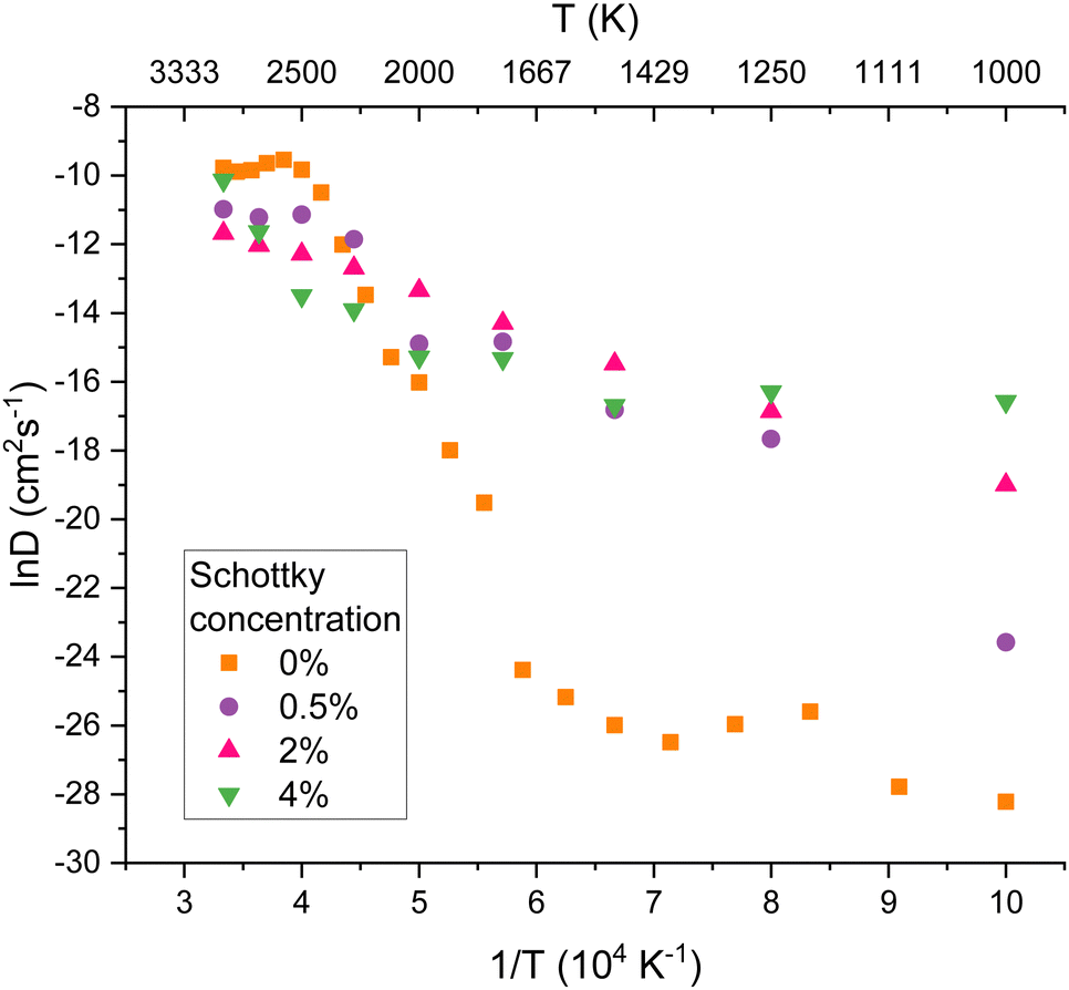
Helium diffusion energy barriers were calculated from the Arrhenius behaviour exhibited in R2 in Fig. 6. The Ea values calculated were 5.3, 1.7, 1.1 and 1.0 eV for Schottky concentrations of 0, 0.5, 2 and 4% respectively. From this it can be seen that there is a significant increase in He diffusion when O vacancies are initially present in the lattice, as the diffusion barriers are lowered. Although PuO2 is stored in the lower temperature regime (R1), vacancies will be naturally be present due to irradiation events so that He diffusion will occur at a faster rate than in the vacancy-free system.
The diffusivity of oxygen at the same Schottky concentrations was calculated and the results are plotted in Fig. 7. As found by Wang et al.,21 increases in defect concentrations significantly increase oxygen diffusivity. Comparing Fig. 6 and 7 it is evident that oxygen and helium diffusivity are similarly affected by the presence of defects.
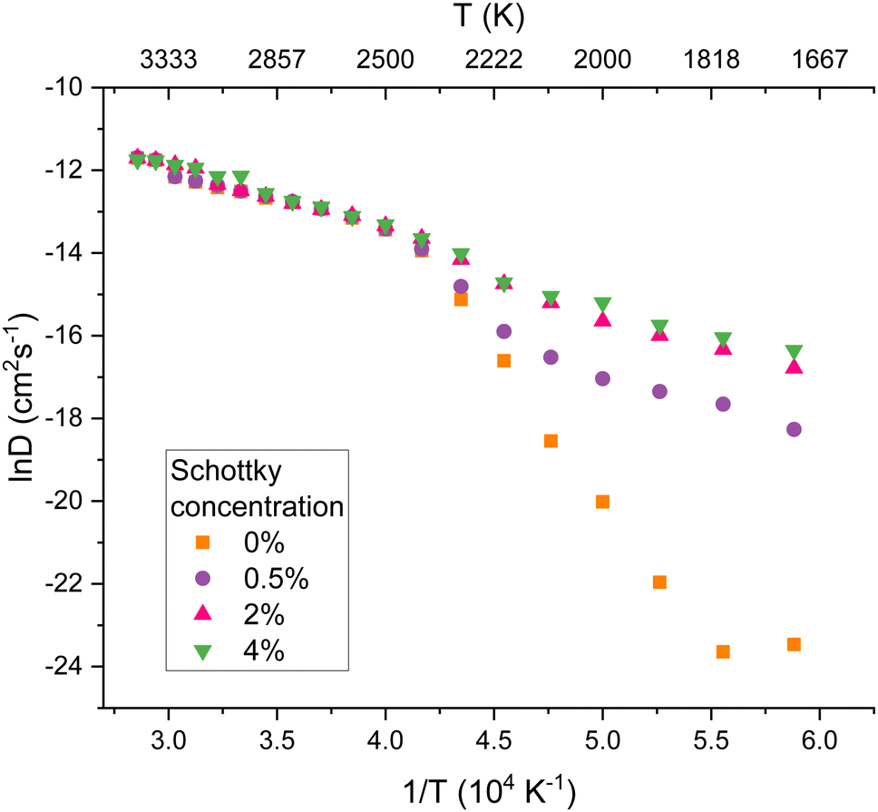 | ||
| Fig. 7 Oxygen diffusion coefficients as a function of temperature in PuO2 at four different Schottky defect concentrations. Below the phase change at approx. 2500 K the concentration of defects has a significant effect on oxygen diffusivity. In the superionic phase, the diffusivity of oxygen is the same for all Schottky concentrations, as at these temperatures the oxygen sublattice is amorphous. | ||
The diffusion of helium in PuO2 can be compared to existing studies of oxygen behaviour in UO2. There is a correspondence to the three regimes defined by Günay.53 Firstly, Günay53 defines the extrinsic region (1200–1750 K) where diffusion is assisted by irradiation induced defects. Günay53 then defines the intrinsic region (1800–2600 K), in which diffusion is due to the thermal energy results; here the lattice energy is high enough for dynamic Frenkel defects to frequently form and recombine. The intrinsic region corresponds to the R2 region defined earlier in this work, suggesting that at temperatures where oxygen Frenkel pairs are being generated, these assist in helium migration. In this region in Fig. 6 it can be seen that when defects are already present in the lattice, standard Arrhenius behaviour is exhibited, as vacancies are already present to assist mobility. Finally, Günay53 defines the superionic region (2600–3200 K) in which the Bredig transition and melting takes place. Above this temperature the oxygen sublattice totally melts and behaves like a liquid with the uranium sublattice remaining solid. It can be seen that in this R3 region for all Schottky concentrations in Fig. 7 the oxygen diffusivity is the same.
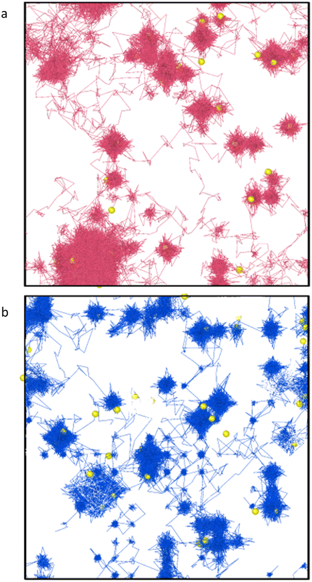 | ||
| Fig. 8 Trajectory of helium atoms in PuO2 with a 2% Schottky defect concentration at 2250 K over 1 ns. (a) Displays the trajectory when the helium atoms started in VPu sites (pink lines) and (b) when the helium started in VO sites (blue lines). There is much less interstitial site hopping when helium atoms are input at plutonium vacancies. | ||
To further understand He behaviour at VPu sites without the influence of VO defects, a cell containing PuFPs was constructed with the He atoms starting at the VPu sites. MD was run for 1 ns. It was found that all of the He atoms had migrated to OISs and very few VPu sites remained due to the Pu Frenkel pairs recombining and Pu interstitials displacing He atoms from their VPu sites. The energetic benefit of a single helium being in the Pu vacancy was thus outweighed by the drive for Pu Frenkel pairs to recombine, as the defect energy of a PuFP is high.16,18,20,21
Next, a lattice was generated that contained 0.5% randomly distributed Pu vacancies with no respective interstitials. Two initial configurations were modelled: He input at OISs and He input at VPu sites.
Fig. 9 illustrates the trajectories of the He atoms during three time intervals for both starting configurations. In the first 300 ps, He atoms at VPus oscillate around the vacancy sites, whereas for He atoms at OISs there is some interstitial hopping. During the second interval (300–600 ps) the He at VPus continue to oscillate and some oxygen vacancies are generated surrounding some of the Pu vacancies. The OIS start system shows lots of interstitial site hopping and high levels of diffusion, with lots of the helium atoms migrating to the plutonium vacancies. The final time period shows similar behaviour for both simulations, i.e. the He atoms are located at the VPu sites. This indicates that helium will always diffuse to plutonium vacancies if they are available.
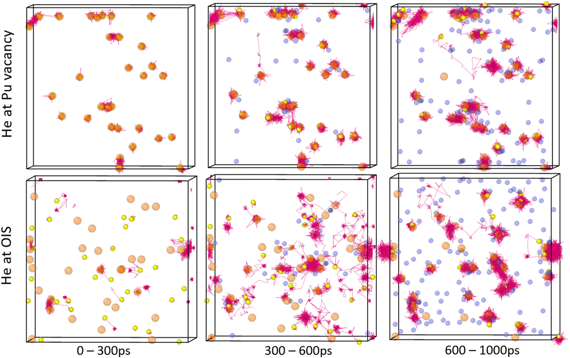 | ||
| Fig. 9 Trajectory of helium atoms in PuO2 with 0.5% plutonium vacancies at 2250 K. The 1 ns simulation is split into three time periods. The top row illustrates the trajectory when He is input at VPu sites and the bottom row when He is input at OISs. Helium (yellow spheres) trajectory is represented by pink lines, oxygen vacancies by blue spheres and plutonium vacancies by pink spheres. 0–300 ps is the equilibration period. 300–600 ps in OIS input system shows He with high mobility. 600–1000 ps shows He at Pu vacancy sites. | ||
In both final states, all helium atoms are in the vicinity of VPu sites. For the He input at VPus, only four migrate from their initial site to a different VPu with the rest remaining trapped. For He input at OISs, every helium atom migrates from its initial site. In both cases no helium atoms occupy VO, the VO were used in OIS-VO-OIS pathways for He migration.
Govers et al.31 found that in UO2, when the lattice contains just uranium vacancy defects, He diffusion is greatly decreased when a He is input at a VUversus at an OIS. However, the simulations were run for 25 ps, so it is suggested that the duration was insufficient for the He to migrate from the OISs to the VU sites.
3.4 Helium clustering
This section is composed of three computational methods used to investigate He clustering.:vacancy ratio. Three seed sizes were chosen: 1 Schottky, 2 Schottkies and 4 Schottkies which contain 3, 6 and 12 vacancies respectively.
For each HenVm cluster, there are many potential configurations for the n He atoms. An iterative procedure was followed to find the lowest energy and therefore most stable configuration. The procedure consisted of two minimisation steps: helium atoms were added to the vacancy and the system was evolved via damped MD. Next, the helium atoms were randomly displaced and the lattice was minimised again using the conjugate gradient method. For the situations where the helium atoms remained clustered in the vacancy, the minimum energy was recorded.
By following this procedure at least 10 configurations for each He:vacancy ratio were trialled.
The average trapping energy was then calculated for each He:vacancy ratio. The trapping energies, ET, were calculated relative to the incorporation energy value obtained for an OIS as follows:
 | (3) |
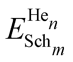 is the energy of n He atoms clustered at m Schottky trios, EHeOIS is the incorporation energy of one He at an OIS and ESch is the defect energy of an isolated Schottky trio. A negative ET value indicates an energy decrease of the system when He moves from an OIS to the cluster. A positive value means that energy is required to incorporate He at the cluster.
As seen by Fig. 10, for all three seed sizes considered, a similar trend is found. The trapping energy rapidly reduces in magnitude up to a He:vacancy ratio of approximately 0.5:1. Clusters with ratios larger than this size have a steady addition energy rate. The trapping energies are negative so there is an energetic drive for the helium atom to join the cluster rather than to remain isolated in the lattice. At ratios greater than ∼3.5:1, no stable configurations could be found; the helium atoms would always leave the cluster upon minimisation.
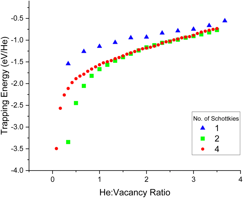 | ||
| Fig. 10 Trapping energies of He atoms at Schottky void sites as a function of a cluster's He:vacancy ratio. A more negative trapping energy means a more energetically favourable site for helium to occupy. Three seed locations for the clusters were considered, made of 1, 2 and 4 Schottky defect clusters. | ||
The successive incorporation energy for each He addition to a cluster was also calculated. The energy of incorporation of a single He in an OIS was found to be 1.7 eV, so when the addition of He to a cluster is greater than this value, it would be more energetically favourable for the helium to remain at an isolated site rather than join the cluster. As shown by Fig. 11 it was found that for all three Schottky sizes, the point at which the successive He addition energy exceeds that of 1.7 eV (orange line on plot) was when the ratio is roughly 3.5 helium atoms per vacancy. In metallic Pu, Ao et al.54 found the maximum n/m ratio in a HenVm cluster to be 6:1 and the most energetically stable ratio to be 1:1.55 Robinson et al.56 found the maximum He:vacancy ratio to be 2:1 in Ga stabilised Pu.
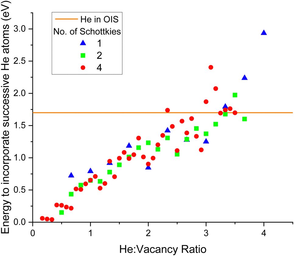 | ||
| Fig. 11 Energy to incorporate successive He atoms at Schottky void sites as a function of the cluster's He:vacancy ratio. The orange straight line at 1.7 eV is the energy to incorporate He at an isolated OIS. When the incorporation energy is greater than this line it is less favourable for an additional He to join the cluster than to exist in isolation at an OIS. | ||
The difference in energy barriers, ΔEb, between joining and leaving a cluster was calculated by:
| ΔEb = Ejoin − Eleave. | (4) |
A negative value for ΔEb means more energy is required for a He interstitial to join a cluster than to leave it. The point at which ΔEb becomes negative is the point at which the maximum energetically favourable He:vacancy ratio has been found.
As displayed by Fig. 12, the same trend was found for all three Schottky seed sizes; as the He:vacancy ratio increases, ΔEb decreases. At low He:vacancy ratios the energy to join is lower than the energy to leave, so it is energetically favourable for helium atoms to join the cluster. However, when the He:vacancy ratio exceeds ∼3.5:1, the opposite is true ΔEb becomes negative, indicating that it now requires more energy for a He atom to join the cluster than to leave it, so this is the size at which the clusters are no longer energetically favourable.
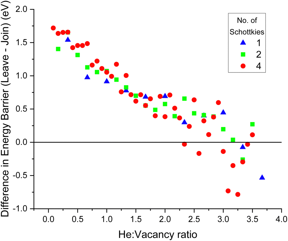 | ||
| Fig. 12 Difference in energy barriers for a He interstitial to join and leave a cluster as a function of a cluster's He:vacancy ratio. When the energy difference becomes negative, it requires more energy for helium to join the cluster than to leave it, so the maximum energetically favourable He:vacancy ratio is at this point. Three Schottky seed location sizes were considered (1, 2 and 4 Schottkies) and the maximum stable He:vacancy ratio was ∼3.5:1. | ||
:vacancy ratios of the generated clusters. The helium concentrations chosen were 0.5, 1, 2, 4, 7.7 and 14.3 at%. Helium interstitials were randomly distributed in OISs throughout the lattice. The temperature of the system was set at 2250 K and the system was evolved for 5 ns, with cluster analysis performed at 1 and 5 ns.
Table 1 displays the cluster analysis results at 1 and 5 ns. It can be seen that no large clusters were formed within the simulation time until the helium concentration was 2%. For the lattice containing 2 at% He, at 1 ns one large cluster had formed (containing 10 He), this cluster grew dramatically over the next 4 ns so that at 5 ns it contained 68 He atoms. For He concentrations above 2%, the number of clusters decreased during the 1 ns to 5 ns time period, showing that the clusters were merging to form fewer, larger clusters.
| He at% | No. large clusters | Max cluster size (no. He) | ||
|---|---|---|---|---|
| 1 ns | 5 ns | 1 ns | 5 ns | |
| 0.5 | 0 | 0 | 1 | 1 |
| 1 | 0 | 0 | 1 | 1 |
| 2 | 1 | 2 | 10 | 68 |
| 4 | 7 | 3 | 40 | 202 |
| 7.7 | 12 | 7 | 101 | 342 |
| 14.3 | 19 | 1 | 240 | 1015 |
Fig. 13 plots the evolution of the simulation as a function of the number of helium clusters and number of vacancies present in the lattice for the He concentration of 4%. The number of clusters at 0 ns is 250, as there are 250 He atoms in the simulation sufficiently separated that they count as isolated. It can be seen that the number of helium clusters plateaus at roughly 3 ns, indicating that a steady state has been reached.
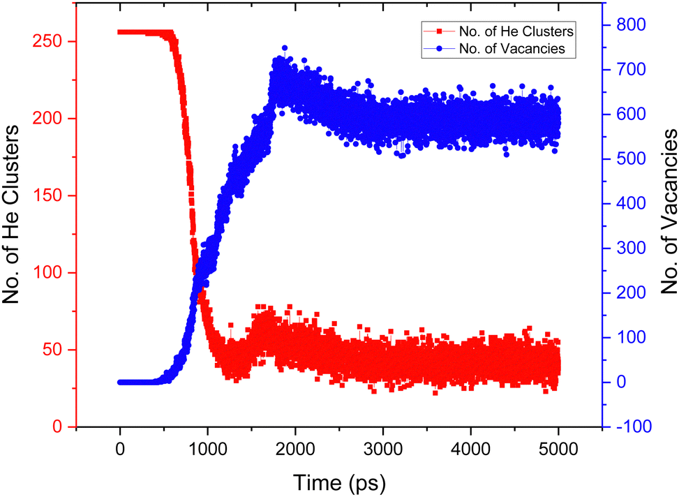 | ||
| Fig. 13 The number of helium clusters (left y-axis, red) and the number of Pu and O vacancies (right y-axis, blue) as a function of time. The simulation was of PuO2 at 2250 K with a 4% He concentration. As the number of vacancies increases, the number of clusters decreases, as more helium atoms are joining clusters so the overall number decreases as there are fewer, bigger helium clusters. After 3000 ps a stable state of the number of He clusters and lattice vacancies is established. | ||
Next, the He:vacancy ratios of the large He clusters identified in Table 1 were calculated. Fig. 14 displays a histogram of the cluster ratios formed for each helium concentration. As seen in Fig. 14(a) the most frequent He:vacancy ratio formed after 1 ns is 0.7:1 and the maximum is 2:1. After 5 ns (Fig. 14(b)) the mode is lower, at 0.5:1. There are fewer clusters in total, with overall lower He:vacancy ratios, indicating that clusters have merged to form clusters with a more stable (lower) He:vacancy ratio. As evident from Fig. 12, the number of clusters becomes stable after approximately 3 ns, so it is likely that this is the point at which the clusters with lower He:vacancy ratios have formed.
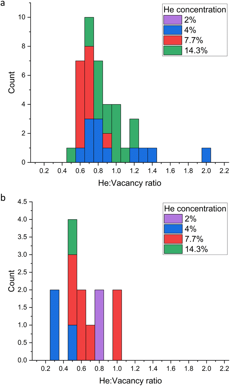 | ||
| Fig. 14 Histogram of the He:vacancy ratio of large (≥9 He) clusters that formed after a time period of (a) 1 ns and (b) 5 ns for different helium concentrations in PuO2 with 2% Schottky concentration. (a) After 1 ns at the lowest He concentration (2% He) no large clusters had formed. The most common He:vacancy ratio was 0.7:1. (b) After the system was evolved for 5 ns, large clusters had formed for all helium concentrations. The most common He:vacancy ratio was 0.5:1. The number of clusters is significantly reduced as smaller clusters have merged together. | ||
The systems studied here initially contained no defects which will not be the case in reactor generated PuO2, where intrinsic defects will be present as a result of radiation damage. These will act as seed locations for He clusters with the oxygen vacancies aiding He mobility.
Fig. 15 displays a system with a 4% He concentration and three Schottky trios input at the centre at 2250 K. The figure illustrates the helium clusters present at different time stamps. He cluster formation can be seen around the initial input defect but additional clusters form elsewhere. Upon inspection it was found that Pu was less stable in the lattice when next to O vacancies. Temporary PuFPs could be formed allowing a helium atom to occupy a VPu. Alternatively, instead of the He atom being ejected by recombining Pu (as is the case with a single He atom), when the number of helium atoms close to a VPu was three or more, the PuFP no longer recombines and a Schottky defect is formed. An example of this is the He6V4 cluster identified at 650 ps in Fig. 15. Thus, a high local He concentration itself can generate defects after which the cluster becomes immobile.
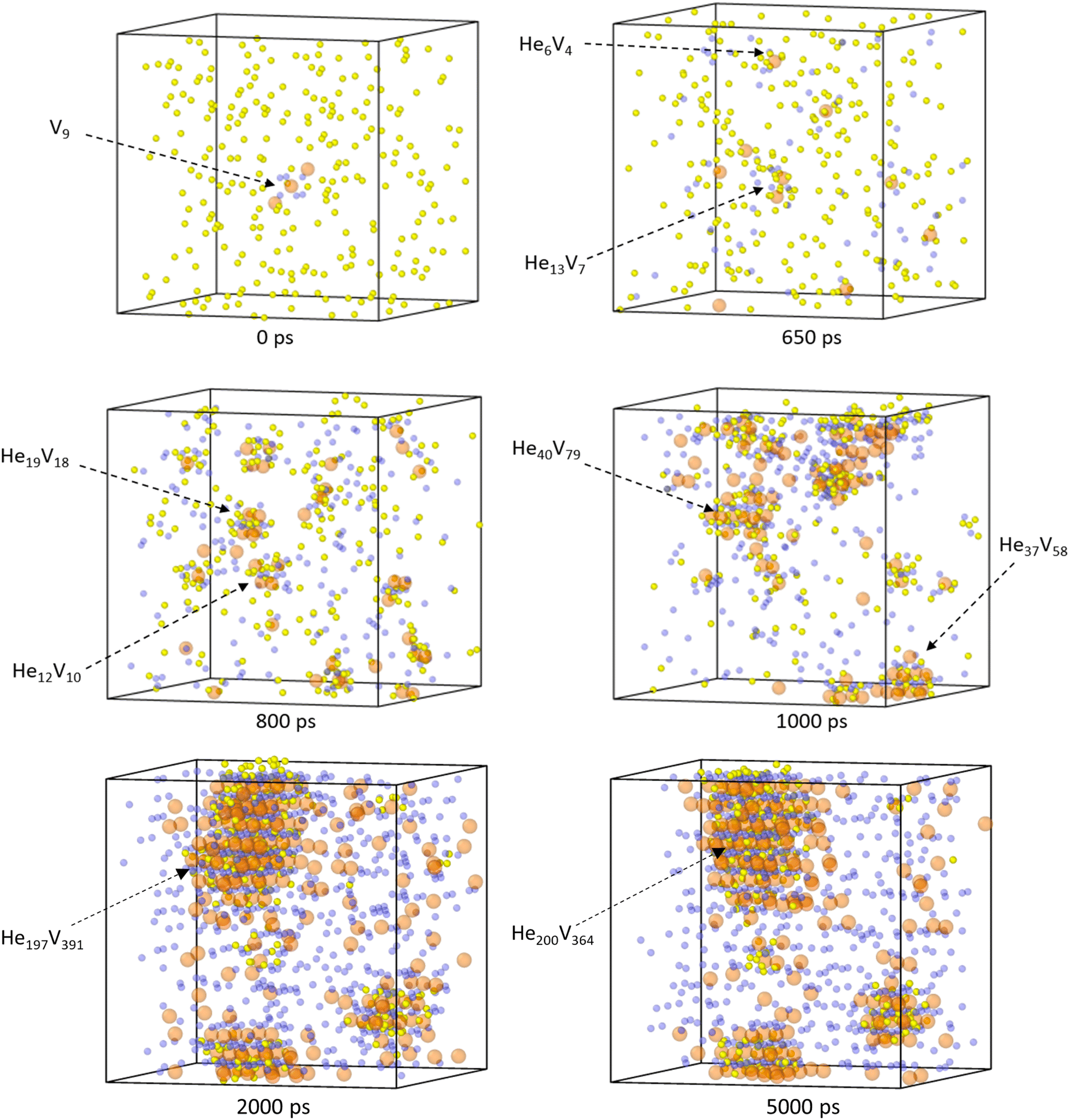 | ||
| Fig. 15 PuO2 supercell with 4% He concentration at 2250 K. Initially three Schottky trios (VPu pink spheres, VO blue spheres) were input in the centre of the lattice with the He atoms (yellow spheres) randomly inserted in OISs. Cluster formation shown at different times and the He:vacancy ratios labelled. | ||
From Fig. 15 we find that initially helium clusters form with high He:vacancy ratios, after which more vacancies are formed, the clusters coalesce and the He:vacancy ratios reduce. It can be seen that at 2000 ps a very large cluster has formed and remains intact throughout the rest of the simulation.
4 Conclusions
We have determined that in defect free PuO2, helium exhibits limited diffusive behaviour until the temperature exceeds 1500 K. Helium diffusion under 1500 K will occur but by rare events which take place over longer timescales than those considered in this work. However, we have found that when vacancies are present within the lattice, the helium diffusion energy barrier is significantly reduced and helium atoms exhibit diffusive behaviour at lower temperatures. Therefore whilst the storage of PuO2 will be at temperatures well below 1500 K, due to the presence of defects within the lattice we suggest that helium will be mobile in PuO2 under conditions relevant to storage.The main helium diffusion mechanism proposed is oxygen vacancy assisted inter-site hops with helium and oxygen having comparable diffusion rates. Plutonium vacancies have been found to act as traps for helium, significantly reducing helium diffusion.
The diffusion barriers calculated in this work are of a similar order of those found for He diffusion in UO2.31 We suggest that a main factor governing He diffusion in nuclear materials is the level of damage present in the lattice, with oxygen vacancies dramatically increasing He diffusion rates. As PuO2 has higher radioactivity which leads to higher rates of self-irradiation damage, it would be expected that there would be higher rates of He diffusion in PuO2 than in UO2.
We have demonstrated the growth of large helium clusters in PuO2. The highest energetically stable helium to vacancy ratio of a cluster was calculated via multiple methods to be ∼3.5:1. Above which it requires more energy for helium to join a cluster than to leave it. From the average helium to vacancy ratio of the clusters generated in this work, we predict that helium clusters with helium to vacancy ratios less than 1:1 will form in PuO2 during storage.
Finally, it has been found that helium occupation of a plutonium vacancy does not prevent plutonium Frenkel pair recombination until at least three He occupy the site. At such point the site acts as a seed location for a He cluster, via the formation of a Schottky trio.
Conflicts of interest
There are no conflicts of interest to declare.Acknowledgements
The computations described in this paper were performed using the University of Birmingham's BlueBEAR HPC service, which provides a High Performance Computing service to the University's research community. This project was funded by the Nuclear Decommissioning Authority and carried out as part of the EPSRC's TRANSCEND project (EP/S01019X/1).Notes and references
- IAEA, The Potential Role of Nuclear Energy in National Climate Change Mitigation Strategies, 1984, 2021.
- BEIS, Net Zero Strategy: Build Back Greener, 2021.
- Nuclear Decommissioning Authority, Progress on Plutonium Consolidation, Storage and Disposition, 2019.
- N. C. Hyatt, Energy Policy, 2017, 101, 303–309 CrossRef.
- N. C. Hyatt, npj Mater. Degrad., 2020, 4, 28 CrossRef CAS.
- H. E. Sims, K. J. Webb, J. Brown, D. Morris and R. J. Taylor, J. Nucl. Mater., 2013, 437, 359–364 CrossRef CAS.
- J. F. Ziegler, M. D. Ziegler and J. P. Biersack, Nucl. Instrum. Methods Phys. Res., Sect. B, 2010, 268, 1818–1823 CrossRef CAS.
- H. Balboa, L. Van Brutzel, A. Chartier and Y. Le Bouar, J. Nucl. Mater., 2018, 512, 440–449 CrossRef CAS.
- W. G. Wolfer, Los Alamos Sci., 2000, 26, 274–285 CAS.
- M. H. Rand, A. C. Fox and R. S. Street, Nature, 1962, 195, 567–568 CrossRef CAS.
- R. B. Roof, Adv. X-Ray Anal., 1972, 16, 396–400 CrossRef.
- T. D. Chikalla and R. P. Turcotte, Radiat. Eff. Defects Solids, 1973, 19, 93–98 CrossRef CAS.
- M. Noe and J. Fuger, Inorg. Nucl. Chem. Lett., 1974, 10, 7–19 CrossRef CAS.
- W. D. Neilson, J. T. Pegg, H. Steele and S. T. Murphy, Phys. Chem. Chem. Phys., 2021, 23, 4544–4554 RSC.
- Y. Lu, Y. Yang and P. Zhang, J. Alloys Compd., 2015, 649, 544–552 CrossRef CAS.
- X. Tian, T. Gao, C. Lu, J. Shang and H. Xiao, Eur. Phys. J. B, 2013, 86, 179 CrossRef.
- P. Tiwary, A. van de Walle, B. Jeon and N. Grønbech-Jensen, Phys. Rev. B: Condens. Matter Mater. Phys., 2011, 83, 094104 CrossRef.
- M. Freyss, N. Vergnet and T. Petit, J. Nucl. Mater., 2006, 352, 144–150 CrossRef CAS.
- S. C. Hernandez and E. F. Holby, J. Phys. Chem. C, 2016, 120, 13095–13102 CrossRef CAS.
- M. S. Read, S. R. Walker and R. A. Jackson, J. Nucl. Mater., 2014, 448, 20–25 CrossRef CAS.
- L.-F. Wang, B. Sun, H.-F. Liu, D.-Y. Lin and H.-F. Song, J. Nucl. Mater., 2019, 526, 151762 CrossRef CAS.
- W. D. Neilson, H. Steele, N. Kaltsoyannis and S. T. Murphy, Phys. Chem. Chem. Phys., 2022, 24, 8245–8250 RSC.
- T. G. Zocco, Los Alamos Sci., 2000, 26, 286–289 CAS.
- B. Ao, P. Chen, P. Shi, X. Wang, W. Hu and L. Wang, Commun. Comput. Phys., 2012, 11, 1205–1225 CrossRef.
- K. Katsuyama, A. Ishimi, K. Maeda, T. Nagamine and T. Asaga, J. Nucl. Mater., 2010, 401, 86–90 CrossRef CAS.
- D. Roudil, X. Deschanels, P. Trocellier, C. Jégou, S. Peuget and J.-M. Bart, J. Nucl. Mater., 2004, 325, 148–158 CrossRef CAS.
- H. Ullmaier, P. Ehrhart, P. Jung and H. Schultz, Atomic Defects in Metals/Atomare Fehlstellen in Metallen, Springer Berlin, Heidelberg, 1991 Search PubMed.
- Y. Pipon, C. Raepsaet, D. Roudil and H. Khodja, Nucl. Instrum. Methods Phys. Res., Sect. B, 2009, 267, 2250–2254 CrossRef CAS.
- C. Ronchi and J. P. Hiernaut, J. Nucl. Mater., 2004, 325, 1–12 CrossRef CAS.
- E. Yakub, C. Ronchi and D. Staicu, J. Nucl. Mater., 2010, 400, 189–195 CrossRef CAS.
- K. Govers, S. Lemehov, M. Hou and M. Verwerft, J. Nucl. Mater., 2009, 395, 131–139 CrossRef CAS.
- M. W. D. Cooper, M. J. D. Rushton and R. W. Grimes, J. Condens. Matter Phys., 2014, 26, 105401 CrossRef CAS PubMed.
- M. W. D. Cooper, S. T. Murphy, M. J. D. Rushton and R. W. Grimes, J. Nucl. Mater., 2015, 461, 206–214 CrossRef CAS.
- R. A. Aziz, A. R. Janzen and M. R. Moldover, Phys. Rev. Lett., 1995, 74, 1586–1589 CrossRef CAS PubMed.
- D. C. Parfitt and R. W. Grimes, J. Nucl. Mater., 2008, 381, 216–222 CrossRef CAS.
- J. F. Ziegler and J. P. Biersack, The Stopping and Range of Ions in Matter, Springer, US, Boston, MA, 1985, pp. 93–129 Search PubMed.
- A. P. Thompson, H. M. Aktulga, R. Berger, D. S. Bolintineanu, W. M. Brown, P. S. Crozier, P. J. in’t Veld, A. Kohlmeyer, S. G. Moore, T. D. Nguyen, R. Shan, M. J. Stevens, J. Tranchida, C. Trott and S. J. Plimpton, Comput. Phys. Commun., 2022, 271, 108171 CrossRef CAS.
- E. Bitzek, P. Koskinen, F. Gähler, M. Moseler and P. Gumbsch, Phys. Rev. Lett., 2006, 97, 170201 CrossRef PubMed.
- N. A. Zarkevich and D. D. Johnson, J. Chem. Phys., 2015, 142, 024106 CrossRef PubMed.
- B. D. Todd and P. J. Daivis, Nonequilibrium Molecular Dynamics: Theory, Algorithms and Applications, Cambridge University Press, 2017, pp. 150–202 Search PubMed.
- H. Mehrer, Diffusion in Solids, Springer, 2007 Search PubMed.
- A. Stukowski, Modell. Simul. Mater. Sci. Eng., 2010, 18, 015012 CrossRef.
- E. Murray, N. Palmer, W. Neilson, R. Jackson, M. Read, H. Steele and R. Orr, Proceedings of the WM Symposia, 2022, 22512 Search PubMed.
- T. Petit, M. Freyss, P. Garcia, P. Martin, M. Ripert, J.-P. Crocombette and F. Jollet, J. Nucl. Mater., 2003, 320, 133–137 CrossRef CAS.
- N. Kuganathan, P. Ghosh, A. Arya and R. Grimes, J. Nucl. Mater., 2018, 507, 288–296 CrossRef CAS.
- Y. Yun, O. Eriksson and P. M. Oppeneer, J. Nucl. Mater., 2009, 385, 510–516 CrossRef CAS.
- X.-Y. Liu and D. Andersson, J. Nucl. Mater., 2018, 498, 373–377 CrossRef CAS.
- F. Rufeh, D. R. Olander and T. H. Pigford, Nucl. Sci. Eng., 1965, 23, 335–338 CrossRef CAS.
- K. Nakajima, H. Serizawa, N. Shirasu, Y. Haga and Y. Arai, J. Nucl. Mater., 2011, 419, 272–280 CrossRef CAS.
- R. Deaton and C. Wiedenheft, J. Inorg. Nucl. Chem., 1973, 35, 649–650 CrossRef CAS.
- A. Bayoglu, A. Giordano and R. Lorenzelli, J. Nucl. Mater., 1983, 113, 71–74 CrossRef CAS.
- M. Stan and P. Cristea, J. Nucl. Mater., 2005, 344, 213–218 CrossRef CAS.
- S. D. Günay, High Temp. Mater. Processes, 2016, 35, 981–987 Search PubMed.
- B. Ao, X. Wang, W. Hu and J. Yang, J. Nucl. Mater., 2009, 385, 75–78 CrossRef CAS.
- B. Ao, P. Chen, P. Shi, X. Wang, W. Hu and L. Wang, Commun. Comput. Phys., 2012, 11, 1205–1225 CrossRef.
- M. Robinson, S. Kenny, R. Smith and M. Storr, J. Nucl. Mater., 2014, 444, 493–500 CrossRef CAS.
Footnote |
| † Electronic supplementary information (ESI) available. See DOI: https://doi.org/10.1039/d2cp02244c |
| This journal is © the Owner Societies 2022 |