
 Open Access Article
 This Open Access Article is licensed under a
 Creative Commons Attribution 3.0 Unported Licence
Ion transport mechanism in anhydrous lithium thiocyanate LiSCN part III: charge carrier interactions in the premelting regime
Markus
Joos
 a,
Maurice
Conrad†
b,
Sebastian
Bette
ab,
Rotraut
Merkle
*a,
Robert E.
Dinnebier
a,
Thomas
Schleid
b and
Joachim
Maier
a
a,
Maurice
Conrad†
b,
Sebastian
Bette
ab,
Rotraut
Merkle
*a,
Robert E.
Dinnebier
a,
Thomas
Schleid
b and
Joachim
Maier
a
aMax Planck Institute for Solid State Research, Heisenbergstr. 1, 70569 Stuttgart, Germany. E-mail: r.merkle@fkf.mpg.de
bInstitut für Anorganische Chemie, University of Stuttgart, Pfaffenwaldring 55, 70569 Stuttgart, Germany
First published on 27th July 2022
Abstract
In lithium thiocyanate Li(SCN), the temperature regime below the melting point (274 °C) is characterized by excess conductivities over the usual Arrhenius behavior (premelting regime). Here, the Schottky defect pair concentration is high, and the point defect chemistry can no longer be considered as dilute. Coulomb interactions of Schottky pairs are expected to occur lowering the formation energy of new carriers and hence leading avalanche-like to a transition into a fully defective superionic state. The respective non-linear behavior is investigated using the cube-root law approach characterized by a defect interaction parameter J, which is a measure of the effective defect-lattice energy. In the case of Li(SCN), the rather pronounced volume expansion is to be included in the model. A literature comparison with other materials emphasizes to what degree defect formation as well as defect interactions depend not only on the dominant mobile defect, but also on the respective sublattice. Overall, a quantitative description of the defect chemistry of Li(SCN) in the premelting regime is derived.
Introduction
It was shown that anhydrous Li(SCN) is Schottky disordered with lithium vacancies as mobile charge carriers.1 Their mobility is affected by slow reorientation processes in the (SCN)− anion sublattice.2 These findings explain ionic conductivities and their dependencies on doping and (impedance) frequency in the temperature range from 25 to 250 °C, provided that also trapping effects of the dopants are taken account of. In this temperature range the defect concentrations are still relatively low and the system can be regarded as dilute. Here, we investigate the defect chemistry above 250 °C close to the melting point (m.p.) of Li(SCN) in the so-called premelting regime, as well as beyond the melting point.
In literature, one can find many examples of anomalous (nonlinear) behavior close to a transition or melting point for various properties (conductivity,3–10 volume,11,12 strain,12 spin-lattice relaxation,13,14 and others15,16). In regard to conductivity, this is manifested as a nonlinear increase in the Arrhenius behavior, i.e. an excess conductivity. For AgBr,3 Schmalzried attributed the excess conductivity to an increase of mobile defect concentration and mobility caused by the volume thermal expansion. Later investigations, however, indicated that volume changes cannot fully explain the increase in conductivity.4 Since defect concentrations are high near a transition, dilute theories (e.g. Debye–Hückel) are not well suited to explain the interactions of defects in this regime.
Therefore, Hainovsky and Maier derived an approach which describes this interaction by a Madelung energy of oppositely charged defects. This leads to a Coulombic stabilization of the system expressed by an interaction parameter J.4,17,18 This is applicable in particular for high defect concentrations, and results in a cube-root law (the excess free enthalpy scales with the cube-root of defect concentration). Since the free enthalpy of defect formation decreases, it results in an avalanche-like defect formation termed superionic transition. This transition occurs in a certain temperature range just below the actual phase transition (structural or melting). Within the cube-root model, a critical temperature can be defined at which the steepest increase of defect concentration occurs.4 Phenomenologically, a related onset temperature of the superionic transition can be determined from linear extrapolations of the low and high temperature regimes in the conductivity Arrhenius plot.
This model of defect interactions allows one to clearly distinguish the superionic state from the defective state, as illustrated in Fig. 1. A crystal can be defect-free at zero absolute temperature. Above 0 K the defect concentrations increase with temperature but the absolute defect concentrations remain small. This weakly defective state is characterized by a high defect formation enthalpy (energy gap between perfect and excited state, e.g. regular and interstitial site). This energy requirement decreases with increasing defect concentration (heavily defective) owing to the mutual Coulombic stabilization of the charged ionic defects. In the curve of defect formation free energy versus defect concentration (insets in Fig. 1a) a second minimum at high defect concentration develops and becomes increasingly deeper. Finally, in the superionic state the defect formation energy vanishes. The term “superionic dissociation” within an MX crystal designates the dissociation from the Madelung-bonded perfect MX lattice, irrespective of the fact that the “lattice molecules” MX are dissociated and ionized (M+ and X−). This defect interaction model predicts a transition to a superionic state at high temperatures for any crystal, if the crystal structure can be maintained. Then a criterion for the order of the transition could be derived.4 In most cases the transition is preceded by a phase transition into a different structure (e.g. α-AgI) that can better accommodate the high defect concentration (molten sublattice), or into a completely molten state (e.g. AgCl). The quantitative agreement of the model with measured data is best when the transition is of higher order (e.g. in PbF2).
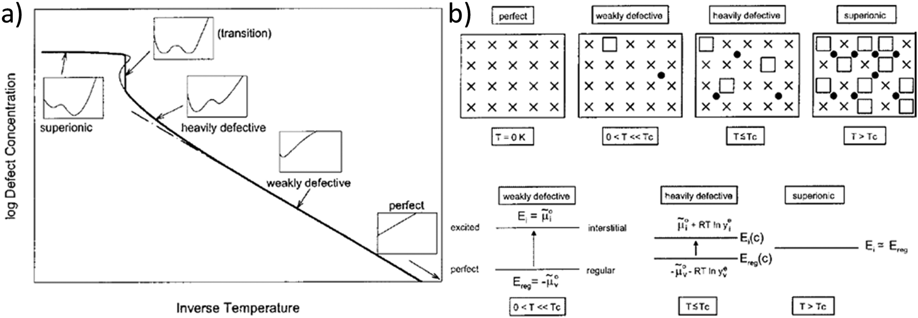 | ||
| Fig. 1 Schematic representation of the superionic transition. (a) Schematic plot of defect concentration as a function of temperature. The insets for different regimes (perfect, weakly defective, heavily defective, transition, and superionic) give the respective curves of free enthalpy as function of defect concentration. (b) Crystallographic pictures and energy level diagrams for the different regimes. Reproduced from ref. 18 with permission of John Wiley & Sons. | ||
So far, very little is known about the premelting regime and melting of Li(SCN) at 274 °C without preceding phase transition. In contrast, K(SCN) has been extensively investigated by Schranz11 and Plester et al.,10 and compared to related systems by Fuith.12 K(SCN) undergoes a first order structural phase transition at 142 °C, which is characterized by an upward bending in the volume right before the transition.11 For the nonlinear volume and conductivity changes in the premelting regime of K(SCN) (m.p. 175 °C) Plester et al. concluded that the mere volume thermal expansion is insufficient to explain the increased defect formation, and suggested an additional mechanism of defect stabilization by Coulomb interactions.10
Since thiocyanates exhibit significant thermal volume expansion due to the anisotropic motion of the (SCN)− anion,10,19 in this work the cube-root law approach is employed to describe transport in the premelting regime of Li(SCN) integrating volume changes into the model. The ionic conductivity of Li(SCN) is measured by electrochemical impedance spectroscopy (EIS) close to and beyond its melting point. The data are fitted with the cube-root law approach in two ways: first in the conventional manner with a constant Coulomb interaction parameter J, and second by including the large volume expansion of Li(SCN) at high temperatures, resulting in a temperature dependence of J. The present application of the cube-root law to a Schottky defective material is compared to the Frenkel defective silver halides, and a general comparison of superionic transition temperatures of various material systems is made. The thermodynamic and kinetic data of Li(SCN) are compiled and compared to other materials to complete this extensive trilogy study (Parts I1 to III) on anhydrous Li(SCN).
Results and discussion
The previously reported ion transport results of doped and undoped Li(SCN) in Part I1 and II2 were collected under conditions of low defect concentrations, i.e. a dilute defective system, where Coulomb defect–defect interactions between the native carriers can be neglected. However, near the melting point the material transforms into a concentrated defective system. In case of Frenkel defects, the cation sublattice becomes completely disordered (also referred to as “molten sublattice”) and the material becomes superionic.4,20 In the case of Schottky defects (in contrast to Frenkel disorder) both cation and anion sublattices are affected. This means that the defect concentrations can only increase until the defect lattice shows the same occupancy as the regular lattice (1/2 of all available lattice sites) before the material melts.Li(SCN) exhibits a pronounced lattice expansion, which is a general feature for thiocyanates due to the local motion of the (SCN)− anions.10,19Fig. 2 shows that for Li(SCN) the expansion is anisotropic (as observed for other thiocyanates),11,19 being strongest in the b direction. The volumetric expansion approaches 5% close to the melting point. This expansion is moderately larger than for LiI (4% from 25 °C to 270 °C).21 Nevertheless, it approximately follows a linear relation without anomaly up to the melting point.
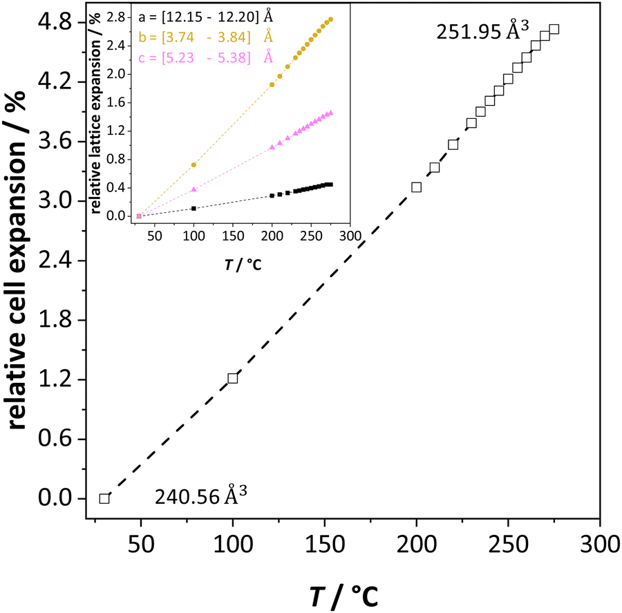 | ||
| Fig. 2 Unit cell volume expansion of undoped Li(SCN) as a function of temperature. The insert shows the lattice expansion in directions a (black), b (orange) and c (magenta), respectively. | ||
In the following we will consider the impact of the relative cell volume expansion on the superionic phase transition in Li(SCN), and for this purpose ignore the anisotropy of the lattice expansion. The volume expansion of Li(SCN) can be extracted from the data in Fig. 2:
| ΔV(T) = 4.60 × 10⁻²⁶ cm3 K−1·T − 2.27 × 10⁻²² cm3 | (1) |
 and thiocyanate
  vacancies are substantial in this premelting regime, the employed model considers only the contribution of
  to the ionic conductivity. The mobility of
  is too low to be significant. It would require a jump of the comparably large (SCN)− anion, which is considered relevant only in the molten state. Since the phase transition is of first order, the transition occurs discontinuously, and a fit can only be conducted in the premelting regime (up to ≈270 °C, cf. Experimental for more information). In a first approach, the possible impact of the volume expansion was not included in the fitting, and the Coulomb interaction parameter J was taken to be temperature independent (Fig. 3, dark blue lines). With this approach the data in the premelting regime of solid Li(SCN) (Fig. 3a, full squares) could be fitted up to 261 °C (Fig. 3a, dark blue solid line). The resulting fitting parameters were used to simulate data beyond 261 °C (Fig. 3a, dark blue dashed line). However, in view of the remarkable volume effects, this approach was not able to successfully describe the complete premelting regime in Li(SCN).
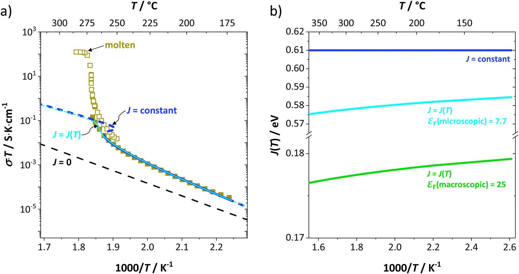 | ||
| Fig. 3 (a) Measured conductivities of undoped Li(SCN) in the premelting regime (full squares, only every 4th data point is shown) and upon melting (open squares, only every 50th data point is shown). All lines correspond to non-linear fits of the premelting regime with J = 0 (black dashed line), J = constant (dark blue solid and dashed line), and J = J(T) (light blue solid and dashed line). For J = constant the volume change was neglected, while for J = J(T) the volume change was included using the Madelung approach with the microscopic dielectric constant εr(microscopic). (b) Coulomb interaction parameter J shown for three different cases: (i) temperature independent J = constant (dark blue solid line); temperature dependent J = J(T) (green solid line), calculated with the Madelung approach using the macroscopic dielectric constant εr(macroscopic), (ii) temperature dependent J = J(T) (bright blue solid line) calculated with the Madelung approach using the microscopic dielectric constant εr(microscopic). | ||
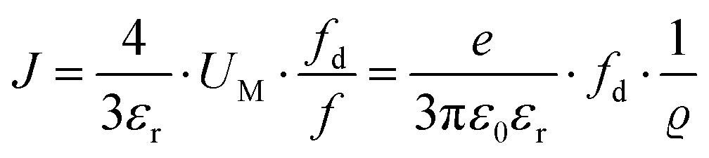
In the second approach the volume expansion was included into the calculations, which makes the Coulomb interaction parameter temperature dependent, and J = J(T). J(T) describes Coulomb interactions and is related to the Madelung energy of the defect lattice. The Madelung energy is proportional to the reciprocal lattice constant, thus the inclusion of eqn (1) into the original cube-root model introduces a temperature dependence of J (i.e. J(T) ∝ 1/lattice constant(T)). However, the calculated values for J(T) from eqn (12) in the Experimental section are far too low to describe the Coulomb interaction in Li(SCN) (Fig. 3b, green solid line) when the high macroscopic dielectric constant of 25 for Li(SCN) is used (which reflects the strong polarizability of the (SCN)− anion). Since the cube-root law approach is essentially an effective Madelung model with the “mean-field approach”, the overestimation of the (SCN)− anion polarizability has to be corrected by employing a smaller, microscopic dielectric constant in the calculations (comparable to a system with a less polarizable anion, e.g. like LiF with εr ≈ 9).24 In contrast to the macroscopic dielectric constant, the microscopic one describes the interaction of charged defects ( to
to  ) at atomistic distances. The macroscopic dielectric behavior may contain significant contributions from longer-range collective relaxations in a certain volume element (e.g. the octahedra in BaTiO3). If the distance between interacting defects is reduced below such length scales (i.e. shrinks to atomistic distances), the dielectric constant is lowered to a “microscopic” value. Such a rationale was also invoked e.g. for PbF2 and SrTiO3.23,25 A decrease of permittivity as a consequence of effects such as local distortions, proximity to charged defects, or decreasing grain size is well known and was investigated in detail e.g. for SrTiO3.26,27 Therefore, εr(microscopic) was used as a parameter in the refinement with reasonable boundaries and J(T) directly calculated to fit the data (Fig. 3a and b, light blue solid lines). With this approach considering the impact of the volume expansion the entire premelting regime up to 270 °C could be fitted.
From the data in Fig. 3a (full and open squares) it is obvious that melting of Li(SCN) occurs as a first order transition, as expected. This is also reflected by the simulated data above 261 °C in Fig. 3a (dark blue dashed line) using J = constant, which yields a similar swerve as obtained for AgCl and AgBr in Fig. 4. Interestingly, including the volume expansion changes the behavior of the simulated data, and it resembles rather a second order or diffuse phase transition (cf. PbF2 in Fig. 4). This means that if Li(SCN) did not melt before, the occurring transition would be of second order when volume changes are considered. Overall, the superionic transition of Li(SCN) in the premelting regime is well described with the cube-root law (Fig. 3a).
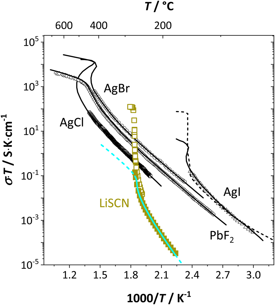 | ||
| Fig. 4 Comparison of first and second order superionic phase transitions in different materials; brown squares and bright blue line for Li(SCN) (this study, cf. also Fig. 3a), black symbols and solid lines for PbF2, AgCl, AgBr, AgI,4 and dashed line for AgI.20 | ||
The Coulomb interaction parameter J between the intrinsic  defects in Li(SCN) has a value of ∼0.6 eV in the premelting regime. This is slightly higher than for β-AgI and lower than for AgBr.4 In the row of the silver halides (all with Frenkel disorder), J scales inversely with the size of the anion and becomes smaller when the lattice parameter is increased. Since Li+ is smaller than Ag+ but (SCN)− is larger than I−, the resulting defect interactions seem to be comparable. The superionic transitions of Li(SCN) and β-AgI in Fig. 4 are rather similar in appearance. However, Li(SCN) is Schottky disordered, which means that in order to become superionic, both cation and anion sublattices must have a defect concentration similar to the number of lattice sites, and at least one must have a high mobility. As discussed in Part II,2 the mobilities of cation and anion can be (and indeed often are) correlated, and in case of a Schottky disordered material it is therefore more likely that the completely molten state is more stable. In contrast, in Frenkel disordered β-AgI a stable situation can be reached in which only the cation lattice is molten (transition to α-phase).
The cube-root law application in Fig. 3a and 4 nicely describes the conductivity data right up to the transition point, after which a “jump” occurs. Here, the model cannot predict the behavior anymore, as mobility effects are not included. In contrast to the silver halides, for Li(SCN) the increase in volume had to be incorporated in the model. Large volume increases are often seen for systems with complex anions,12,28,29 and have also been observed in other thiocyanates.11,19
One can find examples of superionic phase transitions for various ion conductors in literature, as shown in Fig. 5. This is not surprising, as every ionic crystal will enter some sort of regime where its defect concentration increases excessively, unless a first order transition occurs “earlier” (i.e. at lower temperature). A general trend for the temperature range of the superionic transition is difficult to discern. Overall, “soft” ionic systems with large polarizable ions such as Ag+, or with flexible hydrogen bonds in proton conductors tend to have lower transition temperatures.
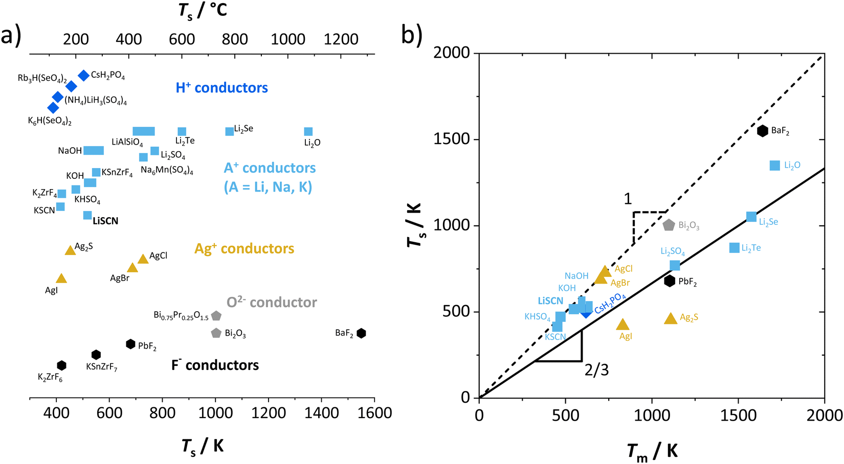 | ||
| Fig. 5 Comparison of superionic phase transition temperatures for different materials with mobile ions such as F−,5,9 O2−,6,30 Ag+,5,31 Li+,7,15,32 Na+,8,33 K+,8,9,11,16 and H+.14,34–36 (a) Superionic transition temperatures Ts for various ionic conductors; (b) correlation of Ts for selected ion conductors from (a) with the respective melting temperatures Tm. The values of Ts and Tm were either directly taken from literature, or as phenomenological onset temperatures from respective data (intersection point from linear fits before and after transition (cf.Fig. 7), estimated error of ∼10 K). | ||
Regarding the onset temperature of the superionic transition and the melting point (Fig. 5b, also cf. Fig. 3 in ref. 5), one can generally expect that for a Schottky defective material both temperatures are rather close. This is indicated in Fig. 5b by the dashed line with a slope of 1. As mentioned above, the necessary condition for a superionic transition is difficult to achieve for Schottky defects without the melt taking over as most stable state. Instead, in (anti-)Frenkel defective materials high defect concentrations do not necessarily mean a collapse of the lattice, and a superionic transition can occur before the melting point (note that melting of a Frenkel disordered material occurs if both sublattices being molten is the more stable state than only one sublattice). The onset of the superionic transition often occurs at approximately 2/3 of the melting point (Fig. 5b, solid line with slope of 2/3). This is reminiscent of the Tammann rule (well known in solid state chemistry) stating that a material becomes reactive at roughly 2/3 of its melting temperature. Within the cube-root model, this can be rationalized from the fact that in this temperature range the defect formation approaches the superionic transition.5 The Tammann rule should in particular apply for Schottky disordered materials, since there both sublattices are involved in defect formation. The investigation of the defect chemistry in the premelting regime, i.e. superionic transition, might therefore also be indicative of the intrinsically formed defect types, which can help to identify the mobile defect if other methods such as doping are difficult to perform.
Finally, we can compare the thermodynamic and kinetic data of Li(SCN) from the experimental study in Part I1 to the obtained values from the cube-root law fitting, and to literature data (Table 1). The Li(SCN) data sets agree reasonably well with each other within the experimental uncertainties. The largest deviations are observed for the entropy terms, which reflects the error-proneness of this quantity. The comparison of the defect formation enthalpy ΔH° and Coulomb defect–defect interaction parameter J reflects the types of defects, and, more importantly, the overall chemistry of the materials, which also involves the other sublattice. The most important factor is the ion charge, which explains the difference between the oxygen vacancy conductor Bi0.75Pr0.25O1.5 and the other materials. The respective sublattice composition is determining for defect–defect interactions, evident by comparing the silver halides for which J decreases with increasing anion size. However, these considerations only apply to the defect formation thermodynamics. Regarding Li(SCN), the values of ΔH° and J suggest a similar defect chemistry to the silver halides (despite being Schottky and not Frenkel disordered). However, the enthalpy of migration for long-range ion transport in Li(SCN) is much higher compared to the silver halides, and almost the same as for  migration. This strong mobility suppression was addressed in Part II,2 and reflects the occurrence of slow reorientational processes of (SCN)− during cation jumps. This is the origin of the very different transport properties of Li(SCN). Table 1 nicely shows that the cube-root law approach can be applied to (anti-)Frenkel as well as Schottky defective materials, yet some additional, material specific considerations might have to be included (e.g. anisotropic ion transport in Bi0.75Pr0.25O1.5 or lattice expansion in Li(SCN)). Li(SCN) demonstrates how important specific effects can be for ion transport, i.e. the very different Li–N and Li–S interaction strengths of an anisotropic (SCN)− anion.
| Compound | Type of defects | ΔH°/eV | ΔS°/kB | ΔmHj/eV | log10[νj/(cm2 K s−1 V−1)] | J/eV | γ = J/ΔH° | γ crit | Ref. | |
|---|---|---|---|---|---|---|---|---|---|---|
| PbF2 | anti-Frenkel | Cube-root | 1.08 | 8.48 | 0.18 | 2.94 | 0.75 | 0.69 | 0.78 | 4 |
| AgCl | Frenkel | Cube-root | 1.48 | 9.73 | 0.05 | 2.48 | 1.03 | 0.70 | 0.58 | 4 |
| AgBr | Frenkel | Cube-root | 1.15 | 7.67 | 0.15 | 3.22 | 0.80 | 0.70 | 0.65 | 4 |
| β-AgI | Frenkel | Cube-root | 0.82 | 11.77 | 0.24 | 1.60 | 0.50 | 0.61 | 0.58 | 4 |
| Bi0.75Pr0.25O1.5 | anti-Frenkel | Cube-root | 1.51 | 5.78 | 0.90 | 2.01 | 1.78 | 1.18 | 1.34 | 6 |
| 0.48 | ||||||||||
| Li(SCN) | Schottky | Long-range hopping | 0.6 ± 0.3 | 5 ± 2 | 0.89 ± 0.08 | 5.1 ± 0.4 | 1 | |||
| Local hopping | 0.6 ± 0.1 | 2 ± 1 | 2 | |||||||
| Cube-root J | 0.6 | 3.0 | 0.8 | 3.5 | 0.61 | 1.02 | 0.96 | This work | ||
| Cube-root J(T) | 0.8 | 7.9 | 0.7 | 2.4 | 0.57–0.59 | 0.72–0.73 | 0.70 | This work |
Conclusion
The cube-root law for quantifying Coulomb defect–defect interactions in a concentrated system was successfully applied to the superionic transition in the premelting regime of anhydrous Li(SCN) to describe the non-linear conductivity increase. Two fitting models were employed; in one the Coulomb interaction parameter J is constant, while in the other it is temperature dependent to account for the substantial lattice volume expansion in Li(SCN). The inclusion of volume expansion enabled a smoother and more stable data fit without increasing the number of fitting parameters. The inclusion of volume changes, however, was not able to account for the complete conductivity increase upon melting, as additional mobility effects are not included. Together with literature examples, these investigations show that the cube-root law approach is very useful to better understand the behavior of mobile defects, phase transitions, and even general material properties such as reactivity at elevated temperatures and impact of lattice expansion.Experimental
General
Synthesis, sample preparation, measurement conditions and set-ups were reported in Part I1 of this series on anhydrous Li(SCN). Temperature dependent X-ray diffraction measurements on Li(SCN) were performed according to the procedure described in the Supporting Information of Part I.1 Regarding electrochemical impedance spectroscopy, some additional remarks have to be made. At temperatures close to the melting point (premelting regime) of Li(SCN), the EIS measurement conditions were changed compared to the ones reported in Part I. Measurements were taken continuously with 1 K steps without equilibration for 24–30 times. Measurements above the m.p. could not be conducted under high vacuum, since the material would start to sublimate. Therefore, both the drying as well as EIS measurements were conducted under constant flow of dry Ar or N2 gas (typically 50–100 sccm). Due to the phase transition (melting point), a different measurement cell geometry was used for these measurements. Li(SCN) powder was filled into a fused silica crucible equipped with Pt electrodes to measure the impedance directly from the molten or resolidified sample. The cell constant was determined with aqueous KCl solutions. For these measurements at high temperatures, the stray impedance of the set-up (measured separately by short-circuiting the electrodes) interfered, and therefore had to be pointwise subtracted. Exemplary impedance spectra before and after melting are shown in Fig. 6.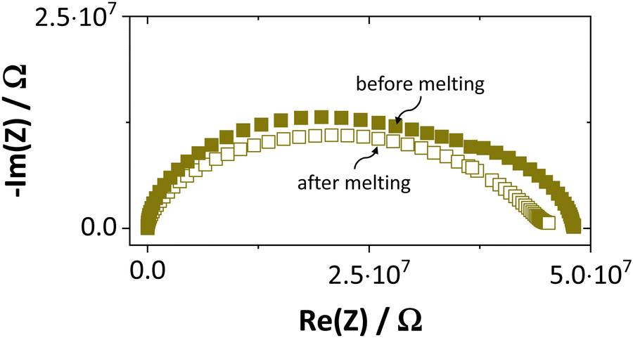 | ||
| Fig. 6 Exemplary impedance spectra of anhydrous Li(SCN) at 134 °C before and after melting. | ||
The onset temperature of a superionic transition was determined by linearly fitting the conductivity data in the Arrhenius plot before and after the transition, as shown in Fig. 7. Since the fitting range is set by visual inspection, values obtained with this method can vary to some degree (estimated error up to ∼10 K). However, this uncertainty is negligible relative to the temperature range considered for the materials comparison in Fig. 5.
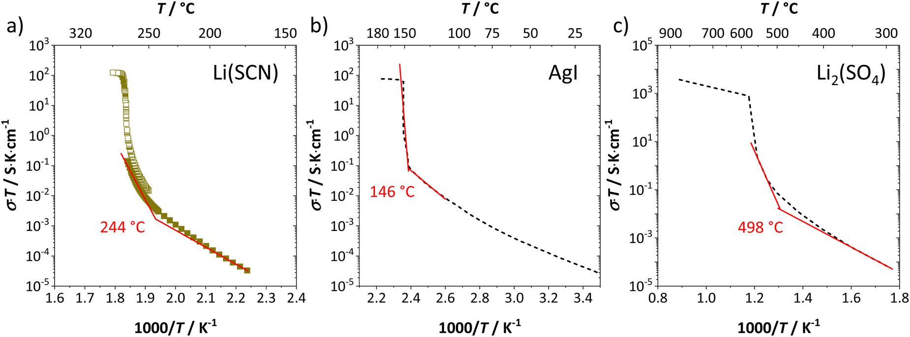 | ||
| Fig. 7 Exemplary procedure to determine the superionic transition of (a) Li(SCN), (b) AgI,4,20 and (c) Li2(SO4).7,37 Symbols and black dashed lines are measured data, and red solid lines are linear fits before and after the transition. The shown temperatures are the obtained onset temperatures of the superionic transition. | ||
Cube-root law model fitting
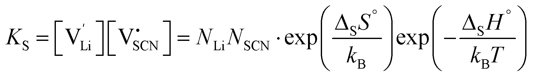
Conductivity data of Li(SCN) between 174 and 270 °C (premelting regime: 242–270 °C) were fitted with the cube-root law described in literature.4–6,17,18,23 The fitting was conducted with Matlab (Mathworks, Version R2017a) using the lsqnonlin-function. A function handle was created in which the implicit equation for defect concentration was solved iteratively with the vpasolve-function at every temperature step. All parameters had to have reasonable boundaries for the fit to converge. The fits had a low residual sum of squares in the range of ∼0.1 or smaller. The impact of lattice expansion in the premelting regime for defect–defect interactions was considered and compared to fitting with constant J, as discussed in the main text.Li(SCN) is a Schottky defective material. Accordingly, in the intrinsic regime we have:
 | (2) |
 | (3) |
 and
and  the respective vacancy concentrations, NLi = NSCN are the number of available sites in the lattice, ΔSS° and ΔSH° the standard Schottky entropy and enthalpy of formation, kB the Boltzmann constant, and T the temperature.
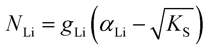
One can redefine NLi into NLi = gLi·αLi, in which gLi is the degeneracy of Li sites and αLi the number of occupiable Li sites. If one defines gLi and αLi per unit cell (Z = 4),38NLi = 1·4, and if one defines it per lattice site, NLi = 1·1. In the linear regime (T ≤ 242 °C) the system is considered dilute and Maxwell–Boltzmann statistics apply. However, in the (non-linear) premelting regime with 242 °C ≤ T ≤ 270 °C the system becomes concentrated and Fermi–Dirac statistics have to be used (within the Brouwer approximation,  ):4,18
 | (4) |
 can be regarded as the equilibrium defect concentration,
  .
.
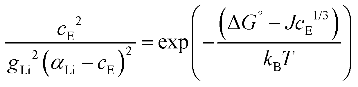
In a concentrated (superionic) defective state Coulomb interactions between oppositely charged defects become significant. Therefore, a Coulomb interaction term μint(cE) (μint(cE) < 0, since the Coulomb interaction is stabilizing) is introduced; ΔSG° = ΔG° + μint(cE). It was suggested that this Coulomb interaction follows a cube-root law dependence yielding:4
| μint(cE) = −JcE1/3 | (5) |
The final equation, which was used to iteratively calculate the defect concentrations of Li(SCN) at respective temperatures in Matlab with vpasolve (cE as symbolic variable) can be expressed as:
 | (6) |
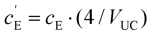 , where VUC is the unit cell volume of Li(SCN) (VUC = 240.56 × 10⁻²⁴ cm3).38
The mobilities were calculated according to:
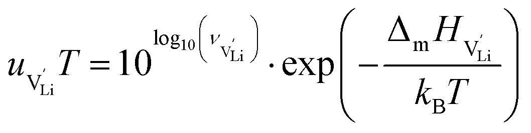 | (7) |
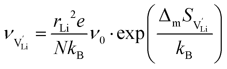 | (8) |
 is the mobility,
  the pre-exponential factor,
  and
and  are the enthalpy and entropy of migration,
  and N are the distance to and the number of available neighboring sites, e is the charge of an electron and ν0 is the jump attempt frequency of lithium vacancies.39 The correction term for mobility in concentrated systems proposed in ref. 4 did not lead to improvements in the fitting and was therefore neglected. Eqn (6) and (7) were combined to calculate the conductivity
  according to:
 | (9) |
 is the valence of
  (equal to 1 for Li+).
With the above set of equations, the cube-root model can be used to fit conductivity data as a function of 1000/T using a total of 5 parameters: ΔSS°, ΔSH°, J,  and
and  . The described approach (J is a constant parameter) was capable of fitting conductivity data up to 261 °C.
However, at higher temperatures the model failed to describe the data. A possible reason for this failure was the neglect of volume expansion in Li(SCN) in the premelting regime. The volume expansion ΔV(T) was derived from in situ XRPD data yielding:
| ΔV(T) = 4.60 × 10⁻²⁶ cm3 K−1·T − 2.27 × 10⁻²² cm3 | (10) |
 | (11) |
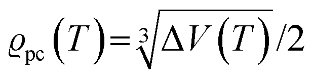 . The impedance measured dielectric constant (∼25 in the premelting regime) is a macroscopic magnitude (εr(macroscopic) = εmar), however, for defect–defect interactions the microscopic dielectric constant (εr(microscopic) = εmir) has to be considered.23,25 Finally, we derive the following equation:
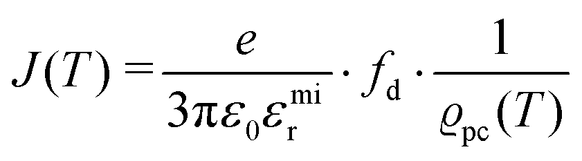 | (12) |
Author contributions
All authors have contributed to the experimental results, calculations and writing of the manuscript, and have given their approval to the final version of the manuscript.Conflicts of interest
There are no conflicts to declare.Acknowledgements
We want to thank Annette Fuchs for her help in determining the impedance measurement cell constant, and Robert Usiskin for his very useful contributions in writing the Matlab script. We also want to thank Max Hödl for proof reading the manuscript. Open Access funding provided by the Max Planck Society.References
- M. Joos, M. Conrad, A. Rad, P. Kaghazchi, S. Bette, R. Merkle, R. E. Dinnebier, Th. Schleid and J. Maier, Phys. Chem. Chem. Phys., 2022 10.1039/D2CP01836E.
- M. Joos, M. Conrad, I. Moudrakovski, M. W. Terban, A. Rad, P. Kaghazchi, R. Merkle, R. E. Dinnebier, Th. Schleid and J. Maier, Phys. Chem. Chem. Phys., 2022 10.1039/D2CP01837C.
- H. Schmalzried, Z. Phys. Chem., 1959, 22, 199–208 CrossRef CAS.
- N. Hainovsky and J. Maier, Phys. Rev. B: Condens. Matter Mater. Phys., 1995, 51, 15789–15797 CrossRef CAS PubMed.
- R. Merkle and J. Maier, Z. Anorg. Allg. Chem., 2005, 631, 1163–1166 CrossRef CAS.
- J. Jamroz, M. Malys, F. Krok, J. Maier, A. Kyriacou, S. J. Ahmed, I. Abrahams and W. Wrobel, Solid State Ionics, 2020, 348, 115284 CrossRef CAS.
- C. N. Wijayasekera and B. E. Mellander, Solid State Ionics, 1991, 45, 293–298 CrossRef CAS.
- Y. M. Baikov and V. M. Egorov, Phys. Solid State, 2009, 51, 33–43 CrossRef CAS.
- V. Kavun, N. Uvarov, A. Slobodyuk, V. Goncharuk, A. Kotenkov, I. Tkachenko, A. Gerasimenko and V. Sergienko, Russ. J. Electrochem., 2005, 41, 501–509 CrossRef CAS.
- D. W. Plester, S. E. Rogers and A. R. Ubbelohde, Proc. R. Soc. London. Ser. A: Math. Phys. Sci., 1956, 235, 469–481 CrossRef CAS.
- W. Schranz, Phase Transitions, Gordon and Breach Science Publishers, S.A., 1994, vol. 51, pp. 1–66 Search PubMed.
- A. Fuith, Phase Transitions, 1997, 62, 1–93 CrossRef CAS.
- M. Witschas, H. Eckert, D. Wilmer, R. D. Banhatti, K. Funke, J. Fitter, R. E. Lechner, G. Korus and M. Jansen, Z. Phys. Chem., 2000, 214, 643 CAS.
- A. R. Lim, Solid State Commun., 2013, 160, 22–25 CrossRef CAS.
- J. Schneider, T. Schröder, M. Hoelzel, O. Kluge, W. W. Schmahl and O. Oeckler, Solid State Ionics, 2018, 325, 90–101 CrossRef CAS.
- D. Swain, V. S. Bhadram, G. K. Pradhan, S. V. Bhat, C. Narayana and C. N. R. Rao, J. Phys. Chem. A, 2010, 114, 10040–10044 CrossRef CAS PubMed.
- J. Maier, Physical Chemistry of Ionic Materials, John Wiley & Sons, Ltd, 2004 Search PubMed.
- J. Maier and W. Münch, Z. Anorg. Allg. Chem., 2000, 626, 264–269 CrossRef CAS.
- M. Joos, M. Conrad, R. Merkle, Th. Schleid, J. Maier, R. E. Dinnebier and S. Bette, Dalton Trans., 2021, 50, 6949–6991 RSC.
- J. S. Lee, S. Adams and J. Maier, J. Phys. Chem. Solids, 2000, 61, 1607–1622 CrossRef CAS.
- M. P. Tosi, Solid State Phys., 1964, 16, 1–120 CAS.
- C. B. Baddiel and G. J. Janz, Trans. Faraday Soc., 1964, 60, 2009–2012 RSC.
- F. Zimmer, P. Ballone, M. Parrinello and J. Maier, Solid State Ionics, 2000, 127, 277–284 CrossRef CAS.
- K. F. Young and H. P. R. Frederikse, J. Phys. Chem. Ref. Data, 1973, 2, 313–410 CrossRef.
- R. Merkle and J. Maier, Phys. Chem. Chem. Phys., 2003, 5, 2297–2303 RSC.
- R. Waser, Integr. Ferroelectr., 1997, 15, 39–51 CrossRef CAS.
- J. Petzelt, Ferroelectrics, 2010, 400, 117–134 CrossRef CAS.
- H. von Benda and K. von Benda, Z. Naturforsch., 1979, 34b, 957–968 CrossRef CAS.
- E. A. Secco, J. Solid State Chem., 1992, 96, 366–375 CrossRef CAS.
- N. M. Sammes, G. A. Tompsett, H. Näfe and F. Aldinger, J. Eur. Ceram. Soc., 1999, 19, 1801–1826 CrossRef CAS.
- O. Alekperov, N. Gasimov, K. Khalilova, Y. Shim, R. Paucar, N. Abdulzade, O. Samedov, Z. Jahangirli, E. Nakhmedov, K. Wakita and N. Mamedov, Phys. Status Solidi Curr. Top. Solid State Phys., 2015, 12, 605–609 CAS.
- B. Singh, M. K. Gupta, R. Mittal and S. L. Chaplot, J. Mater. Chem. A, 2018, 6, 5052–5064 RSC.
- V. Sharma, D. Swain and T. N. Guru Row, Inorg. Chem., 2017, 56, 6048–6051 CrossRef CAS PubMed.
- O. S. Hernández-Daguer, H. Correa and R. A. Vargas, Ionics, 2015, 21, 2201–2209 CrossRef.
- A. Pawłowski, L. Szcześniak, M. Połomska, B. Hilczer and L. Kirpichnikova, Solid State Ionics, 2003, 157, 203–208 CrossRef.
- J. Otomo, T. Tamaki, S. Nishida, S. Wang, M. Ogura, T. Kobayashi, C. J. Wen, H. Nagamoto and H. Takahashi, J. Appl. Electrochem., 2005, 35, 865–870 CrossRef CAS.
- S. Pizzini, J. Appl. Electrochem., 1971, 1, 153–161 CrossRef CAS.
- O. Reckeweg, A. Schulz, B. Blaschkowski, Th. Schleid and F. J. DiSalvo, Z. Naturforsch., 2014, 69b, 17–24 CrossRef.
- S. Lorger, R. E. Usiskin and J. Maier, Adv. Funct. Mater., 2019, 29, 1–11 CrossRef.
Footnote |
| † Present address: Institut für Photovoltaik, University of Stuttgart, Pfaffenwaldring 47, 70569 Stuttgart, Germany. |
| This journal is © the Owner Societies 2022 |