
 Open Access Article
 This Open Access Article is licensed under a
 Creative Commons Attribution 3.0 Unported Licence
Effect of unwanted guest molecules on the stacking configuration of covalent organic frameworks: a periodic energy decomposition analysis†
A. D. Dinga
Wonanke
 * and
Matthew A.
Addicoat
*
* and
Matthew A.
Addicoat
*
School of Science and Technology, Nottingham Trent University, Nottingham, NG11 8NS, UK. E-mail: dinga.wonanke@kit.edu; matthew.addicoat@ntu.ac.uk
First published on 13th June 2022
Abstract
Elucidating the precise stacking configuration of a covalent organic framework, COF, is critical to fully understand their various applications. Unfortunately, most COFs form powder crystals whose atomic characterisations are possible only through powder X-ray diffraction (PXRD) analysis. However, this analysis has to be coupled with computational simulations, wherein computed PXRD patterns for different stacking configurations are compared with experimental patterns to predict the precise stacking configuration. This task is often computationally challenging firstly because, computation of these systems mostly rely on the use of semi-empirical methods that need to be adequately parametrised for the system being studied and secondly because some of these compounds possess guest molecules, which are not often taken into account during computation. COF-1 is an extreme case in which the presence of the guest molecule plays a critical role in predicting the precise stacking configuration. Using this as a case study, we mapped out a full PES for the stacking configuration in the guest free and guest containing system using the GFN-xTB semi-empirical method followed by a periodic energy decomposition analysis using first-principles Density Functional Theory (DFT). Our results showed that the presence of the guest molecule leads to multiple low energy stacking configurations with significantly different lateral offsets. Also, the semi-empirical method does not precisely predict DFT low energy configurations, however, it accurately accounts for dispersion. Finally, our quantum-mechanical analysis demonstrates that electrostatic-dispersion model suggested Hunter and Sanders accurately describes the stacking in 2D COFs as opposed to the newly suggested Pauli-dispersion model.
1 Introduction
Over the years, a considerable amount of effort has been geared towards exploring the potential application of nanoporous materials in gas storage and sieving, filtration, extraction, separation, and catalysis.1–8 The main breakthrough in this research dates from 1994, when Yaghi and co-workers introduced a new synthetic approach, commonly referred to as reticular chemistry, which uses carefully designed building blocks to create extended crystalline structures.9–11 The peculiarity of this approach is the ability to assemble predefined crystalline structures from judiciously designed molecular building blocks whose structural integrity and rigidity are preserved throughout the assembly process. The successful implementation of this synthetic approach has resulted in an ever-increasing scientific and industrial interest in the synthesis and application of a plethora of nanoporous materials, which can be classed as Metal–Organic Frameworks (MOFs),12 Metal–Organic Polyhedra (MOPs),13 Zeolite Imidazolate Frameworks (ZIFs),14 and Covalent Organic Frameworks (COFs).15COFs are an interesting class of nano-porous molecules, wherein organic linker molecules are stitched together by connector molecules, which are also organic, to form a framework that is held together by strong covalent bonds. In comparison to other porous materials, COFs present the advantage that they are made mainly from lightweight elements such as carbon, oxygen, hydrogen, nitrogen and boron. Consequently, they have relatively low mass densities with a comparably large surface area, tunable pore sizes and structures, easily functionalisable and versatile covalent combination of building units.16,17
Despite the advantages that COFs present over other nano-porous materials, there is a significant challenge in elucidating their packing sequence, which is of paramount importance for their optoelectronic, catalytic and sorption properties. For instance, in two-dimension, the organic linkers are topologically stitched together to form 2D monolayers. These monolayers in turn stack together in a third dimension via non-covalent interactions to form layered structures.18 However, these weak non-covalent interactions between layers often lead to the formation of layered structures with ill-defined polytypes, which are either polycrystalline or amorphous solids. Unfortunately, a detailed atomic characterisation of these solids is not possible since they are insensitive to most analytical techniques such as solid-state nuclear magnetic resonance (NMR) or single X-ray diffraction analysis.19 Hence, the characterisation of COFs predominantly rely on powder X-ray diffraction (PXRD) analysis. Although essential dataset for structural analysis and simulations can be obtained from PXRD analysis, the absence of single crystals renders the identification of a suitable stacking structure elusive.20 Consequently, PXRD analyses are mostly coupled with other analysis to get a glimpse of the geometry and stacking arrangement of any newly synthesised COF. For example, transmission electron microscopy, TEM, analysis is often used to determine the composition of the COF.21 Meanwhile, computational calculations are used to predict their geometric parameters and packing arrangement. This is generally done by computing educated guesses of periodically bound systems and comparing the computationally determined PXRD patterns to those obtained experimentally.
Early attempts in the elucidation of the stacking arrangement of 2D COFs led to the identification of two stacking arrangements, the eclipsed (AA) and the staggered (AB) arrangement. In the eclipsed arrangement, layers lie directly on the top of the other consequently aligning the hexagonal pores of each layer to generate a 1D pore system.22–24 However, the perfectly eclipsed structures are not energetically favourable due to repulsive interactions between like-atoms from adjacent layers. Therefore, off-centred or laterally displaced energy minima, also referred to as slip-stacked structures, are commonly assumed as the eclipsed stacking arrangement.25–27 However, the exact slip-stacked structures for any COFs are elusive since layer offset can occur in any direction, termed turbostratic disorder. Consequently, higher symmetry structures based on eclipsed layer stacking are usually assumed as an average structure model.18 On the other hand, the staggered stacking arrangement involves a layering in which, each layer is offset by half unit cell resulting in three connected vertices laying directly over the centre of the pore of the adjacent layer.22 This stacking arrangement is similar to layering in graphite in which three connected vertices, carbon-atoms, lie directly over the centre of a six-membered ring of the adjacent layer. So far, such stacking arrangements have been observed only in COF-1.15
To this day, the unprecedented staggered stacking arrangement observed in COF-1 is highly contended amongst COF chemists. The crystal structure of COF-1 is known to possess a guest mesitylene at the centre of the pore in each periodically bound layer, which could be the reason for this AB stacking arrangement. This can be justified by the fact that the COF was reported to loss its crystallinity when heated to 200 °C to remove the guest molecule.15 From a series of computational study performed by Heine and co-workers,26 the authors showed that in the absence of the guest molecule, the inclined and serrated eclipsed structures were the energy minima. In 2013, Ravikovitch and coworkers performed an in-depth study on the irreversible phase transition resulting from the removal of the guest mesitylene molecule.22 More recently, Jiang and co-workers investigated the host–guest interaction of the mesitylene guest molecule in the confinement of pore channels in COF-1 as well as the effect of the guest molecule on the variation in PXRD patterns.20
The ambiguity surrounding the stacking pattern of COF-1 depending on the presence (AB preferred) or absence (AA preferred) of the guest molecule – is an extreme case where the effect of an unwanted guest molecule is critical in correctly predicting stacking configurations. For this reason, COF-1 represents an excellent candidate for exploring the effect of unwanted guest molecules (which are present in most experimentally synthesised COFs) in simulated stacking structures. We believe that this can apply to all COFs and should be taken into account when computational simulations have to be used in predicting the stacking configuration of newly synthesised COFs.
2 Computational method
2.1 Modelling the stacking geometries
The variation of the non-covalent intermolecular interactions in the stacking of COF-1 was evaluated by plotting out full potential energy surfaces for both the guest free and guest containing structures of COF-1, which are represented in Fig. 1a and b respectively. The effect of the guest on π-stacking arrangement was further accessed through using both mesitylene and benzene as guest molecules. | ||
| Fig. 1 Structural representation of COF-1, where (a), represents the guest-free structure, while (b) represents the guest-containing structure. | ||
For an optimal computational cost, full potential energy surfaces (PES) to effectively evaluate interlayer heights between monolayers were first computed for both structures in Fig. 1 using the Geometry, Frequency, Non-covalent, eXtended Tight Binding (GFN-xTB) method.28 The GFN-xTB method is a computationally and numerically robust semi-empirical tight-binding method that has been designed for computing highly accurate molecular properties for elements across the entire periodic table, up to Z ≤ 86. While this study examines a well-known COF with only four elements, B, C, O and H; several COFs may be substituted to include one or more metal atoms – e.g. in the centre of a phthalocyanine or porphyrin29 building block,30,31 or COFs may be post-metallated in order to create a platform for catalysis.32 It is desirable in all these cases, to treat the “bare” and metallated COFs with the same computational method, and therefore the wide periodic table coverage of GFN-xTB is a highly useful feature. In comparison to other semi-empirical methods that employ minimal atomic orbital basis sets, which limit the accuracy, GFN-xTB uses an atom centred minimal basis set, which are Slater functions that are augmented with a second s-function and a d-polarisation function to enable a proper description of hydrogen bonding and hyper-valent bonding arrangements respectively. Moreover, it is properly parametrised to inherently account for dispersion correction using the D3 method,33 which is effective in accounting for non-covalent interactions between 2D COF layers.
To generate the PES, bilayers resulting from the optimised monolayers were used. Atoms from one layer of the stacked system were rigidly held in place meanwhile the other layer was translated over the surface of the rigid layer in increments of 0.1 Å along the x and y axes. At every x and y offset, the interlayer distance, z-axis, was scanned from 2.8 Å to 4.00 Å in increments of 0.01 Å and the intermolecular potential energies were computed. A visual illustration of this process can be viewed in the ESI† online at https://zenodo.org/record/6522043/files/Method.mp4?download=1. The configurations with the lowest energy along the z-axis were projected onto the xy plane to enable visualisation of the 3-dimensional data in two dimensions. Also, each of these configurations alongside their optimal interlayer heights was saved for use in computing the periodic energy decomposition analysis (PEDA). The range of layer translation and spacing were probed wide enough to include all minimum energy structures. However, layer rotations were not considered while generating the PES for the simple reason that it could result in a loss in order, which would be computationally intractable to model. Similarly, in order to keep the model tractable, the guest molecule was maintained coplanar with the COF and its orientation within the plane was also fixed as shown in Fig. 1b. The methyl groups of the mesitylene molecule were oriented with one of three hydrogen atoms in the COF plane. The closest interplanar hydrogen–hydrogen distance was noted for the AA stacked structure with a value of 1.857 Å.
A PEDA was then computed for each of the previously computed configurations that constitute the GFN-xTB PES. In setting up this computation, each monolayer was used as a molecular fragment from which their interlayer interactions energies at each configuration were computed using the optimal interlayer heights.34 A summary of this method as applied to this study is found in the ESI† while interested readers are recommended to consult the following references for more details.34–39 The PEDA PES was computed using first-principle density functional theory, DFT. To be precise, we used Grimme3 dispersion corrected33 generalised gradient corrected Perdew, Kieron and Burke exchange–correlation functional PBE-D3,40 alongside the doubly polarised triple-zeta, TZ2P, basis set.41 The PBE-D3/TZ2P, functional has been shown to provide an accurate representation of intermolecular interactions as well as lattice parameters, unit cells and bonding patterns of COFs,34,42,43 thus making it an ideal functional for this study. All computations were performed using the Amsterdam Modelling Suite (AMS) package version ADF2019.305.44
3 Results and discussion
3.1 GFN-xTB generated potential energy surfaces
The PES computed using the GFN-xTB method for the guest free, mesitylene and benzene guest containing structures of COF-1 are presented in Fig. 2a, b and c respectively. The vertical and horizontal axes correspond to the lateral translation along the x and y direction, which range from 0.0–8.0 Å, ensuring that all metastable positions are sampled. The colour gradient corresponds to the energy (eV) of the structure with the most stable interlayer spacing for each lateral translation. | ||
| Fig. 2 Potential energy surface generated from the GFN-xTB method for (a) the guest free structure, (b) the mesitylene guest containing structure, and (c) the benzene guest containing structure (c), of COF-1. Each PES can be divided into five regions with distinct energetic properties represented by the colour gradients that range from black to yellow corresponding to 0–1 eV. | ||
It can be observed from Fig. 2 that the preferred lateral offsets that lead to the lowest potential energy for both the guest free and the guest containing structures do not converge on the same region on the PES. In the PES for the guest free structure, Fig. 2a, the most energetically stable configuration corresponds to a slip-stacked configuration with lateral offsets that span a region of 1.4–2.0 Å represented by the dark arc in Fig. 2a. This displacement coordinate agrees with the lateral offset of 1.4 Å previously reported by Heine and co-workers.26 The corresponding interlayer distances that minimises the interaction energy ranges between 3.1–3.2 Å. The perfectly eclipsed configuration, wherein the lateral offset corresponds to the coordinate (0, 0), is observed to be destabilised by approximately 0.35 eV. Meanwhile, the staggered configurations are observed to be destabilised from the minima by approximately 0.20 eV.
On the other hand, the PES of the guest containing systems of COF-1 are highly corrugated with multiple energy minima at different translational offsets. In the mesitylene guest containing system, these minima are grouped in regions A and B as shown in Fig. 2b. While in the benzene guest containing system, these energy minima are grouped in regions A, B, C and D as shown in Fig. 2c. These numerous stacking configurations could potentially impede experimental reproducibility as a result of synthesised molecules self-assembling into any of these low energy configurations. For instance, only the stack layers in region A of Fig. 2b has PXRD patterns that match those from Yaghi's original synthesis.15 Moreover, numerous synthesis have been reported for the synthesis of COF-1 in literature, wherein authors reported lattice parameters that matched those of the originally synthesised COF to within 80–90% accuracy.45–47 Notwithstanding, most of the PXRD patterns from these syntheses do not fully match that of the originally synthesised COF, consequently suggesting that these newly synthesised COFs might have adopted one of the low energy stacking configurations.
3.2 Periodic energy decomposition analysis
A periodic energy decomposition analysis was performed to fully understand the interactions occurring between the COF layers. In the PEDA scheme, the total interaction energy is decomposed into electrostatic, Pauli repulsion, orbital interaction and dispersion term as fully described in the ESI.† The PES for the total interaction energies between COF layers for both guest free and guest containing systems are presented in Fig. 3. For both COF systems the total interaction energy is observed to differ slightly from the semi-empirical GFN-xTB counterparts. | ||
| Fig. 3 PES of the total interaction energies for (a), the guest free system, (b) the mesitylene guest containing system, (c) and the benzene guest containing system of COF-1 computed at PBE-D3/TZ2P level of theory. An animation illustrating 3D structures that correspond to sample points on the PES can be viewed in the ESI† online at https://zenodo.org/record/6522043/files/Internal_energy_contribution.mp4?download=1. | ||
In the guest free system, Fig. 3a, and the mesitylene guest containing system, Fig. 3b, the minima are observed to be significantly moved from the fully eclipsed structure, meanwhile in the benzene guest containing system, Fig. 3c, the minima span through a continuous symmetric surface on the PES. This indicates a favourable stabilisation effect between the guest molecule and the adjacent COF layer. The displacement coordinates for the 100 stacking configurations, which are within 0.1 eV are presented in the ESI.† Videos that illustrate the structures at different offsets on the PES can be viewed in the ESI† online at ref. 48.
Overall, the presence of the guest molecule provide a plethora of stacking configurations with significantly varied orientations, which are all within 0.2 eV. This implies that these stacking patterns that range from the AB stacking to the various slip-stacked patterns are all likely patterns that can be adopted from actual experiment. Although, this system represents an extreme case wherein the effect of the guest molecule is critical, it indicates that the effect of solvent molecules and other potential guest molecules present in COF crystals should be given more consideration especially when predicting their stacking patterns. Also, the difference in the sampled energy minima configurations between the total interaction energy computed using the first-principles DFT method and the semi-empirical GFN-xTB (and the commonly used DFTB method reported by Heine and co-workers26) further highlights the need for more robust computational methods for simulating COF structures. The performance of the semi-empirical method alongside the effect of the guest molecule can further be investigated by exploring the various contributions to the total interaction energy.
3.3 Electrostatic energy contribution
The electrostatic energy is defined as the interaction between static charge densities in the COF layers. In general, it includes attractive Coulomb interactions between the nuclei of one layer and the electrons in the adjacent layer as well as the nucleus–nucleus and electron–electron repulsive Coulomb interactions between adjacent layers. The PES for the electrostatic energy contribution to the interaction energy is presented in Fig. 4. | ||
| Fig. 4 PES for the electrostatic energy contribution to the interaction energy for (a) the guest free system, (b) the mesitylene guest containing system, (c) and the benzene guest containing system of COF-1 computed at PBE-D3/TZ2P level of theory. An animation illustrating 3D structures that correspond to sample points on the PES can be viewed in the ESI† online at https://zenodo.org/record/6522043/files/Elec_energy_contribution.mp4?download=1. | ||
In stacked COF layers, the electrostatic energy is highly destabilised in the perfectly eclipsed configuration as observed in Fig. 4. This is because nuclei–nuclei and electron–electron repulsion are maximum in this configuration since like atoms from adjacent layers lie directly adjacent to each other. For this reason, the perfectly eclipsed configuration is seldom observed in stacked structures with the same repeating layers. For all COF systems, the electrostatic interaction energy has a stabilising effect on the AB and slip-stacked structures. In the guest-free system, the global minima correspond to systems in which each boraxine ring of the top layer lie at the centre of the pore of the adjacent layer, consequently preventing the electropositive boron–boron and electronegative oxygen–oxygen interactions of adjacent layers, which are highly repulsive. Meanwhile in the guest containing system, the global minima correspond to structures in which layers are stacked such that a boron atom in the 6-membered boraxine ring on one layer lay at the centre of a 6-membered (phenyl/mesitylene) ring of the adjacent layer, similar to the stacking arrangement in graphite. This configuration maximises the attractive electrostatic interactions through the interactions of electropositive boron atoms of one layer and electronegative oxygen atoms of the adjacent layer as illustrated in Fig. S3 in the ESI.†
3.4 Orbital energy contribution
The orbital energy contribution to the interaction is also known as the polarisation energy and it accounts for charge-transfer between the occupied and empty orbitals of the of adjacent layers as well as the reorganisation of charge in these layers. The PES for the orbital energy contribution to the total interaction energy is presented in Fig. 5. The trend of orbital relaxation follows a similar pattern as the electrostatic energy contribution for both systems.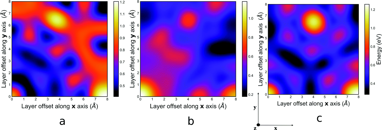 | ||
| Fig. 5 PES for the orbital energy contribution to the interaction energy for (a), the guest free system, (b) the mesitylene guest containing system, (c) and the benzene guest containing system of COF-1 computed at PBE-D3/TZ2P level of theory. An animation illustrating 3D structures that correspond to sample points on the PES can be viewed in the ESI† online at https://zenodo.org/record/6522043/files/Orbital_energy_contribution.mp4?download=1. | ||
The sum of the electrostatic and orbital energy represents the quantum-mechanical Coulomb interaction between polarised charge distributions for the two monomers, without any multipole approximation, and fully accounts for interpenetration of the monomer charge densities.49 The PES for this polarised Coulomb potential, which is represented in Fig. S4 in the ESI,† fully agrees with the Hunter and Sanders model that suggests that π–π interactions between stacked layers should always favour the slip-stacked configuration over the perfectly eclipsed configuration.50
3.5 Pauli energy contribution
The Pauli energy contribution contains the exchange and repulsion energies, which are stabilising and destabilising, respectively. The exchange interaction arises due to the antisymmetric nature of the wave function that allows the exchange of electrons between monomers, meanwhile the repulsion interaction originates from the interactions between electrons of the same spin on adjacent layers. The PES for the Pauli energy contribution to the interaction energy is presented in Fig. 6. For both systems, the Pauli interaction energy is nearly flat along all phenyl co-facial systems including the perfectly eclipsed system. | ||
| Fig. 6 PES for the Pauli energy contribution to the interaction energy for (a), the guest free system, (b) the mesitylene guest containing system, (c) and the benzene guest containing system of COF-1 computed at PBE-D3/TZ2P level of theory. An animation illustrating 3D structures that correspond to sample points on the PES can be viewed in the ESI† online at https://zenodo.org/record/6522043/files/Pauli_energy_contribution.mp4?download=1. | ||
The Pauli interaction energy fails to afford meaningful saddle point at the co-facial configuration in 2D COF systems. This result contradicts a recent study by Carter and Herbert.49 In this study, which was performed on benzene dimer, the authors suggested that the Pauli repulsion, rather than electrostatics, provides the driving force towards the slip-stacked arrangement. However, this discrepancy could be a consequence resulting from the underlying differences in Energy Decomposition Analysis (EDA) schemes51 or indicate that the results have limited applicability in describing π–π interaction of extended aromatic systems such as 2D COFs.52
3.6 Dispersion energy contribution
The dispersion energy contribution is defined here as the difference in correlation energy between the super-molecule and the individual monomer fragments. It takes into account all the long-range interactions and its accuracy depends on the density functional used. In this study, dispersion correction from the PBE functional is improved using the Grimme-D3 semi-empirical scheme.33 The PES for the dispersion energy contribution to the interaction energy is presented in Fig. 7. | ||
| Fig. 7 PES for the dispersion energy contribution to the interaction energy (a) for the guest free system, (b) the mesitylene guest containing system, (c) and the benzene guest containing system of COF-1 computed at PBE-D3/TZ2P level of theory. An animation illustrating 3D structures that correspond to sample points on the PES can be viewed in the ESI† online at https://zenodo.org/record/6522043/files/Disp_energy_contribution.mp4?download=1. | ||
The dispersion energy contribution to the total interaction energy is observed to favour the slip-stacked configuration over the perfectly eclipsed configuration in both the guest free and guest containing systems. In both systems, the shape of the PES for all the energy minima closely matches the shape of the GFN-xTB PES Fig. 2. In the guest free system, all energy minima below 0.4 eV are located within 4.0 Å meanwhile, the dispersion energy is significantly destabilised beyond this region. On the other hand, the presence of the guest molecule significantly stabilises the dispersion energy beyond this region consequently stabilising the AB configuration.
Finally, combining the dispersion energy with polarised Coulomb (Electrostatic + Orbital) energy provide a more sensible representation of the total interaction energy in comparison to the Pauli + dispersion energy as shown in Fig. S7 and S8 in the ESI.† This agrees with the classical Hunter and Sander models, which posit that π–π stacking in layered systems is governed by a competition between electrostatic and dispersion.50
4 Conclusion
In this study, we explored the different metastable stacking configuration at all possible lateral offsets for the guest free and guest containing systems of COF-1. We showed that the presence of the guest molecule leads to multiple low energy stacking configurations at significantly different lateral offsets, which are all experimentally feasible. Although COF-1 represents an extreme case where the effect of the guest molecule is critical in predicting the stacking configuration, we contend that these results can easily be applied to any COF or crystalline system. We contend that, likely guest molecules, arising from either incomplete activation or adsorption from the environment need to be considered in the comparison of computational and experimental PXRD patterns. In addition, we showed that care should be taken when using semi-empirical methods in simulating stacking configurations. Although these semi-empirical methods quite accurately account for dispersion, they still miss out on precisely capturing other important energy contributions that are critical for predicting the lateral offsets. Finally, we showed that π–π stacking in the 2D layered system is correctly governed by the simpler electrostatic vs. dispersion model posited by Hunter and Sander.Data availability
Coordinates and energies for the entire PES can freely be downloaded from https://doi.org/10.5281/zenodo.4058818.53 A python script to generate layer structures can be downloaded from https://github.com/bafgreat/Layer_builder.git. Videos illustrating the stacking configurations that correspond to sample points on all the PES generated in this study can freely be downloaded from https://doi.org/10.5281/zenodo.6522043.48Conflicts of interest
The authors declare no conflict of interest.Acknowledgements
MAA acknowledges an EPSRC New Investigator Award Grant no. EP/S015868/1. We acknowledge HPC resources on THOMAS via membership of the UK's HEC Materials Chemistry Consortium, which is funded by EPSRC (EP/P020194).References
- J. Ma, J. P. Sanchez, K. Wu, G. D. Couples and Z. Jiang, Fuel, 2014, 116, 498–508 CrossRef CAS.
- J. Wilkerson and K. Ramesh, J. Mech. Phys. Solids, 2016, 86, 94–116 CrossRef.
- Y. Fu, Z. Qu and L. Zhou, Energy Procedia, 2017, 105, 4769–4775 CrossRef CAS.
- H. Zhang, W. Fang, Z. Li and W. Tao, Int. Commun. Heat Mass Transfer, 2015, 68, 158–161 CrossRef CAS.
- E. Rafiee and S. Shahebrahimi, J. Mol. Struct., 2017, 1139, 255–263 CrossRef CAS.
- H. Zhang, W. Gu, M. Li, Z. Li, Z. Hu and W. Tao, Int. J. Heat Mass Transfer, 2014, 78, 947–959 CrossRef CAS.
- C. Forest, P. Chaumont, P. Cassagnau, B. Swoboda and P. Sonntag, Prog. Polym. Sci., 2015, 41, 122–145 CrossRef CAS.
- D. Bastani, N. Esmaeili and M. Asadollahi, J. Ind. Eng. Chem., 2013, 19, 375–393 CrossRef CAS.
- O. M. Yaghi, M. O'Keeffe, N. W. Ockwig, H. K. Chae, M. Eddaoudi and J. Kim, Nature, 2003, 423, 705–714 CrossRef CAS PubMed.
- O. Yaghi, M. O'Keeffe and M. Kanatzidis, J. Solid State Chem., 2000, 152, 1–2 CrossRef CAS.
- U. Mueller, M. Schubert, F. Teich, H. Puetter, K. Schierle-Arndt and J. Pastré, J. Mater. Chem., 2006, 16, 626–636 RSC.
- L. Hailian, M. Eddaoudi, M. O'Keeffe and O. Yaghi, Nature, 1999, 402, 276–279 CrossRef.
- A. C. Sudik, A. R. Millward, N. W. Ockwig, A. P. Côté, J. Kim and O. M. Yaghi, J. Am. Chem. Soc., 2005, 127, 7110–7118 CrossRef CAS PubMed.
- H. Hayashi, A. Cote, H. Furukawa, M. O'Keeffe and O. Yaghi, Nat. Mater., 2007, 6, 501–506 CrossRef CAS PubMed.
- A. P. Cote, H. M. El-Kaderi, H. Furukawa, J. R. Hunt and O. M. Yaghi, J. Am. Chem. Soc., 2007, 129, 12914–12915 CrossRef CAS PubMed.
- X. Liu, D. Huang, C. Lai, G. Zeng, L. Qin, H. Wang, H. Yi, B. Li, S. Liu, M. Zhang, R. Deng, Y. Fu, L. Li, W. Xue and S. Chen, Chem. Soc. Rev., 2019, 48, 5266–5302 RSC.
- H. M. El-Kaderi, J. R. Hunt, J. L. Mendoza-Cortés, A. P. Côté, R. E. Taylor, M. O'Keeffe and O. M. Yaghi, Science, 2007, 316, 268–272 CrossRef CAS PubMed.
- F. Haase, K. Gottschling, L. Stegbauer, L. S. Germann, R. Gutzler, V. Duppel, V. S. Vyas, K. Kern, R. E. Dinnebier and B. V. Lotsch, Mater. Chem. Front., 2017, 1, 1354–1361 RSC.
- Y.-B. Zhang, J. Su, H. Furukawa, Y. Yun, F. Gándara, A. Duong, X. Zou and O. M. Yaghi, J. Am. Chem. Soc., 2013, 135, 16336–16339 CrossRef CAS PubMed.
- J. Gao and D. Jiang, Chem. Commun., 2016, 52, 1498–1500 RSC.
- C. F. Holder and R. E. Schaak, ACS Nano, 2019, 13, 7359–7365 CrossRef CAS PubMed.
- Y. Du, D. Calabro, B. Wooler, Q. Li, S. Cundy, P. Kamakoti, D. Colmyer, K. Mao and P. Ravikovitch, J. Phys. Chem. C, 2014, 118, 399–407 CrossRef CAS.
- R. W. Tilford, W. R. Gemmill, H.-C. zur Loye and J. J. Lavigne, Chem. Mater., 2006, 18, 5296–5301 CrossRef CAS.
- X. Ding, L. Chen, Y. Honsho, X. Feng, O. Saengsawang, J. Guo, A. Saeki, S. Seki, S. Irle, S. Nagase, V. Parasuk and D. Jiang, J. Am. Chem. Soc., 2011, 133, 14510–14513 CrossRef CAS PubMed.
- E. L. Spitler, B. T. Koo, J. L. Novotney, J. W. Colson, F. J. Uribe-Romo, G. D. Gutierrez, P. Clancy and W. R. Dichtel, J. Am. Chem. Soc., 2011, 133, 19416–19421 CrossRef CAS PubMed.
- B. Lukose, A. Kuc and T. Heine, Chem. – Eur. J., 2011, 17, 2388–2392 CrossRef CAS PubMed.
- B. T. Koo, W. R. Dichtel and P. Clancy, J. Mater. Chem., 2012, 22, 17460–17469 RSC.
- S. Grimme, C. Bannwarth and P. Shushkov, J. Chem. Theory Comput., 2017, 13, 1989–2009 CrossRef CAS PubMed.
- B. P. Biswal, S. Valligatla, M. Wang, T. Banerjee, N. A. Saad, B. M. K. Mariserla, N. Chandrasekhar, D. Becker, M. Addicoat, I. Senkovska, R. Berger, D. N. Rao, S. Kaskel and X. Feng, Angew. Chem., Int. Ed., 2019, 58, 6896–6900 CrossRef CAS PubMed.
- Z. Meng, R. M. Stolz and K. A. Mirica, J. Am. Chem. Soc., 2019, 141, 11929–11937 CrossRef CAS PubMed.
- K. Dong, J. Liang, Y. Wang, L. Zhang, Z. Xu, S. Sun, Y. Luo, T. Li, Q. Liu, N. Li, B. Tang, A. A. Alshehri, Q. Li, D. Ma and X. Sun, ACS Catal., 2022, 10, 6092–6099 CrossRef.
- A. Jati, K. Dey, M. Nurhuda, M. A. Addicoat, R. Banerjee and B. Maji, J. Am. Chem. Soc., 2022, 144, 7822–7833 CrossRef CAS PubMed.
- S. Grimme, J. Antony, S. Ehrlich and H. Krieg, J. Chem. Phys., 2010, 132, 154104 CrossRef PubMed.
- M. Raupach and R. Tonner, J. Chem. Phys., 2015, 142, 194105 CrossRef PubMed.
- M. v Hopffgarten and G. Frenking, Wiley Interdiscip. Rev.: Comput. Mol. Sci., 2012, 2, 43–62 Search PubMed.
- Z. Tom and R. Arvi, Theor. Chim. Acta, 1977, 46, 1–10 CrossRef.
- K. Morokuma, J. Chem. Phys., 1971, 55, 1236–1244 CrossRef CAS.
- D. M. Andrada and C. Foroutan-Nejad, Phys. Chem. Chem. Phys., 2020, 22, 22459–22464 RSC.
- J. Thirman, E. Engelage, S. M. Huber and M. Head-Gordon, Phys. Chem. Chem. Phys., 2018, 20, 905–915 RSC.
- J. P. Perdew, K. Burke and M. Ernzerhof, Phys. Rev. Lett., 1996, 77, 3865–3868 CrossRef CAS PubMed.
- E. V. Lenthe and E. J. Baerends, J. Comput. Chem., 2003, 24(9), 1142–1156 CrossRef PubMed.
- D. Nazarian, P. Ganesh and D. S. Sholl, J. Mater. Chem. A, 2015, 3, 22432–22440 RSC.
- A. Kuc, M. A. Springer, K. Batra, R. Juarez-Mosqueda, C. Woll and T. Heine, Adv. Funct. Mater., 2020, 1908004 CrossRef CAS.
- G. te Velde, F. M. Bickelhaupt, E. J. Baerends, C. Fonseca Guerra, S. J. A. van Gisbergen, J. G. Snijders and T. Ziegler, J. Comput. Chem., 2001, 22, 931–967 CrossRef CAS.
- J. Sun, A. Iakunkov, I. A. Baburin, B. Joseph, V. Palermo and A. V. Talyzin, Angew. Chem., Int. Ed., 2020, 59, 1087–1092 CrossRef CAS PubMed.
- S.-T. Yang, J. Kim, H.-Y. Cho, S. Kim and W.-S. Ahn, RSC Adv., 2012, 2, 10179–10181 RSC.
- A. M. Evans, I. Castano, A. Brumberg, L. R. Parent, A. R. Corcos, R. L. Li, N. C. Flanders, D. J. Gosztola, N. C. Gianneschi, R. D. Schaller and W. R. Dichtel, J. Am. Chem. Soc., 2019, 141, 19728–19735 CrossRef CAS PubMed.
- A. D. D. Wonanke and M. A. Addicoat, Effect of Guest Molecules on the Stacking Configuration of Covalent Organic Frameworks: A Periodic Energy Decomposition Analysis, 2022 DOI:10.5281/zenodo.6522043.
- K. Carter-Fenk and J. M. Herbert, Phys. Chem. Chem. Phys., 2020, 22, 24870–24886 RSC.
- C. A. Hunter and J. K. M. Sanders, J. Am. Chem. Soc., 1990, 112, 5525–5534 CrossRef CAS.
- M. J. S. Phipps, T. Fox, C. S. Tautermann and C.-K. Skylaris, Chem. Soc. Rev., 2015, 44, 3177–3211 RSC.
- S. Grimme, Angew. Chem., Int. Ed., 2008, 47, 3430–3434 CrossRef CAS PubMed.
- A. D. D. Wonanke and M. A. Addicoat, Effect of Guest Molecules on the Stacking Configuration of Covalent Organic Frameworks: A Periodic Energy Decomposition Analysis, 2020 DOI:10.5281/zenodo.6520172.
Footnote |
| † Electronic supplementary information (ESI) available: Correlation of PBE-D3 and GFN-xTB interlayer heights for both guest free and guest containing structures of COF-1. Brief summary of the periodic energy decomposition analysis. Pictorial illustration of different stacking arrangements. Combinations of all contributions to the total interaction energy. PXRD and lattice parameters for all structures discussed. Lateral offset and interlayer heights for 100 minima. See DOI: https://doi.org/10.1039/d2cp00017b |
| This journal is © the Owner Societies 2022 |