
Quest: structure and properties of BTF–nitrobenzene cocrystals with different ratios of components†
Nikita M.
Baraboshkin
 *,
Victor P.
Zelenov
,
Mikhail E.
Minyaev
and
Tatyana S.
Pivina
*,
Victor P.
Zelenov
,
Mikhail E.
Minyaev
and
Tatyana S.
Pivina
N. D. Zelinsky Institute of Organic Chemistry, Russian Academy of Sciences, 47 Leninsky Prosp, Moscow 119991, Russian Federation. E-mail: nikitabaraboshkin@gmail.com
First published on 15th November 2021
Abstract
Using the methods of quantum chemistry and atom–atom potentials, the structure of benzotrifuroxan (BTF) cocrystals with nitrobenzenes (nitrobenzene, 1,2-, 1,3-, 1,4-dinitrobenzene, 1,3,5-trinitrobenzene, and hexanitrobenzene) with different ratios of components (1![[thin space (1/6-em)]](https://www.rsc.org/images/entities/char_2009.gif) :1, 1:2, 1:3 and in reverse order) is modeled. Based on the estimation of the energy of cocrystallization, a prediction was made of the possibility to obtain cocrystals, some of which were obtained and investigated by single-crystal XRD. For the first time, a cocrystal with three BTF molecules and one coformer molecule (1,4-DNB) in a unit cell was obtained. An analysis of the contacts of the crystal packing of the studied cocrystals shows that the polarizing effects of oxygen and nitrogen atoms in the BTF ring, which is a π system with a low electron content, form pseudo-hydrogen bonds and π–π interactions with nitro groups of coformers relatively rich in electrons, which leads to the formation of cocrystals. It was experimentally shown that the formation of cocrystals, in addition to the structural features of nitrobenzenes, is also influenced by thermodynamic factors (the polarity of the solvent and the ratio of the components used for cocrystallization).
:1, 1:2, 1:3 and in reverse order) is modeled. Based on the estimation of the energy of cocrystallization, a prediction was made of the possibility to obtain cocrystals, some of which were obtained and investigated by single-crystal XRD. For the first time, a cocrystal with three BTF molecules and one coformer molecule (1,4-DNB) in a unit cell was obtained. An analysis of the contacts of the crystal packing of the studied cocrystals shows that the polarizing effects of oxygen and nitrogen atoms in the BTF ring, which is a π system with a low electron content, form pseudo-hydrogen bonds and π–π interactions with nitro groups of coformers relatively rich in electrons, which leads to the formation of cocrystals. It was experimentally shown that the formation of cocrystals, in addition to the structural features of nitrobenzenes, is also influenced by thermodynamic factors (the polarity of the solvent and the ratio of the components used for cocrystallization).
1. Introduction
The creation of cocrystals of energetic compounds (ECs) made it possible not only to significantly expand the range of energetic materials but also to determine some trends of changes in their thermochemical and explosive characteristics in comparison to the initial components, which contributed to the active development of this field of chemistry in recent decades. For example, there is evidence1–10 that cocrystalline forms are less sensitive than their initial components, without a noticeable loss of energy properties. However, despite certain successes in the creation of high-energy cocrystals, at present, any obvious regularities between the structure of individual compounds and the features of the crystal packing of compositions based on them have not been determined. Moreover, clear relationships between the structure and the cocrystallization ability of components have not been revealed.The purpose of this work was to reveal the relationship between the structure of the parent compounds (by using substances of the same homologous series) and their ability to form cocrystals.
Benzotrifuroxan (BTF) was chosen as the main partner/component of the cocrystalline forms for a number of reasons. First, BTF has high thermal stability (Tm.p. ∼195 °C) and high crystal density (1.901 g cm−3), which is very important for ECs. Secondly, this compound has excellent complexing ability. It should be noted that the aromaticity of BTF, as a derivative of arene compounds, is considered to be completely impaired, i.e. close to no aromaticity. Nevertheless, the presence in the BTF molecule of three furoxan fragments with electron-acceptor properties and some aromaticity as well as a nucleus depleted in electron density, largely determines the ability of the compound to form donor–acceptor complexes with a large number of partners. A group of arenes containing only nitro groups in different positions of the aromatic nucleus was chosen as coformers for cocrystallization with BTF.
The first information about the formation of complexes of BTF with arenes was published by Bailey and Case in 1958.11 The authors obtained 7 complexes with benzene and its derivatives and 13 complexes with naphthalene as well as with indole and 3-phenyl-benzo[b]thiophene. Later, a number of complexes were supplemented with cocrystals of BTF with anthracene, pyrene, and perylene, and X-ray data on the structure of the complexes were obtained.12 The authors of this work believed that the key influences in the formation of cocrystals are the electron-donating properties of arenes and the electron-withdrawing properties of BTF.
However, relatively recently, BTF cocrystals were obtained with partner compounds that themselves possess electron-withdrawing properties: 2,4,6-trinitrotoluene (TNT),13 2,4,6-trinitrobenzene methylamine (MATNB),13 1,3,5-trinitrobenzene (TNB),13 trinitroazetidine (TNAZ),13 2,4,6-trinitroaniline (TNA),13 hexanitrohexaazaisowurtzitane (HNIW, CL-20),14 furazanotetrazine dioxide (FTDO),15 and cyanuric triazide.16 The formation of complexes of BTF with coformers that do not have pronounced electron-donor properties suggests a different mechanism of complexation, which had to be determined. In the obtained cocrystals, the formation of T-shaped complexes has attracted attention, which causes a strong electrostatic interaction between the electron-rich oxygen atoms of nitro groups and the uniform acceptor structure of the entire BTF molecule.
Previously, BTF cocrystals with TNB (1:1) and TNT (1:1) were obtained,13 and it was noted that cocrystallization led to a shortening of the bond between the N-oxide nitrogen atom of the furoxan cycle and the endocyclic oxygen atom, which, in many respects, according to the authors, is responsible for the key effect on an almost twofold decrease in the sensitivity of cocrystals, in comparison with individual BTF.
Most cocrystals of energetic compounds were obtained exclusively empirically without a preliminary theoretical assessment of the possibility of their formation. However, such a theoretical estimate can be performed using crystal structure prediction methods.15,17 This problem was formulated a long time ago, but its solution over the past decade has made significant progress, which is associated with advances in the field of parallel computing technologies as well as with the development of effective models for calculating intermolecular interactions, which made it possible to move to a new, higher level of modeling and predicting the structure of cocrystalline forms with an assessment of the possibility of their formation.18–20 In this work, the solution to this problem was carried out by modeling the structure based on scanning the potential energy surface (PES) of BTF and its partners (coformers), which are nitro-substituted arenes, and then their cocrystals with the identification of the most energetically favorable compositions. The Cambridge Crystallographic Database contains no data on the structure of cocrystals of nitrobenzenes with BTF except for the previously obtained cocrystal of BTF with TNB13 (CCDC number 882015).
It should be noted that the overwhelming majority of complexes presented in the literature contain only 1 molecule of an aromatic compound per BTF molecule, but there are also exceptions. For example, BTF with 1-phenyl-naphthalene forms a cocrystal in the ratio 3:2, and with p-nitrobenzaldehyde, 1:2. The identification of the structural parameters of the parent compounds, which determine the structural features of the complexes and change the ratio of the components in the composition of the cocrystal, was also the subject of our study.
It was important for us to experimentally confirm the results of the performed modeling, to obtain the structures of BTF complexes with nitroarenes predicted from the cocrystallization energies with different ratios of components, and to analyze the main motifs of their packing in order to understand the influence of the main structural and non-structural factors (the ratio of components taken for cocrystallization and the possible influence of the solvent) on the cocrystallization process.
A number of nitrobenzenes, which are of interest as energetic compounds, were chosen as coformers of cocrystals with BTF; in addition, it was useful to trace how, within one homologous series, the “accumulation” in the structure of compounds of nitro groups (from one to six) and the isomerism of positions (o-, m- and p-dinitrobenzene) affect the complexation process. In this way, the objects of the study of cocrystalline forms of BTF were benzene and its nitro derivatives (Fig. 1): benzene (1), nitrobenzene (2), o-, m-, and p-dinitrobenzene (3–5), 1,3,5-trinitrobenzene (6), and hexanitrobenzene (7).
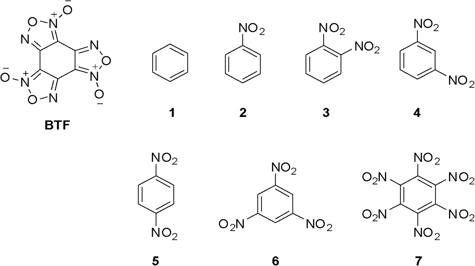 | ||
| Fig. 1 Benzotrifuroxan (BTF) and its cocrystal partners. | ||
2. Methodology and computational details
The geometry and electronic structure of cocrystals and their coformers were calculated within the framework of the density functional theory (DFT) method with the B3LYP/6-31G(d,p) functional using the Gaussian 09 software package.21 The localization of stable states of molecules on the PES was controlled by the absence of negative eigenvalues of the Hessian matrix.It is known that in modeling the structure of crystals for a correct description of electrostatic interactions, the quality of the molecular charge models is critically important, which is estimated by the accuracy of reproducing the dipole moment and the quadrupole moment.22 We selected the values of atomic charges in such a way that the electrostatic potential of the system of point charges outside the van der Waals surface of the molecule was the least different from the quantum chemical molecular electrostatic potential (MEP), for which we used the FitMEP software package.23 To construct the charge distribution of molecules, shifted charge (SC) models were used, in which both the magnitude of the charges and their position in the three-dimensional area around each molecule were optimized. To compare the quality of approximation of the MEP, the charge models SC and Mulliken were built (Table 1).
| Compounds | Charge model | DM,aD | Q xx | Q yy | Q zz | Q xy | Q xz | Q yz | R (kcal mol−1) | R rel (%) |
|---|---|---|---|---|---|---|---|---|---|---|
| a DM is the dipole moment (D). b Q xx , Qyy, Qzz, Qxy, Qxz, and Qyz are the molecular quadrupole moment components (Qxx + Qyy + Qzz = 0). c R is the root-mean-square deviation of the model IEP from the calculated quantum chemical value. d R rel is the relative root-mean-square error in the approximation of the MEP. | ||||||||||
| Benzene | Mulliken | 0 | 1.72 | 1.72 | −3.43 | 0 | 0 | 0 | 0.402 | 27 |
| SC | 0 | 2.36 | 2.36 | −4.72 | 0 | 0 | 0 | 0.029 | 1.95 | |
| QM | 0 | 2.36 | 2.36 | −4.73 | 0 | 0 | 0 | 0 | 0 | |
| Nitrobenzene (NB) | Mulliken | 6.40 | 1.21 | 4.95 | −6.16 | 0 | 0 | 0 | 2.24 | 48 |
| SC | 4.57 | −0.77 | 3.80 | −3.02 | 0 | 0.001 | 0 | 0.03 | 0.54 | |
| QM | 4.56 | −0.78 | 3.79 | −3.01 | 0 | 0 | 0 | 0 | 0 | |
| 1,2-Dinitrobenzene (1,2-DNB) | Mulliken | 10.26 | 2.97 | −4.18 | 1.20 | 0 | 0 | −1.69 | 4.16 | 61 |
| SC | 6.66 | 3.91 | −2.35 | −1.55 | 0 | 0 | −2.41 | 0.046 | 0.67 | |
| QM | 6.66 | 3.92 | −2.34 | −1.57 | 0 | 0 | −2.41 | 0 | 0 | |
| 1,3-Dinitrobenzene (1,3-DNB) | Mulliken | 6.10 | 11.46 | −23.23 | 11.78 | 0 | 0 | 0 | 2.86 | 55 |
| SC | 4.21 | 6.85 | −15.08 | 8.23 | 0 | 0 | 0 | 0.03 | 0.55 | |
| QM | 4.21 | 6.84 | −15.05 | 8.21 | 0 | 0 | 0 | 0 | 0 | |
| 1,4-Dinitrobenzene (1,4-DNB) | Mulliken | 0 | 14.82 | 16.91 | −31.73 | 0 | 0 | 0 | 2.62 | 64 |
| SC | 0 | 9.14 | 11.27 | −20.42 | 0 | 0 | 0 | 0.03 | 0.72 | |
| QM | 0 | 9.12 | 11.26 | −20.38 | 0 | 0 | 0 | 0 | 0 | |
| 1,3,5-Trinitrobenzene (1,3,5-TNB) | Mulliken | 0 | −11.63 | −11.63 | 23.27 | 0 | 0 | 0 | 2.98 | 67 |
| SC | 0 | −7.56 | −7.56 | 15.11 | 0 | 0 | 0 | 0.035 | 0.79 | |
| QMc | 0 | −7.55 | −7.55 | 15.09 | 0 | 0 | 0 | 0 | 0 | |
| Hexanitrobenzene (HNB) | Mulliken | 0 | 31.24 | −15.61 | −15.63 | 0 | 0 | 0 | 20.71 | 392 |
| SC | 0 | −5.81 | −5.82 | 11.63 | 0 | 0 | 0 | 0.07 | 1.85 | |
| QM | 0 | −5.80 | −5.83 | 11.63 | 0 | 0 | 0 | 0 | 0 | |
| Benzotrifuroxan (BTF) | Mulliken | 0 | −17.56 | −17.56 | 35.11 | 0 | 0 | 0 | 6.98 | 157 |
| SC | 0 | −7.35 | −7.35 | 14.69 | 0 | 0 | 0 | 0.05 | 1.17 | |
| QM | 0 | 1.72 | −7.32 | 14.64 | 0 | 0 | 0 | 0 | 0 | |
The quality of the approximation of the models can be judged by the root-mean-square deviation (R) of the model MEP from the calculated quantum chemical value as well as by comparing the calculated values of the dipole (DM) and quadrupole moments (Qxx, Qyy, Qzz, Qxy, Qxz, Qyz) with the quantum chemical calculations (model charges qj (j = 1, … n, where n is the number of charges) obey the electroneutrality condition (∑qj = 0); therefore only n – 1 of them are independent variables in the procedure for minimizing R).
Table 1 shows that for SC models the relative root-mean-square error (Rrel) in the approximation of the MEP is less than 1%, while for the Mulliken models it is tens of percent; therefore, we modeled the crystal packings of cocrystals and individual components based on the electrostatic SC models only.
When simulating the structure of cocrystals, the obtained molecular structures of BTF and nitrobenzenes with their MEPs were used to construct starting models of crystal lattices with further optimization by the method of atom–atom potentials24 according to the method presented in the literature.15,25 The crystal packing was simulated by optimizing the crystal unit cell with the localization of potential energy surface (PES) minima. Potential energy included van der Waals atom–atom potentials (EVdW) and electrostatic interactions (Ecoul):
| Ecomplex/lattice = EVdW + Ecoul = [−A/rij6 + Bexp−αrij] + qiqj/rij, | (1) |
To describe the non-covalent interactions, the FIT empirical “repulsion-dispersion” potentials were used,26 which were successfully tested and were selected for the best reproduction of the energies of the crystal lattices for H-, C-, N-, and O-containing compounds.
The generation of the starting models and the subsequent scanning of the PES were carried out using the PMC software package.27
Modeling of the crystal structure of cocrystals was carried out in the statistically most common space groups28,29 of molecular crystals: P21/c, P![[1 with combining macron]](https://www.rsc.org/images/entities/char_0031_0304.gif) , P212121, P21, C2/c, Pbca, C2, Pna21, Pnma, Cc, Pbcn, P1, and Pca21. The structural search for the global minimum of the PES occurred for cocrystals of BTF with nitrobenzene and with 1,4-dinitrobenzene in the ratios 1:1, 1:2, 1:3, 2:1, and 3:1; for cocrystals of BTF with 1,2- and 1,3-dinitrobenzenes in the ratios 1:1, 1:2, and 1:3; and for cocrystals of BTF with hexanitrobenzene in the ratio 1:1.
, P212121, P21, C2/c, Pbca, C2, Pna21, Pnma, Cc, Pbcn, P1, and Pca21. The structural search for the global minimum of the PES occurred for cocrystals of BTF with nitrobenzene and with 1,4-dinitrobenzene in the ratios 1:1, 1:2, 1:3, 2:1, and 3:1; for cocrystals of BTF with 1,2- and 1,3-dinitrobenzenes in the ratios 1:1, 1:2, and 1:3; and for cocrystals of BTF with hexanitrobenzene in the ratio 1:1.
During scanning, the molecules were presented as rigid bodies, the positions of which were set by fractional coordinates and three Euler angles. For the ten deepest PES minima of BTF–arene cocrystals, in order to avoid duplication of calculated crystal packings, the results were processed using the CRYCOM program.30 To visualize the intermolecular interactions in the crystals, the Hirshfeld surfaces were constructed in the form of a full-color map (2D fingerprint plots) using the program CrystalExplorer 17.5.31
The energy of cocrystallization was estimated by formula (2):
| ΔE = Ecocryst(BTF–arene) – Ecryst(BTF) – Ecryst(arene), | (2) |
3. Experimental section
3.1. Cocrystallisation of BTF with benzene and nitrobenzenes
The BTF–benzene solvate (1:1) was obtained by crystallization from a solution in benzene. 125 mg BTF in 9 ml benzene were heated to ∼60 ° C and left to cool to room temperature for gradual formation of cocrystals.
Solvate BTF–NB (1:1) was obtained in a similar way from a nitrobenzene solution. A portion of BTF (80 mg) was dissolved in ∼600 mg of nitrobenzene and heated to a temperature of ∼50 °C, then left to cool to room temperature. Crystals suitable for X-ray structural analysis were formed in about 1–2 h.
Cocrystallization of BTF with 1,4-DNB was performed as follows: to a mixture of components in a molar ratio of 1:2 (viz., 129 mg BTF and 172 mg 1,4-DNB) was added CH2Cl2 (8 ml) and heated with stirring to reflux. The resulting solution was quickly decanted and left to crystallize for 2 days. Methylene chloride partially volatilized, resulting in the formation of BTF cocrystals with 1,4-DNB in a ratio of 3:1.
During cocrystallization in methylene chloride, BTF and 1,3-DNB were taken in a stoichiometric ratio (similar to the crystallization of BTF with 1,4-DNB), and in addition to the formation of cocrystals, the formation of individual BTF crystals was observed, which was established by X-ray diffraction data. A similar result was obtained during cocrystallization from a solution in methanol using the stoichiometric ratio of the components (compare with literature data32). In this regard, we performed cocrystallization of the components taken in a ratio of 1:1.5 (252 mg of each of the compounds) from 10 ml of methanol. The mixture was heated with stirring to 45–50 °C, filtered, and left to crystallize for several days with gradual volatilization of the solvent. As a result, only cocrystals of BTF with 1,3-DNB in a ratio of 1:1 were obtained.
3.2. Single-crystal X-ray diffraction
X-ray diffraction data were collected at 100 K on a Bruker Quest D8 diffractometer equipped with a Photon III area detector (shutterless ω-scan technique), using graphite-monochromatized Mo Kα radiation. The intensity data were integrated by the SAINT program33 and were semi-empirically corrected from equivalent reflections for absorption and decay using SADABS.34 The structures were solved by intrinsic methods using SHELXT35 and refined by full-matrix least-squares on F2 using SHELXL-2018.36 All non-hydrogen atoms were refined with anisotropic displacement parameters. Hydrogen atoms were placed in ideal calculated positions and refined as riding atoms with relative isotropic displacement parameters. Crystal data, data collection and structure refinement details for complexes BTF–NB, BTF–1,3-DNB and BTF–1,4-DNB are summarized in Table 2.| Cocrystal | BTF–NB | BTF–1,3-DNB | BTF–1,4-DNB |
|---|---|---|---|
| For all experiments: collection temperature is 100(2) K, radiation wavelength is 0.71073 Å (Mo Kα). | |||
| Empirical formula | C12H5N7O8 | C12H4N8O10 | C24H4N20O22 |
| Formula weight | 375.23 | 420.23 | 924.47 |
| Crystal system | Monoclinic | Monoclinic | Triclinic |
| Space group | P21/n | P21/c |
P |
| Unit cell dimensions | |||
| a/Å | 6.55650(10) | 7.1886(8) | 12.0783(3) |
| b/Å | 17.6948(4) | 17.2834(19) | 12.3615(3) |
| c/Å | 12.4912(3) | 12.4782(14) | 12.6822(3) |
| α/° | 90 | 90 | 107.0530(10) |
| β/° | 102.3351(6) | 94.337(3) | 95.2610(10) |
| γ/° | 90 | 90 | 112.0210(10) |
| Volume/Å3 | 1415.72(5) | 1545.9(3) | 1634.20(7) |
| Z | 4 | 4 | 2 |
| Density (calcd)/g cm−3 | 1.760 | 1.806 | 1.879 |
| μ/mm−1 | 0.152 | 0.161 | 0.170 |
| F(000) | 760 | 848 | 928 |
| θ range/° | 2.027 to 34.979 | 2.017 to 32.496 | 1.901 to 35.498 |
| Index ranges | −10 ≦ h ≦ 10, −28 ≦ k ≦ 28, −20 ≦ l ≦ 20 | −10 ≦ h ≦ 10, −26 ≦ k ≦ 26, −18 ≦ l ≦ 18 | −19 ≦ h ≦ 19, −20 ≦ k ≦ 20, −20 ≦ l ≦ 20 |
| Reflections | |||
| Collected | 42941 |
58873 |
89510 |
| Independent [Rint] | 6224 [0.0352] | 5587 [0.0732] | 14938 [0.0338] |
| Observed (I > 2σ(I)) | 4902 | 4261 | 10773 |
| Completeness to θmax | 0.999 | 0.999 | 0.999 |
| Data, restraints, parameters | 6224, 1037, 437 | 5587, 1101, 474 | 14938, 828, 934 |
| Goodness of fit on F2 | 1.039 | 1.068 | 1.093 |
| Final R1, wR2 indices (I > 2σ(I)) | 0.0628, 0.1475 | 0.0802, 0.2155 | 0.0696, 0.1803 |
| Final R1, wR2 indices (all data) | 0.0813, 0.1623 | 0.1003, 0.2348 | 0.0981, 0.2040 |
| Largest diff. peak, hole/e Å−3 | 0.461, −0.445 | 0.586, −0.626 | 0.859, −0.486 |
| CCDC deposition number | 2095321 | 2095322 | 2095323 |
The crystal structures of the three studied complexes (BTF–NB, BTF–1,3-DNB and BTF–1,4-DNB) were determined by X-ray single-crystal diffraction methods, although their solution and refinement exhibited certain difficulties. Thus, the decay of reflection intensities for the studied crystals resembled that for twinned crystals, but the obvious non-merohedral twinning was not detected in all three cases. Twin laws for possible pseudo-merohedral twinning were not determined. Therefore, the crystals were treated, solved and refined as monocrystals, in which the BTF molecule is highly disordered over several positions. Non-chiral (Pn), chiral (P21) and centrosymmetric (P21/n, P21/c) space groups were tried to model the structures of BTF–NB and BTF–1,3-DNB; P1 and P were considered for BTF–1,4-DNB. Slightly better models were obtained for the centrosymmetric space groups (Table 2) with a highly disordered BTF molecule in all cases. The high degree of the BTF disorder within the crystals might be due to the presence of similar non-covalent contacts between BTF and the solvent molecule that are very close in energy.
4. Results and discussion
4.1. Force-field validation for cocrystal structure prediction
To assess the quality of the method used for predicting the structure of cocrystals and the possibility of its use, we first modeled the crystal packings of individual nitroarenes, previously studied experimentally. Structural search was carried out in experimental space groups. In all cases, the simulated crystal packings of nitrobenzenes and BTF, corresponding to the deepest PES minima, coincided with the experimentally investigated crystal packings (Table 3).| Compounds | NB | 1,2-DNB | 1,3-DNB | 1,4-DNB | 1,3,5-TNB | HNB | BTF |
|---|---|---|---|---|---|---|---|
| Hereinafter:a E is the lattice energy; a, b, c (Å), α, β, γ (°) are the unit cell (u.c.) parameters; ρ is the molecular crystal density. The experimental data from the Cambridge Structural Database are given in parentheses.b The experimental values of sublimation enthalpy are given from the National Institute of Standards and Technology database.c The values of density, given in brackets, are taken from the literature.32,37d The experimental values of sublimation enthalpy for BTF are from ref. 38. | |||||||
| Experimental dataa | |||||||
| Space group | P21/c | P21/c | Pna21 | P21/n | P21/c | I2/c | Pna21 |
| a, Å | 3.80 | 7.94 | 14.08 | 5.66 | 12.89 | 13.22 | 6.92 |
| b, Å | 11.62 | 12.97 | 13.29 | 5.37 | 5.72 | 9.13 | 19.51 |
| c, Å | 12.98 | 7.42 | 3.80 | 10.91 | 11.28 | 9.68 | 6.51 |
| α, ° | 90 | 90 | 90 | 90 | 90 | 90 | 90 |
| β, ° | 95 | 111.9 | 90 | 92.0 | 98.2 | 95.5 | 90 |
| γ, ° | 90 | 90 | 90 | 90 | 90 | 90 | 90 |
| Sublimation enthalpy,b kcal mol−1 | 15.9 | 22.8 | 20.8 | 22.5 | 25.6 | — | 40.1 (25.6)d |
| ρ,c g cm−3 | 1.43 | 1.64 | 1.62 (1.57) | 1.68 | 1.72 | 1.98 (1.97) | 1.90 |
| Predicted structuresa | |||||||
| a, Å | 3.86 | 7.96 | 14.23 | 5.66 | 12.78 | 13.20 | 6.69 |
| b, Å | 11.87 | 13.03 | 13.52 | 5.37 | 6.03 | 8.954 | 19.91 |
| c, Å | 12.95 | 7.10 | 3.68 | 10.91 | 11.16 | 9.786 | 6.61 |
| α, ° | 90 | 90 | 90 | 90 | 90 | 90 | 90 |
| β, ° | 93 | 110.9 | 90 | 92.0 | 102.4 | 96 | 90 |
| γ, ° | 90 | 90 | 90 | 90 | 90 | 90 | 90 |
| E, kcal mol−1 | −15.6 | −22.71 | −22.76 | −22.64 | −23.51 | −30.55 | −25.63 |
| ρ, g cm−3 | 1.38 | 1.62 | 1.58 | 1.67 | 1.68 | 2.09 | 1.90 |
As follows from the simulation results (Table 3), the predicted crystal packing and unit cell parameters as well as the enthalpies of sublimation of the nitrobenzenes under consideration (Elattice ≈ −ΔHsublimation) are in good agreement with the experimental data. Consequently, the methods developed by us and the software systems used (see the Methodology and computational details section) can also be used to predict the structure of cocrystals and estimate their cocrystallization energies.
4.2. Estimation of the cocrystallization energy
The possibility of cocrystallization of BTF with benzene and nitroarenes was estimated using the cocrystallization energy value (formula (2)). The results of this estimation are presented in Table 4.| ΔEcocryst (kcal mol−1) | |||||
|---|---|---|---|---|---|
| Cocrystal ratios of components | 1:1 |
1:2 |
1:3 |
2:1 |
3:1 |
| a ΔEcocryst is the cocrystallization energy of simulated molecular packings. | |||||
| BTF–benzene | −4.33 | — | — | — | — |
| BTF–NB | −1.68 | −2.18 | −3.28 | −2.03 | 0.29 |
| BTF–1,2-DNB | 0.61 | 3.64 | 6.91 | 1.97 | 4.05 |
| BTF–1,3-DNB | 0.79 | 3.37 | 8.75 | 1.43 | 2.84 |
| BTF–1,4-DNB | 1.09 | 3.47 | 3.30 | 1.29 | −0.91 |
| BTF–1,3,5-TNB | −1.31 | 2.20 | 0.52 | — | — |
| BTF–HNB | 0.5 | — | — | — | — |
As follows from the calculated data, during cocrystallization of BTF with nitrobenzene, the formation of cocrystals with the ratios 1:1, 1:2, 1:3 and 2:1 is energetically favorable. Apparently, the key role in the possibility of formation of these compositions should be played by the thermodynamic factors of the cocrystallization process itself (temperature gradient, cooling rate, solvent used, multiple excess of one of the components). We have experimentally obtained and investigated the cocrystal (see section 4.2.2) in a 1:1 ratio of components. The formation of cocrystals of BTF with 1,3,5-TNB in a ratio of 1:1 is also energetically advantageous.
According to calculations (Table 4), the formation of the remaining cocrystalline forms of BTF with the considered nitrobenzenes is disadvantageous, since the calculated values of the enthalpy of cocrystallization lie in the region of positive values, which corresponds to the absence of an energy gain during cocrystallization. However, the successful preparation by us of the BTF–1,3-DNB (1:1) cocrystal using an excess of nitroarene indicates that thermodynamic and entropy factors, for example, the effect of the solvent used, can significantly change the crystallization pattern.
Obtaining a cocrystal of BTF with HNB, according to our calculations, turned out to be energetically unfavorable; therefore, due to the highly explosive nature of HNB and the ease of its hydrolytic decomposition, we did not attempt to obtain this cocrystal.
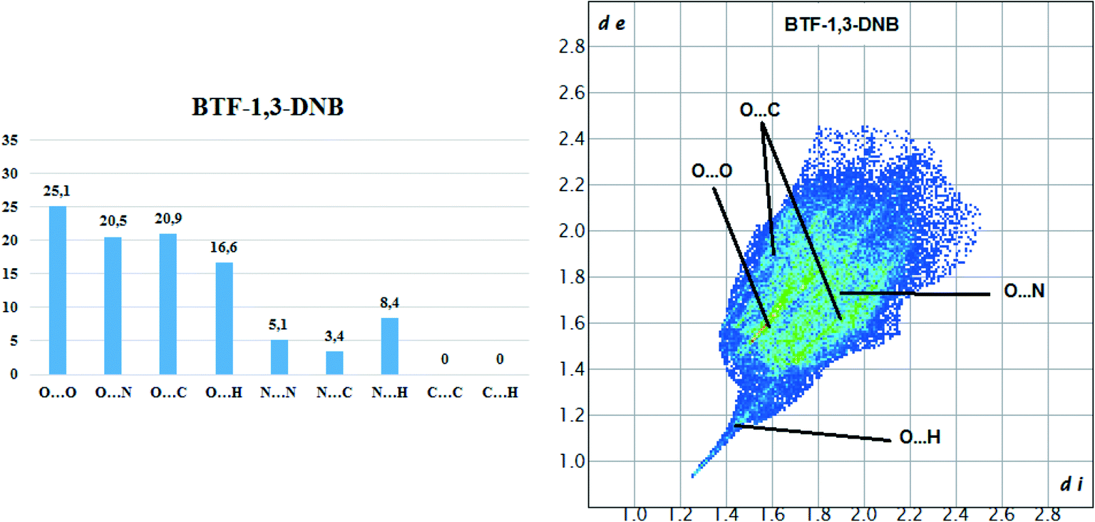
In this paper, we discuss the structure of only those simulated cocrystals for which experimental confirmation of their structure was obtained by X-ray structural analysis ((BTF–NB (1:1), BTF–1,3-DNB (1:1), BTF–1,4-DNB (3:1)) and previously obtained cocrystals of BTF (BTF–1,3-DNB (1:1)32) and BTF–1,3,5-trinitrobenzene (1:1)13). All other simulated but not experimentally obtained packages with different ratios of components in cocrystals are presented in the ESI.†
![[thin space (1/6-em)]](https://www.rsc.org/images/entities/b_char_2009.gif) :1.
First, we simulated the structure of the BTF cocrystal with benzene. Earlier, Boeyens et al.39 presented the structural parameters of the unit cell of the BTF–benzene solvate. However, the solvate crystal is a “twin”, where BTF molecules are disordered in the unit cell. The authors did not succeed in obtaining a structure of the proper quality; therefore, in the experimental structure of the solvate at the Cambridge Database (CCDC number 1319292), the coordinates of the atoms in the unit cell are absent. Due to the strongly disordered molecules in the BTF–benzene solvate, we also failed to obtain an acceptable crystallographic model. It is important to note that this solvate is formed only when BTF was dissolved in benzene, i.e. only when a significant excess of one of the two coformers was used. Upon cocrystallization of BTF–benzene taken in a ratio of 1:3 from a solution in methanol, crystallization of individual BTF was observed.
:1.
First, we simulated the structure of the BTF cocrystal with benzene. Earlier, Boeyens et al.39 presented the structural parameters of the unit cell of the BTF–benzene solvate. However, the solvate crystal is a “twin”, where BTF molecules are disordered in the unit cell. The authors did not succeed in obtaining a structure of the proper quality; therefore, in the experimental structure of the solvate at the Cambridge Database (CCDC number 1319292), the coordinates of the atoms in the unit cell are absent. Due to the strongly disordered molecules in the BTF–benzene solvate, we also failed to obtain an acceptable crystallographic model. It is important to note that this solvate is formed only when BTF was dissolved in benzene, i.e. only when a significant excess of one of the two coformers was used. Upon cocrystallization of BTF–benzene taken in a ratio of 1:3 from a solution in methanol, crystallization of individual BTF was observed.
To clarify the crystal structure of this solvate, we scanned the PES in the space group P21/c, indicated in ref. 37. The modeled crystal packing of the BTF–benzene solvate was in good agreement in the unit cell parameters with the experimental data37 (Table 5). The main interaction in the crystal packing of this solvate is a strong π–π stacking interaction between the BTF molecule and the benzene molecule, which apparently gives a large gain in cocrystallization energy (−4.33 kcal mol−1, Table 4).
:1) solvate
| a, Å | b, Å | c, Å | α, ° | β, ° | γ, ° | ρ, g cm−3 | E, kcal mol−1 | |
|---|---|---|---|---|---|---|---|---|
| Calculated | 13.81 | 7.36 | 14.80 | 90 | 115 | 90 | 1.61 | −41.13 |
| Experimental | 13.75 | 7.36 | 15.30 | 90 | 116 | 90 | 1.59 | — |
To compare the simulated packing with the experimental structure, we performed an X-ray diffraction experiment of the solvate obtained by us (Table 5). In the experimental structure, disordering of BTF molecules over two positions with equal statistical weights is observed. For comparison, Fig. 2 shows the projections of simulated (top) and experimental (bottom) crystalline packings of the solvate.
 | ||
| Fig. 2 Unit cell projection from the [101] side of the simulated (top) and experimental (bottom) crystal packing of the BTF–benzene (1:1) solvate. | ||
We tried to determine the structure of the BTF–benzene cocrystal (P21/c; a = 13.6970(10), b = 7.1953(5), c = 15.0055(11) Å, β = 116.552(2)°). However, due to a high degree of the BTF disorder, all components of which are located within the same plane, the collected X-ray data did not allow us to definitely determine all atom positions even for major components of the BTF disorder. We found that the benzene molecule is parallel to the BTF plane with the distance between planes of 3.3 Å.
:1).
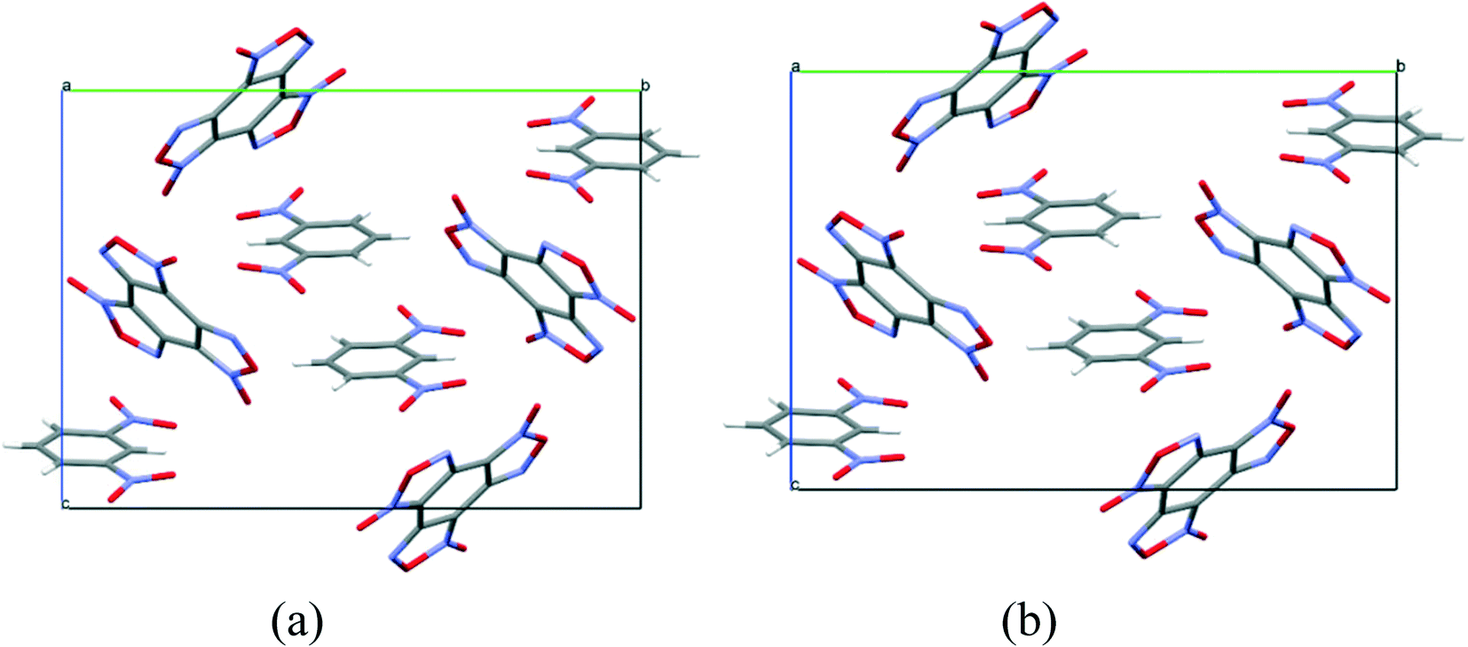
The structure of the BTF cocrystal with nitrobenzene with the component ratio 1:1, corresponding to the global minimum of the PES, was found in the space group P21/c, Z = 4 with lattice energy E = −42.95 kcal mol−1 (see the ESI†) and molecular crystal density 1.72 g cm−3. As can be seen from the projection of the unit cell, presented in Fig. 3, the calculated structure coincides with the experimental one (see Table 6).
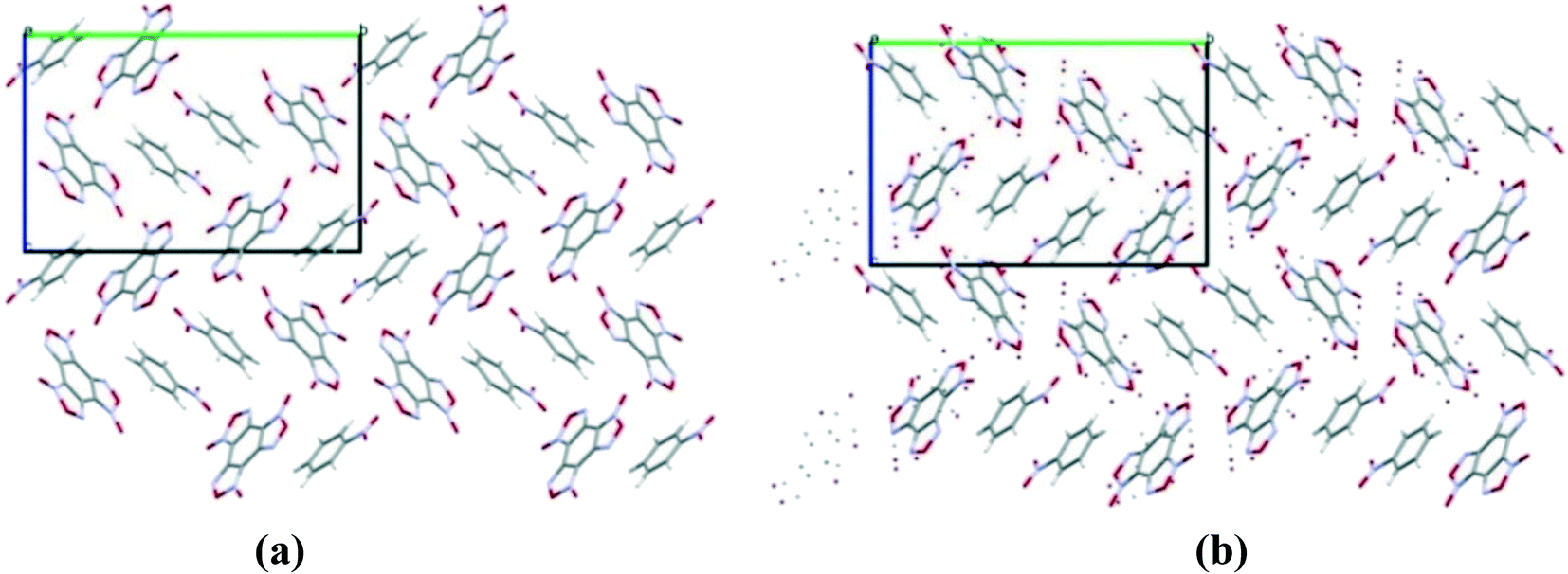 | ||
| Fig. 3 Simulated (a) and experimental (b) packing of the BTF cocrystal with nitrobenzene (1:1). Projection from the [101] side. | ||
:1) cocrystal
| a, Å | b, Å | c, Å | α, ° | β, ° | γ, ° | ρ, g cm−3 | E, kcal mol−1 | |
|---|---|---|---|---|---|---|---|---|
| Calculated | 6.41 | 18.70 | 12.58 | 90 | 104 | 90 | 1.72 | −42.95 |
| Experimental | 6.55 | 17.70 | 12.49 | 90 | 102 | 90 | 1.76 | — |
In the calculated and experimental structure, the main motif of the cocrystal packing is formed by T-shaped molecular complexes, namely by interaction between the oxygen atoms of the nitro groups saturated with electron density and the carbon atoms of the BTF nucleus depleted in electrons. Such T-shaped complexes are quite typical for BTF cocrystals with various nitro derivatives, both with alicyclic compounds (HNIW (CL-20),14 TNAZ13), and with aromatic structures (TNB, TNT, TNA, and MATNB).13 It should be noted that a plane-parallel complex is observed in the crystal between nitrobenzene molecules lying near the center of symmetry. Previously, the formation of such a complex was predicted by high-level quantum chemical calculations using the CCSD(T) method.40 The set of T-shaped complexes formed by the interaction of O(NO2)⋯C(BTF) and the plane-parallel dimer of nitrobenzene formed due to dispersion interactions, as well as the presence of π–π stacking interactions between the furoxan ring and nitrobenzene, determines the general packing motif in the BTF–nitrobenzene (1:1) cocrystal.
Although according to the results of calculations (see the ESI,† Table S3) the formation of other BTF–nitrobenzene cocrystals with the ratios 1:2, 1:3, and 2:1 is also energetically favorable, we experimentally obtained only cocrystal 1:1, most likely due to a significant excess of nitroarene taken as a solvent and some other non-structural factors. The coordinates of atoms in simulated crystal packings corresponding to the deepest minima for each component ratio as well as the projection of their crystal packings are presented in the ESI.†
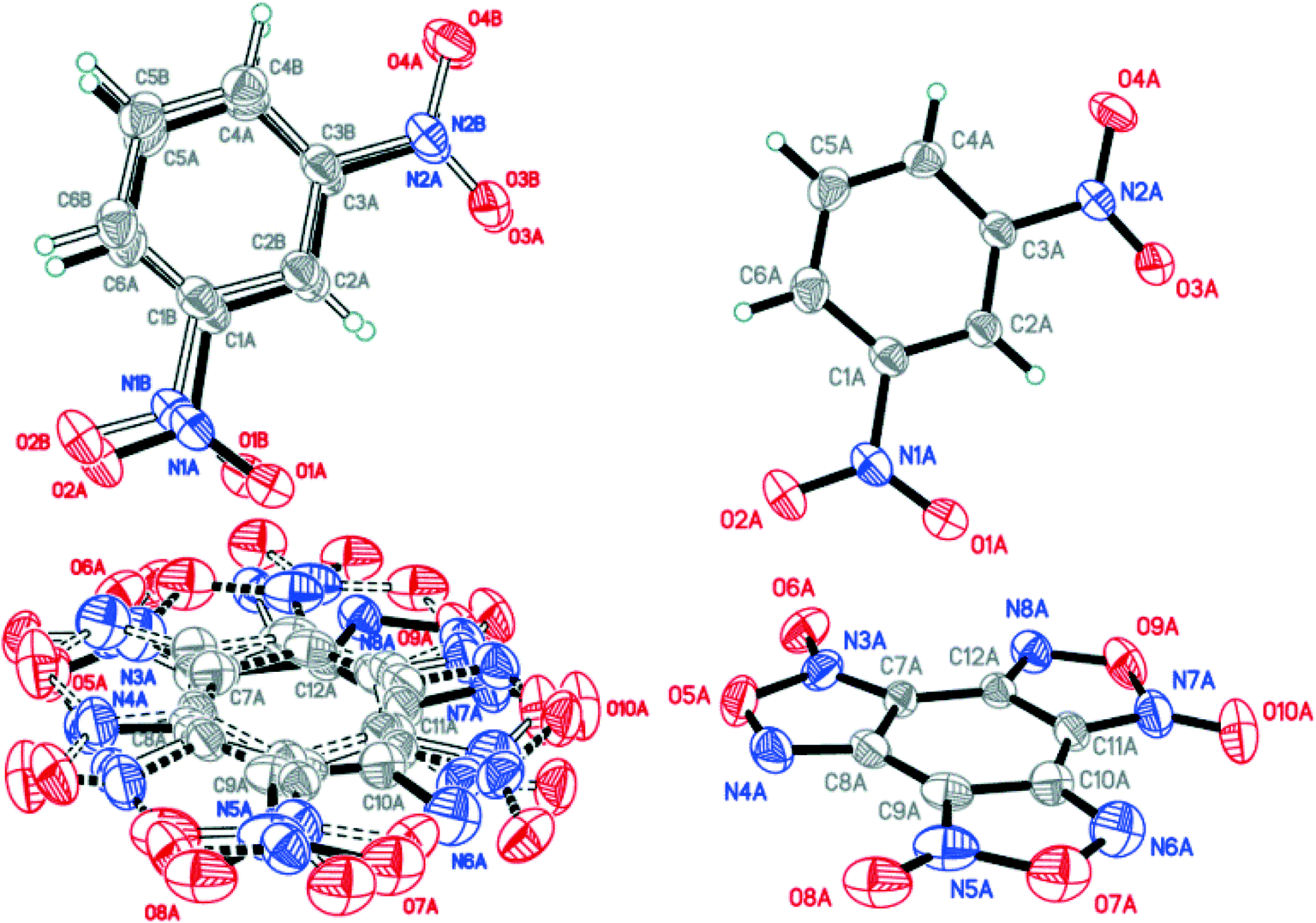
X-ray diffraction analysis of the obtained BTF–NB cocrystal (1:1) showed that BTF molecules in its structure are disordered over two major (A and B) and two minor (C and D) positions with the disorder ratio of 0.4491(12):0.4737(11):0.0414(12):0.0358(12) for A, B, C and D, respectively (Fig. 4). The major components A and B were routinely found from the electron density difference map (e-map). The starting coordinates for component C (or D) were obtained by inversion of the atom coordinates of component A (or B) against the centroid C1A⋯C6A (or C1B⋯C6B).
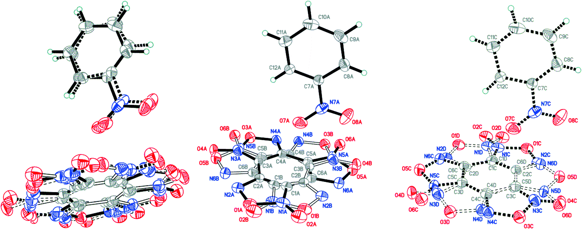 | ||
| Fig. 4 Crystal structure of BTF–NB (1:1) cocrystal (left), which may be split into two disorder components (middle and right) (p = 50%). | ||
Due to intermolecular short O⋯O contacts, the nitrobenzene molecule is also disordered over 2 positions: position A (occupancy 0.9228) corresponds to positions A and B of the BTF molecule (Fig. 4, middle), whereas position C of nitrobenzene (occupancy 0.0772) corresponds to positions A and B of the BTF molecule (Fig. 4, right). To describe short contacts, we considered the structure A of nitrobenzene and one of the major atom positions A of the BTF molecule.
In the cocrystal structure the shortest contacts are formed between the hydrogen atoms of the nitrobenzene molecule and the oxygen atoms of the furoxan cycle. The distances for these contacts vary from 2.498 Å to 2.664 Å. The shortest contact in the T-shaped complex is observed for C6A(BTF)⋯O7A(NB). Its length is 2.905 Å. The O7A(NB) atom interacts with the C5A and C1A(BTF) atoms with short contacts of 3.023 Å and 3.047 Å, respectively. O⋯O contacts (2.993 Å) are formed between BTF molecules with the participation of exocyclic and endocyclic oxygen atoms of the furoxan ring as well as between the oxygen of the nitro group and the endocyclic oxygen of the furoxan fragment (2.930 Å). The longest contacts are characteristic of π-stacking interactions C2A⋯C9A and C1A⋯C10A with lengths of 3.385 Å and 3.389 Å.
Hirshfeld surface analysis (Fig. 5) was performed for the A and B orientations of the BTF molecule in the BTF–NB co-crystal (1:1).
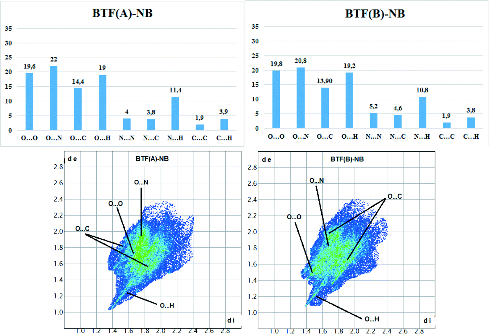 | ||
| Fig. 5 Results of calculation of 2D fingerprint plots for two major positions A and B of the BTF molecule in cocrystal BTF–NB (1:1). | ||
According to the constructed 2D fingerprint plots, the most significant are O⋯O, O⋯N, O⋯H contacts. A large proportion of O⋯O and O⋯N contacts on the surface are due to interactions of furoxan rings neighboring BTF molecules. O⋯H contacts are formed by the interactions of nitrobenzene with BTF.
:1) or (1:2) in CH2Cl2 solution from components taken in the ratio 1:2 did not lead us to obtain the cocrystals.
Earlier, Yang and colleagues reported32 about the preparation of BTF–1,3-DNB cocrystal in the ratio 1:1. However, the data associated with the article, presented by the authors in the Cambridge Crystallographic Data Centre (CCDC), did not correspond to 1,3-dinitrobenzene but to trinitrotoluene. Our modeling of the structure of this cocrystal revealed the most favorable packings in the space group P21/c, which coincides with the space group indicated in the article; however, the unit cell parameters stated in the article are very different from the calculated ones. In addition, the absence of a single-crystal X-ray diffraction structural data file presented by the authors in the CCDC raises doubts about the quality of the study. A visual comparison of the experimental packing32 indicates a similarity with the crystal packing that we predicted for the BTF–1,3-DNB (1:1) cocrystal with a lattice energy of −47.60 kcal mol−1 (Table 7).
:1) cocrystal modeled (calculated) with the experimental data22
| a, Å | b, Å | c, Å | α, ° | β, ° | γ, ° | ρ, g cm−3 | E, kcal mol−1 | |
|---|---|---|---|---|---|---|---|---|
| Calculated | 7.41 | 17.62 | 12.20 | 90 | 93 | 90 | 1.72 | −47.60 |
| Experimental | 7.18 | 17.28 | 12.48 | 90 | 94 | 90 | 1.76 | — |
| XRD31 | 9.36 | 13.00 | 14.91 | 90 | 96 | 90 | 1.74 | — |
To obtain the BTF–1,3-DNB (1:1) cocrystal and to study it by the SXRD method, we performed cocrystallization of BTF with 1,3-DNB from methanol in accordance with a known procedure.32 At a stoichiometric ratio of the components, the obtained BTF–1,3-DNB cocrystals (1:1) contained an impurity of crystalline BTF, whereas upon cocrystallization of the components taken in a ratio of 1:1.5, we obtained only BTF–1,3-DNB cocrystals (1:1). It is important to note that the cocrystallization of these components, taken in the ratio 1:2 from a solution of less polar methylene chloride, did not lead to the formation of cocrystals. The crystalline phase was only BTF. Thus, we have clearly demonstrated the effect of the solvent and ratio of coformers used on the cocrystallization process.
The structure predicted by us was successfully confirmed by XRD studies. Comparison of the unit cell parameters of the experimental and calculated crystal packings are presented in Table 7. Due to disordering, the packing with the highest statistical weight was taken as the experimental one.
In the BTF–1,3-DNB (1:1) cocrystal, the BTF molecule is also disordered over four positions A/B/C/D with the disorder ratio of 0.6532(17):0.2745(16):0.0474(16):0.0249(15) (Fig. 7, left). Major atom positions A and B were routinely found from the e-map. Minor positions C and D were determined by inversion of atom position sets A/B via centroids C7A⋯C12A/C7B⋯C12B, which provided the best crystallographic model for the studied crystal. 1,3-Dinitrobenzene is also disordered over two positions (A and B). The major disorder components of BTF (position set A) and of 1,3-DNB (component A) are considered below (Fig. 7, middle).
As in the case of the cocrystal with nitrobenzene, T-shaped complexes between BTF and 1,3-dinitrobenzene prevail in the packing motif, in which the nitro group is practically perpendicular to the plane of the BTF molecule (Fig. 6). The 1,3-DNB molecule, reflected in the center of symmetry, forms a complex and interacts with other 1,3-DNB molecules in a π–π stacking manner with the shortest C1A⋯C5A contacts of 3.381 Å length. Such a complex is surrounded by BTF molecules, which interact with 1,3-DNB through the formation of pseudo-hydrogen bonds with the contact lengths, respectively, of O8A(BTF)⋯H2A(1,3-DNB) 2.332 Å, O5A(BTF)⋯H6A(1,3-DNB) 2.668 Å, and O6A(BTF)⋯H4A(1,3-DNB) 2.704 Å. The formation of contacts between positively charged carbon atoms of BTF and negatively charged oxygen atoms of 1,3-DNB nitro groups is also characteristic: C7A(BTF)⋯O1A(1,3-DNB) 2.964 Å, C12A(BTF)⋯O1A(1,3-DNB) 3.138 Å, C7A(BTF)⋯O4A(1,3-DNB) 3.169 Å, C12A(BTF)⋯O4A(1,3-DNB) 3.144 Å, C7A(BTF)⋯O3A(1,3-DNB) 3.151 Å, and C8A(BTF)⋯O3A(1,3-DNB) 3.195 Å (Fig. 7).
 | ||
| Fig. 6 Projection of BTF–1,3-dinitrobenzene (1:1) cocrystal packings from the [011] side. (a) Experimental packing and (b) calculated packing corresponding to the global minimum of the PES. | ||
 | ||
| Fig. 7 Crystal structure of BTF–1,3-DNB (1:1) cocrystal (left) and major component of the disorder (right) (p = 50%). T-shaped molecular complex in crystal packing of BTF–1,3-DNB. | ||
Hirshfeld surface analysis of the BTF molecule in the cocrystal with 1,3-DNB indicates the predominance of short contacts O⋯O, O⋯N, and O⋯C (Fig. 8).
 | ||
| Fig. 8 Results of 2D fingerprint plot calculation for BTF molecule in cocrystal BTF–1,3-DNB (1:1). | ||
Compared with nitrobenzene, the intensity of O⋯H contacts decreases, while for C⋯O interactions it increases, which is apparently associated with a decrease in the number of available sites for the formation of O⋯H bonds. However, in comparison with another BTF–nitrobenzenes cocrystals the formed O⋯H contacts in BTF–1,3-DNB cocrystal (1:1) have lower (di and de) values, which is associated with a high positive charge on the H2A atom (1,3-DNB). Contacts C⋯O are formed between the BTF molecule and the 1,3-DNB nitro groups.
The BTF–1,3-DNB cocrystal is formed mainly due to O(DNB)⋯C(BTF) and the presence of pseudo-hydrogen bonds. The asymmetric unit of the BTF–1,4-DNB cocrystal (3:1) contains three non-equivalent BTF molecules (Fig. 9, top left), which are disordered at least over two positions each, and one 1,4-DNB molecule. The 1,4-DNB molecule forms short contacts mainly with one BTF molecule (Fig. 9, top right). Although the second BTF molecule was modeled as disordered over two positions (Fig. 9, bottom left), this molecule is likely disordered over 3 (or even 4) positions, but the residual electron density does not allow us to definitely determine the remaining minor position(s).
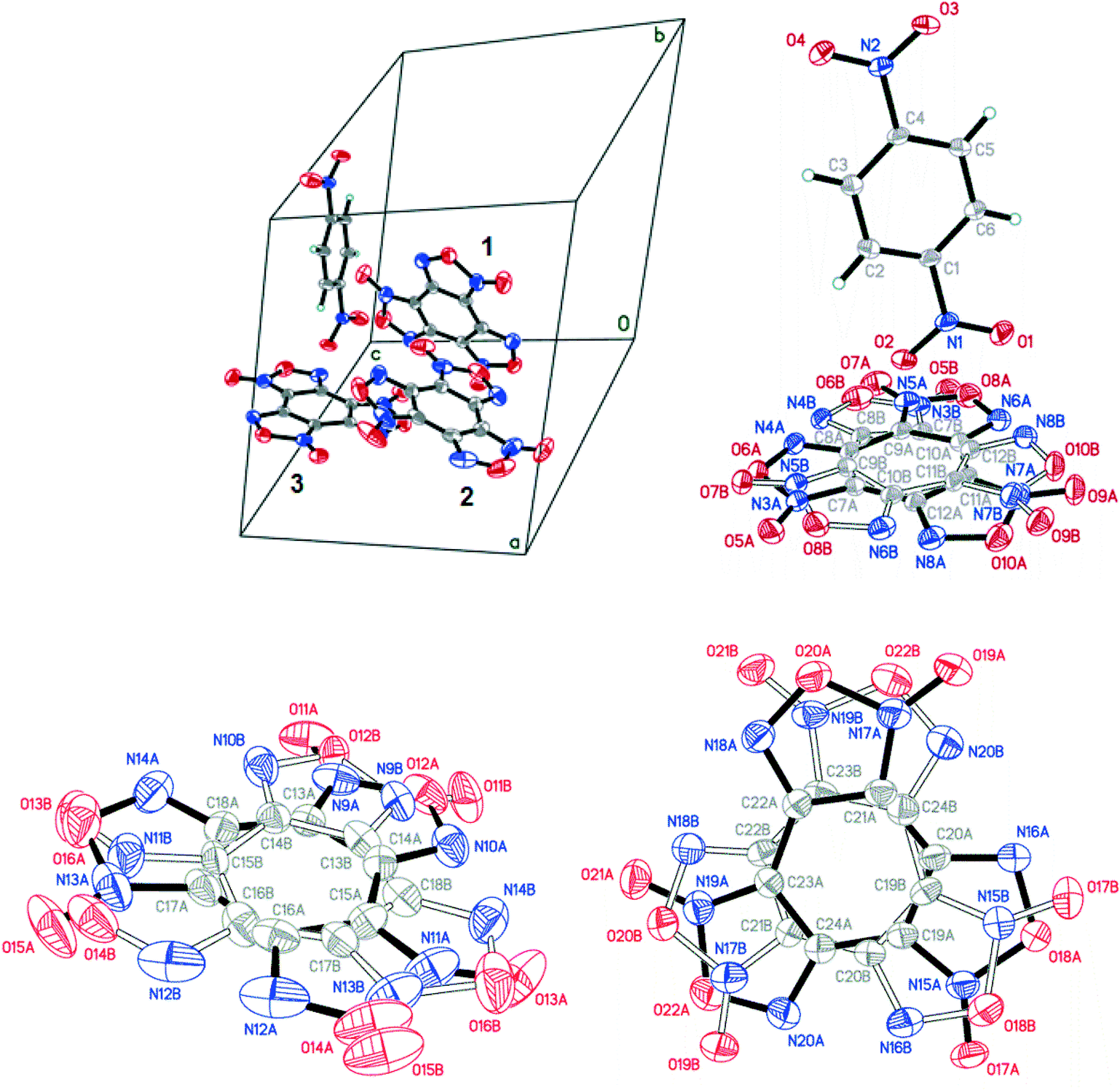 | ||
| Fig. 9 Crystal structure of BTF–1,4-DNB (3:1) cocrystal; BTF disorder is not shown (left, top). The 1,4-DNB molecule is predominantly oriented by a nitro group towards one closest BTF molecule (right, top). The A/B disorder ratios for BTF molecules are 0.9227(12):0.0773(12) for the first molecule (top, right), 0.7729(18):0.2271(18) for the second molecule (bottom, left) and 0.6750(19):0.3250(19) for the third one (bottom, right); p = 50%. | ||
The prediction of the structures of the BTF–1,4-DNB cocrystal revealed the energetic preference for the formation of the cocrystal in an unusual ratio (3:1). The structural parameters of the deepest minima, corresponding to crystal packings at other ratios of components, are presented in the ESI.† Our experimental preparation and investigation of this cocrystal by X-ray diffraction (XRD) fully confirmed the results of theoretical modeling: the predicted crystal structure is in good agreement with the experimental XRD data and has an energy of −100.46 kcal mol−1 at a molecular crystal density of 1.84 g cm−3 (Table 8). The crystal packing energy of the BTF–1,4-DNB cocrystal (3:1) indicates an energy preference of −0.91 kcal mol−1 for the formation of this cocrystal.
:1) cocrystal
| a, Å | b, Å | c, Å | α, ° | β, ° | γ, ° | ρ, g cm−3 | E, kcal mol−1 | |
|---|---|---|---|---|---|---|---|---|
| Calculated | 12.29 | 12.57 | 12.72 | 105 | 99 | 113 | 1.84 | −100.46 |
| Experimental | 12.08 | 12.36 | 12.68 | 107 | 95 | 112 | 1.88 | — |
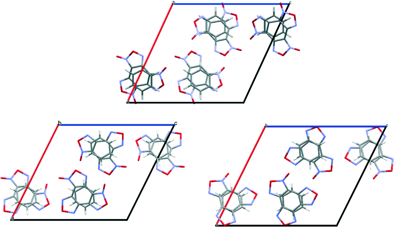
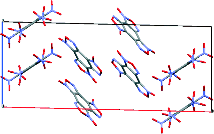
Cocrystals containing 3 BTF molecules per 1 molecule of another component were previously unknown. In the cocrystalline packing, disordering of all three independent BTF molecules is observed with the predominance of one of two possible orientations. Due to the disordering in two possible arrangements of BTF molecules in the cocrystal, we used the orientations with the highest statistical weights to compare the predicted and the experimental packing. Images of the experimental and calculated packing are shown in Fig. 10.
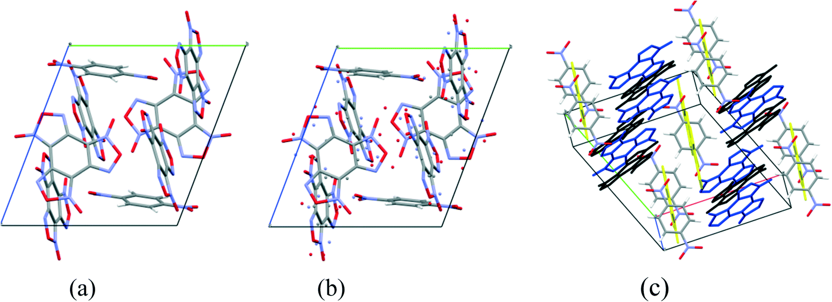 | ||
| Fig. 10 Projection from the [011] side of cocrystal packing of BTF–1,4-DNB (3:1): (a) is the simulated packing, (b) is the experimental packing, and (c) is image of the packing motif in the cocrystal (independent BTF molecules in the cocrystal are shown in black, blue and yellow). | ||
The general motif of the cocrystal packing can be divided into two layers, between which the parquet packing is observed (Fig. 10(c)). The first layer is laid flat parallel along the axis of the unit cell c and consists of alternating “blue” and “black” BTF molecules, between which π–π stacking interactions of furoxan rings are observed. The second layer is formed by successively alternating “yellow” BTF and 1,4-DNB molecules. The T-shaped complex between the “black” BTF molecule and 1,4-DNB is formed by electrostatic interactions and corresponds to a “sandwich” in which 1,4-DNB molecules are sandwiched between two black BTF molecules from above and below. Parquet packing is observed between these two layers in the cocrystal structure.
The shortest in absolute length, O⋯H and N⋯H contacts between BTF and 1,4-DNB, form pseudo-hydrogen bonds with a length of about ∼2.507–2.736 Å. The second longest atom–atom contacts are O⋯O contacts formed between oxygen atoms during π–π stacking interaction of “blue” and “black” BTF molecules. Considering not the absolute lengths of interatomic contacts but the relative lengths of the pair contact minus the sum of the van der Waals radii of each of the atoms, it can be stated that the shortest contacts are C⋯O contacts in the sandwich complex between the carbon atoms of the “black” BTF molecule and the oxygen atoms of the nitro group 1,4-DNB. The relative length of such contacts is 0.159–0.237 Å shorter than the sum of the van der Waals radii of oxygen and carbon atoms, which is associated with a strong electrostatic interaction between a negatively charged oxygen atom and a positively charged carbon atom.
The Hirshfeld surface analysis of each independent BTF 1,2,3 molecule (see Fig. 9 top left,) indicates the predominance of O⋯O, N⋯O, and C⋯O contacts. For all three molecules, the most predominant contact is N⋯O, which is obviously related to the number of BTF molecules and, accordingly, a large number of oxygen and nitrogen atoms (Fig. 11).
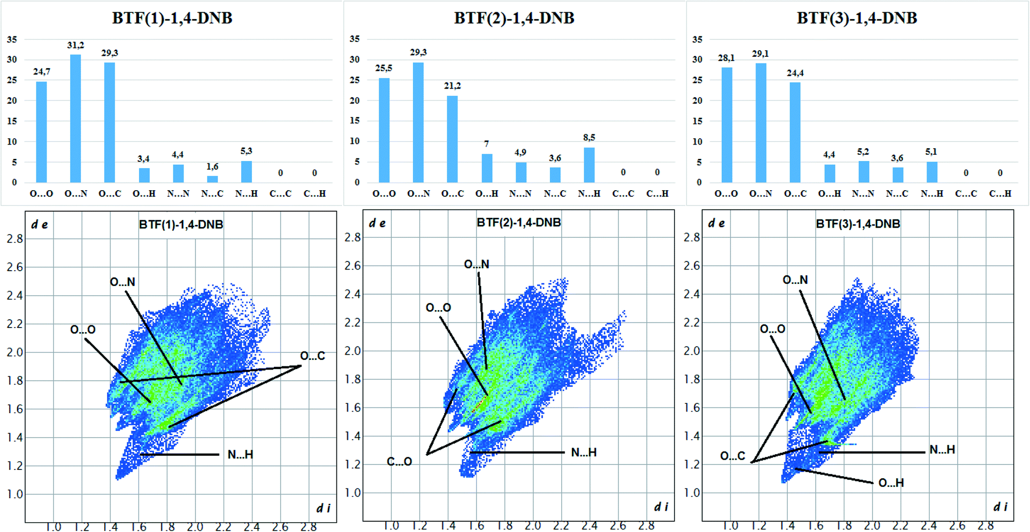 | ||
| Fig. 11 Results of 2D fingerprint plot calculation for each independent BTF molecule in cocrystal BTF–1,4-DNB (3:1). | ||
In the case of the BTF 3 molecule, the values (di and de) of the C⋯O contact on the two-dimensional map are lower than for BTF 1,2 molecules and cocrystals with nitrobenzene and 1,3-dinitrobenzene, which is associated with the formation of a T-shaped complex and the strong electrostatic interaction of nitro groups with BTF.
Thus, using the example of cocrystallization of BTF with isomeric o-, m-, and p-DNB, it can be noted that cocrystallization of components in low-polarity methylene chloride is in good agreement with the calculations, and in more polar methanol (a solvent with strong hydrogen bonds), the cocrystallization pattern changes dramatically.
:1 ratio13 is formed in the space group P21/c with a density of 1.81 g cm−3. The structure and packing motif of the BTF–TNB cocrystal are analyzed in detail.13 The experimental and calculated crystal packing corresponding to the global minimum PES are shown in Fig. 12.
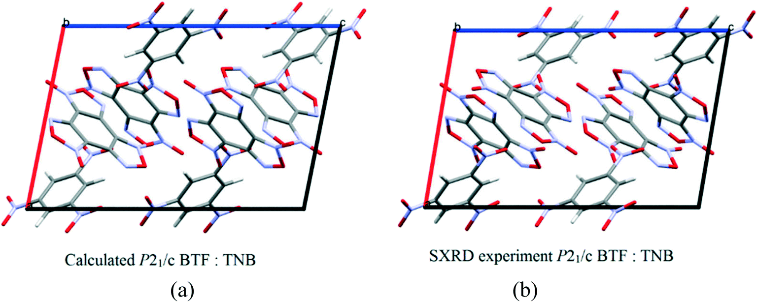 | ||
| Fig. 12 (a) Calculated cocrystal packing of BTF with TNB (1:1); (b) experimental13 packing. | ||
As can be seen from Fig. 12, the calculated cocrystal packing is in full agreement with the SXRD experiment. The global minimum of the PES of the BTF–1,3,5-TNB cocrystal (1:1) corresponds to the optimal packing with a lattice energy of −50.94 kcal mol−1 (Table 9).
:1)
| a, Å | b, Å | c, Å | α, ° | β, ° | γ, ° | ρ, g cm−3 | E, kcal mol−1 | |
|---|---|---|---|---|---|---|---|---|
| Calculated | 9.95 | 11.80 | 14.64 | 90 | 101 | 90 | 1.83 | −50.94 |
| Experimental | 9.55 | 12.57 | 14.45 | 90 | 100 | 90 | 1.81 | — |
As follows from Table 9, the differences in the unit cell parameters are minimal between the experimental and the predicted structures of BTF–1,3,5-TNB (1:1), and the negative value of the cocrystallization energy (−1.31 kcal mol−1) is in good agreement with the experimental results. Cocrystals with other ratios of coformers were not obtained, which is consistent with the prediction, since positive values of the cocrystallization energy were obtained (Table 4).
:1 ratio of components.
The prediction of the structure of the BTF–HNB cocrystal was carried out only for the 1:1 component ratio. As a result, the deepest minimum was found in the space group P21/c with the unit cell parameters a, b, c = 23.58, 8.85, 9.58 Å and α, β, γ = 90, 91, 90, with a molecular crystal density of 1.992 g cm−3 (Fig. 13).
 | ||
| Fig. 13 Calculated packing of BTF–HNB (1:1) cocrystal. | ||
It was assumed that the geometry of the BTF–HNB complex would be similar to that of the BTF–TNB and BTF–TNT complexes with p–π-stacking interactions between the NO2 groups and the BTF nucleus. In ref. 41, based on the quantum chemical calculation of the electrostatic potential, it was shown that the aromatic nucleus of HNB is depleted in electron density compared to the BTF molecule, which probably affects the predicted packing, and the nitro groups of HNB do not form a T-shaped complex with BTF molecules. The simulated crystal packing consists of complexes formed by the interaction of the N-oxide group of furoxan and the benzene ring of HNB as well as the BTF–BTF interaction, similar to those present in BTF in 1,3-DNB and 1,4-DNB.
Thus, the “accumulation” of nitro groups from nitrobenzene to HNB leads to the absence of the possibility of complexation with BTF due to the depletion of the electron density of the aromatic nucleus. Hence, hexanitrobenzene becomes more electron-withdrawing than “hexanitrosobenol” (BTF), and therefore the principle of complexation changes dramatically. In addition, there are no CH bonds in HNB that can form pseudo-hydrogen bonds with BTF.
The atom coordinates of the predicted crystal packing of the BTF–HNB complex are presented in the ESI.†
Thus, comparing the cocrystallization of mono-, di-, tri-, and hexanitrobenzenes with BTF, it can be concluded with some certainty that the cocrystallization processes are influenced not only by electron-donor/electron-withdrawing interactions and hydrogen/pseudo-hydrogen bonds.
5. Conclusions
Thus, we have modeled the structure of BTF cocrystals with benzene and high-energy compounds of the aromatic series, namely nitrobenzene, 1,2-, 1,3-, and 1,4-dinitrobenzene, 1,3,5-trinitrobenzene, and hexanitrobenzene, with different ratios of components (1:1, 1:2, 1:3 and in reverse order). Based on the estimation of the enthalpies of cocrystallization, possibilities of cocrystal formation were predicted, some of which were obtained and studied by XRD methods.
Analysis of the interactions of BTF with coformers indicates that the formation of cocrystals is due to several factors: a set of formed T-shaped complexes as well as the presence of π–π stacking interactions between the six-membered ring system of BTF and nitrobenzenes, forming a common packing motif. The strong polarizing effects of oxygen and nitrogen atoms of the BTF molecule, being a π system with a low electron content, cause interactions with coformers relatively rich in electron density due to nitro groups, which determines the formation of cocrystals.
The cocrystals BTF–benzene (1:1), BTF–nitrobenzene (1:1), BTF–1,3-dinitrobenzene (1:1) and BTF–1,4-dinitrobenzene (3:1) were obtained and studied by single-crystal X-ray diffraction. It should be noted that cocrystals with three BTF molecules and one coformer molecule per unit cell were prepared for the first time.
The effect of the solvent and an excess of one of the components on the possibility of cocrystal formation is clearly shown by experimental procedures.
Conflicts of interest
There are no conflicts to declare.Acknowledgements
The supercomputer resources were provided by ‘MVS100K’ of the Russian Academy of Sciences.References
- O. Bolton and A. J. Matzger, Angew. Chem., Int. Ed., 2011, 50, 8960–8963 CrossRef CAS.
- O. Bolton, L. R. Simke, P. F. Pagoria and A. J. Matzger, Cryst. Growth Des., 2012, 12, 4311–4314 CrossRef CAS.
- Z. Yang, H. Li, H. Huang, X. Zhou, J. Li and F. Nie, Propellants, Explos., Pyrotech., 2013, 38, 495–501 CrossRef CAS.
- K. B. Landenberger, O. Bolton and A. J. Matzger, J. Am. Chem. Soc., 2015, 137, 5074–5079 CrossRef CAS.
- J. C. Bennion, A. McBain, S. F. Son and A. J. Matzger, Cryst. Growth Des., 2015, 15, 2545–2549 CrossRef CAS.
- J. Zhang and J. M. Shreeve, CrystEngComm, 2016, 18, 6124–6133 RSC.
- Y. Tan, Z. Yang, H. Wang, H. Li, F. Nie, Y. Liu and Y. Yu, Cryst. Growth Des., 2019, 19, 4476–4482 CrossRef CAS.
- N. Liu, B. Duan, X. Lu, Q. Zhang, M. Xu, H. Mo and B. Wang, CrystEngComm, 2019, 21, 7271–7279 RSC.
- G. Liu, S. H. Wei and C. Zhang, Cryst. Growth Des., 2020, 20, 7065–7079 CrossRef CAS.
- Y. Tan, Y. Liu, H. Wang, H. Li, F. Nie and Z. Yang, Cryst. Growth Des., 2020, 20, 3826–3833 CrossRef CAS.
- A. S. Bailey and J. R. Case, Tetrahedron, 1958, 3, 113–131 CrossRef CAS.
- A. S. Bailey, R. J. P. Williams and J. D. Wright, J. Chem. Soc., 1965, 2579–2587 RSC.
- H. Zhang, C. Guo, X. Wang, J. Xu, X. He, Y. Liu, X. Liu, H. Huang and J. Sun, Cryst. Growth Des., 2013, 13, 679–687 CrossRef CAS.
- Z. Yang, H. Li, X. Zhou, C. Zhang, H. Huang, J. Li and F. Nie, Cryst. Growth Des., 2012, 12, 5155–5158 CrossRef CAS.
- V. P. Zelenov, N. M. Baraboshkin, D. V. Khakimov, N. V. Muravyev, D. B. Meerov, I. A. Troyan, T. S. Pivina, A. V. Dzyabchenko and I. V. Fedyanin, CrystEngComm, 2020, 22, 4823–4832 RSC.
- L. M. Foroughi, R. A. Wiscons, D. R. Du Bois and A. J. Matzger, Chem. Commun., 2020, 56, 2111–2114 RSC.
- C. R. Taylor and G. M. Day, Cryst. Growth Des., 2018, 18, 892–904 CrossRef CAS.
- F. Lu, Y. Dong, T. Fei, J. Liu, H. Su, S. Li and S. Pang, Cryst. Growth Des., 2019, 19, 7206–7216 CrossRef CAS.
- C. J. Chapman and L. J. Groven, J. Energ. Mater., 2021 DOI:10.1080/07370652.2020.1867936 , ahead-of-print.
- M. Pakhnova, I. Kruglov, A. Yanilkin and A. R. Oganov, Phys. Chem. Chem. Phys., 2020, 22, 16822–16830 RSC.
- M. J. Frisch, G. W. Trucks, H. B. Schlegel, G. E. Scuseria, M. A. Robb, J. R. Cheeseman, G. Scalmani, V. Barone, B. Mennucci, G. A. Petersson, H. Nakatsuji, M. Caricato, X. Li, H. P. Hratchian, A. F. Izmaylov, J. Bloino, G. Zheng, J. L. Sonnenberg, M. Hada, M. Ehara, K. Toyota, R. Fukuda, J. Hasegawa, M. Ishida, T. Nakajima, Y. Honda, O. Kitao, H. Nakai, T. Vreven, J. A. Montgomery, J. E. Peralta, F. Ogliaro, M. Bearpark, J. J. Heyd, E. Brothers, K. N. Kudin, V. N. Staroverov, T. Keith, R. Kobayashi, J. Normand, K. Raghavachari, A. Rendell, J. C. Burant, S. S. Iyengar, J. Tomasi, M. Cossi, N. Rega, J. M. Millam, M. Klene, J. E. Knox, J. B. Cross, V. Bakken, C. Adamo, J. Jaramillo, R. Gomperts, R. E. Stratmann, O. Yazyev, A. J. Austin, R. Cammi, C. Pomelli, J. W. Ochterski, R. L. Martin, K. Morokuma, V. G. Zakrzewski, G. A. Voth, P. Salvador, J. J. Dannenberg, S. Dapprich, A. D. Daniels, O. Farkas, J. B. Foresman, J. V. Ortiz, J. Cioslowski and D. J. Fox, Gaussian 09, Revision D.01, Gaussian, Inc., Wallingford CT, 2013 Search PubMed.
- G. M. Day, W. D. S. Motherwell and W. Jones, Cryst. Growth Des., 2005, 5, 1023–1033 CrossRef CAS.
- A. V. Dzyabchenko, Russ. J. Phys. Chem. A, 2008, 82, 758–766 CrossRef CAS.
- A. J. Pertsin and A. I. Kitaigorodsky, J. Comput. Chem., 1987, 2, 69–148 Search PubMed.
- D. V. Khakimov, A. V. Dzyabchenko and T. S. Pivina, Propellants, Explos., Pyrotech., 2019, 1–8 CAS.
- D. S. Coombes, Philos. Mag. B, 1996, 73, 117–125 CrossRef CAS.
- A. V. Dzyabchenko, Russ. J. Phys. Chem. A, 2008, 82, 1663–1671 CrossRef CAS.
- V. K. Belsky, O. N. Zorkaya and P. M. Zorky, Acta Crystallogr., Sect. A: Found. Crystallogr., 1995, 51, 473–481 CrossRef.
- A. J. Cruz Cabeza, E. Pidcock, G. M. Day, W. D. S. Motherwell and W. Jones, CrystEngComm, 2007, 9, 556 RSC.
- A. V. Dzyabchenko, Acta Crystallogr., Sect. B: Struct. Sci., 1994, 50, 414–425 CrossRef.
- P. R. Spackman, M. J. Turner, J. J. McKinnon, S. K. Wolff, D. J. Grimwood, D. Jayatilaka and M. A. Spackman, J. Appl. Crystallogr., 2021, 54, 1006–1011 CrossRef CAS PubMed.
- Z. Yang, Y. Wang, J. Zhou, H. Li, H. Huang and F. Nie, Propellants, Explos., Pyrotech., 2014, 39, 9–13 CrossRef CAS.
- D. Becker, JANNAF Combustion Meeting (26th). Volume 2. Held in Pasadena, California on 23–27 October 1989, 1989 Search PubMed.
- L. Krause, R. Herbst-Irmer, G. M. Sheldrick and D. Stalke, J. Appl. Crystallogr., 2015, 48, 3–10 CrossRef CAS.
- G. M. Sheldrick, Acta Crystallogr., Sect. A: Found. Adv., 2015, 71, 3–8 CrossRef.
- G. M. Sheldrick, Acta Crystallogr., Sect. C: Struct. Chem., 2015, 71, 3–8 Search PubMed.
- Z. A. Akopyan, Y. T. Struchkov and V. G. Dashevskii, J. Struct. Chem., 1966, 7, 385–392 CrossRef.
- N. V. Muravyev, K. A. Monogarov, I. N. Melnikov, A. N. Pivkina and V. G. Kiselev, Phys. Chem. Chem. Phys., 2021, 23, 15522–15542 RSC.
- J. C. A. Boeyens and F. H. Herbstein, J. Phys. Chem., 1965, 69, 2153–2159 CrossRef CAS.
- S. Tsuzuki, K. Honda, T. Uchimaru and M. Mikami, J. Chem. Phys., 2006, 125, 124304 CrossRef PubMed.
- C. Zhang, X. Xue, Y. Cao, J. Zhou, A. Zhang, H. Li, Y. Zhou, R. Xu and T. Gao, CrystEngComm, 2014, 16, 5905–5916 RSC.
Footnote |
| † Electronic supplementary information (ESI) available. CCDC 2095321–2095323. For ESI and crystallographic data in CIF or other electronic format see DOI: 10.1039/d1ce00977j |
| This journal is © The Royal Society of Chemistry 2022 |