DOI:
10.1039/D2CC01709A
(Communication)
Chem. Commun., 2022,
58, 10675-10678
Electrochemical performances of a LiFePO4-based heat-treated activated carbon electrode†
Received
16th April 2022
, Accepted 15th August 2022
First published on 5th September 2022
Abstract
Activated carbon was heat-treated to investigate the effect of heat-treating activated carbon on the power and long-term reliability characteristics of LiFePO4-based electrodes. As the heat-treatment temperature of the activated carbon increased, the surface area and total pore volume were decreased. In addition, oxygen functional groups were decomposed and the O/C ratio on the pore surface was reduced. The power and long-term reliability characteristics of the composite electrodes were improved by the use of heat-treated activated carbon, which probably resulted from an increase in the electrical conductivity of the electrodes as the bulk resistance and surface resistance of the heat-treated activated carbon decreased. The diffusion coefficient of the LFP/AC electrode was considerably increased due to the pores of activated carbon.
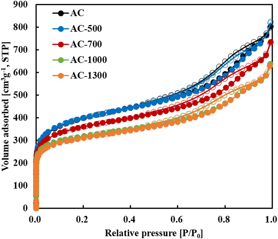
With the development of materials and cell assembly technology, the application range of energy storage devices has gradually expanded from home appliances and mobile communication devices to electric vehicles and energy storage systems (ESSs). Lithium-ion batteries (LIBs) and electric double-layer capacitors (EDLCs) are widely used in energy storage devices.1 LIBs have the advantage of storing a large amount of energy through an oxidation-reduction reaction, but have the disadvantages of poor power and long-term reliability. In contrast, EDLCs have excellent power and long-term reliability as a result of the physical adsorption–desorption mechanism with electrolyte ions on the surface of activated carbon but have low energy density.2 Generally, LIB and EDLC energy storage devices with opposite characteristics are used in parallel inside systems or cells to compensate for the disadvantages while complimenting the advantages. Energy storage devices that connect them in parallel inside a cell and use a Li-ion electrolyte can be broadly classified as a lithium-ion capacitor (LIC).3 In a typical LIC, an activated carbon electrode and a Li-lithiated electrode are used as the cathode and anode, respectively, exhibiting superior electrochemical characteristics in terms of operation voltage and energy density (3.8 V, 11–30 W h kg−1), compared to EDLCs. This LIC is used by some companies as a backup power source for automotive electronics or as a communication power source for auto meter readers (AMRs).4 LICs with electrodes that combine lithium metal oxide for LIBs and activated carbon for EDLCs are being studied to improve LIB-based power and long-term reliability characteristics.5 Bockenfeld et al. reported that the addition of activated carbon to a LiFePO4 electrode improved its rate capability.6,7 They attributed this to the relatively higher electrical conductivity of activated carbon and the dilution of LiFePO4 by activated carbon inside the electrode, which prevented the aggregation of the LiFePO4 particles. From a structural perspective, Wang et al. reported that the addition of activated carbon increased the specific surface area of LiFePO4 composite electrodes, thereby increasing the power.8 According to Peng et al., the larger the specific surface area of the activated carbon added, the better the rate capability of LiFePO4.9 In these studies, the power of the composite electrodes was improved because the activated carbon pores present around the LiFePO4 particles served as storage for the electrolyte or improved tortuosity in the electrode, allowing the smooth supply of Li ions to LiFePO4. Most of the aforementioned studies discuss the transport properties of Li ions through activated carbon pores, but few have reported on the effect of the electrical conductivity of activated carbon on the power characteristics of composite electrodes. The electrical conductivity of activated carbon is significantly influenced by the crystal structure of the raw material, the pore structure formed during the activation process, and the acidic functional groups on the surface. In this study, activated carbon was heat-treated at various temperatures to examine changes in the specific surface area, pore structure, and acidic functional groups to improve its electrical conductivity. In addition, the electrochemical characteristics, such as capacity, resistance, and rate capability of LiFePO4-activated carbon electrodes were investigated. Fig. 1 shows the N2 adsorption–desorption isotherms of each activated carbon. In the figure, each activated carbon exhibited a typical type IV isotherm with a hysteresis loop, and a decrease in gas adsorption was observed in the low relative pressure region as the heat-treatment temperature increased. This indicates that during heat-treatment at a high temperature, the micropore volume (Vmicro) of the activated carbon was reduced by the shrinkage or blocking of micropores.10 Moreover, as the heat-treatment temperature of the activated carbon increased, the hysteresis loop moved toward a lower pressure because the volume of mesopores decreased. Besides, a relatively smooth surface was obtained as the heat-treatment temperature increased (Fig. S1, ESI†). The rough surface of the activated carbon may be attributed to the effect of the pores formed near the surface during the H3PO4-activation process, causing indentations on the surface, or to fine particles caused by partial fragmentation of the surface. On the contrary, the smooth surface at high heat-treatment temperatures is believed to be the result of the removal of fine particles by carbonization during heat-treatment. However, as the D50 of the heat-treated activated carbon at each temperature was 6–7 μm, the heat-treatment temperature had no effect on the particle size. Table S1 (ESI†) shows the BET surface area (SBET), total pore volume (Vtot), and pore volume by pore size obtained from the N2 adsorption–desorption isotherms. The micropore volume (Vmicro) and mesopore volume (Vmeso) of AC at 0.396 cm3 g−1 and 0.835 cm3 g−1, respectively, indicate that AC has a pore structure with predominantly developed mesopores. SBET and Vtot gradually decreased with increasing heat-treatment temperature, while SBET and Vtot of AC-1300 were 21% lower than those of AC. On the contrary, similar Vmicro/Vtot values regardless of the heat-treatment temperature demonstrated that the volume of each pore decreased with increasing heat-treatment temperature, but the pore size distribution hardly changed. Fig. 2 shows the XPS C 1s and O 1s spectra to examine the acidic functional groups present on the surface of the activated carbon and the heat-treated activated carbon. Fig. 2(a and b) show the XPS O 1s spectra of AC and AC-1000, where an O![[double bond, length as m-dash]](https://www.rsc.org/images/entities/char_e001.gif) C peak at 531 eV, an O–C peak at 532 eV, and an O–C = O peak at 533 eV were observed.11Fig. 2(c) shows the atomic ratio (%) and O/C ratio (%) from the C 1s and O 1s of each activated carbon and the O/C ratio obtained from these spectra decreased as the heat-treatment temperature increased. Fig. 2(d) shows the electrode density (g/cc) and active material resistance (Ω cm) of the LFP and composite electrodes. The electrode density of the LFP/AC electrode decreased compared to that of the LFP electrode, but that of the composite electrodes gradually increased as the heat-treatment temperature increased. This is owing to changes in the bulk density of the activated carbon enhanced by the reduction in pore volume at a higher heat-treatment temperature. On the contrary, the active material resistance decreased with increasing heat-treatment temperature of the activated carbon. The LFP/AC-1300 electrode with an active material resistance of 1.1 Ωm exhibited electrical conductivity twice as high as that of the LFP/AC electrode. Therefore, the improvement in the electrical conductivity of the composite electrodes containing the heat-treated activated carbon is correlated to the change in the internal and external structures and the removal of impurities of the activated carbon. That is, the improvement in the electrical conductivity of the composite electrodes can be explained by reduction in the contact resistance by the removal of fine particles on the surface of the activated carbon particles, reduction in bulk resistance by the reduced pore volume, and reduction in surface resistance by the reduced acidic functional groups. Fig. 3(a) illustrates the voltage profiles from the charge–discharge of the LFP electrode and composite electrodes with a current of 0.2 C. While the LFP electrode exhibited a plateau region between 3.4 V and 3.5 V, the composite electrodes exhibited the plateau region of the LFP electrode as well as a voltage slope region owing to the electric double layer behavior of the activated carbon. In the case of LFP/AC, the gravimetric capacity per weight of LFP obtained based on the discharge was approximately 160 mA h g−1, and the gravimetric capacitance per weight of the activated carbon obtained from the voltage slope was approximately 108.2 F g−1.12 These values are similar to those reported in previous studies, indicating that LFP and activated carbon are connected in parallel within the electrodes without any loss of capacity caused by mutual interference. Fig. 3(b) shows the polarization determined from the difference in the SOC 50 and DOC 50 voltages of each electrode. Compared to the 119 mV of the LFP electrode, the polarization of the composite electrodes containing activated carbon decreased with increasing heat-treatment temperature. Fig. 3(c and d) show the changes in capacity retention (%) depending on the C-rate of discharge of the LFP and composite electrodes
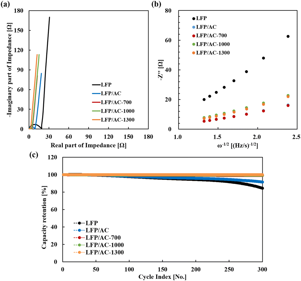
and the changes in gravimetric specific capacity of the active materials measured at each C-rate of discharge of the composite electrodes. As shown in Fig. 3(c), the LFP electrode shows a drastic drop in power from 3 C, and the capacity was minimal after 5 C. Meanwhile, the composite electrodes achieved a relatively high capacity retention, and LFP/AC-1300 demonstrated the highest capacity retention of 58% at 10 C. Fig. 3(d) shows the specific capacitance of the activated carbon and the specific capacity of the LFP for the composite electrodes. The activated carbon-specific capacitances of LFP/AC, LFP/AC-700, LFP/AC-1000, and LFP/AC-1300 at 0.2 C were 108.2, 107.3, 95.4, and 66.7 F g−1, respectively. The specific capacitance of the activated carbon decreased with increasing heat-treatment temperature because the specific surface area decreased, as shown in Table S1 (ESI†). The electric double-layer capacitance is a result of the physical adsorption/desorption at the surface, and it is difficult to observe changes in specific capacitance even at 10 C because of the high power output of the electric double-layer behavior. However, the specific capacities of LFP exhibit similar trends, as shown in Fig. 3(c). These results imply that the power characteristics of the composite electrodes are driven by LFP, and the higher power of the composite electrodes compared to that of the LFP electrode is attributed to the activated carbon. Based on the voltage behaviors and capacity that are clearly distinguishable between LFP and the activated carbon in the charge–discharge voltage profiles, a reduction in capacity owing to interference between ions or the synergy effect, as reported in previous studies, is not observed between the redox reaction of LFP and the electric double-layer behavior.8 Therefore, it is considered that the improvement in the power characteristics of the LFP particles in the composite electrodes depends on the pore structure and the surface condition of the activated carbon particles nearby, and LFP achieves higher power as it contacts the activated carbon with improved bulk resistance and surface resistance by heat-treatment, which facilitates the supply of electrons. The AC impedance was measured to analyze the resistance components of the composite electrodes in detail. Fig. 4(a) shows a Nyquist plot of the LFP electrode and composite electrodes measured at 4.2 V. The intersection on the X-axis in the high-frequency region is the electrolyte resistance (Rs), the semi-circle in the high-middle frequency region is the charge transfer resistance (Rct), and the following straight line is the Warburg resistance related to the diffusion of lithium ions.13 The semi-circle was drastically reduced by adding activated carbon to the LFP and decreased as the heat-treatment temperature of the activated carbon increased. This implies that the electrical conductivity of the electrodes is improved by the activated carbon, and the bonding of electrons and ions occurs actively because of the smooth current supply at the interface between the LFP and the electrolyte. Fig. 4(b) shows the relationship between −Z′′ and ω−1/2 in the low-frequency region, and DLi was determined using the corresponding slopes and the following equation.:14
C peak at 531 eV, an O–C peak at 532 eV, and an O–C = O peak at 533 eV were observed.11Fig. 2(c) shows the atomic ratio (%) and O/C ratio (%) from the C 1s and O 1s of each activated carbon and the O/C ratio obtained from these spectra decreased as the heat-treatment temperature increased. Fig. 2(d) shows the electrode density (g/cc) and active material resistance (Ω cm) of the LFP and composite electrodes. The electrode density of the LFP/AC electrode decreased compared to that of the LFP electrode, but that of the composite electrodes gradually increased as the heat-treatment temperature increased. This is owing to changes in the bulk density of the activated carbon enhanced by the reduction in pore volume at a higher heat-treatment temperature. On the contrary, the active material resistance decreased with increasing heat-treatment temperature of the activated carbon. The LFP/AC-1300 electrode with an active material resistance of 1.1 Ωm exhibited electrical conductivity twice as high as that of the LFP/AC electrode. Therefore, the improvement in the electrical conductivity of the composite electrodes containing the heat-treated activated carbon is correlated to the change in the internal and external structures and the removal of impurities of the activated carbon. That is, the improvement in the electrical conductivity of the composite electrodes can be explained by reduction in the contact resistance by the removal of fine particles on the surface of the activated carbon particles, reduction in bulk resistance by the reduced pore volume, and reduction in surface resistance by the reduced acidic functional groups. Fig. 3(a) illustrates the voltage profiles from the charge–discharge of the LFP electrode and composite electrodes with a current of 0.2 C. While the LFP electrode exhibited a plateau region between 3.4 V and 3.5 V, the composite electrodes exhibited the plateau region of the LFP electrode as well as a voltage slope region owing to the electric double layer behavior of the activated carbon. In the case of LFP/AC, the gravimetric capacity per weight of LFP obtained based on the discharge was approximately 160 mA h g−1, and the gravimetric capacitance per weight of the activated carbon obtained from the voltage slope was approximately 108.2 F g−1.12 These values are similar to those reported in previous studies, indicating that LFP and activated carbon are connected in parallel within the electrodes without any loss of capacity caused by mutual interference. Fig. 3(b) shows the polarization determined from the difference in the SOC 50 and DOC 50 voltages of each electrode. Compared to the 119 mV of the LFP electrode, the polarization of the composite electrodes containing activated carbon decreased with increasing heat-treatment temperature. Fig. 3(c and d) show the changes in capacity retention (%) depending on the C-rate of discharge of the LFP and composite electrodes
and the changes in gravimetric specific capacity of the active materials measured at each C-rate of discharge of the composite electrodes. As shown in Fig. 3(c), the LFP electrode shows a drastic drop in power from 3 C, and the capacity was minimal after 5 C. Meanwhile, the composite electrodes achieved a relatively high capacity retention, and LFP/AC-1300 demonstrated the highest capacity retention of 58% at 10 C. Fig. 3(d) shows the specific capacitance of the activated carbon and the specific capacity of the LFP for the composite electrodes. The activated carbon-specific capacitances of LFP/AC, LFP/AC-700, LFP/AC-1000, and LFP/AC-1300 at 0.2 C were 108.2, 107.3, 95.4, and 66.7 F g−1, respectively. The specific capacitance of the activated carbon decreased with increasing heat-treatment temperature because the specific surface area decreased, as shown in Table S1 (ESI†). The electric double-layer capacitance is a result of the physical adsorption/desorption at the surface, and it is difficult to observe changes in specific capacitance even at 10 C because of the high power output of the electric double-layer behavior. However, the specific capacities of LFP exhibit similar trends, as shown in Fig. 3(c). These results imply that the power characteristics of the composite electrodes are driven by LFP, and the higher power of the composite electrodes compared to that of the LFP electrode is attributed to the activated carbon. Based on the voltage behaviors and capacity that are clearly distinguishable between LFP and the activated carbon in the charge–discharge voltage profiles, a reduction in capacity owing to interference between ions or the synergy effect, as reported in previous studies, is not observed between the redox reaction of LFP and the electric double-layer behavior.8 Therefore, it is considered that the improvement in the power characteristics of the LFP particles in the composite electrodes depends on the pore structure and the surface condition of the activated carbon particles nearby, and LFP achieves higher power as it contacts the activated carbon with improved bulk resistance and surface resistance by heat-treatment, which facilitates the supply of electrons. The AC impedance was measured to analyze the resistance components of the composite electrodes in detail. Fig. 4(a) shows a Nyquist plot of the LFP electrode and composite electrodes measured at 4.2 V. The intersection on the X-axis in the high-frequency region is the electrolyte resistance (Rs), the semi-circle in the high-middle frequency region is the charge transfer resistance (Rct), and the following straight line is the Warburg resistance related to the diffusion of lithium ions.13 The semi-circle was drastically reduced by adding activated carbon to the LFP and decreased as the heat-treatment temperature of the activated carbon increased. This implies that the electrical conductivity of the electrodes is improved by the activated carbon, and the bonding of electrons and ions occurs actively because of the smooth current supply at the interface between the LFP and the electrolyte. Fig. 4(b) shows the relationship between −Z′′ and ω−1/2 in the low-frequency region, and DLi was determined using the corresponding slopes and the following equation.:14
where DLi represents the Li-ion diffusion coefficient (cm2 s−1), R represents the gas constant (8.314 Jmol−1 K−1), T represents the absolute temperature (K), A represents the electrode area (cm2), n represents the number of electrons involved in the redox process (1 in our case), C represents the shuttle concentration (7.69 × 10⁻³ mol cm−3), F represents the Faraday constant (96![[thin space (1/6-em)]](https://www.rsc.org/images/entities/char_2009.gif) 486 C mol−1), and σ represents the Warburg factor (Ωs−1/2), which is obtained from the following equation:
486 C mol−1), and σ represents the Warburg factor (Ωs−1/2), which is obtained from the following equation:
 |
| | Fig. 1 Nitrogen adsorption–desorption isotherms of AC, AC-500, AC-700, AC-1000 and AC-1300. | |
 |
| | Fig. 2 XPS O 1s spectra of (a) AC and (b) AC-1000. (c) Atomic percentages and O/C ratio of AC and heat treated ACs. (d) Active material resistances and electrode densities of the LFP electrode and composite electrodes. | |
 |
| | Fig. 3 (a) Charge–discharge profiles of the LFP electrode and composite electrodes. (b) Polarization between the charge and discharge plateaus. (c) Capacity retentions for the LFP electrode and composite electrodes at different discharge currents. (d) Gravimetric specific capacitances (F g−1) of AC and gravimetric specific capacities (mA h g−1) of LFP for the LFP electrode and composite electrodes. | |
 |
| | Fig. 4 (a) Nyquist plots of the LFP electrode and composite electrodes at the full charge state. (b) The relationship between −Z′′ and ω−1/2 at low frequency. (c) Cycling stabilities of the LFP electrode and composite electrodes. | |
The Warburg factor of the LFP, LFP/AC, LFP/AC-700, LFP/AC-1000, and LFP/AC-1300 electrodes was 39.9, 9.9, 10.3, 13.8, and 14.0 Ωs−1/2, respectively, and the corresponding lithium ion diffusion coefficient was 9.7 × 10⁻¹⁵, 15.7 × 10⁻¹⁴, 13.7 × 10⁻¹⁴, 8.0 × 10⁻¹⁴, and 7.9 × 10⁻¹⁴ cm2 s−1, respectively. The diffusion coefficient of the LFP/AC electrode was significantly higher than that of the LFP electrode, but that of the composite electrodes with heat-treated activated carbon was reduced. This implies that the diffusion of lithium ions is greatly improved by the pores of the activated carbon, but is reduced to some extent by the change in the pore volume of the activated carbon. Despite this result, the power characteristics are superior at higher heat-treatment temperatures, as shown in Fig. 3(c), because the improved electrical conductivity of the activated carbon has a more significant effect on the power characteristics of the LFP. As shown in the results of previous studies, the general purpose of adding activated carbon to lithium metal oxide electrodes is to improve the compatibility of the electrodes with the electrolyte based on the dilution effect of the electrodes. However, unless the reduction in pore volume significantly affects the diffusion characteristics of lithium ions, the improvement of electrical conductivity by the reduction in the bulk resistance and surface resistance of activated carbon is essential for enhancing the power characteristics and long-term reliability of composite electrodes. Fig. 4(c) shows the changes in capacity retention depending on the charge–discharge cycles of the LFP and composite electrodes. The LFP electrode degraded rapidly at approximately 250 cycles, whereas there were no noticeable changes in the capacity retention of the composite electrodes containing the activated carbon heat-treated above 1000 °C for up to 300 cycles. The LFP electrode degraded at a high C-rate because the non-uniform current and ions transferred to the surface deform the internal structure of the LFP. The addition of activated carbon improved the electrical conductivity of the electrodes to facilitate the supply of current and ions to the LFP, but metal residues occurring during the activation process of the activated carbon, acidic functional groups on the surface of the pores, and the adsorbed water remaining in the micropores degraded the long-term reliability of the composite electrodes. The degradation of the LFP/AC electrode is assumed to be the result of byproducts or the gas produced from the reaction between these impurities and the electrolyte, blocking pores, or acting as an insulating layer. On the contrary, the long-term reliability of the composite electrodes containing the heat-treated activated carbon was improved, likely because most impurities were removed during the heat-treatment at 1000 °C or higher. Therefore, the addition of activated carbon to the lithium metal oxide simultaneously improves the electrical conductivity of the composite electrodes and the diffusion characteristics of ions, but it is important to minimize the effects of the acidic functional groups and the adsorbed water on the surface of the activated carbon to improve the long-term reliability. In summary, as the heat-treatment temperature of the activated carbon increased, the total pore volume (Vtot) and O/C ratio on the pore surface decreased. The power characteristics of the composite electrodes were improved by the increased bulk density of the activated carbon around the LFP. Additionally, the higher the heat-treatment temperature of the activated carbon, the better the long-term reliability of the composite electrodes. Therefore, the power characteristics of the composite electrodes containing the heat-treated activated carbon were improved, presumably because the electrical conductivity of the electrodes increased by the reduction in the bulk resistance and surface resistance of the activated carbon. In particular, the improvement in the long-term reliability of the composite electrodes was attributed to the removal of acidic functional groups on the surface of the activated carbon or the adsorbed water present in the pores.
Conflicts of interest
There are no conflicts of interest to declare.
Notes and references
- H. L. Ferreira, R. Garde, G. Fulli, W. Kling and J. P. Lopes, Energy, 2013, 53, 288–298 CrossRef.
- Y. Liu, B. Yang, X. Dong, Y. Wang and Y. Xia, Angew. Chem., 2017, 56, 16606–16610 CrossRef CAS PubMed.
- W. Cao, Y. Li, B. Fitch, J. Shih, T. Doung and J. Zheng, Chem. Eng. Sci., 2019, 200, 80–86 CrossRef.
- W. J. Cao, M. Greenleaf, Y. X. Li, D. Adams, M. Hagen, T. Doung and J. P. Zheng, J. Power Sources, 2015, 280, 600–605 CrossRef CAS.
- Y. Guan, J. Shen, X. Wei, Q. Zhu, X. Zheng, S. Zhou and B. Xu, Electrochim. Acta, 2019, 294, 148–155 CrossRef CAS.
- N. Böckenfeld, R.-S. Kuhnel, S. Passerini, M. Winter and A. Balducci, J. Power Sources, 2011, 196, 4136–4142 CrossRef.
- N. Böckenfeld, T. Placke, M. Winter, S. Passerini and A. Balducci, Electrochim. Acta, 2012, 76, 130–136 CrossRef.
- B. Wang, Q. Wang, B. Xu, T. Liu, D. Wang and G. Zhao, RSC Adv., 2013, 3, 20024–20033 RSC.
- J. Peng, J. Yu, B. Meng, L. Wang, X. Zhang, W. Cheng, P. Wen, J. Zhao, L. Li and Z. Fang, Mater. Express, 2020, 10, 523–530 CrossRef CAS.
- S. Shiraishi, Boletín GEC, 2013, 28, 18–24 Search PubMed.
- S. Reiche, R. Blume, X. C. Zhao, D. Su, E. Kunkes, M. Behrens and R. Schlogl, Carbon, 2014, 77, 175–183 CrossRef CAS.
- G. G. Amatucci, F. Badway, A. D. Pasquier and T. Zheng, J. Electrochem. Soc., 2001, 148, A930 CrossRef CAS.
- X. Tu, Y. Zhou, Z. Tian, Y. Song, C. Deng and H. Zhu, Electrochim. Acta, 2016, 222, 64–73 CrossRef CAS.
- J.-Y. Shih, G.-Y. Lin, Y.-J. J. Li, T.-F. Hung, R. Jose, C. Karuppiah and C.-C. Yang, Electrochim. Acta, 2022, 419, 140356 CrossRef CAS.
|
| This journal is © The Royal Society of Chemistry 2022 |
Click here to see how this site uses Cookies. View our privacy policy here. 
 Open Access Article
 This Open Access Article is licensed under a Creative Commons Attribution-Non Commercial 3.0 Unported Licence
 ab,
Sunhye
Yang
a,
Jongkyu
Back
ac,
Seungwook
Eom
a and
Ick-Jun
Kim
*a
ab,
Sunhye
Yang
a,
Jongkyu
Back
ac,
Seungwook
Eom
a and
Ick-Jun
Kim
*a