
 Open Access Article
 This Open Access Article is licensed under a
 Creative Commons Attribution 3.0 Unported Licence
Control of supramolecular organizations by coordination bonding in tetrapyridylporphyrin thin films†
Kazutaka
Tomita
,
Nobutaka
Shioya
,
Takafumi
Shimoaka
 ,
Masayuki
Wakioka
and
Takeshi
Hasegawa
*
,
Masayuki
Wakioka
and
Takeshi
Hasegawa
*
Institute for Chemical Research, Kyoto University, Gokasho, Uji, Kyoto 611–0011, Japan. E-mail: htakeshi@scl.kyoto-u.ac.jp
First published on 18th January 2022
Abstract
Coordination bonding has been employed for the first time to control molecular orientation in thin films and is demonstrated by using tetrapyridylporphyrin. Changing the central metal ion of porphyrin controls the balance of the coordination bonding and hydrogen bonding, and edge-on orientation has been realized for the first time as well as face-on orientation. The mechanism of the film structure formation is comprehensively explained based on the electron configuration of the central metal ion.
The molecular orientation of organic semiconductors is closely related to the performance of thin-film-based electronic devices. For example, if the conjugated rings are packed with standing (edge-on) orientation to the substrate, charge carriers are easily transported parallel to the substrate, making it suitable for the active layer of devices such as organic field-effect transistors (OFETs).1–9 Noh and co-workers reported that the edge-on and lying (face-on) orientations of platinum(II) octaethylporphyrin change the carrier mobility in OFETs: the edge-on case exhibits a ∼100 times higher mobility than the face-on one.1 Therefore, control of the molecular orientation of the semiconductor material on dielectric layers such as silicon oxide is vital to optimize device performance.
When the semiconductor materials are deposited on the dielectric layer, the anisotropic intermolecular interactions naturally induce the resulting molecular orientation during the molecular aggregation process. For example, a planar conjugated compound represented by phthalocyanine generates multilayers of the molecules, in which the intermolecular interaction in the ring-stacking direction is stronger than that in the interlayer direction.10,11 In this case, the relatively strong ring-stacking interaction is aligned parallel to the substrate surface, so that the surface energy of the resulting layer would be reduced. In other words, the standing (edge-on) orientation gives the thermodynamically stable structure on silicon in this case.12
On the other hand, some planar compounds with hydrogen-bonding yielding groups such as 1,4,5,8-naphthalenetetracarboxylic and 3,4,9,10-perylenetetracarboxylic diimides are known to take the face-on orientation.13–16 In these films, the hydrogen bonding forms a two-dimensional (2D) supramolecular structure along the substrate, in which the planar molecules are aligned parallel to the 2D aggregate. Yokoyama and co-workers demonstrated that several amorphous materials containing pyridine rings exhibited face-on orientation due to intermolecular hydrogen bonding.17,18 Using a similar approach, a star-shaped phthalimide-based molecule has recently been designed by Nakamura et al.19 This compound has three N–H/O hydrogen bonding sites forming a 2D supramolecular structure, yielding face-on orientation. Therefore, molecular design considering anisotropic intermolecular interactions is an important chemical strategy for controlling molecular orientation.
The molecular design strategy using intermolecular hydrogen bonding, in this manner, works to realize the face-on orientation of target molecules, but the strategy does not work for the edge-on one. Here, we propose another chemical strategy using intermolecular “coordination bonds” to realize the edge-on orientation. In this study, a series of metallated tetrapyridylporphyrins (MTPyPs, M = metal; Fig. 1a) with four pyridyl rings on the porphyrin skeleton is investigated. If Fe(II) is chosen for the central metal ion of the porphyrin ring, the compound, FeTPyP, is reported to generate a molecular aggregate, in which the molecules are aligned by the intermolecular coordination bonds between the pyridine ring and the metal ion in a single-crystal structure.20 Since each coordination bond is “perpendicular” to the porphyrin ring, the molecules should have the edge-on orientation in the polycrystalline thin film as illustrated in Fig. 1b. However, this supramolecular structure has not been used for molecular orientation control in “thin films” thus far. To investigate the influence of the central metal ion on the molecular orientation, in the present study, a series of MTPyPs, containing Fe(II), Co(II), Ni(II), and Cu(II) ions, is studied. These compounds were synthesized by referring to the literature.21 The supramolecular organization in the vapor-deposited MTPyP film was investigated by using the two-dimensional grazing incidence X-ray diffraction (2D-GIXD) and infrared p-polarized multiple-angle incidence resolution spectrometry (IR pMAIRS)22 techniques (detailed experimental conditions are in the ESI†).
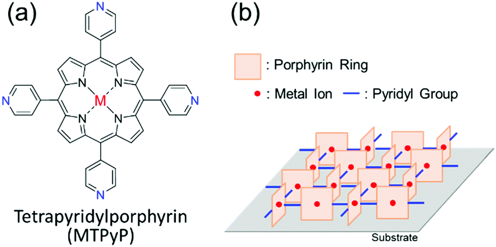 | ||
| Fig. 1 (a) Molecular structure of MTPyP. (b) Expected supramolecular structures formed by metal/N coordination bonds.20 The pyridyl groups that are not used for the coordination bonds were omitted. | ||
To reveal the molecular aggregation structure depending on the central metal ion of MTPyPs, we first discuss the 2D-GIXD pattern of the FeTPyP film (Fig. 2a). This pattern exhibits several spot-like reflections, which indicates that the molecules are highly organized. By referring to the lattice parameters of the single-crystal structure20 (CCDC No. 179299; denoted “form I”), the reflection on the qz axis (q = 6.9 nm−1) is derived from the (200) plane of the form I crystal, which suggests the formation of intermolecular coordination bonding. Since the (200) plane parallel to the film surface is perpendicular to the porphyrin plane (Fig. 3a), the compound is thus determined to have the edge-on orientation as expected. Comparison with the simulated pattern of the (200) plane oriented parallel to the substrate (Fig. S1a, ESI†) reveals that the rest of the reflection spots in Fig. 2a are all consistent with the edge-on orientation of the form I crystallite.
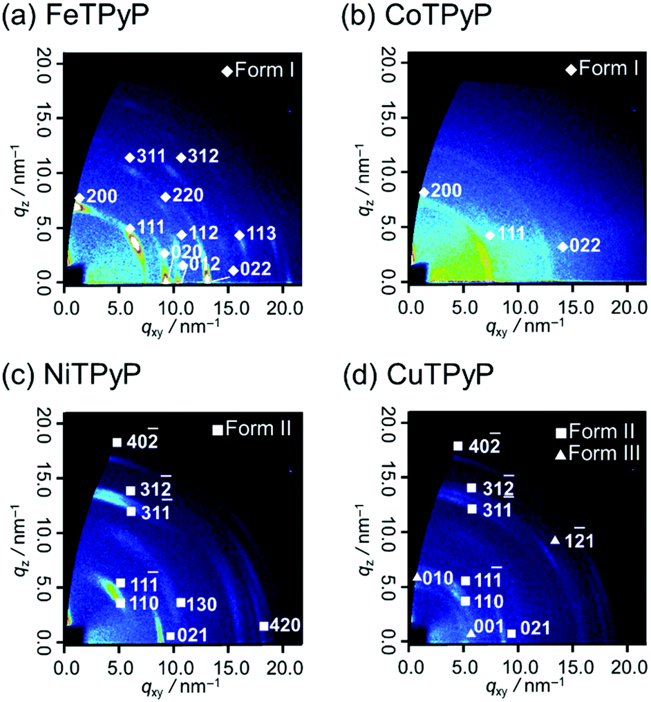 | ||
| Fig. 2 2D-GIXD patterns of (a) FeTPyP, (b) CoTPyP, (c) NiTPyP, and (d) CuTPyP thin films deposited on silicon. | ||
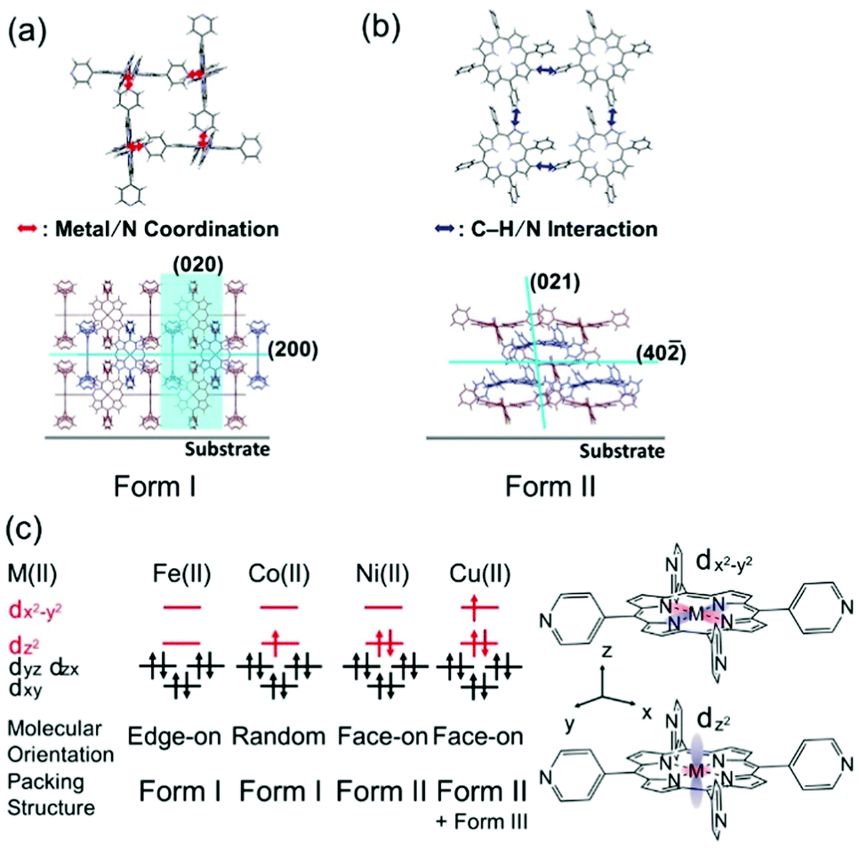 | ||
| Fig. 3 Schematics of the (a) form I and (b) II structures. (c) Schematic summary of the MTPyP film structures with the electron configurations of the porphyrin central metal ions.23,24 | ||
The CoTPyP film has several diffraction rings (Fig. 2b). Judging from the magnitude of the scattering vectors, these rings are also assigned to the reflections of the form I crystallite. This indicates that the polymorph is basically kept unchanged, but that the structure is disordered in terms of mosaicity by changing the central metal. Note that the crystal structure of CoTPyP has not been reported thus far, and that the present study is the first report of it. The disordered structure is confirmed by the atomic force microscopy (AFM) measurements: the topographic image of the FeTPyP film exhibits small crystalline grains (Fig. S2a, ESI†), while no such grains are observed in the CoTPyP film (Fig. S2b, ESI†).
To consider the reason for this difference in crystallinity, the electronic structures of the metal ions are discussed. According to former studies,23,24 the 3d orbital energy of the central metal ion splits as shown in Fig. 3c. The Fe(II) and Co(II) in porphyrins have different numbers of 3dz2 electrons; the 3dz2 orbitals of Fe(II) and Co(II) are empty and half-occupied, respectively. The intermolecular coordination bond of MTPyPs is formed by donation of the nitrogen lone-pair electrons of the pyridyl group to the unoccupied dz2 orbital of the metal ion.25,26 The interaction generates both σ bonding and σ* antibonding orbitals simultaneously, and the nitrogen lone-pair electrons are given priority to fill the unoccupied bonding orbital of FeTPyP. In the case of CoTPyP, however, an additional electron is in the antibonding orbital, resulting in a relatively weak coordination bond (Fig. 3c). This may be the reason why CoTPyP has a lower molecular aggregation propensity than that of FeTPyP. Based on this mechanism, the formation of the coordination bonds should be more suppressed for NiTPyP and CuTPyP, where the dz2 orbitals are fully occupied (Fig. 3c). This prediction is readily confirmed by the absence of the form I reflection spots in the diffraction patterns for Ni and Cu (Fig. 2c and d).
The diffraction patterns and the surface morphology of the NiTPyP and CuTPyP films, in fact, are similar to each other (Fig. 2c, d and Fig. S2c, d, ESI†), indicating that the two films have a common crystal structure. The diffraction pattern is newly recognized for these metal-coordinated compounds, but it has already been reported for free-base (metal free) TPyP27 (CCDC No. 749711; denoted “form II”). Indexing of the observed reflection spots in Fig. 2c and d was performed by referring to the simulation pattern of the form II crystal in Fig. S1b (see the ESI†). This crystal structure is characterized by a ruffled conformation of the porphyrin ring.27 Considering the ruffled conformation is energetically unfavorable for a single molecule,28 it should be induced by the intermolecular interaction around the molecule.
Since the (40![[2 with combining macron]](https://www.rsc.org/images/entities/char_0032_0304.gif) ) plane roughly parallel to the porphyrin ring (Fig. 3b) appears nearby the qz axis (Fig. 2c and d), the molecular orientation is categorized into the face-on type. In the form II structure, the C–H group of the porphyrin ring and the N atom of the pyridyl ring are closer than the van der Waals radius, suggesting that the C–H/N intermolecular interaction is actually at work.27 This intermolecular interaction thus forms a 2D network structure of the face-on arrangement.
) plane roughly parallel to the porphyrin ring (Fig. 3b) appears nearby the qz axis (Fig. 2c and d), the molecular orientation is categorized into the face-on type. In the form II structure, the C–H group of the porphyrin ring and the N atom of the pyridyl ring are closer than the van der Waals radius, suggesting that the C–H/N intermolecular interaction is actually at work.27 This intermolecular interaction thus forms a 2D network structure of the face-on arrangement.
Of note is that the CuTPyP film is characterized by another polymorph as a minor component as typically found for the reflections at qxy = 5.1 and qz = 5.9 nm−1 in Fig. 2d, which is not observed for NiTPyP (Fig. 2c). These Cu-specific reflection spots can be assigned to the triclinic crystal of free-base tetraphenylporphyrin (CCDC No. 1275315: see the simulation pattern in Fig. S1c, ESI†),29,30 where the porphyrin ring has the planar conformation.29 The new crystallite is referred to as “form III” in this paper. To explain the difference in crystal composition between CuTPyP and NiTPyP, let us go back to the electronic structures of the metal ions. In terms of electronic structure, these metal ions are distinguished by the number of dx2−y2 electrons, that is, Ni(II) has no electrons, and Cu(II) has one electron (Fig. 3c). The vacant orbital accepts an electron pair from the porphyrin N atom, but as the orbital occupancy increases, the electron-accepting capacity decreases. In fact, the intramolecular metal/N bonds in Cu porphyrins are generally weaker than those in Ni ones as shown by a longer bond length.31,32 This longer bond length is unfavorable for the ruffled conformation, which geometrically needs a shorter distance between the nitrogen atom and the metal ion.32,33 In this manner, the form II crystal with the ruffled porphyrin is suppressed in the CuTPyP film because of the electronic structure, and another crystallite, form III, is generated instead.
In this manner, the 2D-GIXD measurements have revealed that the supramolecular organization of MTPyPs depends strongly on the central metal ion, as summarized in Fig. 3c. The analytical results will further be confirmed by IR pMAIRS measurements with respect to molecular orientation and intermolecular interaction. For this purpose, the stretching vibration band of the pyridyl rings (ν(ring)py) is focused on as shown in Fig. 4, since the band is useful for orientation analysis and is sensitive to the metal/N coordination bond.34
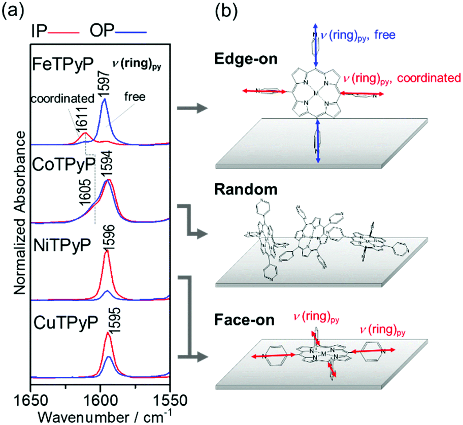 | ||
| Fig. 4 (a) IR pMAIRS spectra of the ν(ring)py region of the MTPyP films, and (b) schematics of the molecular orientation. The red and blue lines are the in-plane (IP) and out-of-plane (OP) absorption spectra, respectively. | ||
Fig. 4a shows the ν(ring)py band region of the IR pMAIRS spectra of the MTPyP films. The red and blue curves are the in-plane (IP) and out-of-plane (OP) absorption spectra, respectively. The band assignments were performed on the density functional theory calculation with the B3LYP/6-31G* basis set (Fig. S3e and Table S2, ESI†). The ν(ring)py band is commonly found at about 1595 cm−1 for all the metal ions, each of which has a satellite band at 1611 cm−1 for FeTPyP and 1605 cm−1 for CoTPyP. Previously reported IR spectra of pyridine exhibit a blueshift for the ν(ring)py band due to the intermolecular coordination bonding.34 Therefore, the stem band at about 1595 cm−1 is attributed to the free pyridyl ring; whereas the satellite band is assigned to the ν(ring)py mode of the coordinated pyridyl ring. The coexistence of different components found for FeTPyP and CoTPyP agrees with the schematic of the coordinated and free pyridyl rings involved in form I (Fig. 3a, and Fig. S1a, ESI†). Of further interest is, that the blue shift of FeTPyP is larger than that of CoTPyP, which suggests a tighter molecular arrangement for FeTPyP.
The IR pMAIRS spectra enable us to analyze the molecular orientation in the films. For FeTPyP, the IP and OP spectra are significantly different from each other: the band of the coordinated bond appears mainly in the IP spectrum, while the band of the free pyridine appears predominantly in the OP spectrum. Since the transition moment of the ν(ring)py mode is parallel to the C2 symmetry axis of the pyridyl ring, this result clearly implies that the axis of the coordinated pyridyl ring is parallel to the substrate surface; whereas the free one stands on the substrate perpendicularly as shown in Fig. 4b. This orientation is consistent with the edge-on crystal of form I revealed by the 2D-GIXD measurements in Fig. 3a. The CoTPyP film, on the other hand, exhibits IR pMAIRS spectra with nearly identical IP and OP spectra, indicating the random orientation. This result also agrees with the XRD results. In a similar manner, the stronger IP band confirms the face-on orientation of the porphyrin ring in both the NiTPyP and CuTPyP films, as shown schematically in Fig. 4b.
In summary, selective control of the edge-on and face-on orientations of MTPyPs has been achieved by changing the central metal ion of the porphyrin ring. When Fe(II) is introduced into the porphyrin ring, the Fe/N coordination bond generates a 2D metal–organic framework structure with the porphyrin ring perpendicular to the substrate. By introducing Ni(II) or Cu(II), on the other hand, the formation of the coordination bond is highly restricted, and instead the C–H/N intermolecular interaction between the porphyrin and pyridyl rings induces another supramolecular organization, in which the porphyrin ring is aligned parallel to the substrate. In this manner, the present study presents a novel strategy to control 2D supramolecular structures by changing the balance of the two different intermolecular interactions.
This work was financially supported by a Grant-in-Aid for Scientific Research (A) (No. 15H02185 (TH)), a Grant-in-Aid for Challenging Research (Exploratory) (No. 21K18979 (TH)), a Grant-in-Aid for Young Scientists (B) (No. 17K14502 (TS)), a Grant-in-Aid for Early-Career Scientists (No. 19K15602 (NS)), and a Grant-in-Aid for JSPS Fellows (No. 20J10803 (KT)) from the Japan Society for the Promotion of Science (JSPS), for which we are thankful.
Conflicts of interest
There are no conflicts to declare.Notes and references
- Y. Y. Noh, J. J. Kim, Y. Yoshida and K. Yase, Adv. Mater., 2003, 15, 699–702 CrossRef CAS.
- C. J. Mueller, E. Gann, C. R. Singh, M. Thelakkat and C. R. McNeill, Chem. Mater., 2016, 28, 7088–7097 CrossRef CAS.
- S. Y. Son, G. Y. Lee, S. Kim, W. T. Park, S. A. Park, Y. Y. Noh and T. Park, ACS Appl. Mater. Interfaces, 2019, 11, 10751–10757 CrossRef CAS PubMed.
- C. Lu, H. C. Chen, W. T. Chuang, Y. H. Hsu, W. C. Chen and P. T. Chou, Chem. Mater., 2015, 27, 6837–6847 CrossRef CAS.
- A. Zhang, C. Xiao, Y. Wu, C. Li, Y. Ji, L. Li, W. Hu, Z. Wang, W. Ma and W. Li, Macromolecules, 2016, 49, 6431–6438 CrossRef CAS.
- P. Wang, Y. Ma, P. Yin, D. Cai, S. Wan and Q. Zheng, Chem. Eng. J., 2021, 418, 129497 CrossRef CAS.
- C. Piliego, D. Jarzab, G. Gigli, Z. Chen, A. Facchetti and M. A. Loi, Adv. Mater., 2009, 21, 1573–1576 CrossRef CAS.
- C. J. Chiang, J. C. Chen, H. Y. Tsao, K. Y. Wu and C. L. Wang, Adv. Funct. Mater., 2015, 25, 606–614 CrossRef CAS.
- A. Kumar, A. K. Palai, T. J. Shin, J. Kwon and S. Pyo, New J. Chem., 2018, 42, 4052–4060 RSC.
- Z. Bao, A. J. Lovinger and A. Dodabalapur, Appl. Phys. Lett., 1996, 69, 3066–3068 CrossRef CAS.
- K. Xiao, Y. Liu, G. Yu and D. Zhu, Appl. Phys. A: Mater. Sci. Process., 2003, 77, 367–370 CrossRef CAS.
- N. Shioya, R. Murdey, K. Nakao, H. Yoshida, T. Koganezawa, K. Eda, T. Shimoaka and T. Hasegawa, Sci. Rep., 2019, 9, 1–7 CAS.
- T. Nakamura, N. Shioya, T. Shimoaka, R. Nishikubo, T. Hasegawa, A. Saeki, Y. Murata, R. Murdey and A. Wakamiya, Chem. Mater., 2019, 31, 1729–1737 CrossRef CAS.
- K. Akers, R. Aroca, A. M. Hort and R. O. Loutfy, Spectrochim. Acta, Part A, 1988, 44, 1129–1135 CrossRef.
- A. Sugie, W. Han, N. Shioya, T. Hasegawa and H. Yoshida, J. Phys. Chem. C, 2020, 124, 9765–9773 CrossRef CAS.
- Y. Watanabe, H. Sasabe and J. Kido, Bull. Chem. Soc. Jpn., 2019, 92, 716–728 CrossRef CAS.
- D. Yokoyama, H. Sasabe, Y. Furukawa, C. Adachi and J. Kido, Adv. Funct. Mater., 2011, 21, 1375–1382 CrossRef CAS.
- Y. Watanabe, D. Yokoyama, T. Koganezawa, H. Katagiri, T. Ito, S. Ohisa, T. Chiba, H. Sasabe and J. Kido, Adv. Mater., 2019, 31, 1–8 Search PubMed.
- T. Nakamura, N. Shioya, T. Hasegawa, Y. Murata, R. Murdey and A. Wakamiya, ChemPlusChem, 2019, 84, 1396–1404 CrossRef CAS PubMed.
- L. Pan, S. Kelly, X. Huang and J. Li, Chem. Commun., 2002, 2334–2335 RSC.
- J. M. S. Lopes, R. N. Sampaio, A. S. Ito, A. A. Batista, A. E. H. Machado, P. T. Araujo and N. M. B. Neto, Spectrochim. Acta, Part A, 2019, 215, 327–333 CrossRef CAS PubMed.
- T. Hasegawa and N. Shioya, Bull. Chem. Soc. Jpn., 2020, 93, 1127–1138 CrossRef CAS.
- H. Alt, H. Binder and G. Sandstede, J. Catal., 1973, 28, 8–19 CrossRef CAS.
- M. Zerner and M. Gouterman, Theor. Chim. Acta, 1966, 4, 44–63 CrossRef CAS.
- M. S. Liao and S. Scheiner, J. Chem. Phys., 2002, 116, 3635–3645 CrossRef CAS.
- W. R. Scheidt and C. A. Reed, Chem. Rev., 1981, 81, 543–555 CrossRef CAS.
- S. Lipstman and I. Goldberg, Acta Crystallogr., Sect. C: Cryst. Struct. Commun., 2009, C65, o447–o452 CrossRef PubMed.
- K. K. Anderson, J. D. Hobbs, J. A. Shelnutt, L. Luo, K. D. Stanley and J. M. E. Quirke, J. Am. Chem. Soc., 1993, 115, 12346–12352 CrossRef CAS.
- S. J. Silvers and A. Tulinsky, J. Am. Chem. Soc., 1967, 89, 3331–3337 CrossRef CAS PubMed.
- K. Tomita, N. Shioya, T. Shimoaka, K. K. Okudaira, H. Yoshida, T. Koganezawa and T. Hasegawa, Cryst. Growth Des., 2021, 21, 5116–5125 CrossRef CAS.
- A. L. Maclean, G. J. Foran, B. J. Kennedy, P. Turner and T. W. Hambley, Aust. J. Chem., 1996, 49, 1273–1278 CrossRef CAS.
- E. B. Fleischer, C. K. Miller and L. E. Webb, J. Am. Chem. Soc., 1964, 86, 2342–2347 CrossRef CAS.
- A. Plaza and J. Chojnacki, Acta Crystallogr., Sect. C: Cryst. Struct. Commun., 2012, C68, m24–m28 CrossRef PubMed.
- I. S. Perelygin and M. A. Klimchuk, J. Appl. Spectrosc., 1976, 24, 43–46 CrossRef.
Footnote |
| † Electronic supplementary information (ESI) available: Simulated 2D-GIXD patterns, AFM images of the MTPyP films, film preparation conditions, measurement conditions of GIXD, IR pMAIRS, and AFM, synthesis methods of MTPyP, and characterization data of MTPyPs. See DOI: 10.1039/d1cc06169k |
| This journal is © The Royal Society of Chemistry 2022 |