DOI:
10.1039/D2NJ00554A
(Paper)
New J. Chem., 2022,
46, 7433-7441
Renewable spent mushroom compost-derived carbon for solid-state supercapacitors as a sustainable alternative
Received
1st February 2022
, Accepted 17th March 2022
First published on 23rd March 2022
Abstract
The preparation of an environmentally benign, inexpensive supercapacitor electrode material from waste biomass, achieving useful carbon electrode production, is challenging. The present work aims to find a process for recycling spent mushroom compost into a useful supercapacitor electrode material. High-surface-area activated carbon derived from spent mushroom compost (SMC) is used as a catalyst electrode in a solid-state electrochemical double-layer capacitor (SSEDLC). The SMC is thermally activated at three different temperatures (SMC-700, SMC-800, and SMC-900) to achieve the optimal carbon content and activation temperature for improving electrode performance based on the surface area and pore structure. The SMC-derived nanostructured carbon exhibited a high specific surface area of 690 m2 g−1 in the case of SMC-800 upon activation, which strongly influences the specific and areal capacitance of the fabricated SSEDLC. Interestingly, the use of the prepared PVA/H2SO4 gel electrolyte showed a promising trend, with considerable capacitance retention of up to 90% over 3000 cycles obtained with the material optimized at 800 °C (SMC-800).
Introduction
Renewable energy production, storage, and transportation have become a primary research focus among the major world powers and the scientific community in changing the global landscape and overcoming the depletion of resources. As global energy consumption increases day by day, fossil fuels are taking the brunt of the continuous shift in consumer electronics to address the needs of an increasing population. The rapid depletion of fossil fuel resources has increased researchers’ attention in developing and refining more efficient sustainable energy materials and storage devices.1–4 Supercapacitors have been regarded as potential energy storage devices among the different energy storage technologies. Besides, they have high power density compared to Li-ion batteries and remarkable properties such as rapid charge–discharge rates, long cyclic performance, and high power density.1,2,5 Unlike batteries and fuel cells, supercapacitors can be customized in safe all-solid-state mode to make them much safer and lighter. Supercapacitors, also known as electrochemical double-layer capacitors (EDLCs), could be an alternative energy source for portable machines and the automobile industry due to their high storage capacity in combination with higher power density, acceptable energy density, long cycle life, and fast charge–discharge rates with high safety.1,2,6
An EDLC stores energy by collecting charges at the electrode–electrolyte interface. Activated carbon (AC) has been used as an electrode material in commercial EDLCs due to its larger surface area, superior electrochemical stability, electrical conductive qualities, corrosion resistance, and micro (<2 nm), and mesoporous (2–50 nm) character.5,6 However, the growing cost and scarcity of fossil fuels such as petroleum coke, oil pitches, and coal significantly impact and impede the large-scale manufacture of EDLC materials.7 The AC obtained from these materials is also not renewable. As a result of the rising research interest in converting sustainable material stocks for energy applications, bio-waste as a precursor for activated carbon production is enticing due to its cheap cost, availability, being inherently renewable, and also in terms of waste management.5–8 The different types of bio-waste-derived AC have shown differences in performance due to their diverse natures.9–11
In this work, we have studied the capacitance performance of AC derived from a spent mushroom substrate or compost (SMS or SMC). Mushroom substrate is often made out of straw, corncobs, hay, cottonseed hulls, and some other substances which have been used as growth media to produce mushrooms. After numerous mushroom collecting cycles, the productivity of mushrooms decreases, and the substrate is considered “spent.” The spent mushroom base is a by-product of the mushroom production process.12 China, which is now the world's largest mushroom exporter, accounts for more than 70% of worldwide mushroom production. According to the Chinese Academy of Agricultural Sciences, the yearly production of mushrooms was around 28 million tonnes in 2012. SMS is created at a rate of 4 to 5 kg for every kilogram of mushrooms cultivated.12–14
One of the main limitations of commercially available EDLCs is the use of liquid electrolytes, which cause electrolyte leakage, the possibility of a parasitic reaction, corrosion, and packing challenges, all of which further limit large-scale EDLC production.15 Moreover, the release of hazardous by-products into the environment takes place from the liquid electrolyte.16 Polymer-based electrolytes, on the other hand, can be used as an alternative to liquid electrolytes, because they have good physical contact with the current metal collectors, high durability, excellent ionic conductivity, a larger potential window for improved energy density, a simplified concept, processability, and are far more reliable, environmentally sustainable, and safe to handle.17–19 Song et al. reported that metal oxalates (M2C2O4) have been shown to be ideal sacrificial additives for pre-metalation with sufficient metal ion release in a metal ion capacitor due to their high irreversible capacity, stability in air, absence of residue, and low cost.20 The Xiaobo Ji et al. group prepared carbon quantum dots and their derivative 3D porous carbon frame shows higher sodium-ion battery performance and ultrafast rate capability.21
To the best of the authors’ knowledge, this is the first study to report the use of mushroom bio-waste compost as electrode materials in all-solid-state supercapacitors. Herein, the spent mushroom composite carbon was activated using KOH at different carbonization temperatures (700, 800, and 900 °C). As-prepared activated carbon was employed to make a supercapacitor, and the electrochemical behaviour of the solid-state device was evaluated using galvanostatic charge–discharge (GCD) and cyclic voltammetry (CV) experiments using a 0.5 M H2SO4 electrolyte and an active area of 1 cm2. Subsequently, a symmetric supercapacitor was developed with a solid-state electrochemical double-layer capacitor (SSEDLC) with an active area of 4 cm2, using three different heat-treated samples, and it was tested for electrochemical performance in a PVA/H2SO4 gel electrolyte.
Experimental section
Preparation of activated carbon from spent mushroom compost
The mesoporous carbons were synthesized from SMC. In short, the SMC was cleaned several times with de-ionized water before being preheated at 100 °C for 24 h. Then, the required amount of preheated SMC was immersed in 10% KOH for 24 h and dried at 150 °C for 4 h. Subsequently, the aforesaid admixture was pyrolyzed for 4 h at 700 °C in an N2 atmosphere. The pyrolyzed samples were then rinsed several times with dilute HCl, accompanied by Milli-Q water, until the pH reached 7. The above-mentioned product was eventually dried at 100 °C for 12 h, and is denoted SMC-700. Similarly, the above procedure was used to synthesize SMC-800 and SMC-900 with temperatures of 800 and 900 °C.
Material characterization
The pore size, BET surface area, and pore distribution were characterized using an ASAP 2020 instrument and calculated by the BET and BJH methods. Raman spectra were recorded at ambient temperature using a Nanophoton Raman-11 spectrometer and an Nd-YAG laser with a 532 nm line. Powder X-ray diffraction (XRD) measurements were recorded using a BRUKER-binary V3, with a range of 10 to 80° at a scan rate of 3° per minute. Surface morphology was examined with a field emission scanning electron microscopy (FE-SEM)- TESCAN MIRA 3 instrument coupled with energy dispersive X-ray spectrometry (EDX). An FEI TWIN 300 kV field emission gun Tecnai G2 microscope was used to capture high-resolution transmission electron microscopy (HR-TEM) images. X-Ray photoelectron spectroscopy (XPS) was used to determine the chemical oxidation state (Omicron nanotechnology instrument).
Conventional three-electrode system
The electrochemical experiments were carried out with standard three-electrode electrochemical configurations. The counter and reference electrodes were made of Pt mesh and Ag/AgCl, respectively. To make a slurry, 14 mg of SMC, 4 mg of Vulcan carbon, 2 mg of 5% polyvinylidene fluoride (PVDF), and 200 μL of N-methyl-2-pyrrolidone (NMP) were mixed and ground for 1 h. The required amount of the above slurry was uniformly spread on a mild steel (thickness of 0.5 mm, MS) sheet with an active area of 1 cm2 and dried stepwise at 50 °C followed by 130 °C for 1 h. The mass loading of active SMC materials on the MS disk surface was maintained at about 0.5 ± 0.02 mg cm−2. CV measurements were performed between 0 and 0. 8 V vs. Ag/AgCl at various sweep rates ranging from 2 to 50 mV s−1 in 0.5 M H2SO4 electrolyte.
Fabrication of SMC electrodes and symmetric supercapacitors
The SSEDLC electrodes were prepared by the drop-casting method. In brief, 36 mg of SMC, 4 mg of PVDF, and 600 μL of NMP were mixed and ground for 1 h. The above mixture was coated on mild steel with an active area of 4 cm2 and dried stepwise at 50 °C followed by 130 °C for 1 h. The active substance loading on each electrode was specified to be 0.5 ± 0.02 mg cm−2. PVA was used to make a gel electrolyte of PVA/H2SO4, which was formed as follows. In brief, 1.5 g of PVA was blended with 90 mL of boiling water (70 °C) and stirred continuously for 1 h. The aforementioned solution was then treated with 30 mL of 0.5 M H2SO4 while being constantly stirred until a gel-like solution formed.
SSEDLC fabrication and electrochemical studies
The symmetric supercapacitors were fabricated by sandwiching the prepared SMC electrode face-to-face separated by a polypropylene separator immersed in PVA/H2SO4 gel electrolyte for 1 h. The assembly of electrode–separator/polyelectrolyte–electrode was standardized in device form in the air at room temperature. Further, the device was sealed in the membrane electrode assembly by hot-pressing the polypropylene sheet (immersed in PVA/H2SO4 gel electrolyte) between electrodes (SMC-coated electrode) at 1 kg cm−2 and 80 °C for 1 min. The electrochemical properties of the activated electrode were investigated using CV and GCD on a two-electrode set-up with a potential range of 0 to 0.8 V. Furthermore, the electrochemical characteristics of the SSEDLCs were investigated using CV at various scan speeds ranging from 2 to 50 mV s−1 and a GCD test for a voltage of 0.8 V at various currents. Electrochemical impedance spectroscopy (EIS) was studied at OCV. The cycle life of a supercapacitor was measured for 3000 cycles at a current density of 2 A g−1. All the foregoing electrochemical investigations were carried out at room temperature using the Autolab PGSTAT-30 workstation.
Results and discussion
Simultaneous carbonization and KOH activation
Scheme 1 shows the preparation of spent mushroom compost-derived biomass carbon, characterization, electrode assembly, and performance outcome. KOH activation is a promising method of simultaneous carbonization and activation of biomass via carbon corrosion followed by K2CO3 intermediate formation. KOH and K2CO3 lead to oxidation of carbon and reduction of the hydroxyl group, which tailors the formation of highly porous carbon.22 The SMC-derived carbon activation method can be explained. The spent mushroom compost, soaked in 10% KOH over 24 h for activation, might be diffused, with the entire biomass being adsorbed before the temperature was raised to above 500 °C. Micropores are created due to the carbon surface corrosion that occurs with KOH as given in reaction eqn (1). Further increasing the temperature from 700 to 900 °C yielded K2CO3 which decomposed to carbon monoxide/carbon dioxide gases and the formation of metallic potassium leading to pore size enlargement.23| | | 6KOH + 2C → 2K + 3H2↑ + 2K2CO3 | (1) |
| | | K2CO3 + 2C → 2K + 3CO↑ | (2) |
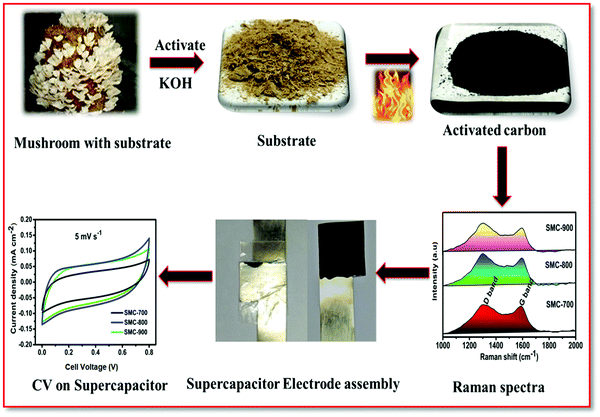 |
| | Scheme 1 An illustration of the stepwise preparation of activated carbon (SMC) derived from spent mushroom compost, electrode assembly, and supercapacitor performance. | |
BET, XRD, and Raman spectra studies
Fig. 1(a and b) show the surface area analysis of the prepared SMCs (SMC-700, SMC-800, SMC-900) by the characteristic nitrogen (N2) adsorption–desorption isotherm and pore size distribution. The adsorption–desorption isotherm is observed for all the SMC materials and has a hysteresis loop of relative pressure (P/P0) > 0.4 and describes the presence of mesopores in the range of 2–50, as shown in Fig. 1(a). Furthermore, the low-pressure hysteresis (P/P0 < 0.4) implies the presence of micropores (<2 nm). The highest BET-specific area of 690 ± 20 m2 g−1 was obtained for the SMC-800 sample. On the other hand, SMC-700 and SMC-900 revealed specific surface areas of 390 and 480 ± 20 m2 g−1, respectively. Likewise, the SMC-800 sample had a high pore volume of 0.69 cm3 g−1, whereas SMC-700 had 0.36 cm3 g−1 and SMC-900 had 0.41 cm3 g−1. Interestingly, the pore size distribution showed that the SMCs contain well-developed mesopores with only a few micropores. The micro-mesopore and mesopore proportions of the SMCs are ∼2–4 nm and ∼7–30 nm, respectively.8,24
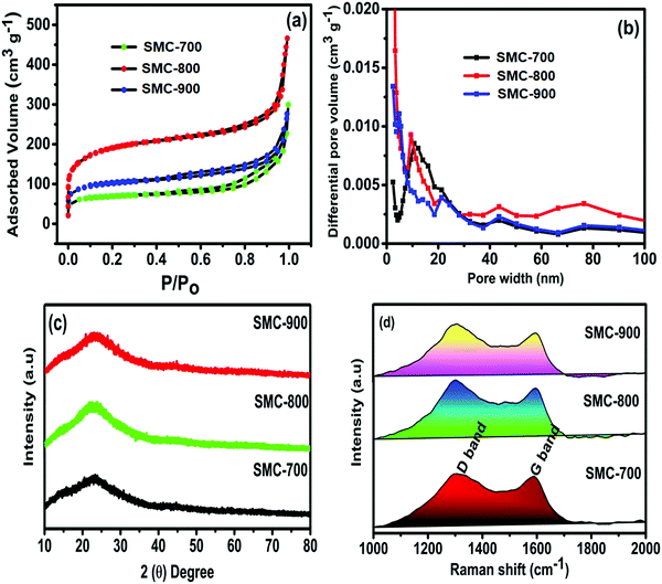 |
| | Fig. 1 (a) N2 adsorption–desorption isotherms, (b) pore size distributions, (c) XRD patterns, and (d) Raman spectra of SMC-derived carbon. | |
XRD patterns of SMCs pyrolyzed at different temperatures are represented in Fig. 1(c). The XRD exhibited a broad diffraction (2θ) peak at 23.4°, corresponding to the (002) plane reflection signature of the amorphous nature of activated carbon. No other secondary peak or impurity was observed, which is in good agreement with earlier reports in the literature.5,14,24 Further, the Raman spectra provide information about microstructures and confirmation of activated carbon, substantiating the highly disordered carbon structure. The carbon-dangling bond vibrations, which correspond to the sp3 configuration of a disordered D band, are responsible for the peak at around 1352 cm−1. This peak indicates the breathing mode vibration of A1g and, thus, confirms the presence of dangling bond carbon atoms such as carbon–oxygen. The line at 1561 cm−1 is attributed to the in-plane stretching vibrational modes of E2g in the graphitic carbon sp2 structure.6,25
The degree of defects/disorder in the carbon materials is obtained from the D and G band intensity ratio (ID/IG). The measured ID/IG of 1.01, 1.03, and 1.0 correspond to SMC-700, SMC-800, and SMC-900, respectively. The crystallite size (La) was calculated from the obtained ID/IG value using eqn (5).26
| |  | (5) |
where
La and
λ are the average crystallite size (nm) and wavelength of the laser used in the Raman measurement (
λ = 532 nm). According to the above equation, the calculated
La values of 19.03, 18.64, and 19.22 nm are ascribed to SMC-700, SMC-800, and SMC-900, respectively. The crystallite size value of SMC-800 is lower than those of SMC-700 and SMC-900. This smaller size might reduce the diffusion path-length of the ions’ charge–discharge process, which is beneficial for the capacitance performance.
FESEM, TEM, and XPS studies
The morphological characteristics of bio-waste-based activated carbon SMC-700, SMC-800, and SMC-900 were evaluated using FE-SEM images, as represented in Fig. 2(a–c). The surface morphology of the SMCs shows a highly porous morphology. SMC-800 exhibits a pore-like interconnected network structure and holds the highest BET surface area among the other activated carbons like SMC-700 and SMC-900. Besides, Fig. 2(d–f) shows the TEM image of SMC 800 consisting of a porous morphology. Furthermore, Fig. 2(f) indicates that SMC-800 has particularly porous characteristics as well as showing the formation of amorphous graphitic carbon.
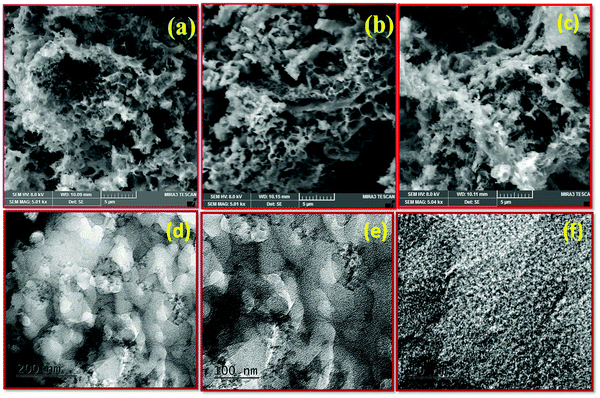 |
| | Fig. 2 FE-SEM images of (a) SMC-700, (b) SMC-800, and (c) SMC-900, and TEM images of (d–f) SMC-800. | |
Furthermore, XPS measurements were used to identify the chemical oxidation state and surface functional groups of SMC-800. The XPS survey spectrum in Fig. 3(a) shows the primary peaks of carbon and oxygen, with no other impurities observed. Fig. 3(b) depicts the deconvolution of the C 1s area into three different binding energy peaks, as 284.6 (C1), 286.1 (C2), and 288.4 (C3) assigned to the graphitic (CC)/CH, hydroxyl (COH) or phenol/ether (CO), and carbonyl/quinone groups (C![[double bond, length as m-dash]](https://www.rsc.org/images/entities/char_e001.gif) O), respectively.27,28Fig. 3(c) depicts the O 1s region deconvoluted into four different regions, namely O1, O2, O3, and O4. Peak O1 at binding energy 531.1 eV is attributed to oxygen double bonded to carbon/carbonyl (CO), peak O2 at binding energy 532.8 eV can be assigned to the effects of singly bonded oxygen (–O–) in C–O groups, peak O3 at binding energy 537.1 eV is ascribed to chemisorbed oxygen and water molecules, and peak O4 at binding energy 539.2 eV is due to OH groups like those in cyclohexanol or phenol.29–31
O), respectively.27,28Fig. 3(c) depicts the O 1s region deconvoluted into four different regions, namely O1, O2, O3, and O4. Peak O1 at binding energy 531.1 eV is attributed to oxygen double bonded to carbon/carbonyl (CO), peak O2 at binding energy 532.8 eV can be assigned to the effects of singly bonded oxygen (–O–) in C–O groups, peak O3 at binding energy 537.1 eV is ascribed to chemisorbed oxygen and water molecules, and peak O4 at binding energy 539.2 eV is due to OH groups like those in cyclohexanol or phenol.29–31
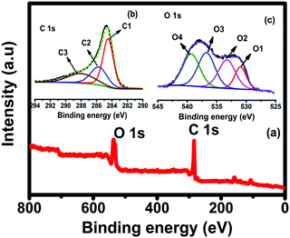 |
| | Fig. 3 XPS spectra of SMC-800: (a) survey, (b) carbon 1s, and (c) oxygen 1s spectra. | |
Electrochemical performance
The electrochemical performances of the synthesized SMC catalysts were first evaluated in a conventional three-electrode set-up in a 0.5 M sulfuric acid (H2SO4) aqueous electrolyte solution. Fig. 4(a–c) show the CV curves of SMC-700, 800, and 900 electrodes with different scan rates of about 2 to 25 mV s−1. Fig. 4(d) shows the comparative CV curves of three different temperature-treated SMCs at a scan rate of 2 mV s−1. It depicts a quasi-rectangular shape, indicating the existence of pseudocapacitance due to the presence of a reversible redox reaction, with oxygen functional groups like hydroxyl (C–OH), carbonyl (C–O), and H+ ions commonly occurring.32,33 Among the SMCs, SMC-800 exhibits a larger area under the curve, suggesting higher capacitance storage than SMC-700 or SMC-900. The areal capacitance of SMC-800 was observed to be 27 mF cm−2 at 2 mV s−1, which is higher than SMC-700 (20 mF cm−2) or SMC-900 (24 mF cm−2).
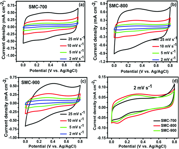 |
| | Fig. 4 (a–c) CV curves at different scan rates for SMC-700, 800, and 900, and (d) CV curves at a scan rate of 2 mV s−1. | |
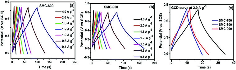
Fig. 5(a and b) depict the charge–discharge curves for SMC-800 and SMC-900 with different current densities. The charge–discharge curve at a high current density of 2 A g−1 delivered a high specific capacitance of 55 F g−1 for SMC-800, as represented in Fig. 5(c). Whereas the cases of SMC-700 and SMC-900 delivered maximum specific capacitance of 31 and 35 F g−1, respectively. The SMC-800 electrode revealed higher capacitance than SMC-700 or SMC-900, which is related to the specific surface area values of the electrode materials. Among these three electrodes, SMC-800 obtained a high specific surface area (690 m2 g−1) that allowed facile charge accessibility through the mesoporous carbon surface. The SMC-800 electrode material contains mesoporosity conducive for electrolyte ion access on the microspores of the carbon surface which formed a double layer. In contrast, SMC-700 (390 m2 g−1) and SMC-900 (480 m2 g−1) have a comparatively low surface area compared with SMC-800, which is reflected in the capacitance values. The relationships between discharge current and scan rate between 2 and 25 mV s−1 at 0.8 V of SMC-700, 800, and 900 reveal that SMC-800 exhibits linear discharge current behaviour with H2SO4 solution. Linear discharging characteristics suggest that electrolyte ion diffusion into the bulk electrode is better and narrower.34,35 The mean areal capacitance of SMC-800 is observed to be 27 mF cm−2 as compared to SMC-700 (19 mF cm−2) and SMC-900 (22 mF cm−2).
 |
| | Fig. 5 (a and b) Charge–discharge curves at different current densities for SMC-800 and 900, and (c) a GCD comparison at 2 A g−1. | |
Fig. 6(a and b) show the CV of fabricated SSEDLS with an active area of 4 cm2 using PVA/H2SO4 gel electrolyte at different scan rates for SMC-700 and SMC-800. Fig. 6(c) shows nearly rectangular behaviour for SMC-700, 800, 900, and commercial Vulcan carbon with a scan rate of 5 mV s−1. In addition, the areal capacitance of SMC-800 increased to 15 mF cm−2 at 5 mV s−1, as compared to SMC-700 (10 mF cm−2) and SMC-900 (12 mF cm−2). In addition, the areal capacitance vs. scan rate from 2 to 50 mV s−1 at 0.8 V with PVA/H2SO4 used as a gel electrolyte is shown in Fig. 6(d). The bio-waste-derived SMC carbon with optimum temperature used for SSEDLC delivered a high specific capacitance of 34 F g−1 using PVA/H2SO4 as a gel electrolyte. The areal capacitance of SMC-800 was found to be 13 mF cm−2 in contrast to SMC-700 (8 mF cm−2) and SMC-900 (10 mF cm−2).
 |
| | Fig. 6 CV curves of SSEDLCs with an active area of 4 cm2 at different scan rates for (a) SMC-700 and (b) 800, (c) CV curves at a scan rate of 5 mV s−1, and (d) areal capacitance vs. scan rate for SMC-700, 800, and 900. | |
The capacitance performance of SMC-800 SSEDLCs using a PVA/H2SO4 gel electrolyte was examined through the GCD test, as shown in Fig. 7(a). The charge and discharge behaviour of the current density at 1 A g−1 is superior to that of other current densities. The three SMC GCD traces in PVA/H2SO4 gel electrolyte performance are represented in Fig. 7(b). The GCD characteristic triangular charge–discharge trend for PVA/H2SO4 explicated the electric double layer with some redox capacitive behaviour contributions from impurities in the residual carbon. Plots of specific capacitance with varying current densities are represented in Fig. 7(c). High specific capacitance is achieved for SMC-800 (34 F g−1) compared to SMC-700 and 900 (20 and 25 F g−1) at 1 A g−1.
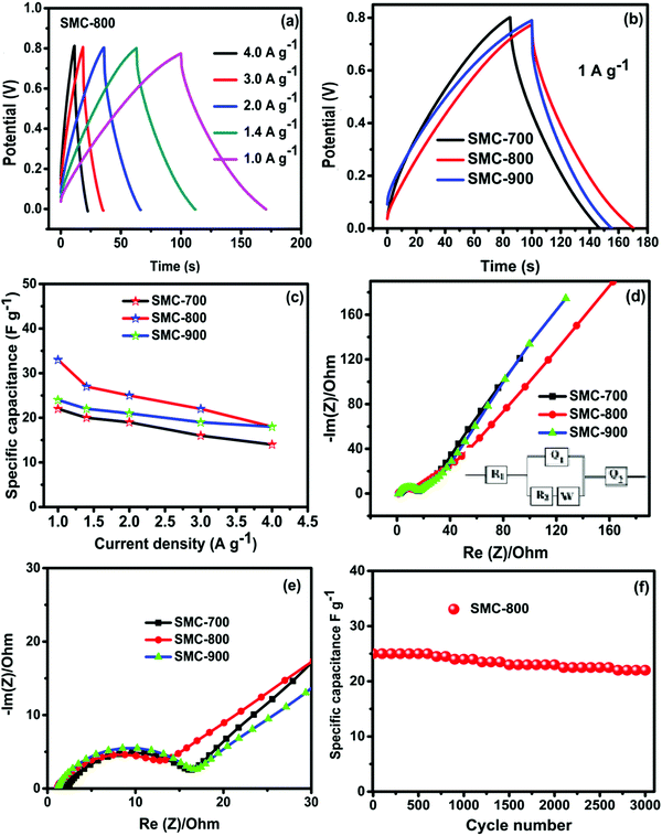 |
| | Fig. 7 (a) Charge–discharge curves at different current densities for SMC-800, (b) charge–discharge curves at 1 A g−1 for all synthesized materials, (c) plots of specific capacitance vs. current density, (d) Nyquist plots in PVA/H2SO4 under OCV conditions, (e) an expanded view of the Nyquist plots, and (f) specific capacitance vs. cycle number at 2 A g−1. | |
The electrochemical conductivity and charge storage kinetics of the as-prepared materials were investigated using EIS measurements at open-circuit voltage. The Nyquist plots of the freshly constructed SMC electrodes are shown in Fig. 7(d and e). The high-frequency depressed semicircular part intersecting on the x-axis is ascribed to the electrochemical series resistance (Rs), and the medium frequency part corresponds to the electrode porosity and thickness of ion migration through the electrode–electrolyte region (Rct). At low frequency, sections along the imaginary axis, such as straight lines, represent the capacitive nature signature (C1). The respective Randles circuit models were fitted, and the results are given in Table 1. The obtained Rs, Rct, and C1 values are given in Table 1. Among these three-electrodes, SMC-800 revealed lower Rs (0.95 Ω), Rct (6.95 Ω), and Warburg resistance than the SMC-700 and SMC-900 electrodes. These results were reflected in the supercapacitor performance capacitance value of the SMC-800 electrode.36,37
Table 1 EIS fitted values for the as-prepared SMC 700, SMC 800, and SMC 900 electrodes
| Electrode |
R
s (Ohm) |
C1 (F) |
R
ct (Ohm) |
W (Ohm s−1/2) |
Q2 (F sa−1) |
a2 |
| SMC 700 |
2.45 |
0.0043 |
10.41 |
8.143 |
4.257 × 10¹² |
0.98 |
| SMC 800 |
0.95 |
0.0081 |
6.95 |
0.162 |
0.044 |
0.456 |
| SMC 900 |
0.96 |
0.0060 |
10.55 |
3.563 |
0.139 |
0.323 |
An electrode stability test was carried out for optimized material SMC-800 with SSEDLCs at 2 A g−1 for 3000 cycles, as represented in Fig. 7(f). The optimal heat-treated sample for SMC-800 with PVA/H2SO4 gel electrolyte has excellent retention ability and preserves 90% of specific capacitance. The preeminent cycle life of the biomass-derived SMC-800 can be explained as follows. The SMC-800 electrode material comprises a three-dimensional surface morphology structure that yielded micro and mesopores (Fig. 2(b)). The SMC-800 three-dimensional morphology aided the continuous stress-free charge adsorption and desorption process on the electrode surface. However, 10% capacitance degradation occurred after 3000 cycles. This degradation might be because some of the micropores became damaged/blocked during the prolonged cycling process which led to reduced electrode performance. Based on these results, a high surface area activated carbon from waste mushroom composite (SMC-800) with an optimal temperature has enhanced supercapacitor behaviour and endurance in energy storage applications and could be responsible for actively enriching future energy storage.
Conclusions
In the present work, high-surface-area bio-waste-based activated carbon electrodes were developed for utilization in an all-solid-supercapacitor. An areal capacitance of 27 mF cm−2 at 2 mV s−1 was obtained for SMC-800, which is higher than for SMC-700 or 900. SMC-800 shows a higher specific capacitance of 34 F g−1 when used in SSEDLCs with a PVA/H2SO4 gel electrolyte. In addition, SMC-800 shows excellent cycling stability and retains 90% of the initial specific capacitance over 3000 cycles. Moreover, the present results propose the bio-waste spent mushroom compost-derived activated carbon to be an alternative and sustainable material source for future energy storage devices. The study also provides a zero-solid-waste disposal method, protecting the environment via generating green energy materials.
Author contributions
P. Dhanasekaran: methodology development, formal analysis, and validation, writing original draft and editing; Dr Deivasigamani Ranjith Kumar: characterization, data curation, durability studies, and editing; Dr Jae-Jin Shim: investigation, review and editing; Dr D. Kalpana: supervision, financial support, review, and editing. All authors have read and agreed to the published version of the manuscript.
Conflicts of interest
There are no conflicts of declare.
Acknowledgements
P. Dhanasekaran thanks CSIR-for a Senior Research Associateship (Scientist's Pool Scheme-9123-A). Thanks to Director, CSIR-CECRI for her valuable guidance and support. Institutional Review Board Statement: CSIR-CECRI contribution number CECRI/PESVC/Pubs/2022-012.
References
- W. Chen, R. B. Rakhi, L. Hu, X. Xie, Y. Cui and H. N. Alshareef, Nano Lett., 2011, 11, 5165–5172 CrossRef CAS PubMed.
- P. Simon and Y. Gogotsi, Nat. Mater., 2008, 7, 845–854 CrossRef CAS PubMed.
- P. Dhanasekaran and N. M. Gupta, Int. J. Hydrogen Energy, 2012, 37, 4897–4907 CrossRef CAS.
- P. Dhanasekaran, S. Vinod Selvaganesh and S. D. Bhat, New J. Chem., 2017, 41, 2987–2996 RSC.
- S. T. Senthilkumar, R. K. Selvan, Y. S. Lee and J. S. Melo, J. Mater. Chem. A, 2013, 1, 1086–1095 RSC.
- S. T. Senthilkumar, B. Senthilkumar, S. Balaji, C. Sanjeeviraja and R. Kalai Selvan, Mater. Bull., 2011, 46, 413–419 CrossRef CAS.
- L. Wei and G. Yushin, Nano Energy, 2012, 1, 552–565 CrossRef CAS.
- S. T. Senthilkumar, R. K. Selvan, J. S. Melo and C. Sanjeeviraja, ACS Appl. Mater. Interfaces, 2013, 5, 10541–10550 CrossRef CAS PubMed.
- N. Sudhan, K. Subramani, M. Karnan, N. Ilayaraja and M. Sathish, Energy Fuels, 2017, 31, 977–985 CrossRef CAS.
- H. Lu and X. S. Zhao, Sustainable Energy Fuels, 2017, 1, 1265–1281 RSC.
- M. Hubbe, M. Nazhad and C. Sánchez, BioResources, 2010, 5, 2808–2854 CrossRef.
- Y. Ma, Q. Wang, X. Sun, X. Wang, W. Su and N. Song, BioResources, 2014, 9, 3939–3954 Search PubMed.
- W. M. Law, W. N. Lau, K. L. Lo, L. M. Wai and S. W. Chiu, Chemosphere, 2003, 52, 1531–1537 CrossRef CAS.
- C.-W. Phan and V. Sabaratnam, Appl. Microbiol. Biotechnol., 2012, 96, 863–873 CrossRef CAS.
- W. G. Pell and B. E. Conway, J. Power Sources, 2004, 136, 334–345 CrossRef CAS.
- S. Hu, R. Rajamani and X. Yu, Appl. Phys. Lett., 2012, 100, 104103 CrossRef.
- C. Ramasamy, J. Palma del vel and M. Anderson, J. Solid State Electrochem., 2014, 18, 2217–2223 CrossRef CAS.
- H. Yu, J. Wu, L. Fan, K. Xu, X. Zhong, Y. Lin and J. Lin, Electrochim. Acta, 2011, 56, 6881–6886 CrossRef CAS.
- F. Barzegar, J. K. Dangbegnon, A. Bello, D. Y. Momodu and N. Manyala, AIP Adv., 2015, 5, 097171 CrossRef.
- Z. Song, G. Zhang, X. Deng, K. Zou, X. Xiao, R. Momen, A. Massoudi, W. Deng, J. Hu, H. Hou, G. Zou and X. Ji, Nano-Micro. Lett., 2022, 14, 53 CrossRef CAS PubMed.
- H. Hou, C. E. Banks, M. Jing, Y. Zhang and X. Ji, Adv. Mater., 2015, 27, 7861–7866 CrossRef CAS PubMed.
- J. Wang and S. Kaskel, J. Mater. Chem., 2012, 22, 23710–23725 RSC.
- K. Li, W. Chen, H. Yang, Y. Chen, S. Xia, M. Xia, X. Tu and H. Chen, Bioresour. Technol., 2019, 280, 260–268 CrossRef CAS.
-
M. J. Lazaro, V. Celorrio, J. I. Pardo, S. Perathone and R. Moliner, Study and application of carbon black vulcan XC-72R in polymeric electrolyte fuel cells, Nova Science Publishers, Inc, 2011, Chapter 2 Search PubMed.
- A. Jänes, H. Kurig and E. Lust, Carbon, 2007, 45, 1226–1233 CrossRef.
- D. R. Kumar, I. Kanagaraj, G. Dhakal, A. S. Prakash and J.-J. Shim, J. Environ. Chem. Eng., 2021, 9, 105698 CrossRef CAS.
- P. Dhanasekaran, S. Vinod Selvaganesh, A. Shukla, N. Nagaraju and S. D. Bhat, Electrochim. Acta, 2018, 263, 596–609 CrossRef CAS.
- A. M. Puziy, O. I. Poddubnaya, R. P. Socha, J. Gurgul and M. Wisniewski, Carbon, 2008, 46, 2113–2123 CrossRef CAS.
- P. Dhanasekaran, S. Vinod Selvaganesh and S. D. Bhat, J. Power Sources, 2016, 304, 360–372 CrossRef CAS.
- C.-T. Hsieh and H. Teng, Carbon, 2002, 40, 667–674 CrossRef CAS.
- H. Valdés, M. Sánchez-Polo, J. Rivera-Utrilla and C. A. Zaror, Langmuir, 2002, 18, 2111–2116 CrossRef.
- E. Frackowiak, J. Braz. Chem. Soc., 2006, 17, 1074–1082 CrossRef CAS.
- D. S. Su and R. Schlögl, ChemSusChem, 2010, 3, 136–168 CrossRef CAS PubMed.
- H. Yu, L. Fan, J. Wu, Y. Lin, M. Huang, J. Lin and Z. Lan, RSC Adv., 2012, 2, 6736–6740 RSC.
- Z. Niu, H. Dong, B. Zhu, J. Li, H. H. Hng, W. Zhou, X. Chen and S. Xie, Adv. Mater., 2013, 25, 1058–1064 CrossRef CAS PubMed.
- D. Hulicova, M. Kodama and H. Hatori, Chem. Mater., 2006, 18, 2318–2326 CrossRef CAS.
- S. Roldán, I. Villar, V. Ruíz, C. Blanco, M. Granda, R. Menéndez and R. Santamaría, Energy Fuels, 2010, 24, 3422–3428 CrossRef.
Footnote |
| † Authors contributed equally to this work. |
|
| This journal is © The Royal Society of Chemistry and the Centre National de la Recherche Scientifique 2022 |

 a,
Deivasigamani Ranjith
Kumar†
a,
Deivasigamani Ranjith
Kumar†


