 Open Access Article
Creative Commons Attribution 3.0 Unported Licence
A review of oligo(arylene ethynylene) derivatives in molecular junctions
Luke J.
O'Driscoll
 * and
Martin R.
Bryce
 *
*
Department of Chemistry, Durham University, Lower Mountjoy, Stockton Road, Durham, UK DH1 3LE. E-mail: luke.j.odriscoll@durham.ac.uk; m.r.bryce@durham.ac.uk
First published on 10th June 2021
Abstract
Oligo(arylene ethynylene) (OAE) derivatives are the “workhorse” molecules of molecular electronics. Their ease of synthesis and flexibility of functionalisation mean that a diverse array of OAE molecular wires have been designed, synthesised and studied theoretically and experimentally in molecular junctions using both single-molecule and ensemble methods. This review summarises the breadth of molecular designs that have been investigated with emphasis on structure–property relationships with respect to the electronic conductance of OAEs. The factors considered include molecular length, connectivity, conjugation, (anti)aromaticity, heteroatom effects and quantum interference (QI). Growing interest in the thermoelectric properties of OAE derivatives, which are expected to be at the forefront of research into organic thermoelectric devices, is also explored.
1 Introduction
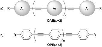
Oligo(arylene ethynylene)s (OAEs) consist of (hetero)aromatic ring systems linked by alkynes in an alternating fashion (Fig. 1a). The prototypical OAE is oligo(phenylene ethynylene) (OPE) (Fig. 1b). OAEs have found applications in diverse fields, including biosensors and biocides1 (including recently against the SARS-CoV-2 virus2), supramolecular chemistry3–5 and sensors,6,7 covalent organic frameworks,8 organic photovoltaics,9 and liquid crystals.10 Synthetically, OAEs have been used as graphene nanoribbon precursors11 and OAE templates have been used to prepare OAE macrocycles.12 OAEs have even been applied to the design of anthropomorphic molecules.13 This review focuses on OAEs designed for use in molecular electronics applications, specifically in molecular junction experiments, where the OAE forms the conjugated, conductive backbone of a molecular wire held between two electrodes.This review aims to highlight the chemical diversity of OAE derivatives and to discuss the impact of structural variation on their electronic and thermal properties in molecular junctions. Work in this field is highly interdisciplinary, combining chemical synthesis of bespoke molecules, experimental studies of their assembly and transport properties in junctions, and computational studies that provide insights into the experimental results. The topic is approached from a chemical viewpoint, but to provide appropriate context this introduction will include a concise overview of experimental and theoretical methods used in the study of molecular junctions.
1.1 Nomenclature
OAE molecular wires used in molecular junctions incorporate two essential structural features: (i) the OAE backbone itself and (ii) anchoring units to attach this backbone to electrodes (in some cases, anchoring groups also form part of the OAE backbone, e.g. terminal pyridine rings). A third feature that is often present is additional “side group” functionality, e.g. alkyl chains to enhance solubility. Section 2 provides a detailed discussion of the structural variation of OAEs.This review will follow the usual convention in molecular electronics of naming OAEs (especially OPEs) based on the number of aromatic units present in the backbone. Hence when n = 1, the molecule shown in Fig. 1b is an OPE3. Shorter molecules, e.g. OAE2 derivatives (tolanes, n = 0) are commonly studied. Studies of OPE series often include species based on a single benzene ring. They will be considered within this review where they serve as model compounds in this manner. Note that although benzene derivatives are sometimes referred to as OPE1 in this context, these species are not truly OPEs (they are not oligomers and do not contain ethynylene fragments).
Using this nomenclature, aromatic systems always form the termini of an OAE backbone; any additional functionality, even extra alkynes, will be considered either as anchoring groups or side groups, as appropriate. As discussed below, para-conjugated systems are favoured for high conductance and this review will consider this to be the default geometry; any deviation from all-para geometry will be emphasised. Note that it is common, but not necessary, for OAEs studied in molecular junctions to be symmetrical; this facilitates synthesis and prevents potential complexity regarding the orientation of molecules within a junction.
The scope of this review will extend to molecules in which arylene ethynylene backbones are used to link other functional groups, affording OAE-like molecular wires (see sections 2.2.4 and 2.2.5).
1.2 Experimental and computational methods
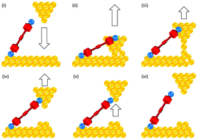
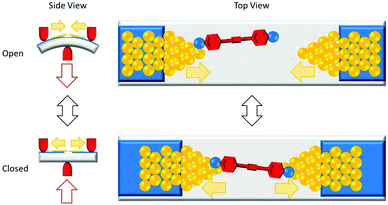
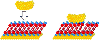
The conductance properties of molecular wires have been investigated using various methods. These are based on molecular junctions in which either single molecules or molecular assemblies are trapped between two electrodes. Single-molecule studies are the more common approach for OAEs, but numerous ensemble studies have also been reported, as will be seen below. Single-molecule conductance approaches include the scanning tunnelling microscopy break-junction method (STM-BJ),14 summarised in Fig. 2, and the mechanically controlled break junction (MCBJ)15 technique, summarised in Fig. 3. Ensemble studies of molecular assemblies, such as self-assembled monolayers (SAMs), can be carried out using techniques including conductive probe atomic force microscopy (c-AFM),16 summarised in Fig. 4, and eutectic gallium-indium (EGaIn) electrode based methods,17 summarised in Fig. 5. These and other methods have been thoroughly described in many reviews,18–26 so will not be subject to detailed discussion here. Some aspects of their development are discussed in section 1.3. Thermal properties of molecular wires can be determined using modifications to these and other methods.27–30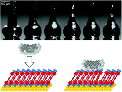 | ||
| Fig. 5 Above: Sequential images showing formation of an EGaIn tip by withdrawal of a syringe needle filled with EGaIn from a drop of EGaIn on a silver surface. This figure has been reproduced from ref. 17 with permission from Wiley-VCH, copyright 2008. Below: Cartoon of an EGaIn tip contacting a SAM of molecules of interest on a Au surface. Lighter grey spheres represent the Ga2O3 oxide layer that coats the EGaIn (darker grey spheres). The large area of the tip relative to a molecule means multiple molecules bridge the surface-tip gap and contribute to junction conductance. | ||
Molecular junctions are widely investigated using computational methods. Charge transport simulations using molecular orbitals derived from density functional theory (DFT) or Hückel (tight-binding) theory are used to calculate transmission functions for molecular junctions.25,31 A transmission function shows how the transmission coefficient T(E) of a molecular junction varies with its energy E, usually considered relative to the system's Fermi energy (EF). It represents the probability that an electron of energy E will pass across a junction from one electrode to the other, through the molecule. T(E) is proportional to conductance, G. In a typical molecular junction study, at low bias and in the absence of external influences such as gating, the energy of interest is usually close to EF. However, a disadvantage of charge transport simulations is that they often fail to provide accurate values of EF.31,32 This can be mitigated through methods such as spectral adjustment,32 where energy levels are modified based on empirical data. Another source of discrepancy between theoretical and experimental studies is that charge transport simulations generally consider a single optimised junction geometry, whereas the geometry of an experimental junction is largely unknown, cannot be precisely controlled, and in the case of break junctions varies for each individual conductance trace. Nevertheless, at least qualitative agreement is usually seen with experimental conductance studies.25
Fig. 6 shows a representation of two typical transmission functions. Important features include resonances coincident with the highest occupied molecular orbital (HOMO) and lowest unoccupied molecular orbital (LUMO) of the molecule, which appear as Lorentzian peaks with maxima where T(E) = 1. EF lies in the region between these peaks, the HOMO–LUMO gap. The orbital closest to EF is most influential on the properties of the junction.33 Transmission functions contain features relating to quantum interference (QI) effects (see section 3.2). In most cases a smooth, featureless curve between the HOMO and LUMO peaks is indicative of constructive QI (CQI) (blue solid curve, Fig. 6). Destructive QI (DQI) is associated with sharp antiresonances where T(E) approaches 0 (red dashed curve, Fig. 6). In simple systems these features occur close to EF and result in low low-bias conductance. Certain structural features can cause antiresonances to be shifted away from EF and thereby reduce their impact on conductance.34–36
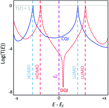 | ||
| Fig. 6 Illustration of representative transmission functions of molecules exhibiting CQI (blue solid curve) and DQI (red dashed curve) on an arbitrary energy scale. Molecular orbital energies for each molecule are indicated using dashed lines in a matching colour, with the Fermi energy (EF) shown in pink. This figure has been adapted from ref. 34 with permission from The Royal Society of Chemistry, copyright 2021. | ||
1.3 A history of OAEs in molecular electronics
In the 1990s, before the technology to measure the conductance of molecules in junctions was developed, Tour and colleagues advocated OAEs as ideal candidates for conjugated molecular wires, and extensively described their synthesis and assembly on surfaces.37–43The earliest example of an OAE wire (indeed, any conjugated molecular wire) in a molecular junction was presented in the 1996 work of Bumm et al.,44 entitled “Are single molecular wires conducting?” The OPE3 molecule 1 (Fig. 7), prepared in Tour's group,37 was embedded within a SAM of n-dodecanethiol on a Au(111) surface. An STM was used to locate molecules of 1 within the SAM and to show that the conductance of 1 appeared qualitatively higher than the surrounding n-dodecanethiol, despite 1 being a longer molecule. Subsequently, an approach was developed in which the application of voltage pulses allowed patterning of OPE wires within an n-dodecanethiol matrix.45
After establishing that conjugated OAE-type molecular wires were, as expected, more conductive than saturated alkanethiols, molecular conductance was probed in a quantitative manner. Methods used to achieve this can be broadly divided into those based on nanoscale molecular junctions containing individual molecules, and those based on larger molecular junctions containing many molecules. Single-molecule methods mostly rely on repeated junction formation, measurement and breaking in order to acquire statistically significant data sets, usually comprising hundreds or thousands of individual conductance traces.46 Advances in methodology mean this process can now largely be automated. In the vast majority of cases single-molecule measurements use Au–molecule–Au junctions. Ensemble approaches measure many molecules simultaneously and permit easier variability of electrode materials. However, determining “per molecule” contributions is not straightforward, which can complicate quantitative comparisons between studies or dissimilar molecules.
c-AFM was developed to study the dielectric properties of SiO2 films in the early 1990s,53 but was later applied to molecular conductance studies. By the early 21st century c-AFM had been used to investigate the conductance of alkanethiols16,54 and conjugated molecules,54 including OAEs.55 By using mixed monolayers in some cases a single-molecule junction can be created in a cAFM experiment.55 Single-component SAMs are more common for OAEs; here the number of molecules in a c-AFM junction can vary from tens to hundreds. Ideally, the same AFM tip and force are used for a series of related molecules to ensure a similar contact area between the tip and the molecular assembly. Assuming the molecules assemble with similar density, the number of molecules contacted should be similar across the series,56 allowing valid comparisons to be made. To compare dissimilar molecules, the Hertz model57–59 can be used to approximate the contact area of the c-AFM junction. In conjunction with methods to determine molecular area, such as reductive desorption, the conductance per molecule can then be estimated.60 While break junction methods rely on identical electrode materials, c-AFM can investigate asymmetric junctions, for example by contacting assemblies of molecules on gold using AFM tips made of (or coated with) Ag,56 Pt56,60 or graphene.60 As the tip is pushed into contact with the SAM, specific anchoring groups are not necessary at the top contact.
The EGaIn method (Fig. 5) was first reported by Chiechi et al. in 2007.17 It has several advantages over the similar, older Hg-drop electrode method,21,61 not least the avoidance of toxic mercury which can form undesired amalgams with other metallic electrodes.17 EGaIn is a room temperature liquid metal from which a sharp tip can be formed by pulling a syringe of EGaIn away from a drop (Fig. 5). The tip retains its shape due to a surface layer of Ga2O3, which imparts the liquid with non-Newtonian properties.21 It can conform to a SAM surface upon contact. An EGaIn junction is therefore of the form: bottom electrode-SAM-Ga2O3-EGaIn, where the bottom electrode can be e.g. Au,62 Ag17 or Pt.63 The tip diameter is largely defined by the properties of EGaIn, meaning it is consistently ca. 25 μm.21 Interactions between the SAM and Ga2O3 layer are generally non-covalent, meaning that molecules do not necessarily require an anchoring group to interact with the top contact. As for c-AFM, it is possible to estimate the effective contact area of the EGaIn electrode to facilitate comparison with other methods.64 The conductance of an OAE was investigated using EGaIn in 2011,65 and data for a series of OPEs were presented in 2016.62 Subsequent studies examined more complex OAEs.63,66–69
An older method for determining ensemble conductance that is rare in recent literature is a crossed-wire junction.70 A SAM assembled on a Au wire is contacted by a second perpendicular Au wire, forming a junction containing ca. 1000 molecules. Early examples of this technique used OPE3s, amongst other molecules.70
A third family of conductance studies are those based on nanogaps. The approaches used are much more variable between research groups than e.g. break junction studies. In general, they rely on the fabrication of devices in which two electrodes are separated by a nanoscale distance. Electrode materials can include gold,71 silicon,72 graphene73–75 and carbon nanotubes (CNTs).76,77 When exposed to a solution of a molecular wire of suitable length, it is possible for the gap to be bridged by one or more molecules which bind to both sides. The electronic properties of the junction can then be investigated. While the number of bridging molecules can vary between devices and depend on the nature of the nanogap, it is possible to achieve junctions containing a single molecule.73 However, the yield of suitable junctions is frequently low,71,73 prohibiting the collection of large data sets common to break junction methods.
Molecular junctions are not the only method by which charge transport along a molecular backbone can be investigated.78 OAE derivatives also find use as bridging units between functional groups in donor–bridge–acceptor (D–B–A) systems,79–81 mixed valence complexes82,83 and biradical systems.84 Such studies are outside the scope of this review.
Ensemble approaches can also be used to analyse the thermal properties of molecules. Using c-AFM it is possible to simultaneously measure electrical conductance and thermopower.90 Measurement of thermopower using an EGaIn electrode was reported in 2018.91 Notably, the Seebeck coefficient of a molecular junction is independent of the number of molecules present.28 This means that unlike studies of electrical conductance, comparisons can be made between materials and methods without needing to estimate the number of molecules present in an ensemble junction. Thermal conductance measurements of SAMs are possible, but so far are largely limited to alkane species.27
1.4 Why use OAEs for molecular electronics?
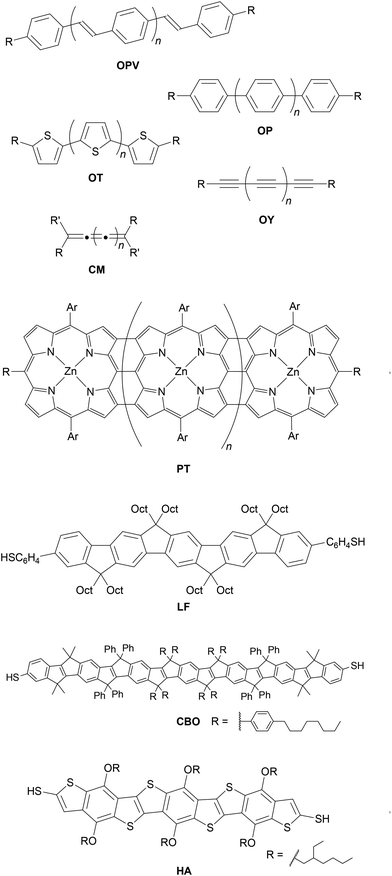
As the field of molecular electronics has developed, many different conductive conjugated backbones have been utilised in molecular wires. These include oligo(arylene vinylene)s92 (most commonly oligo(phenylene vinylene) (OPV)93–95), oligoarylenes96 (including oligophenylenes (OP)33,54,97,98 and oligothiophenes (OT)99–101), oligoynes (OY),102,103 cumulenes (CM)104 and porphyrin tapes (PT),105 for which generic examples are shown in Fig. 8. Various ladder compounds have also been used as backbones; Fig. 8 shows representative examples of a ladder fluorene (LF),106 carbon-bridged OPV (CBO),71 and heteroacene (HA).107 Nevertheless, OAEs continue to attract considerable attention. In particular, OPE3-dithiol (Fig. 1b, n = 1, R = SH) has been described as ‘a “fruit fly” molecule for detailed single-molecule transport studies’.108 Some key advantages of OAEs relative to alternative backbones include:• Rigidity. OAEs are inflexible and length-persistent due to the sp-hybridised carbons within the alkyne units (unless multiple non-para-connectivities are present). While OPVs have been shown to be more conductive than OPEs,93 the possibility for isomerisation about alkene bonds means significant conductance variation is observed for OPVs.94 The possibility of aryl–aryl bond rotation means that oligothiophenes are not length-persistent; this isomerism has also been shown to affect conductance.100
• Stability. Oligoynes and cumulenes are rigid systems but beyond relatively short molecular lengths they are unstable in the absence of significant steric shielding.102,104 OAEs benefit from the rigidity of alkyne bonds but do not suffer from the same stability concerns.
• Synthetic accessibility and variability. Other rigid, stable backbones such as ladder compounds,71,106,107 butadiynyl-linked porphyrins109 and porphyrin tapes105 exhibit favourable conductance properties. However, their widespread uptake is hindered by synthetic challenges. In contrast, protocols for the preparation of OAE wires are well-established, typically high-yielding, and readily allow the incorporation of diverse functionality, as discussed in section 2.
• Minimal steric strain. Oligophenylene wires are rigid, stable and readily synthesised, but their backbones are necessarily twisted due to steric strain between consecutive rings. Conductance has been shown to be a function of the dihedral angle between adjoining rings, and is highest for coplanar systems.110 The presence of an ethynyl unit between each aryl ring in OAEs means that all the aryl rings can be near-coplanar, although there is a low barrier to rotation of the aryl rings.111 OAE wires are, therefore, more favourable than oligophenylenes. While not necessarily representative of junction configurations, X-ray crystal structures of OAEs of different lengths show that near-coplanarity of aryl rings is often favoured in the solid state.112
• Magnitude of conductance. OAEs are experimentally convenient as the conductance of molecules from OAE2 to OAE5 and beyond generally lies within the window accessible to common measurement techniques. At shorter lengths, up to ca. OAE3, species where conductance is reduced, for example due to QI, are also often within the experimentally accessible range. This means that series of OAEs can provide insightful studies of structure–property relationships and QI effects. Many of these studies are discussed in section 3.
2 Structure and synthesis of OAEs for molecular junctions
This section will summarise some key synthetic methods used to prepare OAE molecular wires then highlight the structural variations possible within the OAE framework.2.1 Synthetic methods
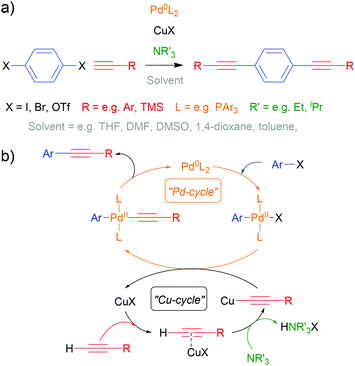
The Sonogashira cross-coupling reaction113,114 has been fundamental to OAE synthesis since the early days of the field.40 Indeed, a detailed review from 2011 remains highly relevant.115 An example of OAE synthesis using the Sonogashira coupling is shown in Scheme 1a and a general catalytic cycle is shown in Scheme 1b. It should be noted that uncertainty remains over the exact nature of the Cu-catalysed cycle.113–115 A palladium- and copper-catalysed reaction takes place between an aryl halide (or pseudohalide such as triflate, –OTf, or diazonium salt, –N2X), Ar–X, and a terminal alkyne, H–C![[triple bond, length as m-dash]](https://www.rsc.org/images/entities/char_e002.gif) C–R, in which a C–C bond is formed between the (pseudo)halide-bearing sp2 carbon of the aryl unit and the proton-bearing sp carbon of the acetylene, forming Ar–C
C–R, in which a C–C bond is formed between the (pseudo)halide-bearing sp2 carbon of the aryl unit and the proton-bearing sp carbon of the acetylene, forming Ar–C![[triple bond, length as m-dash]](https://www.rsc.org/images/entities/char_e002.gif) C–R with effective loss of HX. Iodides are the most reactive halide, although triflates and bromides suffice in many cases. Mixed-halide precursors can be used chemoselectively in the synthesis of asymmetric systems.115 The presence of electron withdrawing groups on the aryl halide also enhances reactivity.115
C–R with effective loss of HX. Iodides are the most reactive halide, although triflates and bromides suffice in many cases. Mixed-halide precursors can be used chemoselectively in the synthesis of asymmetric systems.115 The presence of electron withdrawing groups on the aryl halide also enhances reactivity.115
Extensive early synthetic work by the Tour group on long OAEs utilised solid-supported synthesis.40 This method typically afforded a series of compounds with doubling lengths, e.g. OAE2, OAE4, OAE8, OAE16. Solid-supported approaches are rare in more recent literature, in which shorter OAEs are usually preferred in order to achieve experimentally-detectable conductances. For this reason smaller length differentials are usually desirable: the conductance of an OAE2, OAE3, OAE4 series is much less challenging to determine experimentally than that of an OAE2, OAE4, OAE8 series. For the typical length range of OAEs, at least at research laboratory scale, solution-based synthesis is currently favoured.
The broad availability of suitable aryl halide precursors and monoprotected alkynes such as trimethylsilylacetylene (TMSA) means that many OAE backbones can be readily synthesised in a stepwise fashion. For example, an OAE3 system can be prepared from a dihalogenated arene by first performing a twofold Sonogashira coupling with TMSA to afford a protected diyne (Scheme 1a, R = TMS). After deprotection, another twofold Sonogashira coupling with a halogenated anchoring group would afford an OAE3. Alternatively, the halogenated anchoring group could be functionalised with TMSA, deprotected and then coupled to the dihaloarene (Scheme 1a, R = anchoring group). Alternative methods115 to prepare alkyne precursors include the Corey–Fuchs synthesis, which requires an aldehyde precursor; however, this protocol is rarely utilised in the preparation of OAE wires for molecular junctions.
Not all key building blocks for OAE wires are available commercially. The functionalisation or construction of more complex polycyclic systems can often be necessary prior to their use in Sonogashira couplings, and can require many synthetic steps.66,116,117 This can be particularly relevant for connectivity in unreactive positions, even for simple monocyclic species.118
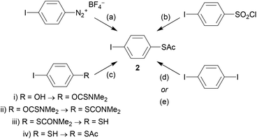
As an example, the key building block 4-(acetylthio)iodobenzene (2) will be considered. Although acetyl-protected thiols are arguably the most popular anchoring unit for OAE wires, 2 is not widely available commercially. However, it can be prepared from various precursor molecules. Scheme 2 shows the following synthetic protocols for 2: (a) nucleophilic substitution of a diazonium salt119 (prepared from 4-iodoaniline, not shown), (b) reduction and protection of 4-iodobenzenesulfonyl chloride,120 (c) a multi-step transformation of 4-iodophenol,121 and monosubstitution of 1,4-diiodobenzene using either (d) butyllithium42 or (e) copper catalysis.60,122 To our knowledge, the diazonium route was the first reported synthesis of 2, but it is not frequently used. The reduction method is more widespread and reportedly high-yielding. This route and the multi-step route from 4-iodophenol are both described as more reliable than selective monolithiation.120,121 The copper-catalysed route was reported more recently.122 It relies on statistical monosubstitution, but this can be favoured by using an excess of diiodide and recycling the unreacted material.60
The relatively labile nature of the acetyl protecting group means that it is not compatible with basic reaction conditions, and consequently 2 must often be added in the final synthetic step. Where this is not possible or convenient, transprotection of other sulfur species (e.g. tert-butyl or cyanoethyl thioethers) provides an alternative.123–126 These less labile protecting groups also find use in approaches reliant on orthogonal protection. For example, cyanoethyl thioethers were used in conjunction with 2-hydroxyprop-2-yl protected alkynes in the synthesis of long OAEs, in which the polar 2-hydroxyprop-2-yl protecting group additionally facilitated purification.127 Pyridine, amine and methyl thioether (SMe) anchors have a wider tolerance of reaction conditions than thioacetates, and halogenated derivatives are readily available. These anchor groups can, therefore, be utilised earlier in a synthetic route without the need to prepare them first. This helps to rationalise the widespread use of these anchoring groups despite the often-superior properties of thiols – e.g. stronger binding to Au and higher conductance.
2.2 Structural diversity of OAEs
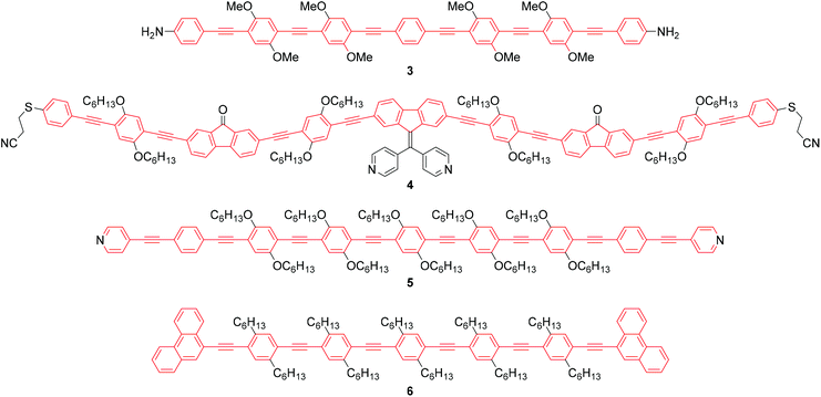
As stated above, an OAE wire can be considered to consist of two primary components: the conductive OAE backbone and its anchoring groups. Side group functionalisation of the OAE backbone is another common feature. Variation based on each of these three structural components will be discussed below. The use of OAE backbones as a means of incorporating other functionality into molecular wires will then be examined.Fig. 9 shows OAEs 3–6 which have long backbones (up to OAE9) and have been studied in molecular junctions.76,112,128,129 From a synthetic viewpoint, while the preparation of shorter OAEs is less laborious, molecular length is limited primarily by availability and solubility of precursors. Given these factors, increasingly long wires can be prepared iteratively by increasing the number of synthetic steps performed. Indeed, early work on OAE wires describes the synthesis of an OPE18,41 OAE1942 and OAE23.43 The discrepancy between the lengths of OAE available synthetically and those typically measured in junctions in part relates to the decay of conductance with molecular length (see section 3.1); the electrical conductance of very long OAEs is generally below the noise level of the equipment used to determine molecular conductance experimentally. Longer molecules are necessarily more prone to intermolecular interactions than shorter analogues, and surface interactions, through e.g. van der Waals forces, can effect molecular assembly.130 There is no clearly defined limit on the molecular length for which measurements are practical, as conductance properties are influenced by many other factors. However, most conductance studies investigate OAE5 molecules or shorter, as will be seen in the discussion below. This range coincides with OAEs which can be synthesised relatively quickly and easily.
The number of OAE repeat units is not the only factor to affect molecular wire length. Clearly, the size of arylene systems can have a significant influence (e.g. benzene vs. porphyrin, or OAE9s 4 and 5 in Fig. 9). Changes to molecular geometry exert little effect on the length of the conductance pathway through the OAE backbone in terms of the number of C–C bonds included. However, they can significantly alter the shortest through-space distance between anchoring groups and hence reduce the distance between junction electrodes.
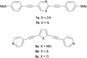
Many different aryl groups have been incorporated into conductive OAEs. The effect on electronic conductance of factors such as the connectivity, aromaticity and extent of conjugation of these aryl groups is discussed in more detail in section 3. The simplest OAE wires are unfunctionalised OPEs (Fig. 1b), with purely hydrocarbon backbones. One of the simplest modifications of an OPE to afford an OAE is the replacement of one or more benzene rings with pyridine rings. In cases where pyridine rings are terminal, they typically act as anchor groups; such systems are discussed in the section 2.2.2. Pyridine functionality can also be included elsewhere in the OAE backbone, e.g. as the central ring of an OAE3 in 7a, Fig. 10.131 QI effects have been studied by varying the location of the nitrogen atom of a central, meta-disubstituted pyridine in a series of OAE3s,132 see section 3.4.
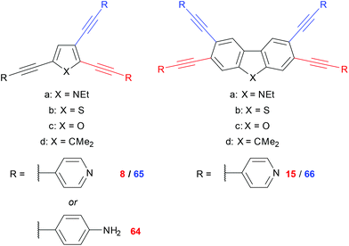
Other simple heterocycles are also readily incorporated into OAEs as either terminal or proximal aryl units. In some cases, terminal heterocycles can be used directly as anchoring units (see section 2.2.2). Examples of heterocycles which have been used as proximal aryl units include pyrrole, thiophene, furan and selenophene (e.g.8a–c, Fig. 10).118,131,133,134 Note that the inclusion of 5-membered heterocycles results in more angular molecular wires compared to linear para-linked OPEs. Incorporation of heterocycles can have undesired effects: 7b (Fig. 10), an OAE3 with a central pyrimidine ring, was observed to display two distinct conductance features in STM-BJ experiments. One was assigned to conventional terminal anchoring, the second was attributed to additional anchoring interactions with the pyrimidine ring.131
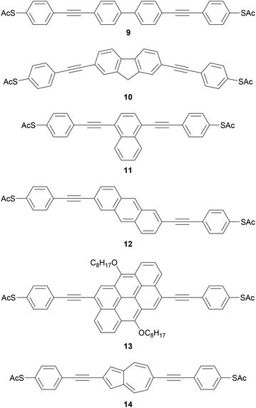
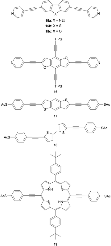
Polycyclic systems have been widely studied, particularly as the central units of symmetric OAEs. Purely hydrocarbon units include biphenyl (9),68,135–137 fluorene (10),68,135–138 naphthalene (11),125,136 anthracene (12),125,136,139 anthanthrene (13)117,140 and azulene (14);141 example structures are shown in Fig. 11. Heterocyclic derivatives include carbazole (15a),137 dibenzothiophene (15b),137 dibenzofuran (15c),137 benzodifuran (16),142,143 benzodithiophene (17),66 bithiophene (18),68 and (metallo–)porphyrins (19);144–146 example structures are shown in Fig. 12.
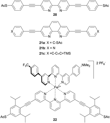
OAEs containing ligating heterocyclic moieties such as bipyridine (20),147 phenanthroline (21)148 and terpyridine (22)149 have been used to investigate the effects of metal complexation on molecular conductance (Fig. 13). The conductance of 20 was shown to increase upon coordination to Pd.147 Switching of 21 upon Cu-complexation was anchor group dependent,148 as discussed in section 3.6. An OAE with a central terpyridine unit formed the iron complex 22, which exhibited bistable junction properties dependent on an applied electric field. This behaviour was attributed to a change in the spin state of the iron ion, from low- to high-spin. This spin crossover is caused by distortion of the octahedral coordination sphere of Fe2+ upon alignment of the dipole of the asymmetric second ligand with the applied field above a critical voltage.149 Notably, the use of an OAE architecture with isopropyl shielding groups significantly increased the proportion of junctions which displayed bistability compared to an unshielded oligoarylene analogue. This was related to a reduced potential for interaction between the functional subunit and the electrodes brought about by the increased distance from the electrodes and steric shielding.149
The molecular geometry of an OAE provides another source of structural variation. In the simplest example, difunctionalised benzene (or other 6-membered) rings can have ortho-, meta- or para-substitution. Early studies suggested that the single-molecule conductance of o-benzenedithiol (and o-phenylenediamine) could not be measured, and that the two anchor groups preferentially bind to the same electrode due to their close proximity.150 Subsequent developments in break-junction technology have allowed the conductance of o-benzenedithiol to be measured, albeit with low junction formation probability (<10%).151 While for benzenedithiol isomers the length of the conductance pathway increases such that ortho < meta < para, the conductance is predicted to follow the trend ortho > para > meta due to QI effects (see section 3.2), which was indeed observed experimentally.151
Fig. 14 illustrates the same o/m/p-isomerism at the central ring of generic OPE3s (o-, m- and p-OPE3). Like o-benzenedithiol, the anchoring groups of o-OPE3 are positioned such that they can more easily bind to the same electrode than to two different electrodes. This straightforward structural observation means that despite favourable QI properties, ortho-linked OAEs are not prevalent in molecular junction studies. The rigid nature of alkyne bonds means that m-OPE3 and p-OPE3 can both easily bridge between two electrodes, and indeed many such species have been investigated in molecular junctions.132,152,153
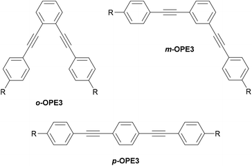 | ||
| Fig. 14 Structural isomers of a generic OPE3 differing in their substitution pattern on the central ring. R denotes an anchoring group. | ||
The location of the anchoring groups can be varied in a similar manner. The importance of this effect was shown experimentally in 2003 by comparing the OAE3 wires m-23 and p-23 (Fig. 15), which differ only in the connectivity of their anchoring groups relative to the OAE.154p-23 was found to be significantly more conductive than m-23.
More recently, Manrique et al. investigated a series of OAE3s with ortho-, meta- or para-pyridyl anchoring groups (relative to the backbone alkynes) and either para- or meta-connectivity at the central ring (x,y,z-24 in Fig. 15, where the preceding letters x, y and z indicate o-, m- or p-geometry in the order anchor group, central ring, anchor group, i.e. left-to-right as drawn).155 Their results also showed that para-connected anchoring groups afforded higher conductances than their meta-isomers. Similarly to benzenedithiol isomers, ortho-connected anchoring groups were found to have low junction formation probability (attributed to steric effects), but higher conductance than their meta-isomers; indeed p,p,p-24 and o,p,o-24 had the same conductance in STM-BJ measurements, an order of magnitude higher than m,p,m-24.155 A further disadvantage of ortho-anchoring was seen in the case of o,m,o-24, for which no conductance feature was observed. This was attributed to a combination of the short distance between the anchoring nitrogen atoms and a low expected conductance, which meant that any molecular conductance features were overlaid by the direct Au–Au tunnelling current.155 The study also showed that para-connectivity at the central ring affords higher conductance than meta-connectivity;155p,p,p-24, m,p,m-24 and o,p,o-24 were all at least an order of magnitude more conductive than their respective analogues, p,m,p-24, m,m,m-24 and o,m,o-24. Similar results have been consistently observed for OAE3 species with a range of anchoring groups.132,152,156,157 While para-connectivity is clearly advantageous in terms of electronic conductance, meta-linked species have favourable thermal properties.152 This will be discussed in more detail in section 4.2.
Geometric variation is not limited to ortho-, meta- and para-isomers of 6-membered rings. Many of the heterocyclic and polycyclic aryl units discussed above (e.g.Fig. 11 and 12) have been investigated in connectivity comparisons.117,118,125,126,137,138 However, it should be noted that as the complexity of the aryl unit increases it becomes less likely that all possible isomers can be easily synthesised, or indeed synthesised at all. The effects of varying connectivity in polycyclic and heterocyclic systems are discussed in detail in sections 3.2 and 3.4, respectively.
| Structure and name (abbreviation) | Anchoring mode to typical surface | Literature examples (Ref. no.) |
|---|---|---|
| a During the extension of a break-junction, π-Au anchoring interactions can also occur.162 | ||

|
Covalent (S–Au), loss of H+ | 15 and 48 |

|
Covalent (S–Au), loss of Ac+ | 160–163 |

|
Dative (N → Au)a | 160–162 |

|
Dative (N → Au) | 160–162 |

|
Dative (S → Au) | 161, 164 |

|
Dative (S → Au) | 102, 157, 162 and 164 |
|
Dative (S → Au) | 165 and 166 |

|
Dative (S → Au) | 156 and 167 |

|
Dative (Se → Au) | 164 |

|
Dative (N → Au) | 160, 162 and 163 |

|
Dative (O → Au) | 163 |

|
Dative (C → Au) | 168 and 169 |

|
e− donation from Au (Au → Si) | 170 and 171 |

|
Covalent (C–Au), in situ removal of SiR′3+ | 142, 172 and 173 |

|
Covalent (C–Au), loss of H+ | 174 and 175 |

|
Covalent (Ar–Au), loss of N2 | 122 |

|
Covalent (S–Au), mono- or bidentate, in situ removal of TMS–CH2CH2+ | 143, 145 and 176 |

|
Covalent (N–Au), loss of H+ | 177 |

|
Dative (N → Au) | 178 |
|
Covalent (S–Au × 3) | 179–181 |
|
π-Interaction (π-Au) | 182 |
|
Dative (S → Au × 4) and π-Au | 60 |
|
Dative (N → Au and S → Au × 2) | 183 |

|
Dative (N → Au and N → Au) | 184 and 185 |
|
π-Interaction (π-Au) | 186 |

|
π-Interaction (π–πCNT) | 76 and 77 |
|
π-Interaction (π–πGraphene) | 73–75 |
|
π-Interaction (π–πGraphene) | 73 |

|
H-Bond (COOH and ITO surface) | 165 |

|
H-Bond (C![[double bond, length as m-dash]](https://www.rsc.org/images/entities/char_e001.gif) O and ITO surface) O and ITO surface) |
165 |
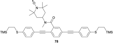
The most widely used anchoring groups for metal-molecule-metal (generally Au–molecule–Au) junctions are thiol (–SH), pyridine (–C5H4N) and amine (–NH2) groups.160,161 These functionalities are usually easy to incorporate into an OAE structure and they afford sufficiently stable and reproducible junctions for conductance studies.161 While pyridine- and amine-bearing species can be assembled directly on surfaces, thiol assemblies are usually prepared from a protected precursor. This is because free thiols readily oxidise to form disulfides, which do not assemble efficiently and can result in polymerisation of wires bearing two thiol anchors.39 Thioacetates are archetypal masked thiols, as they can be deprotected under mild conditions to form thiolates.39,124,187 Notably, thioacetates spontaneously cleave in the presence of gold to form the direct Au–S bonds that would be expected from thiols or thiolates.39 Investigations comparing assemblies prepared via spontaneous cleavage to those formed using a deprotecting agent suggest that the optimal method depends on the proposed application.124,187 For experiments where a densely packed SAM is not required, such as single-molecule conductance studies, chemical deprotection is not necessary. However, controlled use of a suitable basic deprotecting agent can facilitate the formation of densely packed high-quality SAMs suited to ensemble studies.124 Cyanoethyl129 and trimethylsilylethyl188 protecting groups have also been used to mask thiols, although in these cases addition of deprotecting agents is necessary in order to form junctions.
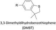
Thioether-based anchors, such as methyl thioether (methylthio, –SMe)161,164 and dihydrobenzothiophene (DHBT)102,157 derivatives have seen increasing use in recent years as they allow for strong Au–S interactions (albeit weaker than those between thiols and gold161), can assemble directly on surfaces, and have wider chemical compatibility during synthesis than protected thiols. An important difference between –SMe and –SAc anchoring groups is that the methyl group is retained upon binding to a gold surface whereas the acetate group is not; the lower conductance of thioethers relative to thiols is attributed to this phenomenon.161 The dimethylated analogue of DHBT, namely DMBT, is also an effective anchor for gold surfaces.165,166 Thiophene has been used as a sulfur-based anchor, usually as a 3-thienyl (–C4H3S) substituent.156,167 Selenium-based anchoring groups, for example methyl selenoether (methylseleno, –SeMe), have been shown to have similar properties to their sulfur analogues.164 Their lack of widespread use is therefore not surprising, given the lower availability and increased cost of precursor molecules compared to sulfur species and the foul smell of many organoselenium compounds.
Other simple functional groups which have been utilised for anchoring include cyano- (nitrile, –CN),160,163 nitro- (–NO2)163 and isocyano- (isonitrile, –NC)168 moieties. These do not anchor as effectively or reliably as the species discussed above, and so are less commonly used. For example, isocyano-anchored OPEs were observed to desorb from gold surfaces upon exposure to air through decomposition to isocyanates.169 Carboxylic acid functionalised OPEs have been assembled in Langmuir–Blodgett (LB) films, transferred onto gold surfaces and captured in molecular junctions using an STM.189 Recent results show that a pyridinium ring can be an effective anchor in the presence of an external electric field.190
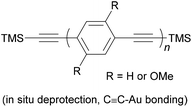
Trialkylsilylethynyl groups are often present in intermediates used in the preparation of OAEs (see section 2.1). They have also been applied to anchoring in two different ways. Trimethylsilylethynyl (TMSE) groups can bind with a gold surface through the silicon atom. This is attributed to a switch from a tetrahedral to a trigonal bipyramidal geometry upon electron donation from the gold surface.170 The resulting molecular junctions give well-defined conductance features, attributed to the steric bulk of the TMS group, although conductance is lower than for common anchoring groups.170,171 In an alternative approach, in situ treatment of TMSE172 or triisopropylsilylethynyl (TIPSE)142,173 terminated OAEs with tetrabutylammonium fluoride (TBAF) allows for assembly of molecular wires on metallic surfaces through direct alkyne–metal bonds, i.e. R–C![[triple bond, length as m-dash]](https://www.rsc.org/images/entities/char_e002.gif) C–Au. The single-molecule conductance of such junctions was shown to be higher than that of comparable thiol-anchored species.172 However, within 1 h surface-mediated oxidative dimerization of the deprotected species results in the formation of oligomers, which can also be captured in junctions, complicating data analysis.172 Direct alkyne binding has been applied to functionalisation of Au, Pt, Pd, Rh, Ir and highly ordered pyrolytic graphite (HOPG) surfaces, although rehybridisation of the atoms involved in bonding may occur in some cases.191 Switching between pyridyl and alkyne anchoring during the course of a MCBJ experiment has been achieved using 16 (Fig. 12) though in situ deprotection of the TIPSE units.142
C–Au. The single-molecule conductance of such junctions was shown to be higher than that of comparable thiol-anchored species.172 However, within 1 h surface-mediated oxidative dimerization of the deprotected species results in the formation of oligomers, which can also be captured in junctions, complicating data analysis.172 Direct alkyne binding has been applied to functionalisation of Au, Pt, Pd, Rh, Ir and highly ordered pyrolytic graphite (HOPG) surfaces, although rehybridisation of the atoms involved in bonding may occur in some cases.191 Switching between pyridyl and alkyne anchoring during the course of a MCBJ experiment has been achieved using 16 (Fig. 12) though in situ deprotection of the TIPSE units.142
Assembly of alkynes on gold has also been described using hydrogen-terminated alkynes as the anchoring group precursor, with formation of R–C![[triple bond, length as m-dash]](https://www.rsc.org/images/entities/char_e002.gif) C–Au linkages.174,175 The reported assembly conditions usually specify an inert atmosphere to prevent oxidation of the alkyne functionality, and an overnight assembly period, indicating that this method is slower and more sensitive than those based on in situ deprotection. Au–molecule–Au junctions have additionally been formed from assemblies of OAE or OAE-like molecules bearing a terminal alkyne–Au complex.192,193 After self-assembly or LB film transfer onto a gold substrate (using a conventional anchoring group), thermally-induced decomposition of the Au complex results in the loss of ancillary ligands, a reduction from Au(I) to Au(0) and the formation of Au nanoparticles (NPs) on top of the molecular monolayer. The conductance of the resulting Au–[molecule]x–AuNP junctions, containing one or more molecular wires, can be investigated by contacting the NPs with a c-AFM tip. Another method to form a direct C–Au bond relies on the use of aryldiazonium salts, which can be electrochemically grafted to gold surfaces with loss of N2, forming a direct Ar–Au bond.122
C–Au linkages.174,175 The reported assembly conditions usually specify an inert atmosphere to prevent oxidation of the alkyne functionality, and an overnight assembly period, indicating that this method is slower and more sensitive than those based on in situ deprotection. Au–molecule–Au junctions have additionally been formed from assemblies of OAE or OAE-like molecules bearing a terminal alkyne–Au complex.192,193 After self-assembly or LB film transfer onto a gold substrate (using a conventional anchoring group), thermally-induced decomposition of the Au complex results in the loss of ancillary ligands, a reduction from Au(I) to Au(0) and the formation of Au nanoparticles (NPs) on top of the molecular monolayer. The conductance of the resulting Au–[molecule]x–AuNP junctions, containing one or more molecular wires, can be investigated by contacting the NPs with a c-AFM tip. Another method to form a direct C–Au bond relies on the use of aryldiazonium salts, which can be electrochemically grafted to gold surfaces with loss of N2, forming a direct Ar–Au bond.122
The carbodithioate (–CS2−) moiety has been shown to anchor effectively to gold surfaces and afford an order of magnitude increase in single-molecule conductance versus equivalent thiols for several different conductive backbones.143,145,176 The molecules used in these studies are prepared as their 2-(trimethylsilyl)ethyl carbodithioate esters, which can be deprotected in situ with TBAF. The limited uptake of this promising anchoring group may relate to the poor availability of a key precursor material, (2-bromoethyl)trimethylsilane. Mono- and bidentate binding modes were observed in the same STM-BJ study of a symmetric OAE3 wire with carbodithioate anchors, with different conductance features assigned to junctions in which both, one, or neither of the anchoring groups bound in bidentate fashion.145 Dithiafulvene (DTF) derivatives have also been investigated as anchors with multiple sulfur contact points. They functioned more reliably in ensemble than in single-molecule junctions, but studies are limited and the precise nature of the anchoring remains unclear.194,195
Two distinct anchoring modes have also been observed when pyrazole is used as a terminal group.177 As a break junction containing a pyrazole-anchored OAE3 was stretched, the molecular conductance increased prior to breaking of the junction. This was attributed to a switch from a monodentate, dative interaction between the pyridine-like nitrogen and the STM tip to a bidentate covalent interaction following loss of the proton from the pyrrole-like nitrogen.177 Oxadiazole is another small heterocycle that has been applied as an anchoring unit, again with evidence to support different binding conformations.178
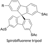
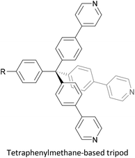
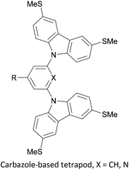
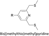
To increase the stability of molecular assemblies for molecular junctions and other applications, multipodal anchoring units incorporating several anchoring groups have been designed.196 Additional binding functionality increases the strength of molecule-surface interactions relative to a single anchoring group. The designs used to achieve this effect often have a larger molecular footprint than simple anchor groups and so occupy a higher surface area per molecule, resulting in a less dense molecular assembly; this can be useful as a means of preventing intramolecular interactions. Multipodal anchoring units that have been used in OAE wires include a spirobifluorene-based tripod,179–181 a tetraphenylmethane-based tripod182 and carbazole-based tetrapods.60 Smaller-footprint approaches using a pyridyl anchor buttressed by two (methylthio)methyl substituents,183 and a bidentate 2–aminopyridine anchor184,185 have also been reported.
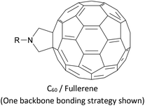
The synthesis of OAEs bearing C60 (fullerene) moieties in anchoring positions was reported in the early 2000s.197,198 Despite this, only simple disubstituted benzene (“OAE1”) systems with C60 anchors have been used to form molecular junctions,186 although C60 anchors have been utilised in larger systems with other molecular backbones,199 and C60-terminated OPE hybrids have been prepared for D–B–A studies.80
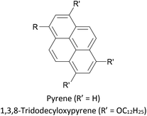
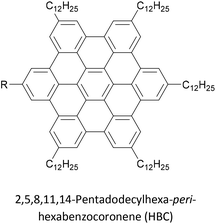
Increasing interest in junctions based on graphitic materials has led to new anchoring approaches. The extended π-system of materials such as graphene and CNTs is well suited to large, planar aromatic anchor groups, which bind through π–π interactions. These aromatic systems are readily incorporated as the terminal aryl groups of OAE-like wires. Phenanthrene-terminated OAEs and OAE-like systems such as 6 (Fig. 9) have been shown to bridge CNT nanogaps and form CNT–molecule–CNT junctions.76,776 has also been partially lifted from a Au(111) surface using an STM tip and the properties of the resulting Au–(sub-)molecule–tip junctions investigated.130 Graphene nanogaps have been bridged using porphyrin-based OAEs bearing (substituted) pyrene or alkylated hexa-peri-hexabenzocoronene (HBC) anchoring groups.73–75 Continued interest in the unique properties of graphene means that the development of additional specialised anchoring groups of this type can be expected. CNT nanogaps have also been covalently bridged by OAEs with amine anchors, which can react with carboxylic acid functionality at the CNT edge to form amides.200 A similar covalent approach based on in situ imine formation was used to bridge a silicon nanogap.72
Indium tin oxide (ITO) is a widely used electrode material in organic light emitting diodes and photovoltaics as it is both transparent and conductive. ITO–molecule–Au junctions containing asymmetric OAE2 species were recently investigated using the I(t)51 modification of the STM-BJ method.165 Carboxylic acid, 2-cyanoacrylic acid, and pyridinium squarate (PS) were all shown to be suitable anchoring groups for ITO. PS showed no affinity for Au surfaces, meaning selective junction orientation could be achieved using a species bearing both SAc and PS anchor groups.165 Selectivity studies of this type are of relevance to controlled device manufacturing, and comparable studies with other electrode materials would be insightful.
Simple alkyl or alkoxy chains are generally sufficient for solubility enhancement. In an important early study, Huber et al. first showed that the addition of two methoxy or hexyloxy substituents (25b and 25c, respectively, Fig. 16) to the central benzene ring of unsubstituted OPE3 (25a) resulted in no significant change to conductance histograms or the most probable conductance obtained via MCBJ.93 The tert-butylated analogue (25d) was later shown to have comparable conductance to 25b using the I(s) method.123 Similar results were subsequently observed for pyridine-anchored analogues with and without methoxy subsituents,112 and for a series of amine-anchored OPE3s bearing a wider range of substituents on the central ring (including alkyl, alkoxy and fluoride substituents).201 In the latter case some concentration effects were noted and attributed to differing intramolecular interactions.201 It should be noted that these studies investigated only symmetrically substituted, para-linked OAEs. In contrast, the addition of methoxy side groups to different positions on a meta-linked OPE3 substantially impacts on the molecular conductance due to QI effects,153 as discussed in section 3.4. Computational studies have demonstrated this effect for a range of electron-withdrawing and electron-donating side groups.35,36 Side group functionalisation with alkoxy chains and halides has also been found to affect thermoelectric properties,202,203 as discussed in section 4.2.
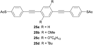 | ||
| Fig. 16 Examples of OPE3 species used to show that side groups have little effect on molecular conductance for para-connected systems. | ||
Nitro side groups were associated with negative differential resistance (NDR) in early studies of molecular junctions.204 NDR was studied in SAMs of thiol-terminated nitro-functionalised OPE3 molecules.205 It was concluded that under certain assembly conditions extensive redox reactions can occur involving oxidation of the sulfur with concomitant reduction of nitro to amine, thereby impacting the reproducibility and the analysis of the electrical properties of the assemblies.205 It is notable that nitro groups are rarely seen in more recent experimental conductance studies.
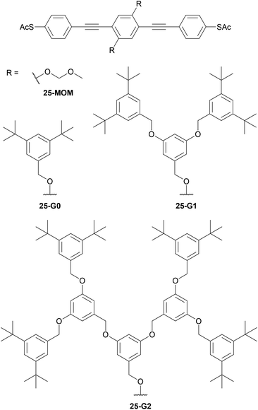
While linear alkyl chains suffice to enhance solubility, other approaches provide more extensive shielding of OAE backbones from the surrounding environment. Wang et al. studied the series of dendron-functionalised OPE3s shown in Fig. 17 in various Au–molecule–Au junctions.206 In ensemble junctions, increased dendron size was associated with lower conductance per area. This was in part accounted for by X-ray photoelectron spectroscopy (XPS) data, which showed a reduced SAM density with increasing side group size. Additional discrepancy within the series was ascribed to increased SAM disorder for the species with larger dendrons, which further reduced the number of molecules bridging the two electrodes.206 In STM-BJ experiments, reference compounds (monothiolated OPE3 and 25-MOM) afforded a conductance feature that was attributed to a π-stacked dimer. This was not observed for dendron functionalised species with bulky side groups. Conductance histograms for 25-MOM and 25-G0 contained features attributed to junctions comprising either one or two molecules, whereas that of bulkier 25-G1 displayed only the single-molecule feature.206 The implication is, therefore, that the smaller side chains are not sufficiently bulky to prevent the formation of multi-molecule junctions. The conductance histogram of 25-G2 was essentially featureless, suggesting that overly-large dendrons are not well-suited to molecular junction experiments, presumably as they can shield the anchoring functionality in addition to the backbone.206
Even more extensive shielding of an OAE backbone can be achieved by encapsulating it within a macrocycle, such as α-cyclodextrin, to form a rotaxane. Extensive synthesis of long OAEs functionalised with multiple cyclodextrin units, including control of which positions are shielded, has been reported.207 Despite this, relatively few OAE rotaxanes have been the subject of conductance studies.208–210 The OAE backbones of rotaxane species 26 and 27 (Fig. 18) are respectively encircled by one or two α-cyclodextrin macrocycles, which are attached to the OAE as side groups. In the case of 26, rotaxane shielding successfully prevented multiple molecules binding in STM-BJ experiments. It was also shown that junctions containing 26 displayed an asymmetric response to mechanical strain. Other than this, the authors state that the addition of the cyclodextrin ring had “no clear effect” on molecular conductance properties.208 In contrast, the shielding by the cyclodextrin rings in [3]rotaxane 27 was reported to afford sharp conductance features in STM-BJ experiments due to the restriction of intramolecular rotations, but features corresponding to multiple molecules in the junction were observed.210 Neither of these studies included a direct comparison with an unshielded analogue using the same STM-BJ equipment, making it difficult to confidently discern the overall effect of rotaxane shielding on molecular conductance.
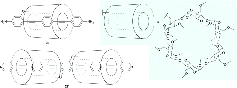 | ||
| Fig. 18 OAE wires that incorporate shielding rotaxane functionality into side groups. The structure of the shielding α-cyclodextrin macrocycle is shown on a pale blue background. | ||
DTF is an interesting functional side group that has been used by Nielsen and coworkers to produce a range of extended tetrathiafulvalene (exTTF) cruciform OPE molecular wires,56,194,195,211 exemplified by structures 28–30 in Fig. 19. (Species 30 is an example of an OPE with DTF-derived anchoring units.). exTTF cruciforms are of interest as candidate molecular redox switches. The OPE5 analogue of 28 has been investigated in a three-terminal device under gating and a magnetic field (see section 5.3 for further discussion).211 However, to our knowledge, studies of similar systems are limited to conductance measurements in the ground state. This may relate to poor reversibility in electrochemical studies.195 In c-AFM studies it was found that conductance increased as more DTF units were added to an OPE backbone.195 In contrast, in single-molecule studies (STM-BJ and MCBJ) little variation in conductance was seen for different numbers of DTF units. Furthermore, junction formation became less likely as the number of DTF units increased; this effect was attributed to the presence of increasing numbers of sulfur atoms, which could reduce the mobility of the molecular wires on gold surfaces.195 The differing trends between single-molecule and ensemble conductance measurements are believed to be due to both thioacetate protecting groups cleaving in the single-molecule studies, but only that of the surface-bound sulfur in the c-AFM experiments.195
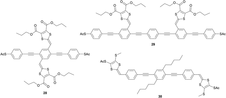 | ||
| Fig. 19 Examples of DTF-functionalised exTTF OPE wires,195 with DTF units used as side chains on the same (28) or different (29) phenylene units, or as anchoring groups (30). | ||
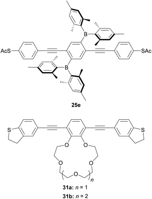
Other approaches have been used to add switching or sensing behaviour to OAE wires through side groups. Liu et al. investigated an OPE3 dithiol wire with dimesitylboryl side groups (25e, Fig. 20).212 The boron atoms can act as Lewis acids, which results in a ca. fourfold reduction in the conductance of 25e upon exposure to fluoride anions. The authors attribute this to a widening of the HOMO–LUMO gap upon fluoride binding, with support from charge transport simulations.212 The reversibility of this switching was not investigated. Cation sensing is also possible. The conductance of a DHBT-anchored OPE3 with a 15-crown-5 type side group (31a, Fig. 20) increased by a factor of up to ca. 2 upon complexation with Li+, Na+ or Rb+. The magnitude of the increase was shown to correlate with the ionic radius of the bound ion.213 A larger, ca. four-fold increase was seen upon complexation of K+. This was attributed to the formation of a 2![[thin space (1/6-em)]](https://www.rsc.org/images/entities/char_2009.gif) :
:![[thin space (1/6-em)]](https://www.rsc.org/images/entities/char_2009.gif) 1 31a
1 31a![[thin space (1/6-em)]](https://www.rsc.org/images/entities/char_2009.gif) :
:![[thin space (1/6-em)]](https://www.rsc.org/images/entities/char_2009.gif) K+ complex in which both wires bridged between the electrodes of the STM-BJ based on charge transport simulations.213 Furthermore, STM-BJ studies of 31b, with a larger 18-crown-6 type side group, for which 1
K+ complex in which both wires bridged between the electrodes of the STM-BJ based on charge transport simulations.213 Furthermore, STM-BJ studies of 31b, with a larger 18-crown-6 type side group, for which 1![[thin space (1/6-em)]](https://www.rsc.org/images/entities/char_2009.gif) :
:![[thin space (1/6-em)]](https://www.rsc.org/images/entities/char_2009.gif) 1 complexation of K+ is expected, afforded a conductance in line with the trend observed for the other alkali metal cations.213 Again, the study did not consider the reversibility of this switching. The confirmation or development of reversible ion sensors is desirable if such materials are to be applied practically in devices.
1 complexation of K+ is expected, afforded a conductance in line with the trend observed for the other alkali metal cations.213 Again, the study did not consider the reversibility of this switching. The confirmation or development of reversible ion sensors is desirable if such materials are to be applied practically in devices.
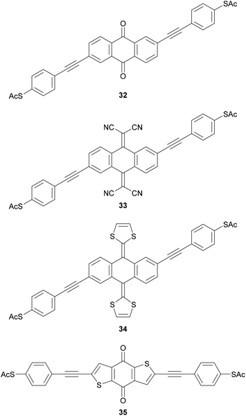
Molecular wires containing cross-conjugated quinoidal units (Fig. 21), in particular anthraquinone derivatives such as 32, are well studied. They have been used in comparisons with linearly conjugated (anthracene, e.g.12), and non-conjugated (dihydroanthracene) analogues.125,214 Comparisons have also been made with other cross-conjugated structures based on anthracene, including tetracyanoquinodimethane (TCNQ) derivatives (e.g.33) and exTTFs (e.g.34).67 These and anthraquinone wires can function as redox-switches by gaining aromaticity and becoming linearly conjugated as their oxidation state is changed,63,215–217 either electrochemically or by formation of charge-transfer salts. Quinoidal wires can also be based on other central units, such as benzodithiophene (e.g.35).66
Various other functionality has been used to impart switching behaviour into OAE derivatives (Fig. 22). Examples of redox-active switches include the tetrathiafulvalene (TTF) wire 36, although conductance studies investigated only its ground state.218 The phenothiazine wire 37 was shown to have an impressive ca. 200-fold increase in conductance upon oxidation to a radical cation with trifluoroacetic acid,219 although the reversibility of this process was not commented upon. True OAEs containing arylene units such as naphthalenediimide (NDI),220 catechol221 and benzodifuran143 have also been investigated as redox switches.
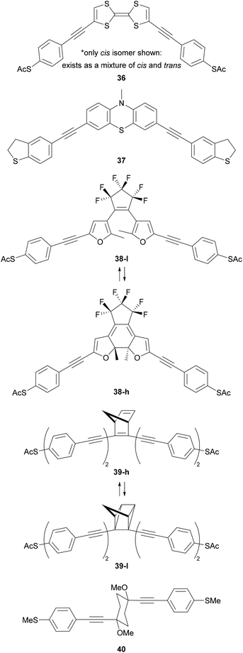 | ||
| Fig. 22 OAE-like wires with switchable central units. High (h) and low (l) conductance forms of 38 and 39 are shown. | ||
The photoswitching of diarylethenes such as 38 has been studied in both single-molecule222 and ensemble junctions.223,224 The conjugated, closed state (38-h) is around an order of magnitude more conductive than the open state (38-l).222,223 The norbornadiene-based wire 39 behaves as a memristor with two states that could be accessed by using current-induced local heating in one direction and single electron transfer in the other.225 Again, switching from a conjugated (39-h) to a non-conjugated (39-l) state reduced conductance by around an order of magnitude.225 The interconversion of conformational isomers of a cyclohexane ring in OAE3-like wires such as 40 has been detected in conductance measurements using the STM-BJ technique.226
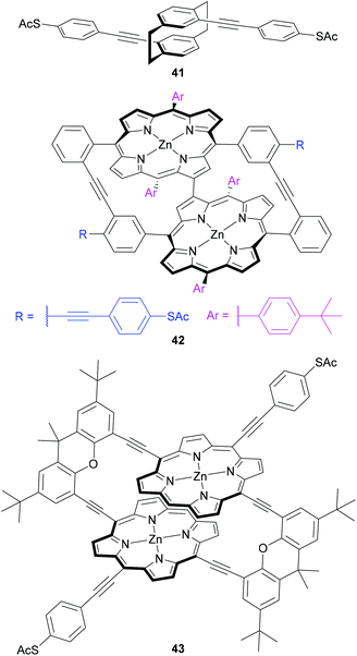
Central units have also been designed to investigate mechanical switching of OAE-like wires (Fig. 23). Mechanosensitive conductance varying over an order of magnitude was observed for a para-cyclophane centred wire (41) by carefully controlling an MCBJ.227 This behaviour was attributed to QI effects related to the energy and relative phase of the frontier orbitals in the cyclophane unit, which are sensitive to the relative position of the two overlapping benzene rings.227 Initial synthetic attempts to improve on this design using a porphyrin-based cyclophane afforded instead an unusual triply-linked bowl-shaped system (42), which was nevertheless subjected to conductance investigations.228 A change of approach gave a doubly-linked porphyrin cyclophane (43), for which initial conductance results were recently reported.116 These molecular designs are a logical progression based on similar mechanosensitivity observed in junctions containing π-stacked OPE dimers.229 The use of cyclophanes ensures the overlapping π-systems are permanently held in place covalently, rather than only through transient supramolecular interactions.
The range of switching mechanisms discussed above emphasises that switching and sensing remains a hot topic in molecular electronics. Further innovative developments of functional OAEs which are responsive to diverse stimuli are easily anticipated, and could lend themselves to applications such as logic gates.
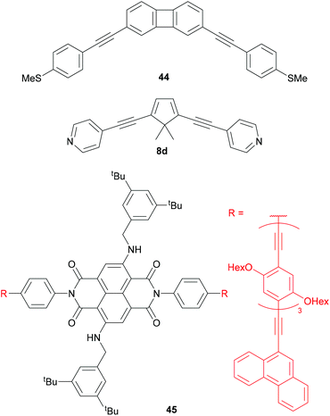
Central units in OAE-like wires have been selected for various other properties (Fig. 24). Biphenylene136 (e.g.44) and dibenzopentalene230 have served to investigate the effect of antiaromaticity on molecular conductance (see section 3.5). Cyclopentadiene (e.g.8d) has been used for comparison with 5-membered heterocycles 8a-c (see Fig. 10 and section 3.4).118,133 The photophysical properties of NDI derivatives have been utilised in molecular wire 45, which has broken conjugation. 45 is electroluminescent in a CNT-molecule-CNT junction architecture.77
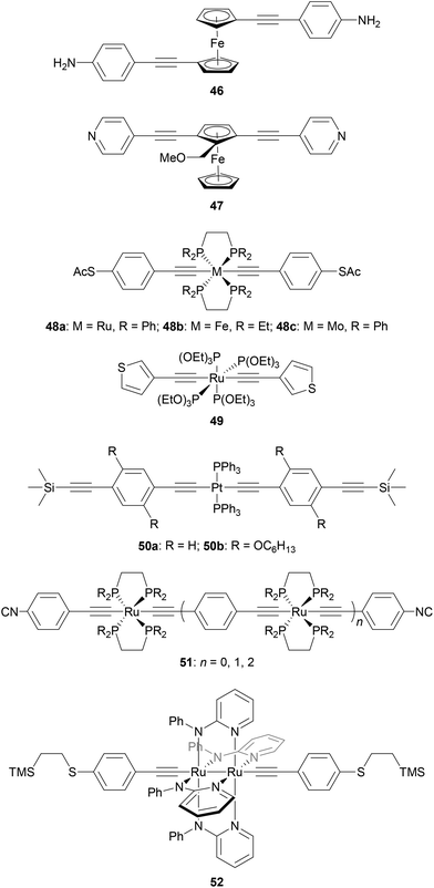
Fig. 25 shows several OAE and OAE-like wires including organometallic functionality. Wire 46 and analogues with longer and shorter OAE units were used to show that the incorporation of ferrocene units into the backbone enhanced conductance relative to analogous OPEs.232 True OAEs, where one of the cyclopentadienyl ligands of a ferrocene moiety acts as an arylene unit in the OAE backbone, such as 47, have also been studied,233 but a direct comparison with species resembling 46 does not yet appear to have been made.
Many metal bis(acetylide) complexes have been investigated in molecular junctions.231 Ruthenium and platinum complexes (e.g.48a, 49, 50) are most widely-studied but other metals such as iron and molybdenum have also been used (e.g.48b and 48c).231,234 Attractive properties of metal bis(acetylide) complexes include the possibility to finely tune molecular orbital energies through choice of metal and ancillary ligand, and opportunities to explore easily accessible redox states associated with transition metal centres.231 Conjugation is maintained across the metal centre because the metal d-orbitals have the correct π-type symmetry to interact with the alkynyl π-orbitals.
Ru complexes (e.g.48a234 and 49167) typically contain octahedral metal centres bearing two bidentate or four monodentate phosphine (or phosphite) ligands in addition to the acetylide units. Pt complexes (e.g.50235) adopt a square planar geometry with two monodentate ancillary phosphine ligands. Comparisons between metal bis(acetylide) complexes and analogous OAEs give mixed results regarding the effect of replacing an aryl ring (usually benzene) with a metal centre. The extent of variation appears to relate to both the metal and the anchoring units. A Ru complex with SAc anchors was ca. 5 times more conductive than the corresponding OPE,236 while a similar species with TMSE anchors was only around twice as conductive.171 In contrast, for Pt complex 50b, with TMSE anchors, comparable conductance to the OAE analogue was reported.235 With 3-thienyl anchors, the conductance of two Ru complexes with different ancillary ligands (e.g.49) was similar to that of both Pt complex and OAE analogues.167 Using SMe or DMBT anchors, replacing the central benzene ring of an OPE3 with a Ru centre increased conductance by a factor of ca. 3–5 (dependent on anchor and ancillary ligands) whereas replacement with a Pt centre reduced conductance by more than a factor of 2.166
Similarly to all-organic wires, side groups can play an important role in organometallic systems. For example, hexyloxy chains hindered undesired additional anchoring interactions between an STM tip and PPh3 supporting ligands in a study of Pt bis(acetylide) complexes.235 The undesired through-ligand conductance pathway dominates for 50a, whereas the expected pathway between the two TMSE anchoring groups is observed for 50b. Replacing the PPh3 ligands with PEt3 also prevents this interaction, showing that the choice of ancillary ligand can be important.235
Multimetallic systems have also been investigated because they offer the potential for enhanced redox response, amongst other properties. These include oligomeric species containing multiple metal centres, such as members of the isocyano-anchored series 51,237 and diruthenium complexes such as 52.188 Multimetallic species have been combined with photoswitchable units to give highly functional OAE-like wires.238
3 Electrical conductance of OAEs: structure–property relationships
This section focuses on conductance studies that examine structure–property relationships in OAEs. The examples have been chosen to emphasise how the variety of structures available has enabled a detailed understanding of molecular conductance properties to be developed. The influence of factors including molecular length, connectivity, (cross-)conjugation, (anti)aromaticity and heteroatoms on molecular conductance will be discussed and, where relevant, related to QI.3.1 Impact of molecular length on conductance
The conductance, G, of a series of oligomeric molecular wires can be related to molecular length, L, through the relationship:| G = Gce−βL |
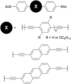
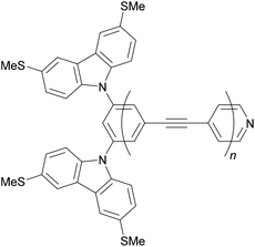
Many studies have experimentally determined values of β for OAEs.60–62,112,124,125,128,172,176,214,240Table 2 shows some of these values together with the structures of the oligomeric series and the junction type used to determine them. Although most of the examples use a similar para-linked OPE repeat unit, the β value varies between 0.5 and 4.2 nm−1 using different anchoring groups and methods. Insightfully, two of the studies examined a sufficient range of oligomer lengths that a distinct reduction in β (ca. 1 order of magnitude) was observed at molecular lengths beyond 2.5–3 nm, as seen in Fig. 26.112,128 This change corresponds to a transition in the charge transport mechanism from tunnelling at short molecular lengths to hopping at longer molecular lengths. A related study of ferrocene-centred OAE-like species (e.g.46, Fig. 25) found a similar transition and reported β = 2.2 nm−1 for the shorter species (albeit based on only two data points).232 Unlike the other studies discussed, which are concerned only with members of homologous series, Kaliginedi et al. combined an OPE oligomer series with OAE3s in which the central aryl unit was varied from benzene to naphthalene to anthracene.125 2,6-Substituted naphthalene and anthracene derivatives (included in Table 2, entry 6) lay on the same trend line as the OPEs and were included when determining β, but 1,4-substituted naphthalene (11) and 9,10-substituted anthracene (p-23) did not and were excluded from the calculation of β (for further discussion see section 3.3).
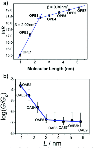 | ||
| Fig. 26 Plots illustrating a transition of β-value with increasing molecular length for: (a) amine-anchored OPEs (entry 1, Table 2); this figure has been adapted from ref. 128 with permission from the American Chemical Society, copyright 2009; (b) pyridine-anchored OAEs (entry 2, Table 2); this figure has been adapted from ref. 112 with permission from the American Chemical Society, copyright 2013. Note that in plot (a) the y-axis represents resistance (i.e. the inverse of conductance) and hence the sign of the slopes differs between the two graphs. | ||
| OAE structure | β/nm−1 and method |
|---|---|
| a For OPE1, benzenedithiol was used rather than the acetyl-protected species. b PEDOT:PSS = poly(3,4-ethylenedioxythiophene) polystyrene sulfonate, a conductive polymer. | |

|
2.0 (OPE1-OPE3), 0.30 (OPE4-OPE7),128 STM-BJ |

|
3.3 (OAE2-OAE5), 0.16 (OAE6-OAE9),112 MCBJ |

|
(a) 2.1 (OPE1-OPE3),240 c-AFM |
| (b) 3.7 (OPE2-OPE4),214 c-AFM | |
| (c) 3.2 (OPE1a-OPE3)/1.1 (OPE2 and OPE3 only),176 STM-BJ | |
| (d) 2.3 (OPE2-OPE4),62 EGaIn | |
| (e) 1.5 (OPE1a-OPE3),124 Large area Au-molecule-PEDOT:PSSb | |

|
2.3 (OPE2-OPE4),62 EGaIn |

|
3.0 (OPE1-OPE3),61 Hg-Drop |
|
3.4 (OPE2-OPE5 + two OAE3s),125 STM-BJ and MCBJ |
|
3.3 (OPE1-OPE3),172 MCBJ |

|
0.5 (OPE1-OPE3),176 STM-BJ |
|
4.2 (OAE1-OAE3),60 c-AFM |
3.2 Connectivity and quantum interference
The discussion at the end of the previous section indicated that the connectivity of an aromatic unit within an OAE can have significant impact on its conductance. This can be attributed to the effects of QI. QI is the source of many differences between molecular and macroscale electronics. The nanoscale conductance pathways through a molecular wire are subject to quantum effects, and electrons propagating through different pathways can interfere with one another constructively (CQI) or destructively (DQI), depending on their phase.31Studies described in section 2.2.1 showed that for benzene rings, para- (and ortho-) connectivity results in higher conductance than meta-connectivity.132,151,152,155–157 This archetypal demonstration of QI is rationalised in Fig. 27 for para- and meta-linked OAE3s with thienyl anchoring groups (p-53 and m-53, Fig. 27a).156Fig. 27b shows the calculated transmission functions of the two wires, which can be separated into HOMO and LUMO contributions as seen in Fig. 27c and d for p-53 and m-53, respectively (higher- and lower-energy orbitals also contribute to a lesser extent, but are discounted for simplicity). Importantly, the HOMO and LUMO contributions have both an amplitude and a phase. In the case of p-53, the phase of transmission is the same for both orbitals within the HOMO–LUMO gap, so CQI takes place and T(E) (and therefore conductance) is high around EF. Conversely, for m-53, a phase difference of π between the transmission through the HOMO and the LUMO in the HOMO–LUMO gap results in DQI,156 meaning T(E) (and therefore conductance) is low around EF. The relationship between para- and meta-type connectivity with CQI and DQI, respectively, has also been demonstrated in OAEs containing larger aryl units such as fluorene.137,138
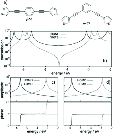 | ||
| Fig. 27 Structures (a) and transmission functions (b) of para- and meta-connected OAE3s p-53 and m-53, together with the amplitude (top) and phase (bottom) of transmission through the HOMO and LUMO of p-53 (c) and m-53 (d). This figure has been adapted from ref. 156 with permission from Wiley-VCH, copyright 2013. | ||
For larger aromatic systems the number of possible pathways increases and QI behaviour necessarily becomes more complex. For polycyclic aromatic hydrocarbons, QI behaviour can be qualitatively predicted using e.g. graphical methods34 or magic ratio rules.117,126 More quantitative predictions rely on the calculation of transmission functions31,32 (see Fig. 6 and section 1.2). The relationship between connectivity, QI and transmission functions was demonstrated experimentally in a comparison of para- and meta-linked OPE3s under external gating.157 Gating shifts the energy of the system away from EF, and therefore should allow access to more conductive regions of the transmission function for molecules that display DQI. In contrast, where CQI occurs T(E) shows little variation until energies close to the molecular orbitals are reached. Indeed, as the gating voltage was varied the conductance of the meta-OPE3 spanned more than 2 orders of magnitude, whereas the conductance of the para-OPE3 varied by only a factor of 3.157
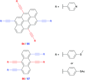
Polycyclic aromatics have been used to demonstrate different extents of CQI derived from connectivity. For a pair of anthanthrene-centred OAE3s (54 and 55, Fig. 28), 6,12-connectivity (54, red) was predicted by magic ratio rules to be 81 times more conductive than 4,10-connectivity (55, blue). MCBJ measurements showed excellent agreement, with a conductance ratio of ca. 79 at maximum junction extension.117 Similar behaviour was observed in SAMs using isomeric anthracene-centred OAE3s (56 and 57, Fig. 28).126 9,10-Connectivity (56, red) was predicted to be 16 times more conductive than 1,5-connectivity (57, blue). The experimental ratios determined using c-AFM were 10.2 (SMe anchoring group) and 14.3 (SAc anchoring group), in reasonable agreement with the prediction.126 The correlation between magic ratio rules and experiment in these cases is impressive, but it should be noted that to our knowledge they have only been shown to apply to all-hydrocarbon aryl units or heteroaryl units derived from bipartite lattices.
QI effects have also been observed in systems with multiple anchoring groups which might be expected to afford independent conductance pathways that interact additively. By comparing OAE2s with a para-pyridyl-, meta-amino- or 2-aminopyridyl-anchor (and a second para- or meta-pyridyl anchor) it was found that parallel conductance pathways do not interact additively (i.e. according to Kirchoff's law) if, in isolation, CQI is expected for one pathway and DQI for the other.185 Instead, the overall conductance of the parallel system was between that of the two isolated pathways. In contrast, where both pathways would be expected to exhibit DQI in isolation, Kirchoff's law appeared to hold.185
3.3 Conjugation
In section 3.1, it was stated that the molecular conductance of OAE3s with central 1,4-substituted naphthalene and 9,10-substituted anthracene units (13 and p-23) did not lie on the same trend line as OPEs when investigating the β-value.125 An increase in conductance as the central ring system increased in size, while the length of the conductance pathway remained the same, was also observed by Liu et al. in an MCBJ-study of five acene-centred OAE3s with central aryl units ranging from benzene to pentacene (25a, 11, p-23, 58 and 59, Fig. 29a).69 This behaviour relates to the conjugation of the central aryl unit. As the size of the acene, and hence conjugation, increases the HOMO–LUMO gap decreases. This, in turn, results in increased conductance as seen in the molecular transmission functions (Fig. 29b); the smaller HOMO–LUMO gap reduces the depth of the transmission minimum close to EF.69 It is noteworthy that Liu et al. did not observe the same trend when SAMs of the molecules were measured using the EGaIn method. In this case conductance was fairly similar for all OAEs except for the pentacene system, for which it was significantly lower.69 This was attributed to intermolecular packing interactions between acene units in the tightly-packed SAM (which is also believed to be the source of lower-conductance features present in the MCBJ data).69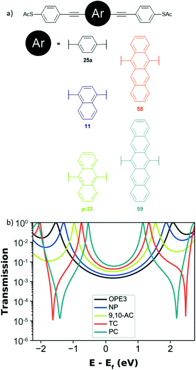 | ||
| Fig. 29 (a) Structures of a series of thiol-anchored acene-centred OAE3s. The core acenes are: para-benzene (OPE3, 25a), 1,4-naphthalene (NP, 11), 9,10-anthracene (9,10-AC, p-23), 5,12-tetracene (TC, 58) and 6,13-pentacene (PC, 59); (b) Nonequilibrium Green's Function-Density Functional Theory (NEGF-DFT) based transmission functions for the molecules in (a). Panel (b) has been reproduced from ref. 69 with permission from the American Chemical Society, copyright 2020. | ||
The impact of cross-conjugation on QI has been investigated by comparing aromatic systems to their quinoidal analogues. Linearly-conjugated 2,6-anthracene-centred OAE3 systems (e.g.12) have been compared to cross-conjugated anthraquinone analogues (e.g.32) in conductance studies using MCBJ,125 STM-BJ,67 c-AFM67,214 and EGaIn.65,67 Non-conjugated 9,10-dihydroanthracene species (e.g.60) are often also included. As shown in Fig. 30, anthracene systems are consistently the most conductive, followed by 9,10-dihydroanthracenes, then anthraquinones. For 2,6-connectivity, conductance therefore follows the trend of linear conjugation > no π-conjugation > cross-conjugation. Charge transport calculations illustrate that this can be related to DQI in the case of anthraquinone species.125,214
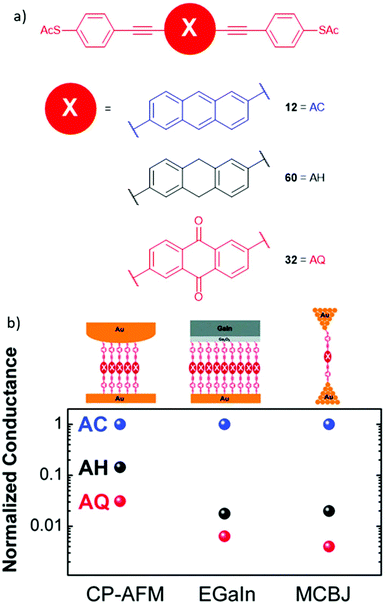 | ||
| Fig. 30 Structures (a) and comparison of conductances (b) of thiol-anchored OAE3 and OAE3-like species with central 2,6-connected anthracene (AC, blue, 14), 9,10-dihydroanthracene (AH, black, 60) and anthraquinone (AQ, red, 41) units determined using different experimental methods (CP-AFM = c-AFM). This figure has been adapted from ref. 214 with permission from the PCCP Owner Societies, copyright 2013. Some of the data included is originally from other works.65,125 | ||
DQI is not a fundamental property of the anthraquinone unit; a comparison of 1,4- and 1,5-connectivities (where the conductance pathway respectively does or does not pass across the quinoidal ring, i.e. the wire is either linearly or cross-conjugated) shows no evidence of DQI in the 1,4-case.215 The conductance of the 1,5-species is much lower than the 1,4-analogue, which is attributed to DQI in the former (although the characteristic antiresonance is not seen in the calculated transmission function).215 Electrochemical reduction to the conjugated dihydroxyanthracene derivative increased conductance in both cases, but much more significantly for the 1,5-connectivity. This was related to the “switching off” of DQI in this case.215 Similar redox-switching behaviour has been reported for 2,6-connected anthraquinone217 and an anthraquinone-derived extended TCNQ unit.63 A theoretical study indicated that the connectivity of cross-conjugated anthraquinones can influence QI behaviour;241 this observation has recently been rationalised using an approach based on curly arrows.34
Zhang et al. used OAE3s containing benzodithiophene (BDT) derivatives to investigate the relationship between conjugation and QI.66 A linearly-conjugated BDT (17) was compared to its quinone analogue (35) and an isomeric cross-conjugated BDT (61), alongside an anthraquinone species (32) for reference. Compared to linearly-conjugated 17, cross-conjugation alone was observed to reduce conductance much less than cross-conjugation due to a quinoidal system (Fig. 31). Calculated transmission functions showed that for the quinoidal systems a sharp DQI feature was present close to EF, whereas for the cross-conjugated isomer the equivalent antiresonance was significantly shifted towards the HOMO.66 A key finding of this study is therefore that the nature of the functionality which imparts cross-conjugation has substantial influence on the resulting QI behaviour. A study that examined a series of OAE3s with central anthraquinone-like species with different cross-conjugating groups also found considerable variation in conductance.67
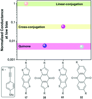 | ||
| Fig. 31 Comparison of the conductance of three OAE3s incorporating BDT derivatives and an anthraquinone species measured using the EGaIn method. This figure has been adapted from ref. 66 with permission from The Royal Society of Chemistry, copyright 2018. | ||
Cross-conjugation has also been shown to supress the reduction in conductance associated with DQI. In a comparison of OAE3s with central dimethylfluorene or fluorenone units (62 and 63 in Fig. 32) para-connectivity (62, red) afforded higher conductance than meta-connectivity (63, blue).138 However, the magnitude of this difference was significantly lower for the fluorenone species 62b and 63b (2–3 times lower) than the dimethylfluorene species 62a and 63a (ca. 2 orders of magnitude lower). The carbonyl group of meta-linked fluorenone 63b is cross-conjugated with the anchoring groups, whereas there is no cross-conjugated functionality in the dimethylfluorene analogue 63a, suggesting that this small structural change is responsible for the drastically different conductance behaviour.138
3.4 Aromaticity and heteroatom effects
Heterocyclic systems have been used as arylene units in OAEs to investigate the effects of aromaticity on molecular conductance. For simple five-membered heterocycles, aromaticity increases in the order furan < pyrrole < thiophene; cyclopentadiene is a non-aromatic analogue that can easily be compared with this series. Chen et al. studied amine-anchored OAE3s with central thiophene, furan or dimethylcyclopentadiene rings (64b–d in Fig. 33) and found that conductance decreased as the aromaticity of the central ring increased.133 A later study by Yang et al. using pyridyl anchoring groups saw no variation with aromaticity for an analogous series of OAE3s also including a pyrrole derivative (8a–d in Fig. 33).118 The difference between the two studies was attributed to anchoring group effects.118 Contrasting results were observed with an asymmetric connectivity (65a–d in Fig. 33). In this case the pyrrole- and furan-centred species were the most conductive, followed by the cyclopentadiene derivative, then the thiophene-centred OAE3.118 Conductance appeared to increase with the electronegativity of the varied group rather than relating to aromaticity.118 The transmission functions of the asymmetric series also showed evidence of DQI (cf. meta-connectivity).A related study of “bridged biphenyl” species (15a–d, and 66a–d in Fig. 33) also explored the effects of aromaticity and heteroatoms on the conductance of OAE3s.137 For para-connectivity (15, red), conductance decreased as the aromaticity of the heterocyclic core increased. The overall trend in conductance was X = O > NEt > CMe2 > S, meaning that the non-aromatic dimethylfluorene species (15d) did not follow the aromaticity trend.137 Contrasting results were obtained for meta-connectivity (66, blue) where conductance followed the trend X = CMe2 ≈ NEt > O ≈ S. Aromaticity alone cannot explain this conductance trend, and as for five-membered heterocycles118 electronegativity and QI appear to be important factors.137 In an alternative rationalisation, the heteroatoms can also be considered as cross-conjugating functionality34 (cf. the discussion of the structurally-similar fluorenone-containing OAE 63b above138). Additional evidence supporting an inversely proportional relationship between aromaticity and conductance is desirable, but these studies suggest it may prove difficult to conclusively separate the effects of aromaticity from associated factors.
Heteroatom effects have also been considered separately from aromaticity. The influence of heteroatoms, either within the OAE backbone or as pendent substituents, is minimal in the case of linearly-conjugated species for which CQI is expected to occur.93,112,131,201 In contrast, clear effects are seen when heteroatoms are introduced into meta-linked OAEs for which DQI is expected. Liu et al. compared a meta-OPE3 to analogous OAEs in which the central ring is pyridine rather than benzene.132 Using the MCBJ method, they observed different conductance behaviour depending on the position of the nitrogen in the central ring (Fig. 34). When the nitrogen was meta to both alkynes (M1, Fig. 34), the conductance was comparable to the parent OPE3. The other two isomers (M2 and M3) each have higher conductance than the parent system.132
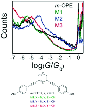 | ||
| Fig. 34 MCBJ conductance histograms (top) and structures (bottom) for a series of meta-OAE3 molecular wires. This figure has been adapted from ref. 132 with permission from Wiley-VCH, copyright 2016. | ||
Comparable effects were seen in an investigation of meta-linked OPE3s with methoxy-substituted analogues,153 indicating that pendent heteroatoms can also influence conductance. In this case, substitution in the mutually meta-position (relative to the alkynes) again afforded similar conductance to the parent system, whereas enhanced conductance was observed for substitution para to one alkyne and ortho to the other.153 In STM-BJ studies, substitution at the mutually ortho position did not afford an increase in conductance. However, computational studies showed this was a steric rather than an electronic effect; enhanced conductance was seen in the transmission function if the methoxy substituent was constrained to an unfavourable position in which its lone pair could interact with the OPE π-system.153
These132,153 and other studies34–36 have related the increased conductance associated with the addition of heteroatoms to meta-linked OAEs to the electron-withdrawing or -donating properties of the heteroatom(s). Charge transport simulations showed that the presence of donor or acceptor groups at certain positions shifted DQI antiresonances away from EF, meaning T(E) and hence conductance was higher in this region.35,36 Further experimental confirmation of these effects (including the scope of suitable functional groups), and analysis of their influence on measured molecular conductance would provide a means to better design new molecules which exploit these DQI effects.
OAE3s with central five-membered heterocycles containing different chalcogens (67, Fig. 35a) were used in a study of gating effects on molecular conductance.134 Without gating, molecular conductance followed the trend X = O < S < Se. This was the inverse of the trend in HOMO–LUMO gaps for which X = Se < S < O.134 When gating voltages ranging from −0.9 to +0.3 V were applied, the range of possible conductance values followed the order X = O < S < Se, with those of the X = Se species spanning an order of magnitude. The gated conductances showed reasonable agreement with the calculated transmission functions for the molecules, as shown in Fig. 35b.134 The observed variation of the gating effect with relatively small structural changes is pertinent to the design of molecular transistors.
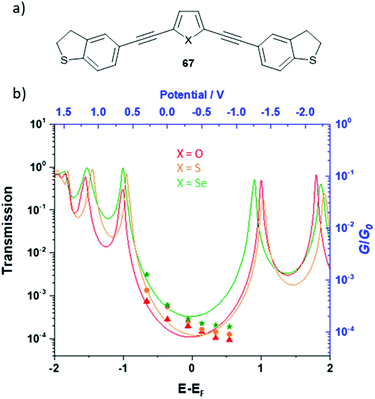 | ||
| Fig. 35 (a) General structure of DHBT-anchored OAE3 wires 67 with a central heterocycle used to study gating effects on molecular conductance; (b) transmission functions (solid lines, black axes) and electrochemically gated STM-BJ conductance data (data points, blue axes) for OAE wires in (a) with X = O, S and Se. Panel (b) has been adapted from ref. 134, with permission from the American Chemical Society, copyright 2021. | ||
3.5 Antiaromaticity
Aromatic systems have also been compared to related antiaromatic species. Gantenbein et al. compared different connectivities of biphenylene in OAE3s with structurally similar aromatic systems (Fig. 36).136 Wire 44, where the conductance pathway crosses the antiaromatic 4 π e− central ring, was compared to OAE3s with central fluorene (62, R = para–(methylthio)phenyl) or biphenyl (68) units, i.e. with a non-aromatic or without any central ring. No significant conductance variation was seen between these three species.136 OAE3s with 1,4-connectivity across central biphenylene (69), naphthalene (70) and anthracene (71) units were also compared. In these cases the fused (anti)aromatic ring(s) are pendent to the conductance pathway. Again, no significant conductance variation was observed.136 The limited effect of antiaromaticity in these cases could relate to the fusion of the antiaromatic cyclobutadiene system to aromatic benzene rings in biphenylene. This may reduce the effective antiaromaticity of the system as a whole.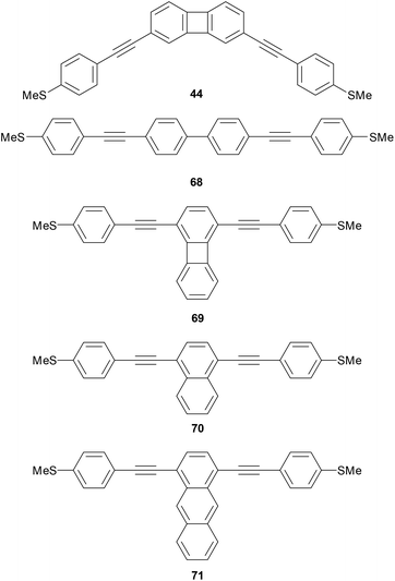 | ||
| Fig. 36 Structures of biphenylene-containing molecular wires and selected reference species used to investigate the effect of antiaromaticity on molecular conductance. | ||
To further investigate antiaromaticity, Schmidt et al. compared dibenzopentalene-centred OAE3s 72 and 73 with two aromatic model systems: a 9,10-anthracene-centred OAE3 (74) and an OPE3 (75) (Fig. 37).230 The 8 π e− pentalene system at the core of dibenzopentalene is antiaromatic. The conductance pathways of 72 and model systems 74 and 75 are near-identical in length and comprise equivalent alternating single and multiple bonds. The conductance of these three systems is similar (Fig. 37), although that of 75 is slightly lower due to its larger HOMO–LUMO gap (cf. the acene series6925a, 11, p-23, 58 and 59 in Fig. 29).23073 has a longer conductance pathway but is significantly less conductive relative to 72 than would be expected based on this length difference alone. The conductance difference appears to relate to cross-conjugation rather than the antiaromaticity of dibenzopentalene, as supported by the presence of an antiresonance in the transmission function of 73.230 Small antiaromatic systems fused to aromatic rings appear to have only minimal influence on molecular conductance.
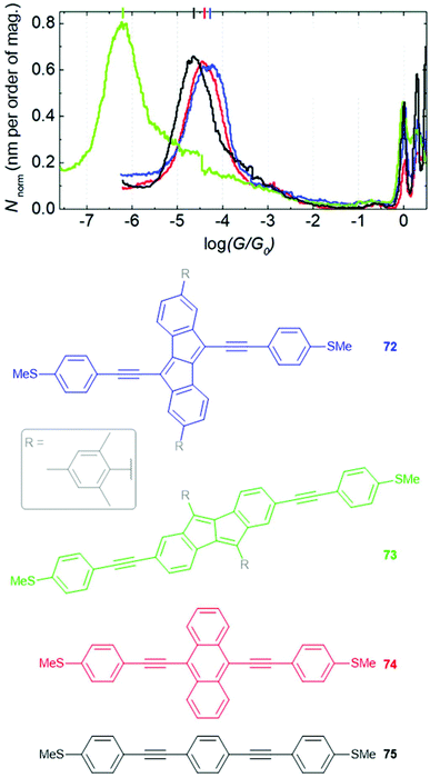 | ||
| Fig. 37 STM-BJ 1D Conductance histograms (above) and structures (below) of OAE3 wires used by Schmidt et al. to investigate the effects of antiaromaticity on molecular conductance. The structures are coloured to match the corresponding histogram trace. This figure has been adapted from ref. 230 with permission from the Royal Society of Chemistry, copyright 2021. | ||
3.6 Anchoring groups
Comparisons between anchoring groups are not always straightforward as they may rely on results obtained in different laboratories using different experimental equipment and methods.158 However, multiple studies have specifically examined the effect of changing the anchoring group of otherwise identical OAEs. Reported trends include:1. Conductance of OAE2s varies with anchoring group in the sequence –SAc > –NH2 > pyridyl ≫ –CN, using STM-BJ and MCBJ. Thiol and pyridyl groups gave the most stable junctions, and showed the highest junction formation probability.160
2. Based on values for OAE2s in a study of oligoynes, the trend for conductance with anchoring group is DHBT > –SAc > –NH2 > pyridyl ≫ –CN, using STM-BJ and MCBJ. DHBT, thiol and pyridyl groups all showed high junction formation probability.102
3. A series of alkyne-anchored OPEs were more conductive than their thiol analogues in an MCBJ study.172
4. A study of OAE3s found conductance followed the trend –SAc > –SMe ≈ –NH2 > pyridyl, whereas a study of junction lifetimes gave the trend pyridyl > –SAc ≈ –NH2 > –SMe.161
5. Solvent effects on the conductance of OAE2 wires varied with anchoring group in MCBJ measurements. With –SMe anchors, conductance increased by almost an order of magnitude when the solvent was changed from mesitylene to THF, whereas smaller changes were seen for –SAc or pyridyl anchors.242
6. The effect of copper complexation on the conductance of phenanthroline-centred OAE3s 21a–c (Fig. 13) differed depending on the anchoring group in “self-breaking” MCBJ experiments.148 For the free wires, conductance followed the trend SAc > alkyne > pyridyl. Upon Cu-complexation, the conductance of the thiol-anchored OAE3 fell slightly, while that of the alkyne-anchored OAE3 fell by an order of magnitude. In contrast, the conductance of the pyridine-anchored OAE3 increased by a factor of ca. 6. The different responses were attributed to the dominance of different molecular orbitals on conductance behaviour, as complexation changes orbital energies.148
Anchor groups influence which molecular orbital dominates the conductance properties of a molecular wire (i.e. whether the HOMO or LUMO is closer in energy to EF in the transmission function, see Fig. 6). This phenomenon is of particular relevance to the thermoelectric properties of molecular wires and is discussed further in section 4.1.
4 Thermoelectric properties of OAEs
This section is concerned with the measurement of thermal properties of OAEs in molecular junctions. Molecular wires such as OPEs have been proposed as candidate materials for low-cost, environmentally-friendly thermoelectric generators,27–29i.e. devices that can harvest (waste) heat and transform it into electricity. An effective thermoelectric material should conduct electrons efficiently and heat poorly. Thermoelectric performance can be summarised using a ‘thermoelectric figure of merit,’ ZT,27–29 according to the equation:A higher ZT indicates more favourable performance. The electrical conductance, G, was discussed in detail in section 3. S is the Seebeck coefficient, or thermopower, of a material. T is the temperature of the material (although as a thermoelectric device is reliant on a temperature gradient this term can prove problematic to define in practice).243 The terms κp and κe represent the thermal conductance due to phonons and electrons, respectively, and may be combined into a single κ term representing total thermal conductance.
Experimentally, the Seebeck coefficient of a molecular wire is determined by measuring the thermoelectric voltage (ΔV) across a molecular junction with different temperature differentials (ΔT) between the electrodes. A plot of ΔV against ΔT should be linear with a gradient of −S.33,85 Transmission function calculations used in molecular conductance studies (Fig. 6) also provide information about the Seebeck coefficient. S is proportional to the slope of T(E), but has the opposite sign. When the HOMO is closest to EF, T(E) has negative slope at EF and S is therefore positive. The opposite holds when the LUMO is closest to EF.85 DQI antiresonances can result in large gradients of T(E) in the HOMO–LUMO gap and have been identified as a potential means to increase S.244 However, as discussed in section 3.2, DQI results in reduced electronic conductance so the resulting increase in S may not afford a concomitant increase in ZT. It has been proposed that by carefully controlling the position of a DQI feature, S could be increased without significantly reducing G;34,244 note that the direction in which an antiresonance is shifted would affect the slope of T(E) and hence the sign of S.
Surprisingly, given their ubiquity in charge transport studies, relatively few experimental studies have investigated the thermoelectric properties of OAEs, particularly with respect to structure–property relationships. Oligophenylenes are much more prevalent.29,30 Substituted benzene rings are therefore widely studied, including in the earliest report of Seebeck coefficients for single molecules from 2007.85
4.1 Influence of anchoring groups on Seebeck coefficient
A key insight of early molecular thermopower studies is that the sign of the Seebeck coefficient is dependent on the anchoring group of the molecule. This is logical as the anchoring group determines the dominant orbital for conductance, and hence the slope of T(E) at EF.33 Early studies of functionalised benzenes showed that S was positive for thiol33,85,203,245 and amine245 anchoring groups but negative for nitrile anchoring groups.203 Subsequent studies of OAEs agree with these observations for thiols and amines,86,152 and additionally show that S is negative for pyridyl,139,246 methylthio126,139,246 and DHBT202 anchoring groups. Interestingly, the structurally similar DMBT anchoring group was found to afford positive values of S.166 The electrode material has been shown to affect S; changing from Au to Ni electrodes in an STM-BJ study saw S change from positive to negative for benzene-1,4-dithiol. This was attributed to spin hybridisation between the molecular orbitals and the Ni electrodes.247Anchoring group effects in larger OAEs were investigated using c-AFM in a comparison of OAE3s with central 9,10-connected anthracene units (76, 77, 74 and p-23, Fig. 38). These varied only in their anchoring groups, which were either both pyridyl (76), both methylthio (74), one of each (77), or both (acetyl protected) thiols (p-23).139 As shown in Fig. 38, the magnitude of S was low for the bispyridyl species 76 (−2.50 μV K−1), increased by a factor of ca. 2 when one pyridyl was replaced by para-(methylthio)phenyl to give 77, and increased significantly to −21.6 μV K−1 for 74, with two para-(methylthio)phenyl anchors. For thiol anchored p-23 the sign of S was positive, with an intermediate magnitude (+11.0 μV K−1) compared to analogues 76 and 74.139 The tenfold increase in S for –SMe vs. pyridyl anchors highlights the importance of anchor group selection in the design of OAEs for thermoelectric applications. The authors highlighted the relevance of strategies for structural control of S in thin films to future device applications.
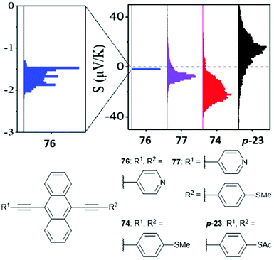 | ||
| Fig. 38 Seebeck coefficient distributions from c-AFM studies (above) and structures (below) of OAE3 wires used by Ismael et al. to investigate anchoring group effects on thermopower in OAEs. This figure has been reproduced from ref. 139 with permission from The Royal Society of Chemistry, copyright 2020. | ||
It should be noted that the structure–property relationships described above are not necessarily transferable to other systems. For example, for biphenylene-centred OAE3s the magnitude of S was found to be larger with pyridyl anchoring groups (−9.71 ± 1.06 μV K−1) than with –SMe anchoring groups (−6.88 ± 0.67 μV K−1).246 However, in this case a DQI feature was observed in the transmission function of the pyridyl-anchored system, but not the –SMe anchored system. Clear scope remains for in-depth studies to better define all aspects of the relationship between anchoring groups, other structural features, electrode material, and the sign and magnitude of S.
4.2 Seebeck coefficient: structure–property relationships
Investigations into the effect of structural features of OAEs other than the anchoring group on S are relatively rare. These predominantly recent works consider similar properties to comparable studies of electronic conductance: connectivity and QI, conjugation and aromaticity, and side groups.Miao et al. determined S for para- and meta-connected OPE3 dithiols in one of the first experimental studies to compare the effects of CQI and DQI on thermopower.152S was higher for meta-connectivity when measured using both STM-BJ (meta: +20.9 ± 15.4 μV K−1, para: +10.8 ± 9.5 μV K−1) and AFM (meta: +22.5 ± 1.1 μV K−1, para: +8.0 ± 0.8 μV K−1, Fig. 39a and b).152 These results agreed with expectations based on transmission function calculations, in which the DQI feature associated with meta-connectivity increased the slope of T(E) around EF, and hence the magnitude of S, relative to para-connectivity (Fig. 39c). This crucial experimental confirmation of theoretical predictions that QI could be used to manipulate thermoelectric properties prompted many subsequent studies of structure–property relationships.
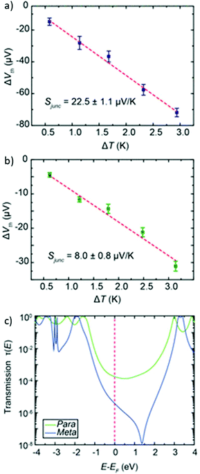 | ||
| Fig. 39 Thermoelectric voltage as a function of ΔT for monolayers of meta-OPE3 dithiol (a) and para-OPE3 dithiol (b) determined using an AFM method (N.B. the gradient of these plots is equal to −S), and calculated transmission functions for single-molecule junctions containing the same molecules (c). This figure has been adapted from ref. 152 with permission from the American Chemical Society, copyright 2018. | ||
Wang et al. compared two different conductance pathways for which CQI occurs using differently connected anthracene-centred OAE3s with thiol and methylthio anchors (56 and 57 in Fig. 28).126 As discussed in section 3.2, regardless of the anchoring group, electronic conductance was higher for 9,10- (56, red) than 1,5-connectivity (57, blue). In contrast, the effect of connectivity on S depended on the anchoring group. For –SMe anchoring (negative S), the magnitude of S was larger for the less conductive isomer 57 (−31.8 μV K−1 for 1,5- vs. −23.4 μV K−1 for 9,10-connectivity) whereas for thiol anchoring (positive S) the more conductive isomer 56 also had higher S (+10.4 μV K−1 for 1,5- vs. +12.1 μV K−1 for 9,10-connectivity).126 Analysis of the transmission functions emphasised the sensitivity of S to molecular orbital energies and the need to correctly determine EF in theoretical studies. While it is clear that CQI can be used to enhance S, the concomitant effects of anchoring groups are likely to make design of such systems more challenging than those based on DQI.
A comparison of methylthio-anchored OAE3s with central 1,4-connected biphenylene, naphthalene and anthracene units (69–71, respectively, Fig. 36) explored the effects of antiaromaticity and conjugation on S.246 Calculations showed that the energy of the LUMO was similar for all three systems, but that the HOMO–LUMO gap decreased in size as the central unit was varied from biphenylene to naphthalene to anthracene. The slope of T(E) at (an empirically corrected) EF suggested that the magnitude of S should follow the trend 69 > 70 > 71, as the centre of the HOMO–LUMO gap lies closer to (the corrected) EF as conjugation increases. Experimentally the magnitude of S followed the trend 69 (−6.88 ± 1.06 μV K−1) > 71 (−4.13 ± 1.52 μV K−1) > 70 (−1.62 ± 0.21 μV K−1), which can be corrected for computationally by adjusting the energy levels.246 There was no clear relationship between S and conjugation, the energetics of the system appeared to be more influential.
Side group functionalisation was shown to have a small effect on the thermopower of benzene-1,4-dithiol derivatives in 2008.203 Similarly limited variation of S was observed recently by Dekkiche et al. in a comparison of DHBT-anchored OAE3s in which the central aryl unit was varied between benzene, 2,5-dimethoxybenzene and 9,10-connected anthracene.202 In this series, S was largest for the benzene species (−11.4 ± 0.5 μV K−1), followed by the anthracene (−8.7 ± 1.6 μV K−1) then the dimethoxybenzene derivative (−7.9 ± 1.3 μV K−1). This trend could not be easily rationalised using transmission functions; the conductance is LUMO dominated but calculations could not accurately reproduce the subtle differences within the series.202 As for the above study where conjugation was varied,246 precise energetics appear to be more influential than structural effects. An interesting and unexpected observation was that the anthracene-centred wire displayed enhanced thermal stability compared to the rest of the series, allowing data to be collected for a larger range of ΔT values.202
The thermopower of DMBT-anchored OPEs was recently compared to related metal bis(acetylide) complexes. S increased by up to ca. 50% upon replacement of the central benzene ring of an OPE3 with a Ru or Pd centre, although in all cases the measured values were modest, with a maximum of +7.1 μV K−1 for the Ru complex.166
Based on these early studies, it remains to be seen whether clear structure–property relationships relating to S will be established to the same extent as those relating to G discussed in section 3. It remains a challenge to separate the effects of different structural factors from both one another and influences such as the energetics of the junction. This is further complicated by the often small variation in S for structurally similar systems.
4.3 Thermal conductance
Theoretical studies of OPEs have shown that structural modifications influence κp, which is the dominant contributor to thermal conductance at room temperature.248meta-Connectivity afforded lower κp than para-connectivity due to phonon interference effects; this effect was more pronounced for OPE3 systems than for OPE1 species (i.e. single benzene rings).248,249 Calculations have also shown that replacing a proton with a halogen substituent reduced κp for OPE3 and OPE1 species, with a larger reduction in κp as the mass of the halogen increases.248Experimental determination of κ for molecular junctions is challenging.250 Approaches based on laser spectroscopy and scanning thermal microscopy exist, but have primarily been applied to alkanethiols.250 However, one of the first studies of single-molecule thermal conductance compared OPE3 dithiol with 1,8-octanedithiol.89 This ground-breaking work utilised a specially designed suspended micro-electro-mechanical system (MEMS) as a substrate for molecular assembly in conjunction with a custom-built STM-BJ setup (Fig. 40a). The thermal conductance of OPE3 dithiol (20 ± 6 pW K−1, Fig. 40b) was lower than that of octanedithiol (29 ± 8 pW K−1, Fig. 40c).89 The authors note that this variation is fairly small, and highlight the potential of phonon engineering strategies, such as phonon interference,251 as a means to minimise κ and to increase ZT. Structure–property relationships within series of OAEs have promise as a means to increase understanding of phonon engineering, provided that the capability to carry out single-molecule thermal conductance studies becomes more widespread.
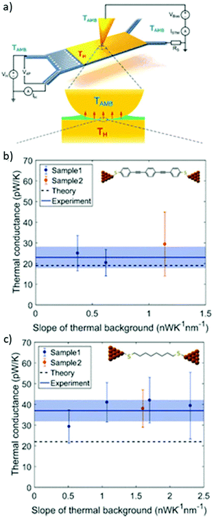 | ||
| Fig. 40 (a) Illustration of the MEMS/STM-BJ setup used by Mosso et al. to determine single molecule thermal conductance; (b) data used to determine the single molecule thermal conductance of OPE3 dithiol; (c) data used to determine the single molecule thermal conductance of octanedithiol. This figure has been reproduced from ref. 89 with permission from the American Chemical Society, copyright 2019. | ||
A key consequence of the recent development of methods to experimentally determine κ is that it is now possible to measure each of the values that contribute to the thermoelectric figure of merit ZT (i.e. G, S, T and κ). This is of fundamental importance to the characterisation of materials for thermoelectric applications, for which optimisation of ZT is required in order to achieve viable devices.
4.4 Outlook
Most studies of the thermoelectric properties of OAEs are from the last few years. Moving forward OAEs have the potential to become the workhorse molecules of molecular thermoelectric research, paralleling their role in molecular electronics. It is reasonable to anticipate studies seeking a clearer understanding of structural effects on S and κ in order to optimise ZT. The wide structural variation possible with OAEs provides clear opportunities in phonon engineering, particularly as experimental measurements of thermal conductance become more accessible.5 Recent developments and future prospects
The previous section anticipated growing interest in the thermoelectric properties of OAEs in the near future. This section will consider some other recent developments that are likely to influence future studies of OAEs in junctions.5.1 Data analysis
In recent years considerable efforts have been made to apply machine learning to the analysis of molecular conductance traces. In early single-molecule conductance studies manual selection of conductance traces was not uncommon,24 despite being time-consuming and carrying a risk of bias.167 The development of data sorting methods such as clustering algorithms provides an opportunity to analyse data objectively and gain even more detailed insight into the behaviour of molecules in junctions. Many of these methods were pioneered using datasets collected for OAE derivatives.69,146,167,178,252–256The utility of these techniques is exemplified by a study of porphyrin-centred OAE3s by El Abbassi et al., who used a clustering algorithm in conjunction with a range of model systems to assign classes of conductance trace to different junction geometries (Fig. 41).146 Note the identification of unconventional anchoring behaviour assigned to the less conductive classes B and C. The model systems each contained different features of the molecule shown in Fig. 41. By applying the clustering algorithm to conductance data for each model system, classes could be associated with specific structural features and the junction geometry deduced. This emphasises the importance of interdisciplinary collaboration in molecular electronics: additional synthesis greatly enhanced the outcome of the data analysis. The proposal of novel conductance pathways also lends itself to associated computational work, as these junction geometries can be modelled. Automated data analysis methods of this type will likely become commonplace in single-molecule conductance studies. They permit analysis of highly functionalised molecular wires that are likely to afford complex conductance traces.
 | ||
| Fig. 41 Junction geometries associated with three classes of conductance trace assigned using a clustering algorithm and model systems. This figure has been reproduced from ref. 146 with permission from The Royal Society of Chemistry, copyright 2019. | ||
5.2 Junction materials and methods
Historically, molecular junctions have relied on metallic electrodes, with single-molecule studies particularly reliant on gold electrodes. The above discussion has already made clear the growing interest in alternative junction materials and designs, including nickel electrodes in STM-BJ studies,247 ITO–molecule–Au junctions165 and bridging nanogaps between CNT76,77 or graphene73–75 electrodes with molecules. Graphene-based junctions are of particular interest owing to the notable properties of graphene and its compatibility with organic materials.257 Recently, two graphene-based MCBJ approaches have been reported. The first is based directly on the breaking of a graphene sheet suspended between gold electrodes,258 but to our knowledge has not yet been applied to the study of molecular junctions. A second approach with graphene-coated copper wires as electrodes has been used to measure the conductance of various fullerenes259 and the cross-plane transport of a series of polycyclic aromatic hydrocarbons.260The development of new approaches and innovations for junctions with metal electrodes also continues. One recent example is based on the closure of nanogaps pre-coated with molecules using electrical field migration. A nanogap pre-treated with 1,4-benzenedithiol was subjected to I–V sweeps and repeatedly exhibited a conductance corresponding to that observed for the same molecule in an MCBJ.261 Another innovative development is the use of an external electric field to influence junction formation probability in STM-BJ experiments.262 It was found that OPEs with methylthio anchoring groups were increasingly likely to form junctions as the bias was increased, whereas thiol, amine and pyridyl anchors all showed reduced junction formation probability with increasing bias. This meant it was possible to demonstrate selective, preferential junction formation in a mixture of methylthio- and thiol-anchored OPEs based on the applied electric field.262
OAE derivatives are outstanding candidate molecules for developing novel molecular junction methodologies and as benchmark compounds for investigations of modifications to existing techniques. The ease with which structural modification can be achieved facilitates the translation of OAE wires to new electrode surfaces that require alternative anchoring groups.
5.3 Molecular spintronics
In spintronics, electrons serve as more than simple charge carriers; their spin is also important, and can be used to create logic or memory devices.263 The idea of designing molecular wires with spintronic applications is longstanding,264,265 but experimental studies are an area of relatively recent and increasing growth. Radical functionalised OPE-like materials were identified as candidate spin-filters in a computational study in 2010.265 The proposed materials did not, however, have structures associated with stable radicals. A study of an OPE3 with a side group bearing a stable (2,2,6,6-tetramethylpiperidin-1-yl)oxyl (TEMPO) radical (78, Fig. 42) determined that this system, in which the radical is not conjugated to the backbone, was not a promising spin filter.266 However, experimental studies showed that 78 displayed unprecedentedly large magnetoresistance, much higher than that of an unfunctionalised OPE3.266The limited spin filtering behaviour of 78 is supported by a recent computational study of other structurally similar radical-bearing OPE3s, which found that good orbital overlap between the π-systems of the OPE backbone and radical is needed to achieve appreciable spin filtering.267 Unfortunately this is difficult to achieve experimentally as significant steric shielding, which promotes divergence from coplanarity, is usually required to stabilise organic radicals. It was noted that larger spin polarisation (and potentially enhanced Kondo features, see below) might be achieved by using meta-OPE analogues, where reduced intramolecular steric hindrance would be expected.267 This would lead to a more coplanar backbone and hence increased spin delocalisation along the OPE wire, although as discussed in section 3.2 lower overall conductance would be expected. Incorporating radical functionality directly into the molecular backbone may not be straightforward either; a (non-OAE) molecular wire with an otherwise stable Blatter radical in its backbone appeared to oxidise to a closed-shell species when bound between electrodes in STM-BJ experiments.268
An alternative approach to molecular spintronics is the use of junctions based on ferromagnetic electrodes, which have a different density of states for spin-up and spin-down electrons. Hybridisation upon binding with a molecule creates spin polarised molecular orbitals, and therefore the resulting molecular junctions have potential as spin filters.269 The combination of nickel electrodes and a series of OAE3 wires has been investigated computationally.270 By considering meta-OPE3 and analogous meta-OAE3s substituted with heteroatoms (both within the backbone and as pendent substituents) it was found that the location of a DQI feature affects not only the magnitude of conductance, as discussed in section 3.4, but also the extent of spin polarisation. The least conductive species gave the highest spin polarisation. However, through appropriate heteroatom substitution relatively high spin selectivity was achieved alongside appreciable molecular conductance.270 OAE wires designed for QI studies should therefore have experimental utility in spintronics in the near-future. Ni break junctions have already been developed,247,271 and methods to experimentally analyse spin filtering in molecular junctions have been demonstrated.272 Combining these techniques with appropriate molecules, such as OAEs, should allow detailed interdisciplinary studies of molecular spintronics. As a general rule low-spin and high-spin states are stable at low and high temperatures, respectively, and low temperature vacuum conditions are required to achieve a stable reversible spin switch.273 Therefore, it is an interesting challenge to raise operating temperatures to room temperature.
The Kondo effect, which is associated with unpaired spins, is another spin phenomenon that is of interest in molecular junction studies,19,274 with potential applications in switchable devices. The Kondo effect has been observed in junctions containing molecules bearing an unpaired electron and derives from interactions between electrons including the Pauli exclusion principle (see ref. 274 for a more detailed overview, which is beyond the scope of the present discussion). A typical manifestation in molecular junctions containing a spin-½ feature is the presence of a distinct zero-bias conductance below a critical Kondo temperature, TK. Cryogenic conditions are required to access TK, which for single-molecule junctions is typically on the order of tens of Kelvin or below.211,274,275 There are relatively few examples of OAE wires that display the Kondo effect as many studies have selected alternative backbones to more easily incorporate unpaired spins in the form of e.g. triphenylmethane radicals276 or metal complexes.277,278
The OPE5-exTTF cruciform molecule 79 (Fig. 43a, top) was studied experimentally in a three-terminal device to probe electrical control of organic magnetism.211 The molecule was reversibly switched between three redox states and the resulting radicals were found to couple antiferromagnetically or ferromagnetically depending on the relative locations of the charges on the molecular backbone. Differing Kondo features and zero-bias conductances were observed for the various charged states due to the differing number of interacting spins (Fig. 43b–d).211 The system was described as acting like a two-qubit gate, indicating the potential of Kondo effect molecules in quantum computing applications.
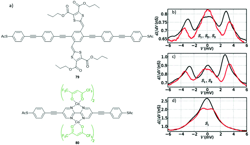 | ||
| Fig. 43 (a) Structures of OAE wires used in studies investigating the Kondo effect; (b–d) Differential conductance versus voltage for a junction containing (deprotected) molecule 79 averaged over different gating voltage ranges [(b): 0.2–0.4 V, (c) 1.4–1.5 V, (d) 2.4–2.5 V] with either zero (black lines) or 8 T (red lines) applied magnetic field. The SX notation (X = 1–3) indicates the spin states interacting in each bias range. In each case, the non-zero conductance at zero-bias is indicative of the Kondo effect. Panels (b–d) have been reproduced from ref. 211 with permission from the American Physical Society, copyright 2012. | ||
Kondo-like behaviour was reported for the dinuclear Co(II) complex 80 (Fig. 43a, bottom) in which the two metal ions (bearing ancillary ligands) are each bound to the same OAE3 wire with a central ligating bipyrimidine unit.275 Switching behaviour based on applied bias was assigned to the existence of pseudo-singlet and pseudo-triplet states. The latter state is magnetically active and exhibited a zero-bias conductance feature that could be split by an applied magnetic field, as seen for Kondo features in other studies.275 In contrast, the pseudo-singlet state and the free ligand did not display Kondo-like properties.
Behaviour resembling the Kondo effect was observed for TEMPO-functionalised wire 78 (Fig. 42). However, the authors of the study do not definitively assign the observed zero-bias conductance to the Kondo effect, noting that additional measurements would be required to confirm this and that the existing data would require an unusually large TK of ca. 360 K.266 There remains much to explore regarding the Kondo effect in molecular junctions, and appropriately functionalised OAE wires provide a convenient means to better understand and exploit this phenomenon.
6 Conclusions
The OAE framework provides a versatile and widely-used basis for molecular wire design. Through skilled synthetic chemistry the length, connectivity, aryl units, anchoring groups and side chain functionality of OAEs can all be systematically varied. This has enabled the design and preparation of a vast array of molecules with targeted properties that have been used to investigate and optimise the electronic or thermal properties of molecular wires. This unprecedented synthetic flexibility means that OAEs will almost certainly continue to be the workhorses of molecular electronics, for example in experimental and computational studies of QI behaviour. Their extensive prior study makes OAEs ideal materials to benchmark junctions based on new materials and methods. OAEs are expected to find increasing use in the expanding fields of molecular thermoelectrics and spintronics.Author contributions
Both co-authors jointly planned the outline and scope of the article. L. J. O. initiated the writing and wrote the majority of the text, with input from M. R. B. Funding to support the work was obtained by M. R. B.Conflicts of interest
There are no conflicts to declare.Acknowledgements
This work was supported by EPSRC grant EP/P027520/1 and EC H2020 FET Open projects: grant agreement numbers 767187 ‘QuIET’ and 766853 ‘EFINED’.Notes and references
- D. G. Whitten, Y. Tang, Z. Zhou, J. Yang, Y. Wang, E. H. Hill, H. C. Pappas, P. L. Donabedian and E. Y. Chi, Langmuir, 2019, 35, 307–325 CrossRef CAS PubMed.
- F. A. Monge, P. Jagadesan, V. Bondu, P. L. Donabedian, L. Ista, E. Y. Chi, K. S. Schanze, D. G. Whitten and A. M. Kell, ACS Appl. Mater. Interfaces, 2020, 12, 55688–55695 CrossRef CAS PubMed.
- M. K. Smith and O. Š. Miljanić, Org. Biomol. Chem., 2015, 13, 7841–7845 RSC.
- C. Schweez, P. Shushkov, S. Grimme and S. Höger, Angew. Chem., Int. Ed., 2016, 55, 3328–3333 CrossRef CAS PubMed.
- C. Rest, M. J. Mayoral, K. Fucke, J. Schellheimer, V. Stepanenko and G. Fernández, Angew. Chem., Int. Ed., 2014, 53, 700–705 CrossRef CAS PubMed.
- A. Krywko-Cendrowska, D. Szweda and R. Szweda, Processes, 2020, 8, 539 CrossRef CAS.
- M. Hergert, M. Bender, K. Seehafer and U. H. F. Bunz, Chem. – Eur. J., 2018, 24, 3132–3135 CrossRef CAS PubMed.
- H. Yang, Y. Du, S. Wan, G. D. Trahan, Y. Jin and W. Zhang, Chem. Sci., 2015, 6, 4049–4053 RSC.
- F. Silvestri and A. Marrocchi, Int. J. Mol. Sci., 2010, 11, 1471–1508 CrossRef CAS PubMed.
- X. Zeng, R. Kieffer, B. Glettner, C. Nürnberger, F. Liu, K. Pelz, M. Prehm, U. Baumeister, H. Hahn, H. Lang, G. A. Gehring, C. H. M. Weber, J. K. Hobbs, C. Tschierske and G. Ungar, Science, 2011, 331, 1302–1306 CrossRef CAS PubMed.
- D. Lehnherr, C. Chen, Z. Pedramrazi, C. R. DeBlase, J. M. Alzola, I. Keresztes, E. B. Lobkovsky, M. F. Crommie and W. R. Dichtel, Chem. Sci., 2016, 7, 6357–6364 RSC.
- M. Rickhaus, A. Vargas Jentzsch, L. Tejerina, I. Grübner, M. Jirasek, T. D. W. Claridge and H. L. Anderson, J. Am. Chem. Soc., 2017, 139, 16502–16505 CrossRef CAS PubMed.
- S. H. Chanteau and J. M. Tour, J. Org. Chem., 2003, 68, 8750–8766 CrossRef CAS PubMed.
- B. Xu and N. J. Tao, Science, 2003, 301, 1221–1223 CrossRef CAS PubMed.
- M. A. Reed, C. Zhou, C. J. Muller, T. P. Burgin and J. M. Tour, Science, 1997, 278, 252–254 CrossRef CAS.
- D. J. Wold and C. D. Frisbie, J. Am. Chem. Soc., 2000, 122, 2970–2971 CrossRef CAS.
- R. C. Chiechi, E. A. Weiss, M. D. Dickey and G. M. Whitesides, Angew. Chem., Int. Ed., 2008, 47, 142–144 CrossRef CAS PubMed.
- D. Xiang, X. Wang, C. Jia, T. Lee and X. Guo, Chem. Rev., 2016, 116, 4318–4440 CrossRef CAS PubMed.
- P. Gehring, J. M. Thijssen and H. S. J. van der Zant, Nat. Rev. Phys., 2019, 1, 381–396 CrossRef.
- D. Vuillaume, ChemPlusChem, 2019, 84, 1215–1221 CrossRef CAS PubMed.
- Y. Zhang, Z. Zhao, D. Fracasso and R. C. Chiechi, Isr. J. Chem., 2014, 54, 513–533 CrossRef CAS.
- G. Wang, T.-W. Kim and T. Lee, J. Mater. Chem., 2011, 21, 18117–18136 RSC.
- R. M. Metzger, Chem. Rev., 2015, 115, 5056–5115 CrossRef CAS PubMed.
- C. Huang, A. V. Rudnev, W. Hong and T. Wandlowski, Chem. Soc. Rev., 2015, 44, 889–901 RSC.
- F. Evers, R. Korytár, S. Tewari and J. M. van Ruitenbeek, Rev. Mod. Phys., 2020, 92, 035001 CrossRef CAS.
- L. Herrer, S. Martín and P. Cea, Appl. Sci., 2020, 10, 6064 CrossRef CAS.
- L. Cui, R. Miao, C. Jiang, E. Meyhofer and P. Reddy, J. Chem. Phys., 2017, 146, 092201 CrossRef.
- K. Wang, E. Meyhofer and P. Reddy, Adv. Funct. Mater., 2020, 30, 1904534 CrossRef CAS.
- L. Rincón-García, C. Evangeli, G. Rubio-Bollinger and N. Agraït, Chem. Soc. Rev., 2016, 45, 4285–4306 RSC.
- S. Park, H. Kang and H. J. Yoon, J. Mater. Chem. A, 2019, 7, 14419–14446 RSC.
- C. J. Lambert, Chem. Soc. Rev., 2015, 44, 875–888 RSC.
- H. Sadeghi, Nanotechnology, 2018, 29, 373001 CrossRef PubMed.
- A. Tan, J. Balachandran, S. Sadat, V. Gavini, B. D. Dunietz, S.-Y. Jang and P. Reddy, J. Am. Chem. Soc., 2011, 133, 8838–8841 CrossRef CAS PubMed.
- L. J. O'Driscoll and M. R. Bryce, Nanoscale, 2021, 13, 1103–1123 RSC.
- M. H. Garner, G. C. Solomon and M. Strange, J. Phys. Chem. C, 2016, 120, 9097–9103 CrossRef CAS.
- L. A. Zotti and E. Leary, Phys. Chem. Chem. Phys., 2020, 22, 5638–5646 RSC.
- J. S. Schumm, D. L. Pearson and J. M. Tour, Angew. Chem., Int. Ed. Engl., 1994, 33, 1360–1363 CrossRef.
- R. Wu, J. S. Schumm, D. L. Pearson and J. M. Tour, J. Org. Chem., 1996, 61, 6906–6921 CrossRef CAS PubMed.
- J. M. Tour, L. Jones, D. L. Pearson, J. J. S. Lamba, T. P. Burgin, G. M. Whitesides, D. L. Allara, A. N. Parikh and S. Atre, J. Am. Chem. Soc., 1995, 117, 9529–9534 CrossRef CAS.
- J. M. Tour, Acc. Chem. Res., 2000, 33, 791–804 CrossRef CAS PubMed.
- L. Jones, J. S. Schumm and J. M. Tour, J. Org. Chem., 1997, 62, 1388–1410 CrossRef CAS.
- D. L. Pearson and J. M. Tour, J. Org. Chem., 1997, 62, 1376–1387 CrossRef CAS.
- S. Huang and J. M. Tour, J. Org. Chem., 1999, 64, 8898–8906 CrossRef CAS PubMed.
- L. A. Bumm, J. J. Arnold, M. T. Cygan, T. D. Dunbar, T. P. Burgin, L. Jones, D. L. Allara, J. M. Tour and P. S. Weiss, Science, 1996, 271, 1705–1707 CrossRef CAS.
- J. Chen, M. A. Reed, C. L. Asplund, A. M. Cassell, M. L. Myrick, A. M. Rawlett, J. M. Tour and P. G. V. Patten, Appl. Phys. Lett., 1999, 75, 624–626 CrossRef CAS.
- T. A. Su, M. Neupane, M. L. Steigerwald, L. Venkataraman and C. Nuckolls, Nat. Rev. Mater., 2016, 1, 16002 CrossRef CAS.
- J. Reichert, R. Ochs, D. Beckmann, H. B. Weber, M. Mayor and H. v. Löhneysen, Phys. Rev. Lett., 2002, 88, 176804 CrossRef CAS PubMed.
- X. Xiao, B. Xu and N. J. Tao, Nano Lett., 2004, 4, 267–271 CrossRef CAS.
- X. Xiao, L. A. Nagahara, A. M. Rawlett and N. Tao, J. Am. Chem. Soc., 2005, 127, 9235–9240 CrossRef CAS PubMed.
- W. Haiss, H. van Zalinge, S. J. Higgins, D. Bethell, H. Höbenreich, D. J. Schiffrin and R. J. Nichols, J. Am. Chem. Soc., 2003, 125, 15294–15295 CrossRef CAS PubMed.
- W. Haiss, R. J. Nichols, H. van Zalinge, S. J. Higgins, D. Bethell and D. J. Schiffrin, Phys. Chem. Chem. Phys., 2004, 6, 4330–4337 RSC.
- R. J. Nichols, W. Haiss, S. J. Higgins, E. Leary, S. Martin and D. Bethell, Phys. Chem. Chem. Phys., 2010, 12, 2801–2815 RSC.
- M. P. Murrell, M. E. Welland, S. J. O'Shea, T. M. H. Wong, J. R. Barnes, A. W. McKinnon, M. Heyns and S. Verhaverbeke, Appl. Phys. Lett., 1993, 62, 786–788 CrossRef CAS.
- D. J. Wold, R. Haag, M. A. Rampi and C. D. Frisbie, J. Phys. Chem. B, 2002, 106, 2813–2816 CrossRef CAS.
- A. M. Rawlett, T. J. Hopson, L. A. Nagahara, R. K. Tsui, G. K. Ramachandran and S. M. Lindsay, Appl. Phys. Lett., 2002, 81, 3043–3045 CrossRef CAS.
- Z. Wei, T. Hansen, M. Santella, X. Wang, C. R. Parker, X. Jiang, T. Li, M. Glyvradal, K. Jennum, E. Glibstrup, N. Bovet, X. Wang, W. Hu, G. C. Solomon, M. B. Nielsen, X. Qiu, T. Bjørnholm, K. Nørgaard and B. W. Laursen, Adv. Funct. Mater., 2015, 25, 1700–1708 CrossRef CAS.
- T. P. Weihs, Z. Nawaz, S. P. Jarvis and J. B. Pethica, Appl. Phys. Lett., 1991, 59, 3536–3538 CrossRef CAS.
- N. A. Burnham, R. J. Colton and H. M. Pollock, Phys. Rev. Lett., 1993, 70, 247–247 CrossRef CAS PubMed.
- E. Gomar-Nadal, G. K. Ramachandran, F. Chen, T. Burgin, C. Rovira, D. B. Amabilino and S. M. Lindsay, J. Phys. Chem. B, 2004, 108, 7213–7218 CrossRef CAS.
- L. J. O'Driscoll, X. Wang, M. Jay, A. S. Batsanov, H. Sadeghi, C. J. Lambert, B. J. Robinson and M. R. Bryce, Angew. Chem., Int. Ed., 2020, 59, 882–889 CrossRef PubMed.
- C. J. Querebillo, A. Terfort, D. L. Allara and M. Zharnikov, J. Phys. Chem. C, 2013, 117, 25556–25561 CrossRef CAS.
- M. Carlotti, M. Degen, Y. Zhang and R. C. Chiechi, J. Phys. Chem. C, 2016, 120, 20437–20445 CrossRef CAS PubMed.
- M. Carlotti, S. Soni, S. Kumar, Y. Ai, E. Sauter, M. Zharnikov and R. C. Chiechi, Angew. Chem., Int. Ed., 2018, 57, 15681–15685 CrossRef CAS PubMed.
- F. C. Simeone, H. J. Yoon, M. M. Thuo, J. R. Barber, B. Smith and G. M. Whitesides, J. Am. Chem. Soc., 2013, 135, 18131–18144 CrossRef CAS PubMed.
- D. Fracasso, H. Valkenier, J. C. Hummelen, G. C. Solomon and R. C. Chiechi, J. Am. Chem. Soc., 2011, 133, 9556–9563 CrossRef CAS PubMed.
- Y. Zhang, G. Ye, S. Soni, X. Qiu, T. L. Krijger, H. T. Jonkman, M. Carlotti, E. Sauter, M. Zharnikov and R. C. Chiechi, Chem. Sci., 2018, 9, 4414–4423 RSC.
- M. Carlotti, S. Soni, X. Qiu, E. Sauter, M. Zharnikov and R. C. Chiechi, Nanoscale Adv., 2019, 1, 2018–2028 RSC.
- S. Soni, G. Ye, J. Zheng, Y. Zhang, A. Asyuda, M. Zharnikov, W. Hong and R. C. Chiechi, Angew. Chem., Int. Ed., 2020, 59, 14308–14312 CrossRef CAS.
- Y. Liu, L. Ornago, M. Carlotti, Y. Ai, M. El Abbassi, S. Soni, A. Asyuda, M. Zharnikov, H. S. J. van der Zant and R. C. Chiechi, J. Phys. Chem. C, 2020, 124, 22776–22783 CrossRef CAS PubMed.
- A. S. Blum, J. G. Kushmerick, S. K. Pollack, J. C. Yang, M. Moore, J. Naciri, R. Shashidhar and B. R. Ratna, J. Phys. Chem. B, 2004, 108, 18124–18128 CrossRef CAS.
- C. Ouyang, K. Hashimoto, H. Tsuji, E. Nakamura and Y. Majima, ACS Omega, 2018, 3, 5125–5130 CrossRef CAS PubMed.
- G. J. Ashwell, L. J. Phillips, B. J. Robinson, B. Urasinska-Wojcik, C. J. Lambert, I. M. Grace, M. R. Bryce, R. Jitchati, M. Tavasli, T. I. Cox, I. C. Sage, R. P. Tuffin and S. Ray, ACS Nano, 2010, 4, 7401–7406 CrossRef CAS PubMed.
- B. Limburg, J. O. Thomas, G. Holloway, H. Sadeghi, S. Sangtarash, I. C.-Y. Hou, J. Cremers, A. Narita, K. Müllen, C. J. Lambert, G. A. D. Briggs, J. A. Mol and H. L. Anderson, Adv. Funct. Mater., 2018, 28, 1803629 CrossRef.
- J. O. Thomas, B. Limburg, J. K. Sowa, K. Willick, J. Baugh, G. A. D. Briggs, E. M. Gauger, H. L. Anderson and J. A. Mol, Nat. Commun., 2019, 10, 4628 CrossRef PubMed.
- B. Limburg, J. O. Thomas, J. K. Sowa, K. Willick, J. Baugh, E. M. Gauger, G. A. D. Briggs, J. A. Mol and H. L. Anderson, Nanoscale, 2019, 11, 14820–14827 RSC.
- C. Thiele, H. Vieker, A. Beyer, B. S. Flavel, F. Hennrich, D. M. Torres, T. R. Eaton, M. Mayor, M. M. Kappes, A. Gölzhäuser, H. v. Löhneysen and R. Krupke, Appl. Phys. Lett., 2014, 104, 103102 CrossRef.
- C. W. Marquardt, S. Grunder, A. Błaszczyk, S. Dehm, F. Hennrich, H. v. Löhneysen, M. Mayor and R. Krupke, Nat. Nanotechnol., 2010, 5, 863–867 CrossRef CAS PubMed.
- M. L. Kirk, R. Dangi, D. Habel-Rodriguez, J. Yang, D. A. Shultz and J. Zhang, Chem. Sci., 2020, 11, 11425–11434 RSC.
- K. Pettersson, J. Wiberg, T. Ljungdahl, J. Mårtensson and B. Albinsson, J. Phys. Chem. A, 2006, 110, 319–326 CrossRef CAS.
- C. Atienza, N. Martín, M. Wielopolski, N. Haworth, T. Clark and D. M. Guldi, Chem. Commun., 2006, 3202–3204 RSC.
- K. E. Linton, M. A. Fox, L.-O. Pålsson and M. R. Bryce, Chem. – Eur. J., 2015, 21, 3997–4007 CrossRef CAS PubMed.
- P. J. Low, Coord. Chem. Rev., 2013, 257, 1507–1532 CrossRef CAS.
- M. A. Fox, B. Le Guennic, R. L. Roberts, D. A. Brue, D. S. Yufit, J. A. K. Howard, G. Manca, J.-F. Halet, F. Hartl and P. J. Low, J. Am. Chem. Soc., 2011, 133, 18433–18446 CrossRef CAS PubMed.
- P. Wautelet, J. Le Moigne, V. Videva and P. Turek, J. Org. Chem., 2003, 68, 8025–8036 CrossRef CAS PubMed.
- P. Reddy, S.-Y. Jang, R. A. Segalman and A. Majumdar, Science, 2007, 315, 1568–1571 CrossRef CAS PubMed.
- J. R. Widawsky, P. Darancet, J. B. Neaton and L. Venkataraman, Nano Lett., 2012, 12, 354–358 CrossRef CAS.
- M. Tsutsui, T. Morikawa, Y. He, A. Arima and M. Taniguchi, Sci. Rep., 2015, 5, 11519 CrossRef CAS PubMed.
- L. Cui, S. Hur, Z. A. Akbar, J. C. Klöckner, W. Jeong, F. Pauly, S.-Y. Jang, P. Reddy and E. Meyhofer, Nature, 2019, 572, 628–633 CrossRef CAS PubMed.
- N. Mosso, H. Sadeghi, A. Gemma, S. Sangtarash, U. Drechsler, C. Lambert and B. Gotsmann, Nano Lett., 2019, 19, 7614–7622 CrossRef CAS PubMed.
- A. Tan, S. Sadat and P. Reddy, Appl. Phys. Lett., 2010, 96, 013110 CrossRef.
- S. Park and H. J. Yoon, Nano Lett., 2018, 18, 7715–7718 CrossRef CAS PubMed.
- F. G. Guijarro, S. Medina Rivero, S. Gunasekaran, I. Arretxea, R. Ponce Ortiz, R. Caballero, P. de la Cruz, F. Langa, L. Venkataraman and J. Casado, RSC Adv., 2020, 10, 41264–41271 RSC.
- R. Huber, M. T. González, S. Wu, M. Langer, S. Grunder, V. Horhoiu, M. Mayor, M. R. Bryce, C. Wang, R. Jitchati, C. Schönenberger and M. Calame, J. Am. Chem. Soc., 2008, 130, 1080–1084 CrossRef CAS.
- S. Martin, W. Haiss, S. J. Higgins and R. J. Nichols, Nano Lett., 2010, 10, 2019–2023 CrossRef CAS PubMed.
- C. R. Arroyo, R. Frisenda, K. Moth-Poulsen, J. S. Seldenthuis, T. Bjørnholm and H. S. J. van der Zant, Nanoscale Res. Lett., 2013, 8, 234 CrossRef PubMed.
- X. Zeng, C. Wang, A. S. Batsanov, M. R. Bryce, J. Gigon, B. Urasinska-Wojcik and G. J. Ashwell, J. Org. Chem., 2010, 75, 130–136 CrossRef CAS PubMed.
- Z. Xie, I. Bâldea, A. T. Demissie, C. E. Smith, Y. Wu, G. Haugstad and C. D. Frisbie, J. Am. Chem. Soc., 2017, 139, 5696–5699 CrossRef CAS.
- V. Kolivoška, J. Šebera, T. Sebechlebská, M. Lindner, J. Gasior, G. Mészáros, M. Mayor, M. Valášek and M. Hromadová, Chem. Commun., 2019, 55, 3351–3354 RSC.
- B. Capozzi, E. J. Dell, T. C. Berkelbach, D. R. Reichman, L. Venkataraman and L. M. Campos, J. Am. Chem. Soc., 2014, 136, 10486–10492 CrossRef CAS PubMed.
- T. Ohto, T. Inoue, H. Stewart, Y. Numai, Y. Aso, Y. Ie, R. Yamada and H. Tada, J. Phys. Chem. Lett., 2019, 10, 5292–5296 CrossRef CAS PubMed.
- Y. Ie, Y. Okamoto, T. Inoue, T. Seo, T. Ohto, R. Yamada, H. Tada and Y. Aso, J. Am. Chem. Soc., 2021, 143, 599–603 CrossRef CAS PubMed.
- P. Moreno-García, M. Gulcur, D. Z. Manrique, T. Pope, W. Hong, V. Kaliginedi, C. Huang, A. S. Batsanov, M. R. Bryce, C. Lambert and T. Wandlowski, J. Am. Chem. Soc., 2013, 135, 12228–12240 CrossRef PubMed.
- D. C. Milan, O. A. Al-Owaedi, M.-C. Oerthel, S. Marqués-González, R. J. Brooke, M. R. Bryce, P. Cea, J. Ferrer, S. J. Higgins, C. J. Lambert, P. J. Low, D. Z. Manrique, S. Martin, R. J. Nichols, W. Schwarzacher and V. M. García-Suárez, J. Phys. Chem. C, 2016, 120, 15666–15674 CrossRef CAS.
- Y. Zang, T. Fu, Q. Zou, F. Ng, H. Li, M. L. Steigerwald, C. Nuckolls and L. Venkataraman, Nano Lett., 2020, 20, 8415–8419 CrossRef CAS PubMed.
- E. Leary, B. Limburg, A. Alanazy, S. Sangtarash, I. Grace, K. Swada, L. J. Esdaile, M. Noori, M. T. González, G. Rubio-Bollinger, H. Sadeghi, A. Hodgson, N. Agraït, S. J. Higgins, C. J. Lambert, H. L. Anderson and R. J. Nichols, J. Am. Chem. Soc., 2018, 140, 12877–12883 CrossRef CAS PubMed.
- T. Hines, I. Diez-Perez, J. Hihath, H. Liu, Z.-S. Wang, J. Zhao, G. Zhou, K. Müllen and N. Tao, J. Am. Chem. Soc., 2010, 132, 11658–11664 CrossRef CAS PubMed.
- Z. Cai, W.-Y. Lo, T. Zheng, L. Li, N. Zhang, Y. Hu and L. Yu, J. Am. Chem. Soc., 2016, 138, 10630–10635 CrossRef CAS.
- R. Frisenda, D. Stefani and H. S. J. van der Zant, Acc. Chem. Res., 2018, 51, 1359–1367 CrossRef CAS PubMed.
- G. Sedghi, K. Sawada, L. J. Esdaile, M. Hoffmann, H. L. Anderson, D. Bethell, W. Haiss, S. J. Higgins and R. J. Nichols, J. Am. Chem. Soc., 2008, 130, 8582–8583 CrossRef CAS.
- A. Mishchenko, D. Vonlanthen, V. Meded, M. Bürkle, C. Li, I. V. Pobelov, A. Bagrets, J. K. Viljas, F. Pauly, F. Evers, M. Mayor and T. Wandlowski, Nano Lett., 2010, 10, 156–163 CrossRef CAS.
- W. Haiss, C. Wang, I. Grace, A. S. Batsanov, D. J. Schiffrin, S. J. Higgins, M. R. Bryce, C. J. Lambert and R. J. Nichols, Nat. Mater., 2006, 5, 995–1002 CrossRef CAS.
- X. Zhao, C. Huang, M. Gulcur, A. S. Batsanov, M. Baghernejad, W. Hong, M. R. Bryce and T. Wandlowski, Chem. Mater., 2013, 25, 4340–4347 CrossRef CAS.
- R. Chinchilla and C. Nájera, Chem. Rev., 2007, 107, 874–922 CrossRef CAS PubMed.
- R. Chinchilla and C. Nájera, Chem. Soc. Rev., 2011, 40, 5084–5121 RSC.
- N. M. Jenny, M. Mayor and T. R. Eaton, Eur. J. Org. Chem., 2011, 4965–4983 CrossRef CAS.
- P. Zwick, C. Hsu, M. El Abbassi, O. Fuhr, D. Fenske, D. Dulić, H. S. J. van der Zant and M. Mayor, J. Org. Chem., 2020, 85, 15072–15081 CrossRef CAS PubMed.
- Y. Geng, S. Sangtarash, C. Huang, H. Sadeghi, Y. Fu, W. Hong, T. Wandlowski, S. Decurtins, C. J. Lambert and S.-X. Liu, J. Am. Chem. Soc., 2015, 137, 4469–4476 CrossRef CAS.
- Y. Yang, M. Gantenbein, A. Alqorashi, J. Wei, S. Sangtarash, D. Hu, H. Sadeghi, R. Zhang, J. Pi, L. Chen, X. Huang, R. Li, J. Liu, J. Shi, W. Hong, C. J. Lambert and M. R. Bryce, J. Phys. Chem. C, 2018, 122, 14965–14970 CrossRef CAS.
- G. Petrillo, M. Novi, G. Garbarino and M. Filiberti, Tetrahedron Lett., 1988, 29, 4185–4188 CrossRef CAS.
- D. T. Gryko, C. Clausen, K. M. Roth, N. Dontha, D. F. Bocian, W. G. Kuhr and J. S. Lindsey, J. Org. Chem., 2000, 65, 7345–7355 CrossRef CAS.
- C. Wang, A. S. Batsanov, M. R. Bryce and I. Sage, Synthesis, 2003, 2089–2095 CAS.
- J. Liang, R. E. G. Smith, A. Vezzoli, L. Xie, D. C. Milan, R. Davidson, A. Beeby, P. J. Low, S. J. Higgins, B. Mao and R. J. Nichols, Electrochim. Acta, 2016, 220, 436–443 CrossRef CAS.
- S. Martín, I. Grace, M. R. Bryce, C. Wang, R. Jitchati, A. S. Batsanov, S. J. Higgins, C. J. Lambert and R. J. Nichols, J. Am. Chem. Soc., 2010, 132, 9157–9164 CrossRef.
- H. Valkenier, E. H. Huisman, P. A. van Hal, D. M. de Leeuw, R. C. Chiechi and J. C. Hummelen, J. Am. Chem. Soc., 2011, 133, 4930–4939 CrossRef CAS PubMed.
- V. Kaliginedi, P. Moreno-García, H. Valkenier, W. Hong, V. M. García-Suárez, P. Buiter, J. L. H. Otten, J. C. Hummelen, C. J. Lambert and T. Wandlowski, J. Am. Chem. Soc., 2012, 134, 5262–5275 CrossRef CAS PubMed.
- X. Wang, T. L. R. Bennett, A. Ismael, L. A. Wilkinson, J. Hamill, A. J. P. White, I. M. Grace, O. V. Kolosov, T. Albrecht, B. J. Robinson, N. J. Long, L. F. Cohen and C. J. Lambert, J. Am. Chem. Soc., 2020, 142, 8555–8560 CrossRef CAS.
- C. Wang, A. S. Batsanov and M. R. Bryce, J. Org. Chem., 2006, 71, 108–116 CrossRef CAS PubMed.
- Q. Lu, K. Liu, H. Zhang, Z. Du, X. Wang and F. Wang, ACS Nano, 2009, 3, 3861–3868 CrossRef CAS PubMed.
- G. J. Ashwell, B. Urasinska, C. Wang, M. R. Bryce, I. Grace and C. J. Lambert, Chem. Commun., 2006, 4706–4708 RSC.
- C. Thiele, L. Gerhard, T. R. Eaton, D. M. Torres, M. Mayor, W. Wulfhekel, H. v. Löhneysen and M. Lukas, New J. Phys., 2015, 17, 053043 CrossRef.
- D. Miguel, L. Álvarez de Cienfuegos, A. Martín-Lasanta, S. P. Morcillo, L. A. Zotti, E. Leary, M. Bürkle, Y. Asai, R. Jurado, D. J. Cárdenas, G. Rubio-Bollinger, N. Agraït, J. M. Cuerva and M. T. González, J. Am. Chem. Soc., 2015, 137, 13818–13826 CrossRef CAS PubMed.
- X. Liu, S. Sangtarash, D. Reber, D. Zhang, H. Sadeghi, J. Shi, Z.-Y. Xiao, W. Hong, C. J. Lambert and S.-X. Liu, Angew. Chem., Int. Ed., 2017, 56, 173–176 CrossRef CAS PubMed.
- W. Chen, H. Li, J. R. Widawsky, C. Appayee, L. Venkataraman and R. Breslow, J. Am. Chem. Soc., 2014, 136, 918–920 CrossRef CAS.
- Y.-H. Wang, F. Yan, D.-F. Li, Y.-F. Xi, R. Cao, J.-F. Zheng, Y. Shao, S. Jin, J.-Z. Chen and X.-S. Zhou, J. Phys. Chem. Lett., 2021, 12, 758–763 CrossRef CAS.
- L.-J. Wang, A. Yong, K.-G. Zhou, L. Tan, J. Ye, G.-P. Wu, Z.-G. Xu and H.-L. Zhang, Chem. – Asian J., 2013, 8, 1901–1909 CrossRef CAS.
- M. Gantenbein, X. Li, S. Sangtarash, J. Bai, G. Olsen, A. Alqorashi, W. Hong, C. J. Lambert and M. R. Bryce, Nanoscale, 2019, 11, 20659–20666 RSC.
- M. Gantenbein, L. Wang, A. A. Al-jobory, A. K. Ismael, C. J. Lambert, W. Hong and M. R. Bryce, Sci. Rep., 2017, 7, 1794 CrossRef.
- A. Alanazy, E. Leary, T. Kobatake, S. Sangtarash, M. T. González, H.-W. Jiang, G. R. Bollinger, N. Agräit, H. Sadeghi, I. Grace, S. J. Higgins, H. L. Anderson, R. J. Nichols and C. J. Lambert, Nanoscale, 2019, 11, 13720–13724 RSC.
- A. Ismael, X. Wang, T. L. R. Bennett, L. A. Wilkinson, B. J. Robinson, N. J. Long, L. F. Cohen and C. J. Lambert, Chem. Sci., 2020, 11, 6836–6841 RSC.
- M. Famili, C. Jia, X. Liu, P. Wang, I. M. Grace, J. Guo, Y. Liu, Z. Feng, Y. Wang, Z. Zhao, S. Decurtins, R. Häner, Y. Huang, S.-X. Liu, C. J. Lambert and X. Duan, Chem, 2019, 5, 474–484 CAS.
- F. Schwarz, M. Koch, G. Kastlunger, H. Berke, R. Stadler, K. Venkatesan and E. Lörtscher, Angew. Chem., Int. Ed., 2016, 55, 11781–11786 CrossRef CAS PubMed.
- C. Huang, S. Chen, K. Baruël Ørnsø, D. Reber, M. Baghernejad, Y. Fu, T. Wandlowski, S. Decurtins, W. Hong, K. S. Thygesen and S.-X. Liu, Angew. Chem., Int. Ed., 2015, 54, 14304–14307 CrossRef CAS PubMed.
- Z. Li, H. Li, S. Chen, T. Froehlich, C. Yi, C. Schönenberger, M. Calame, S. Decurtins, S.-X. Liu and E. Borguet, J. Am. Chem. Soc., 2014, 136, 8867–8870 CrossRef CAS PubMed.
- Z. Li, T.-H. Park, J. Rawson, M. J. Therien and E. Borguet, Nano Lett., 2012, 12, 2722–2727 CrossRef CAS PubMed.
- Z. Li, M. Smeu, T.-H. Park, J. Rawson, Y. Xing, M. J. Therien, M. A. Ratner and E. Borguet, Nano Lett., 2014, 14, 5493–5499 CrossRef CAS PubMed.
- M. El Abbassi, P. Zwick, A. Rates, D. Stefani, A. Prescimone, M. Mayor, H. S. J. van der Zant and D. Dulić, Chem. Sci., 2019, 10, 8299–8305 RSC.
- E. Koyama, Y. Naitoh, H. Tokuhisa, T. Nakamura, M. Horikawa, T. Ishida, K. Fujiwara, W. Mizutani, Y. Nagawa and M. Kanesato, Jpn. J. Appl. Phys., 2008, 47, 7369–7371 CrossRef CAS.
- J. Ponce, C. R. Arroyo, S. Tatay, R. Frisenda, P. Gaviña, D. Aravena, E. Ruiz, H. S. J. van der Zant and E. Coronado, J. Am. Chem. Soc., 2014, 136, 8314–8322 CrossRef CAS PubMed.
- T. Brandl, M. El Abbassi, D. Stefani, R. Frisenda, G. D. Harzmann, H. S. J. van der Zant and M. Mayor, Eur. J. Org. Chem., 2019, 5334–5343 CrossRef CAS.
- M. Kiguchi, H. Nakamura, Y. Takahashi, T. Takahashi and T. Ohto, J. Phys. Chem. C, 2010, 114, 22254–22261 CrossRef CAS.
- G. Yang, H. Wu, J. Wei, J. Zheng, Z. Chen, J. Liu, J. Shi, Y. Yang and W. Hong, Chin. Chem. Lett., 2018, 29, 147–150 CrossRef CAS.
- R. Miao, H. Xu, M. Skripnik, L. Cui, K. Wang, K. G. L. Pedersen, M. Leijnse, F. Pauly, K. Wärnmark, E. Meyhofer, P. Reddy and H. Linke, Nano Lett., 2018, 18, 5666–5672 CrossRef CAS PubMed.
- F. Jiang, D. I. Trupp, N. Algethami, H. Zheng, W. He, A. Alqorashi, C. Zhu, C. Tang, R. Li, J. Liu, H. Sadeghi, J. Shi, R. Davidson, M. Korb, A. N. Sobolev, M. Naher, S. Sangtarash, P. J. Low, W. Hong and C. J. Lambert, Angew. Chem., Int. Ed., 2019, 58, 18987–18993 CrossRef CAS PubMed.
- M. Mayor, H. B. Weber, J. Reichert, M. Elbing, C. von Hänisch, D. Beckmann and M. Fischer, Angew. Chem., Int. Ed., 2003, 42, 5834–5838 CrossRef CAS PubMed.
- D. Z. Manrique, C. Huang, M. Baghernejad, X. Zhao, O. A. Al-Owaedi, H. Sadeghi, V. Kaliginedi, W. Hong, M. Gulcur, T. Wandlowski, M. R. Bryce and C. J. Lambert, Nat. Commun., 2015, 6, 6389 CrossRef CAS PubMed.
- C. R. Arroyo, S. Tarkuc, R. Frisenda, J. S. Seldenthuis, C. H. M. Woerde, R. Eelkema, F. C. Grozema and H. S. J. van der Zant, Angew. Chem., Int. Ed., 2013, 52, 3152–3155 CrossRef CAS PubMed.
- B. Huang, X. Liu, Y. Yuan, Z.-W. Hong, J.-F. Zheng, L.-Q. Pei, Y. Shao, J.-F. Li, X.-S. Zhou, J.-Z. Chen, S. Jin and B.-W. Mao, J. Am. Chem. Soc., 2018, 140, 17685–17690 CrossRef CAS PubMed.
- E. Leary, A. La Rosa, M. T. González, G. Rubio-Bollinger, N. Agraït and N. Martín, Chem. Soc. Rev., 2015, 44, 920–942 RSC.
- S. Wu, M. T. González, R. Huber, S. Grunder, M. Mayor, C. Schönenberger and M. Calame, Nat. Nanotechnol., 2008, 3, 569–574 CrossRef CAS PubMed.
- W. Hong, D. Z. Manrique, P. Moreno-García, M. Gulcur, A. Mishchenko, C. J. Lambert, M. R. Bryce and T. Wandlowski, J. Am. Chem. Soc., 2012, 134, 2292–2304 CrossRef CAS PubMed.
- R. Frisenda, S. Tarkuç, E. Galán, M. L. Perrin, R. Eelkema, F. C. Grozema and H. S. J. van der Zant, Beilstein J. Nanotechnol., 2015, 6, 1558–1567 CrossRef CAS PubMed.
- K. Yoshida, I. V. Pobelov, D. Z. Manrique, T. Pope, G. Mészáros, M. Gulcur, M. R. Bryce, C. J. Lambert and T. Wandlowski, Sci. Rep., 2015, 5, 9002 CrossRef CAS PubMed.
- L. A. Zotti, T. Kirchner, J.-C. Cuevas, F. Pauly, T. Huhn, E. Scheer and A. Erbe, Small, 2010, 6, 1529–1535 CrossRef CAS PubMed.
- Y. S. Park, J. R. Widawsky, M. Kamenetska, M. L. Steigerwald, M. S. Hybertsen, C. Nuckolls and L. Venkataraman, J. Am. Chem. Soc., 2009, 131, 10820–10821 CrossRef CAS PubMed.
- I. J. Planje, R. J. Davidson, A. Vezzoli, A. Daaoub, S. Sangtarash, H. Sadeghi, S. Martín, P. Cea, C. J. Lambert, A. Beeby, S. J. Higgins and R. J. Nichols, ACS Sens., 2021, 6, 530–537 CrossRef CAS PubMed.
- M. Naher, D. C. Milan, O. A. Al-Owaedi, I. J. Planje, S. Bock, J. Hurtado-Gallego, P. Bastante, Z. M. Abd Dawood, L. Rincón-García, G. Rubio-Bollinger, S. J. Higgins, N. Agraït, C. J. Lambert, R. J. Nichols and P. J. Low, J. Am. Chem. Soc., 2021, 143, 3817–3829 CrossRef CAS PubMed.
- S. Bock, O. A. Al-Owaedi, S. G. Eaves, D. C. Milan, M. Lemmer, B. W. Skelton, H. M. Osorio, R. J. Nichols, S. J. Higgins, P. Cea, N. J. Long, T. Albrecht, S. Martín, C. J. Lambert and P. J. Low, Chem. – Eur. J., 2017, 23, 2133–2143 CrossRef CAS PubMed.
- E. Lörtscher, C. J. Cho, M. Mayor, M. Tschudy, C. Rettner and H. Riel, ChemPhysChem, 2011, 12, 1677–1682 CrossRef.
- J. J. Stapleton, T. A. Daniel, S. Uppili, O. M. Cabarcos, J. Naciri, R. Shashidhar and D. L. Allara, Langmuir, 2005, 21, 11061–11070 CrossRef CAS PubMed.
- R. R. Ferradás, S. Marqués-González, H. M. Osorio, J. Ferrer, P. Cea, D. C. Milan, A. Vezzoli, S. J. Higgins, R. J. Nichols, P. J. Low, V. M. García-Suárez and S. Martín, RSC Adv., 2016, 6, 75111–75121 RSC.
- S. Marqués-González, D. S. Yufit, J. A. K. Howard, S. Martín, H. M. Osorio, V. M. García-Suárez, R. J. Nichols, S. J. Higgins, P. Cea and P. J. Low, Dalton Trans., 2013, 42, 338–341 RSC.
- W. Hong, H. Li, S.-X. Liu, Y. Fu, J. Li, V. Kaliginedi, S. Decurtins and T. Wandlowski, J. Am. Chem. Soc., 2012, 134, 19425–19431 CrossRef CAS PubMed.
- M. Baghernejad, Y. Yang, O. A. Al-Owaedi, Y. Aeschi, B.-F. Zeng, Z. M. Abd Dawood, X. Li, J. Liu, J. Shi, S. Decurtins, S.-X. Liu, W. Hong and C. J. Lambert, Chem. – Eur. J., 2020, 26, 5264–5269 CrossRef CAS PubMed.
- P. Pla-Vilanova, A. C. Aragonès, S. Ciampi, F. Sanz, N. Darwish and I. Diez-Perez, Nanotechnology, 2015, 26, 381001 CrossRef PubMed.
- L. Herrer, A. González-Orive, S. Marqués-González, S. Martín, R. J. Nichols, J. L. Serrano, P. J. Low and P. Cea, Nanoscale, 2019, 11, 7976–7985 RSC.
- Y. Xing, T.-H. Park, R. Venkatramani, S. Keinan, D. N. Beratan, M. J. Therien and E. Borguet, J. Am. Chem. Soc., 2010, 132, 7946–7956 CrossRef CAS PubMed.
- I. L. Herrer, A. K. Ismael, D. C. Milán, A. Vezzoli, S. Martín, A. González-Orive, I. Grace, C. Lambert, J. L. Serrano, R. J. Nichols and P. Cea, J. Phys. Chem. Lett., 2018, 9, 5364–5372 CrossRef CAS PubMed.
- J. M. Hamill, X. T. Zhao, G. Mészáros, M. R. Bryce and M. Arenz, Phys. Rev. Lett., 2018, 120, 016601 CrossRef CAS PubMed.
- M. A. Karimi, S. G. Bahoosh, M. Valášek, M. Bürkle, M. Mayor, F. Pauly and E. Scheer, Nanoscale, 2016, 8, 10582–10590 RSC.
- L. Gerhard, K. Edelmann, J. Homberg, M. Valášek, S. G. Bahoosh, M. Lukas, F. Pauly, M. Mayor and W. Wulfhekel, Nat. Commun., 2017, 8, 14672 CrossRef PubMed.
- J. Šebera, V. Kolivoška, M. Valášek, J. Gasior, R. Sokolová, G. Mészáros, W. Hong, M. Mayor and M. Hromadová, J. Phys. Chem. C, 2017, 121, 12885–12894 CrossRef.
- Y. Ie, T. Hirose, H. Nakamura, M. Kiguchi, N. Takagi, M. Kawai and Y. Aso, J. Am. Chem. Soc., 2011, 133, 3014–3022 CrossRef CAS.
- E. Escorihuela, P. Cea, S. Bock, D. C. Milan, S. Naghibi, H. M. Osorio, R. J. Nichols, P. J. Low and S. Martin, J. Mater. Chem. C, 2020, 8, 672–682 RSC.
- L. Herrer, A. Ismael, S. Martín, D. C. Milan, J. L. Serrano, R. J. Nichols, C. Lambert and P. Cea, Nanoscale, 2019, 11, 15871–15880 RSC.
- L. C. Chen, J. Zheng, J. Liu, X. T. Gong, Z. Z. Chen, R. X. Guo, X. Huang, Y. P. Zhang, L. Zhang, R. Li, X. Shao, W. Hong and H. L. Zhang, Small, 2020, 16, e2002808 CrossRef PubMed.
- C. A. Martin, D. Ding, J. K. Sørensen, T. Bjørnholm, J. M. van Ruitenbeek and H. S. J. van der Zant, J. Am. Chem. Soc., 2008, 130, 13198–13199 CrossRef CAS PubMed.
- M. T. González, E. Leary, R. García, P. Verma, M. Á. Herranz, G. Rubio-Bollinger, N. Martín and N. Agraït, J. Phys. Chem. C, 2011, 115, 17973–17978 CrossRef.
- A. K. Mahapatro, J. Ying, T. Ren and D. B. Janes, Nano Lett., 2008, 8, 2131–2136 CrossRef CAS PubMed.
- L. M. Ballesteros, S. Martín, J. Cortés, S. Marqués-González, S. J. Higgins, R. J. Nichols, P. J. Low and P. Cea, Chem. – Eur. J., 2013, 19, 5352–5363 CrossRef CAS PubMed.
- C. Tang, J. Zheng, Y. Ye, J. Liu, L. Chen, Z. Yan, Z. Chen, L. Chen, X. Huang, J. Bai, Z. Chen, J. Shi, H. Xia and W. Hong, iScience, 2020, 23, 100770 CrossRef CAS PubMed.
- Y. Fu, S. Chen, A. Kuzume, A. Rudnev, C. Huang, V. Kaliginedi, M. Baghernejad, W. Hong, T. Wandlowski, S. Decurtins and S.-X. Liu, Nat. Commun., 2015, 6, 6403 CrossRef CAS PubMed.
- L. M. Ballesteros, S. Martín, J. Cortés, S. Marqués-González, F. Pérez-Murano, R. J. Nichols, P. J. Low and P. Cea, Adv. Mater. Interfaces, 2014, 1, 1400128 CrossRef.
- R. Ezquerra, S. G. Eaves, S. Bock, B. W. Skelton, F. Pérez-Murano, P. Cea, S. Martín and P. J. Low, J. Mater. Chem. C, 2019, 7, 6630–6640 RSC.
- C. R. Parker, Z. Wei, C. R. Arroyo, K. Jennum, T. Li, M. Santella, N. Bovet, G. Zhao, W. Hu, H. S. J. van der Zant, M. Vanin, G. C. Solomon, B. W. Laursen, K. Nørgaard and M. B. Nielsen, Adv. Mater., 2013, 25, 405–409 CrossRef CAS PubMed.
- C. R. Parker, E. Leary, R. Frisenda, Z. Wei, K. S. Jennum, E. Glibstrup, P. B. Abrahamsen, M. Santella, M. A. Christensen, E. A. Della Pia, T. Li, M. T. Gonzalez, X. Jiang, T. J. Morsing, G. Rubio-Bollinger, B. W. Laursen, K. Nørgaard, H. van der Zant, N. Agrait and M. B. Nielsen, J. Am. Chem. Soc., 2014, 136, 16497–16507 CrossRef CAS PubMed.
- M. Valášek, M. Lindner and M. Mayor, Beilstein J. Nanotechnol., 2016, 7, 374–405 CrossRef PubMed.
- T. Gu and J.-F. Nierengarten, Tetrahedron Lett., 2001, 42, 3175–3178 CrossRef CAS.
- Y. Shirai, Y. Zhao, L. Cheng and J. M. Tour, Org. Lett., 2004, 6, 2129–2132 CrossRef CAS PubMed.
- E. Leary, M. T. González, C. van der Pol, M. R. Bryce, S. Filippone, N. Martín, G. Rubio-Bollinger and N. Agraït, Nano Lett., 2011, 11, 2236–2241 CrossRef CAS PubMed.
- X. Guo, J. P. Small, J. E. Klare, Y. Wang, M. S. Purewal, I. W. Tam, B. H. Hong, R. Caldwell, L. Huang, S. Brien, J. Yan, R. Breslow, S. J. Wind, J. Hone, P. Kim and C. Nuckolls, Science, 2006, 311, 356 CrossRef CAS PubMed.
- M. T. González, X. Zhao, D. Z. Manrique, D. Miguel, E. Leary, M. Gulcur, A. S. Batsanov, G. Rubio-Bollinger, C. J. Lambert, M. R. Bryce and N. Agraït, J. Phys. Chem. C, 2014, 118, 21655–21662 CrossRef.
- H. Dekkiche, A. Gemma, F. Tabatabaei, A. S. Batsanov, T. Niehaus, B. Gotsmann and M. R. Bryce, Nanoscale, 2020, 12, 18908–18917 RSC.
- K. Baheti, J. A. Malen, P. Doak, P. Reddy, S.-Y. Jang, T. D. Tilley, A. Majumdar and R. A. Segalman, Nano Lett., 2008, 8, 715–719 CrossRef CAS PubMed.
- J. Chen, W. Wang, M. A. Reed, A. M. Rawlett, D. W. Price and J. M. Tour, Appl. Phys. Lett., 2000, 77, 1224–1226 CrossRef CAS.
- J. J. Stapleton, P. Harder, T. A. Daniel, M. D. Reinard, Y. Yao, D. W. Price, J. M. Tour and D. L. Allara, Langmuir, 2003, 19, 8245–8255 CrossRef CAS.
- L.-J. Wang, K.-G. Zhou, L. Tan, H. Wang, Z.-F. Shi, G.-P. Wu, Z.-G. Xu, X.-P. Cao, H.-X. He and H.-L. Zhang, Chem. – Eur. J., 2011, 17, 8414–8423 CrossRef CAS PubMed.
- H. Masai, T. Fujihara, Y. Tsuji and J. Terao, Chem. – Eur. J., 2017, 23, 15073–15079 CrossRef CAS PubMed.
- J. Inatomi, S. Fujii, S. Marqués-González, H. Masai, Y. Tsuji, J. Terao and M. Kiguchi, J. Phys. Chem. C, 2015, 119, 19452–19457 CrossRef CAS.
- M. Kiguchi, S. Nakashima, T. Tada, S. Watanabe, S. Tsuda, Y. Tsuji and J. Terao, Small, 2012, 8, 726–730 CrossRef CAS PubMed.
- H. Masai, J. Terao, S. Seki, S. Nakashima, M. Kiguchi, K. Okoshi, T. Fujihara and Y. Tsuji, J. Am. Chem. Soc., 2014, 136, 1742–1745 CrossRef CAS PubMed.
- J. Fock, M. Leijnse, K. Jennum, A. S. Zyazin, J. Paaske, P. Hedegård, M. B. Nielsen and H. S. J. van der Zant, Phys. Rev. B: Condens. Matter Mater. Phys., 2012, 86, 235403 CrossRef.
- X. Liu, X. Li, S. Sangtarash, H. Sadeghi, S. Decurtins, R. Häner, W. Hong, C. J. Lambert and S.-X. Liu, Nanoscale, 2018, 10, 18131–18134 RSC.
- F. Yan, F. Chen, X.-H. Wu, J. Luo, X.-S. Zhou, J. R. Horsley, A. D. Abell, J. Yu, S. Jin and B.-W. Mao, J. Phys. Chem. C, 2020, 124, 8496–8503 CrossRef CAS.
- H. Valkenier, C. M. Guédon, T. Markussen, K. S. Thygesen, S. J. van der Molen and J. C. Hummelen, Phys. Chem. Chem. Phys., 2014, 16, 653–662 RSC.
- M. Baghernejad, X. Zhao, K. B. Ørnsø, M. Füeg, P. Moreno-García, A. V. Rudnev, V. Kaliginedi, S. Vesztergom, C. Huang, W. Hong, P. Broekmann, T. Wandlowski, K. S. Thygesen and M. R. Bryce, J. Am. Chem. Soc., 2014, 136, 17922–17925 CrossRef CAS PubMed.
- R. García, M. Á. Herranz, E. Leary, M. T. González, G. R. Bollinger, M. Bürkle, L. A. Zotti, Y. Asai, F. Pauly, J. C. Cuevas, N. Agraït and N. Martín, Beilstein J. Org. Chem., 2015, 11, 1068–1078 CrossRef PubMed.
- M. Koole, J. M. Thijssen, H. Valkenier, J. C. Hummelen and H. S. J. van der Zant, Nano Lett., 2015, 15, 5569–5573 CrossRef CAS PubMed.
- F. Giacalone, M. Á. Herranz, L. Grüter, M. T. González, M. Calame, C. Schönenberger, C. R. Arroyo, G. Rubio-Bollinger, M. Vélez, N. Agraït and N. Martín, Chem. Commun., 2007, 4854–4856 RSC.
- J. Liu, X. Zhao, Q. Al-Galiby, X. Huang, J. Zheng, R. Li, C. Huang, Y. Yang, J. Shi, D. Z. Manrique, C. J. Lambert, M. R. Bryce and W. Hong, Angew. Chem., Int. Ed., 2017, 56, 13061–13065 CrossRef CAS PubMed.
- Y. Li, M. Baghernejad, A.-G. Qusiy, D. Z. Manrique, G. Zhang, J. Hamill, Y. Fu, P. Broekmann, W. Hong, T. Wandlowski, D. Zhang and C. Lambert, Angew. Chem., Int. Ed., 2015, 54, 13586–13589 CrossRef CAS PubMed.
- V. Kolivoska, P. Moreno-García, V. Kaliginedi, W. Hong, M. Mayor, N. Weibel and T. Wandlowski, Electrochim. Acta, 2013, 110, 709–717 CrossRef CAS.
- Y. Kim, T. J. Hellmuth, D. Sysoiev, F. Pauly, T. Pietsch, J. Wolf, A. Erbe, T. Huhn, U. Groth, U. E. Steiner and E. Scheer, Nano Lett., 2012, 12, 3736–3742 CrossRef CAS PubMed.
- D. Kim, H. Jeong, W.-T. Hwang, Y. Jang, D. Sysoiev, E. Scheer, T. Huhn, M. Min, H. Lee and T. Lee, Adv. Funct. Mater., 2015, 25, 5918–5923 CrossRef CAS.
- J. Koo, Y. Jang, L. Martin, D. Kim, H. Jeong, K. Kang, W. Lee, J. Kim, W.-T. Hwang, D. Xiang, E. Scheer, M. Kabdulov, T. Huhn, F. Pauly and T. Lee, ACS Appl. Mater. Interfaces, 2019, 11, 11645–11653 CrossRef CAS PubMed.
- H. B. Li, B. E. Tebikachew, C. Wiberg, K. Moth-Poulsen and J. Hihath, Angew. Chem., Int. Ed., 2020, 59, 11641–11646 CrossRef CAS PubMed.
- C. Tang, Y. Tang, Y. Ye, Z. Yan, Z. Chen, L. Chen, L. Zhang, J. Liu, J. Shi, H. Xia and W. Hong, Chem, 2020, 6, 2770–2781 CAS.
- D. Stefani, K. J. Weiland, M. Skripnik, C. Hsu, M. L. Perrin, M. Mayor, F. Pauly and H. S. J. van der Zant, Nano Lett., 2018, 18, 5981–5988 CrossRef CAS PubMed.
- P. Zwick, K. J. Weiland, J. Malinčík, D. Stefani, D. Häussinger, H. S. J. van der Zant, D. Dulić and M. Mayor, J. Org. Chem., 2020, 85, 118–128 CrossRef CAS.
- R. Frisenda, V. A. E. C. Janssen, F. C. Grozema, H. S. J. van der Zant and N. Renaud, Nat. Chem., 2016, 8, 1099–1104 CrossRef CAS PubMed.
- M. Schmidt, D. Wassy, M. Hermann, M. T. González, N. Agräit, L. A. Zotti, B. Esser and E. Leary, Chem. Commun., 2021, 57, 745–748 RSC.
- D. C. Milan, A. Vezzoli, I. J. Planje and P. J. Low, Dalton Trans., 2018, 47, 14125–14138 RSC.
- Q. Lu, C. Yao, X. Wang and F. Wang, J. Phys. Chem. C, 2012, 116, 17853–17861 CrossRef CAS.
- Y. Yuan, J.-F. Yan, D.-Q. Lin, B.-W. Mao and Y.-F. Yuan, Chem. – Eur. J., 2018, 24, 3545–3555 CrossRef CAS.
- F. Schwarz, G. Kastlunger, F. Lissel, C. Egler-Lucas, S. N. Semenov, K. Venkatesan, H. Berke, R. Stadler and E. Lörtscher, Nat. Nanotechnol., 2016, 11, 170–176 CrossRef CAS PubMed.
- O. A. Al-Owaedi, S. Bock, D. C. Milan, M.-C. Oerthel, M. S. Inkpen, D. S. Yufit, A. N. Sobolev, N. J. Long, T. Albrecht, S. J. Higgins, M. R. Bryce, R. J. Nichols, C. J. Lambert and P. J. Low, Nanoscale, 2017, 9, 9902–9912 RSC.
- K. Liu, X. Wang and F. Wang, ACS Nano, 2008, 2, 2315–2323 CrossRef CAS PubMed.
- B. Kim, J. M. Beebe, C. Olivier, S. Rigaut, D. Touchard, J. G. Kushmerick, X. Y. Zhu and C. D. Frisbie, J. Phys. Chem. C, 2007, 111, 7521–7526 CrossRef CAS.
- F. Meng, Y.-M. Hervault, L. Norel, K. Costuas, C. Van Dyck, V. Geskin, J. Cornil, H. H. Hng, S. Rigaut and X. Chen, Chem. Sci., 2012, 3, 3113–3118 RSC.
- R. Venkatramani, E. Wierzbinski, D. H. Waldeck and D. N. Beratan, Faraday Discuss., 2014, 174, 57–78 RSC.
- K. Liu, G. Li, X. Wang and F. Wang, J. Phys. Chem. C, 2008, 112, 4342–4349 CrossRef CAS.
- J. Alqahtani, H. Sadeghi, S. Sangtarash and C. J. Lambert, Angew. Chem., Int. Ed., 2018, 57, 15065–15069 CrossRef CAS PubMed.
- Z. Tang, S. Hou, Q. Wu, Z. Tan, J. Zheng, R. Li, J. Liu, Y. Yang, H. Sadeghi, J. Shi, I. Grace, C. J. Lambert and W. Hong, Sci. Bull., 2020, 65, 944–950 CrossRef CAS.
- G. J. Snyder and A. H. Snyder, Energy Environ. Sci., 2017, 10, 2280–2283 RSC.
- S. Sangtarash, H. Sadeghi and C. J. Lambert, Phys. Chem. Chem. Phys., 2018, 20, 9630–9637 RSC.
- J. A. Malen, P. Doak, K. Baheti, T. D. Tilley, R. A. Segalman and A. Majumdar, Nano Lett., 2009, 9, 1164–1169 CrossRef CAS PubMed.
- H. Chen, S. Sangtarash, G. Li, M. Gantenbein, W. Cao, A. Alqorashi, J. Liu, C. Zhang, Y. Zhang, L. Chen, Y. Chen, G. Olsen, H. Sadeghi, M. R. Bryce, C. J. Lambert and W. Hong, Nanoscale, 2020, 12, 15150–15156 RSC.
- S. K. Lee, T. Ohto, R. Yamada and H. Tada, Nano Lett., 2014, 14, 5276–5280 CrossRef CAS PubMed.
- J. C. Klöckner, J. C. Cuevas and F. Pauly, Phys. Rev. B, 2017, 96, 245419 CrossRef.
- T. Markussen, J. Chem. Phys., 2013, 139, 244101 CrossRef PubMed.
- S. Park, J. Jang, H. Kim, D. I. Park, K. Kim and H. J. Yoon, J. Mater. Chem. A, 2020, 8, 19746–19767 RSC.
- H. Sadeghi, J. Phys. Chem. C, 2019, 123, 12556–12562 CAS.
- M. Lemmer, M. S. Inkpen, K. Kornysheva, N. J. Long and T. Albrecht, Nat. Commun., 2016, 7, 12922 CrossRef CAS PubMed.
- D. Cabosart, M. E. Abbassi, D. Stefani, R. Frisenda, M. Calame, H. S. J. van der Zant and M. L. Perrin, Appl. Phys. Lett., 2019, 114, 143102 CrossRef.
- A. Magyarkuti, N. Balogh, Z. Balogh, L. Venkataraman and A. Halbritter, Nanoscale, 2020, 12, 8355–8363 RSC.
- F. Huang, R. Li, G. Wang, J. Zheng, Y. Tang, J. Liu, Y. Yang, Y. Yao, J. Shi and W. Hong, Phys. Chem. Chem. Phys., 2020, 22, 1674–1681 RSC.
- M. El Abbassi, J. Overbeck, O. Braun, M. Calame, H. S. J. van der Zant and M. L. Perrin, Commun. Phys., 2021, 4, 50 CrossRef.
- C. Yang, A. Qin, B. Z. Tang and X. Guo, J. Chem. Phys., 2020, 152, 120902 CrossRef CAS PubMed.
- S. Caneva, P. Gehring, V. M. García-Suárez, A. García-Fuente, D. Stefani, I. J. Olavarria-Contreras, J. Ferrer, C. Dekker and H. S. J. van der Zant, Nat. Nanotechnol., 2018, 13, 1126–1131 CrossRef CAS PubMed.
- Z. Tan, D. Zhang, H.-R. Tian, Q. Wu, S. Hou, J. Pi, H. Sadeghi, Z. Tang, Y. Yang, J. Liu, Y.-Z. Tan, Z.-B. Chen, J. Shi, Z. Xiao, C. Lambert, S.-Y. Xie and W. Hong, Nat. Commun., 2019, 10, 1748 CrossRef PubMed.
- S. Zhao, Q. Wu, J. Pi, J. Liu, J. Zheng, S. Hou, J. Wei, R. Li, H. Sadeghi, Y. Yang, J. Shi, Z. Chen, Z. Xiao, C. Lambert and W. Hong, Sci. Adv., 2020, 6, eaba6714 CrossRef CAS PubMed.
- Y. Naitoh, Y. Tani, E. Koyama, T. Nakamura, T. Sumiya, T. Ogawa, G. Misawa, H. Shima, K. Sugawara, H. Suga and H. Akinaga, J. Phys. Chem. C, 2020, 124, 14007–14015 CrossRef CAS.
- B.-F. Zeng, G. Wang, Q.-Z. Qian, Z.-X. Chen, X.-G. Zhang, Z.-X. Lu, S.-Q. Zhao, A.-N. Feng, J. Shi, Y. Yang and W. Hong, Small, 2020, 16, 2004720 CrossRef CAS PubMed.
- S. Sanvito, Chem. Soc. Rev., 2011, 40, 3336–3355 RSC.
- A. R. Rocha, V. M. García-suárez, S. W. Bailey, C. J. Lambert, J. Ferrer and S. Sanvito, Nat. Mater., 2005, 4, 335–339 CrossRef CAS PubMed.
- C. Herrmann, G. C. Solomon and M. A. Ratner, J. Am. Chem. Soc., 2010, 132, 3682–3684 CrossRef CAS PubMed.
- R. Hayakawa, M. A. Karimi, J. Wolf, T. Huhn, M. S. Zöllner, C. Herrmann and E. Scheer, Nano Lett., 2016, 16, 4960–4967 CrossRef CAS PubMed.
- M. S. Zöllner, R. Nasri, H. Zhang and C. Herrmann, J. Phys. Chem. C, 2021, 125, 1208–1220 CrossRef.
- J. Z. Low, G. Kladnik, L. L. Patera, S. Sokolov, G. Lovat, E. Kumarasamy, J. Repp, L. M. Campos, D. Cvetko, A. Morgante and L. Venkataraman, Nano Lett., 2019, 19, 2543–2548 CrossRef CAS PubMed.
- S. Delprat, M. Galbiati, S. Tatay, B. Quinard, C. Barraud, F. Petroff, P. Seneor and R. Mattana, J. Phys. D: Appl. Phys., 2018, 51, 473001 CrossRef.
- S. Qiu, Y.-Y. Miao, G.-P. Zhang, J.-F. Ren, C.-K. Wang and G.-C. Hu, J. Phys. Chem. C, 2020, 124, 12144–12152 CrossRef CAS.
- R. J. Brooke, C. Jin, D. S. Szumski, R. J. Nichols, B.-W. Mao, K. S. Thygesen and W. Schwarzacher, Nano Lett., 2015, 15, 275–280 CrossRef CAS PubMed.
- A. N. Pal, D. Li, S. Sarkar, S. Chakrabarti, A. Vilan, L. Kronik, A. Smogunov and O. Tal, Nat. Commun., 2019, 10, 5565 CrossRef CAS PubMed.
- M. Cinchetti, V. A. Dediu and L. E. Hueso, Nat. Mater., 2017, 16, 507–515 CrossRef CAS PubMed.
- G. D. Scott and D. Natelson, ACS Nano, 2010, 4, 3560–3579 CrossRef CAS PubMed.
- S. Wagner, F. Kisslinger, S. Ballmann, F. Schramm, R. Chandrasekar, T. Bodenstein, O. Fuhr, D. Secker, K. Fink, M. Ruben and H. B. Weber, Nat. Nanotechnol., 2013, 8, 575–579 CrossRef CAS PubMed.
- R. Frisenda, R. Gaudenzi, C. Franco, M. Mas-Torrent, C. Rovira, J. Veciana, I. Alcon, S. T. Bromley, E. Burzurí and H. S. J. van der Zant, Nano Lett., 2015, 15, 3109–3114 CrossRef CAS PubMed.
- W. Liang, M. P. Shores, M. Bockrath, J. R. Long and H. Park, Nature, 2002, 417, 725–729 CrossRef CAS PubMed.
- J. J. Parks, A. R. Champagne, T. A. Costi, W. W. Shum, A. N. Pasupathy, E. Neuscamman, S. Flores-Torres, P. S. Cornaglia, A. A. Aligia, C. A. Balseiro, G. K. L. Chan, H. D. Abruña and D. C. Ralph, Science, 2010, 328, 1370 CrossRef CAS PubMed.
| This journal is © The Royal Society of Chemistry 2021 |


