
 Open Access Article
 This Open Access Article is licensed under a
 Creative Commons Attribution 3.0 Unported Licence
Stabilizing electrode–electrolyte interfaces to realize high-voltage Li||LiCoO2 batteries by a sulfonamide-based electrolyte†
Weijiang
Xue‡
 *a,
Rui
Gao‡
a,
Zhe
Shi
ab,
Xianghui
Xiao
c,
Wenxu
Zhang
d,
Yirui
Zhang
e,
Yun Guang
Zhu
f,
Iradwikanari
Waluyo
c,
Yao
Li
g,
Megan R.
Hill
d,
Zhi
Zhu
a,
Sa
Li
h,
Oleg
Kuznetsov
i,
Yiman
Zhang
i,
Wah-Keat
Lee
c,
Adrian
Hunt
c,
Avetik
Harutyunyan
i,
Yang
Shao-Horn
*bef,
Jeremiah A.
Johnson
*d and
Ju
Li
*ab
*a,
Rui
Gao‡
a,
Zhe
Shi
ab,
Xianghui
Xiao
c,
Wenxu
Zhang
d,
Yirui
Zhang
e,
Yun Guang
Zhu
f,
Iradwikanari
Waluyo
c,
Yao
Li
g,
Megan R.
Hill
d,
Zhi
Zhu
a,
Sa
Li
h,
Oleg
Kuznetsov
i,
Yiman
Zhang
i,
Wah-Keat
Lee
c,
Adrian
Hunt
c,
Avetik
Harutyunyan
i,
Yang
Shao-Horn
*bef,
Jeremiah A.
Johnson
*d and
Ju
Li
*ab
aDepartment of Nuclear Science and Engineering, Massachusetts Institute of Technology, Cambridge, Massachusetts 02139, USA. E-mail: xuewj@mit.edu; liju@mit.edu
bDepartment of Materials Science and Engineering, Massachusetts Institute of Technology, Cambridge, Massachusetts 02139, USA. E-mail: shaohorn@mit.edu
cNational Synchrotron Light Source II, Brookhaven National Laboratory, Upton, NY 11973, USA
dDepartment of Chemistry, Massachusetts Institute of Technology, Cambridge, Massachusetts 02139, USA. E-mail: jaj2109@mit.edu
eDepartment of Mechanical Engineering, Massachusetts Institute of Technology, Cambridge, Massachusetts 02139, USA
fResearch Laboratory of Electronics, Massachusetts Institute of Technology, Cambridge, MA 02139, USA
gState Key Lab of Metal Matrix Composites, Shanghai Jiao Tong University, Shanghai 200240, China
hInstitute of New Energy for Vehicles, School of Materials Science and Engineering, Tongji University, Shanghai, 201804, China
iHonda Research Institute, USA, Inc., San Jose, California 95134, USA
First published on 21st October 2021
Abstract
High-voltage lithium-metal batteries (LMBs) with LiCoO2 (LCO) as the cathode have high volumetric and gravimetric energy densities. However, it remains a challenge for stable cycling of LCO >4.5 VLi. Here we demonstrate that a rationally designed sulfonamide-based electrolyte can greatly improve the cycling stability at high voltages up to 4.7 VLi by stabilizing the electrode–electrolyte interfaces (EEIs) on both the Li-metal anode (LMA) and high-voltage LCO cathode. With the sulfonamide-based electrolyte, commercial LCO cathodes retain 89% and 85% of their capacities after 200 and 100 cycles under high charging voltages of 4.55 VLi and 4.6 VLi, respectively, significantly outperforming traditional carbonate-based electrolytes. The surface degradation, impedance growth, and detrimental side reactions in terms of gas evolution and Co dissolution are well suppressed. Our work demonstrates a promising strategy for designing new electrolytes to realize high-energy Li||LCO batteries.
Broader contextThe demand for higher energy density (e.g. >400 W h kg−1) urges us to explore more aggressive chemistries beyond traditional lithium-ion batteries (LIBs), including high-voltage LiCoO2 (LCO) cathodes and lithium-metal anodes. However, such chemistries are usually accompanied by high electrochemical reactivity and unstable electrode–electrolyte interfaces (EEIs), making it challenging to maintain a satisfactory cycle life. In the present work, we demonstrate that our sulfonamide-based electrolyte effectively stabilizes the EEIs and thus enables excellent cycling performance of the 4.5–4.7 VLi LCO||Li-metal batteries. By employing several in situ and ex situ techniques, the oxidative stability of the sulfonamide-based electrolyte and the evolution of the EEIs on LCO surfaces at different potentials were studied, revealing the role of electrolytes in stabilizing the LCO single-crystal surfaces and in preventing intragranular stress corrosion cracking (SCC). |
Lithium-ion batteries (LIBs) have conquered important markets of electric vehicles, portable electronics, and robotics due to their high energy density/efficiency and long cycle life.1 The significant growth in the demand for higher energy density2,3 (e.g. >400 W h kg−1) urges us to explore more aggressive chemistries beyond traditional LIBs, including high-voltage-capacity cathodes and conversion-type anodes. However, such chemistries are usually accompanied by high electrochemical reactivity and unstable electrode–electrolyte interfaces (EEIs), making it challenging to maintain a satisfactory cycle life.4 Therefore, it is crucial to form stable EEIs to mitigate the degradation of reactive electrodes and electrolytes.
For the cathode, an effective approach to increase the energy output is to extend the operating voltages, especially for LiCoO2 (LCO), the dominant cathode in current LIBs for consumer electronics5,6 because of its superior volumetric energy density (Ev). However, the charging voltage in commercial products7 is usually limited below 4.35 VLi, yielding a discharge capacity of ∼165 mA h g−1 (Li1−xCoO2, x = ∼0.6), still far away from the theoretical maximum (274 mA h g−1), because the substantial increase in capacity achieved at higher charging cut-off voltage (≥4.5 VLi) would come at the expense of rapid decay of capacity and efficiency.8 For high-voltage LCO, constructing a stable cathode–electrolyte interface (CEI) is challenging due to the high reactivity between electrolyte components and high-valence Coα+ (α>3) / Oβ− (β<2).9,10 On the one hand, the undesirable electrolyte decomposition11 including solvent oxidation and hydrogen abstraction12 from solvent molecules leads to the formation of high-impedance CEIs generally in the form of oxyfluorides/oligomers.13 On the other hand, the parasitic electrolyte–cathode reaction promotes further degradation, including the formation of ionically resistive spinel14 transformed from the layered structure, Co dissolution in the electrolyte15,16 and O loss17 from oxygen evolution. Therefore, constructing stable CEIs to mitigate these degradations is required. Prevailing strategies for protecting LCO are bulk doping7,8,18 and surface modification.5,9,15,17,19–23 An alternative strategy is to develop highly compatible electrolytes to form stable CEIs. Although fluorinated electrolytes,24,25 multifunctional polymer electrolyte,26,27 and additives28,29 have demonstrated promising cyclability improvement, such explorations have been focused mainly on charging voltages up to 4.5 VLi24,25,30 (Table S1, ESI†). It still remains challenging to design suitable electrolytes for higher-voltage (>4.5 VLi) LCO.
For the anode, the lithium-metal anode31–33 (LMA) has become a hot topic in recent years due to its highest theoretical capacity of 3861 mA h g−1 (ten times that of the commercial graphite anode, 374 mA h g−1). However, significant challenges associated with the instability of LMA still hinder the practical application of lithium-metal batteries (LMBs).33 Unstable solid–electrolyte interface (SEI) between reactive Li and electrolyte34 leads to severe side reactions, detrimental deposition morphology like mossy Li, and thus poor LMA reversibility. To realize highly reversible LMBs, therefore, the key is to construct stable LMA–electrolyte interfaces, which again calls for developing reliable electrolytes.35
In order to simultaneously achieve stable EEIs on both LCO and LMA to increase cycling stability at high voltages >4.5 VLi, we have taken a molecular design approach utilizing stable functional groups that mimic the structures of common Li-salt anions.36 Using this strategy, we recently discovered a new class of sulfonamide electrolytes based on N,N-dimethyltrifluoromethanesulfonamide37–39 (DMCF3SA) to enable stable cycling of LiNi0.8Co0.1Mn0.1O2 (NMC811) at an ultrahigh charging voltage of 4.7 VLi.39 In such an agglomerated polycrystalline cathode, oxidative dehydrogenation of carbonate solvents to generate protic species12,40,41 and intergranular cracking42 are mainly responsible for the performance degradation using traditional electrolytes because they lead to the loss of electronic contact and more parasitic reactions between the exposed surfaces of the primary particle grains and the electrolyte infiltrating along the intergranular cracks. Our sulfonamide-based electrolyte is chemically stable against oxidative dehydrogenation, which effectively stabilizes the grain boundaries (GB) under cyclic stress by relieving the chemical dissolution attack and thus suppressing the GB cracking. But the situation with the LCO cathode is arguably quite different. Industrially, LCO is typically made using a solid-state synthesis method, producing large single crystals on the order of ten microns, that can be hard-rolled into electrodes to improve the electrode density, whereas NMC is typically made with wet co-precipitation methods with complex primary/secondary-particle structures, that are known to be quite fragile and cannot be hard-rolled in electrode manufacturing. Thus, the starting microstructures are quite different, and therefore the stress-corrosion cracking (SCC) pathway due to the electrolyte corrosion and phase-transformation stress could be quite different between NMC and LCO electrodes. Also, investigations on electrolyte interactions with the cathode primary particle, especially with the more reactive surfaces than NMC's (such as LCO surface), as well as the correlation with the electrochemical performance are still missing, which are critical for understanding not only the sulfonamide-based-electrolyte–cathode interaction but also the broader cathode degradation mechanisms.
In this work, single-crystalline LCO particles, which can exhibit high surface reactivity towards oxidative dehydrogenation of carbonate solvents,43 is selected in the present work. By employing several in situ and ex situ techniques, the oxidative stability of the sulfonamide-based electrolyte (1 m LiFSI in DMCF3SA) and the evolution of the CEIs on LCO surfaces at different potentials were studied, revealing the role of electrolytes in stabilizing the LCO single-crystal surfaces. This sulfonamide-based electrolyte greatly improves the cycling performance of commercial LCO cathodes at high charging voltages of 4.5 VLi to 4.7 VLi by suppressing the LCO surface degradation and side reactions. In particular, with the sulfonamide-based electrolyte, LCO cathodes demonstrate high capacity retentions of 89% and 85% under 4.55 VLi and 4.6 VLi with excellent Coulombic efficiencies (CE ∼99.84%) and rate performance, respectively. Compared to our work on NMC81139 with an Ev ∼3100 W h L−1, the present 4.6 VLi LCO exhibits much higher Ev >3600 W h L−1 with comparable cycling stability. The sulfonamide-based electrolyte also enables a high CE ∼99.7% for Li stripping/plating on a Li matrix. Post-cycling microstructural evaluation revealed suppressed intragranular cracking in high-voltage LCO, instead of suppressed intergranular cracking in NMC. Our work highlights the importance of constructing stable EEIs against SCC and provides a new approach for designing new electrolytes for high-voltage LMBs.
In this work, we selected 1.2 M LiPF6 in ethylene carbonate (EC)/ethyl methyl carbonate (EMC) (3![[thin space (1/6-em)]](https://www.rsc.org/images/entities/char_2009.gif) :7 wt%) as the reference electrolyte (Fig. S1, ESI†). To evaluate the oxidation stability of different solvents, we employed density functional theory (DFT) calculations to compare the energetics of oxidation reactions ΔE between EC/DMCF3SA molecules and the highly delithiated LCO surface40 (Fig. 1a and b). Note that EC dissociation (ΔEEC = −3.02 eV) is energetically more favorable than DMCF3SA dissociation (ΔEDMCF3SA = −2.87 eV), implying a higher oxidation resistance of the latter molecule. Experimentally, linear sweeping voltammetry (LSV) was used with Al foil as the working electrode. Fig. 1c shows that the onset of oxidation in the sulfonamide-based electrolyte is ∼5 VLi with no peak corresponding to Al corrosion,39 while the oxidation of the carbonate-based electrolyte starts at ∼4.2 VLi.44 The excellent oxidation resistance and compatibility with the Al current collector of the sulfonamide-based electrolyte are essential for operating the LCO cathode at high voltages.
:7 wt%) as the reference electrolyte (Fig. S1, ESI†). To evaluate the oxidation stability of different solvents, we employed density functional theory (DFT) calculations to compare the energetics of oxidation reactions ΔE between EC/DMCF3SA molecules and the highly delithiated LCO surface40 (Fig. 1a and b). Note that EC dissociation (ΔEEC = −3.02 eV) is energetically more favorable than DMCF3SA dissociation (ΔEDMCF3SA = −2.87 eV), implying a higher oxidation resistance of the latter molecule. Experimentally, linear sweeping voltammetry (LSV) was used with Al foil as the working electrode. Fig. 1c shows that the onset of oxidation in the sulfonamide-based electrolyte is ∼5 VLi with no peak corresponding to Al corrosion,39 while the oxidation of the carbonate-based electrolyte starts at ∼4.2 VLi.44 The excellent oxidation resistance and compatibility with the Al current collector of the sulfonamide-based electrolyte are essential for operating the LCO cathode at high voltages.
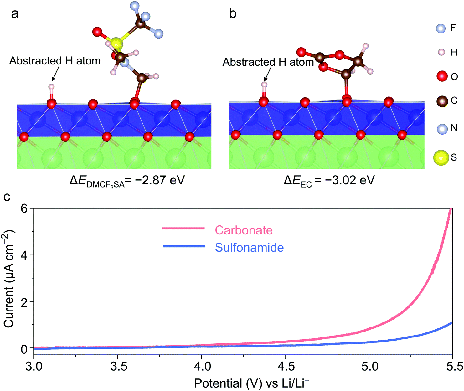 | ||
| Fig. 1 Electrolyte design and performance. Relaxed structure and reaction energy ΔE of DMCF3SA (a) and EC (b) oxidated by the highly delithiated LCO surface, as determined from DFT calculations. The reaction energies are −2.87 eV for DMCF3SA and −3.02 eV for EC, respectively. The reaction on the LCO surface includes H-abstraction and C–O bond formation between the solvent and the LCO.41,43,45 (c) Oxidation stability of different electrolytes evaluated by linear sweeping voltammetry at a scanning rate of 4 mV s−1. The sulfonamide-based and carbonate-based electrolytes are 1 m LiFSI in DMCF3SA and 1.2 M LiPF6 in EC/EMC (3:7 wt%), respectively. | ||
Three types of commercial LCO cathodes were tested. The S-LCO, A-LCO, and T-LCO denote the LCO purchased from Sigma Aldrich without any doping or coating, the one provided by Argonne National Lab, and the one purchased from Targray Co, respectively. The electrochemical performances of all Li||LCO batteries were evaluated using galvanostatic cycling with charging voltages from 4.5 VLi to 4.7 VLi at room temperature. With our sulfonamide-based electrolyte, the uncoated and undoped S-LCO exhibits significantly increased capacity retention of 91% and 79% at 4.5 VLi and 4.55 VLi, compared to 24% and 5% with the carbonate-based electrolyte after 200 cycles, respectively (Fig. S2, ESI†). It indicates that the CEI stability plays a dominant role in the capacity fading at 4.5 VLi46 rather than the bulk stability because excellent cycling stability can be achieved by choosing a more reliable electrolyte without the assistance from LCO doping or coating (Fig. S3, ESI†). We also evaluated the commercial A-LCO cathode, which should have been doped as the minor peaks47 at 4.1–4.2 VLi in the voltage profiles of the undoped S-LCO (indicated by the red circles in Fig. S2b, c, e and f, ESI†) associated with order–disorder transitions are eliminated.7 Under a charging voltage of 4.5 VLi and a discharge rate of 150 mA g−1, the Li||A-LCO cell with the carbonate-based electrolyte exhibits very low capacity retention of 7%, a low operating mid-voltage retention of ∼81.00% and an average CE of ∼99% after 200 cycles (Fig. 2a–c). The voltage profiles in Fig. S4 (ESI†) indicate obvious overpotential growth during cycling. In contrast, the 4.55 VLi cycling performance of the Li||A-LCO cell with the sulfonamide-based electrolyte is dramatically improved. The cell shows an initial capacity of 200.8 mA h g−1 with 89% and 99.74% retention of the capacity and operating mid-voltage after 200 cycles (Fig. 2a and c), respectively. An excellent average CE of ∼99.84% (Fig. 2b) suggests that the undesired side reactions between the A-LCO cathode and electrolyte are largely suppressed. Even at a higher charging voltage of 4.6 VLi, our electrolyte shows enhanced cycling stability (Fig. S5, ESI†) with a high cathode-specific Ev >3600 W h L−1. Despite the poor LMA compatibility of the carbonate-based electrolyte, under our testing conditions, including superabundant LMA and electrolyte, the LMA does not affect the cycling performance (Fig. S6, ESI†), which allows systematic comparison of all cathode performances with both electrolytes.
 | ||
| Fig. 2 Electrochemical performance of Li||LCO cells with different electrolytes. The specific capacities (a), Coulombic efficiencies (b), and operating mid-voltages (c) of Li||A-LCO cells as a function of cycle number with different electrolytes. The upper charging voltage was 4.55 VLi. The current densities during charging and discharging were 50 mA g−1 and 150 mA g−1, respectively. 10 mA g−1 charging–discharging was used for the initial 1st cycle. (d) Rate performance of Li||A-LCO cells at 4.55 VLi and corresponding voltage profiles with the sulfonamide (e) and carbonate (f) electrolytes. The unit of the current densities in (d–f) is mA g−1. (g) Cycling performance of Li||T-LCO cells and the corresponding voltage profiles (h) at a charging voltage of 4.6 VLi and current densities of 50 mA g−1 for charging and 150 mA g−1 for discharging at room temperature. 10 mA g−1 charging–discharging was used for the initial two cycles. The amounts of the sulfonamide-based and carbonate-based electrolytes were ∼15 μL and ∼50 μL per cell, respectively. 350-μm-thick Li foils were used. | ||
Besides investigating the electrolyte effect on the cycling stability, the rate performance at 4.55 VLi was also evaluated (Fig. 2d–f). The Li||A-LCO cell using the sulfonamide-based electrolyte exhibits higher reversible capacities of 197.3 mA h g−1, 196.1 mA h g−1, 191.2 mA h g−1, and 183.1 mA h g−1 compared to 184.7 mA h g−1, 160.0 mA h g−1, 137.4 mA h g−1, and 76.4 mA h g−1 with the reference electrolyte at current density of 50 mA g−1 to 300 mA g−1, respectively. The excellent rate performance at high voltages is also a good indicator of the stable CEI and LCO surface. Furthermore, another commercial T-LCO cathode was also evaluated at higher charging voltages of 4.6–4.7 VLi. Although the Li||T-LCO cells with both electrolytes reach similar high initial capacities ∼220 mA h g−1, the capacity retentions show a dramatic difference (85% vs. 57%, Fig. 2g and h). For 4.65 VLi and 4.7 VLi, the sulfonamide-based electrolyte enables high initial capacities of 227.2 mA h g−1 and 241.5 mA h g−1 with greatly improved cycling stability compared to the carbonate-based electrolyte (Fig. S7, ESI†). Furthermore, our electrolyte demonstrates excellent cycling stability (4.55 VLi, 97.6% capacity retention, CE ∼99.88% after 70 cycles, Fig. S8, ESI†) at a high temperature of 45 °C.
To shed light on the degradation mechanisms, the following investigations are focused on A-LCO cathodes after cycling at 4.55 VLi in different electrolytes. We first conducted the galvanostatic intermittent titration technique (GITT) on the Li||A-LCO cells to measure the impedance growth after cycling (Fig. 3a and b). For the reference electrolyte, severe impedance growth and huge overpotentials after 200 cycles are observed (Fig. 3b, average overpotential is 758 ± 80 mV). In comparison, for our electrolyte, the overpotentials are an order of magnitude smaller after 200 cycles (Fig. 3b, average overpotential is 15 ± 4 mV), which is consistent with the better capacity retention and rate capability reported above. Such a prominent difference in the overpotential growth by using different electrolytes can also be supported by electrochemical impedance spectroscopy (EIS) measurements. For the A-LCO with the carbonate-based electrolyte, cycling at 4.55 VLi induced a much higher charge transfer resistance (Rct) than the one cycled in the sulfonamide-based electrolyte (Fig. S9, ESI†). The continuous impedance growth hinders the bulk from achieving a high oxidation state and thus leads to a large difference in the Co oxidation states in the cycled A-LCO cathodes, which was revealed by the X-ray absorption near edge structure (XANES) mode of full-field X-ray imaging (FXI). Co oxidation states were mapped by tracking the whiteline peak positions48 of the XANES spectra acquired by scanning every pixel (∼20 × 20 nm2 area) in a 40 × 40 μm2 area of interest (Fig. 3c and d). After charging the cycled A-LCO cathodes to 4.55 VLi, higher and more uniform Co valences are noted in the one cycled with our electrolyte (Fig. 3c) than that with the carbonate-based electrolyte (Fig. 3d). This result is further confirmed by the plotted histograms of the whiteline distributions of several representative particles (Fig. 3e).
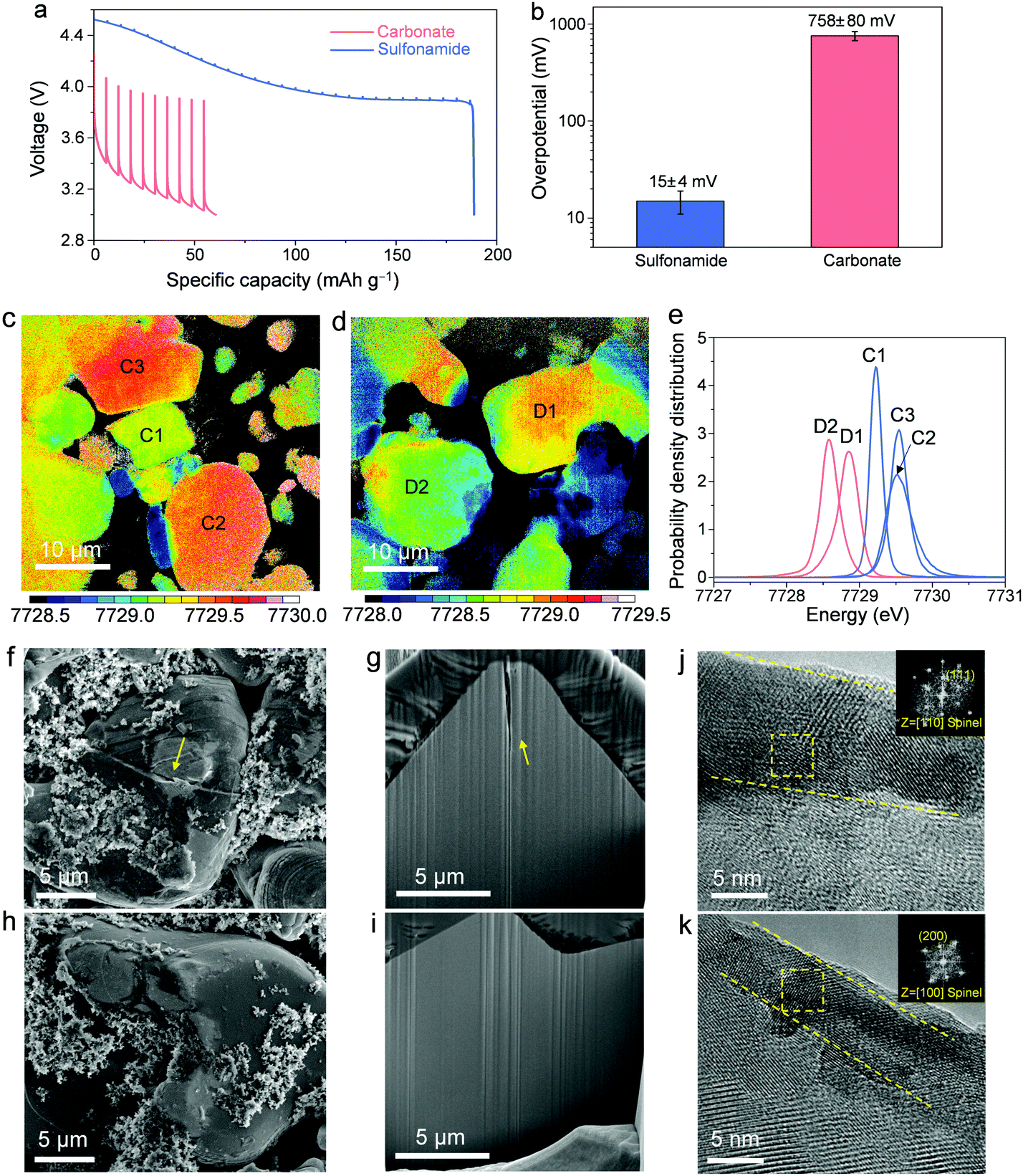 | ||
| Fig. 3 Characterization of the A-LCO cathodes cycled in different electrolytes at 4.55 V charging voltage. (a) Discharge voltage profiles from GITT plots of the cells after 200 cycles in different electrolytes. (b) Average overpotentials over different discharge states with error bars for standard deviation. XANES mapping of the A-LCO particles cycled in the sulfonamide-based (c) and carbonate-based (d) electrolytes for 100 cycles and then charged to 4.55 VLi. Statistical analysis (e) of the whiteline distributions of particles in c and d. All the C1, C2, and C3 particles with the sulfonamide-based electrolyte have higher Co oxidation states than D1 and D2 particles with the carbonate-based electrolyte. SEM images of the surfaces (f and h), the cross-sections (g and i), and HRTEM images (j and k) of A-LCO cathodes after 200 cycles in the carbonate-based (f, g and j) and sulfonamide-based (h, i and k) electrolytes. Yellow dot lines in (j and k) indicate the transformed spinel layers. Insets in (j and k) in the upper right corners are the FFT patterns from the areas indicated by the yellow squares, indicating that the transformed layers are spinel structures. | ||
We investigated the microstructure and surfaces to understand the origin of impedance growth.20 Post-cycling analysis was conducted on the surfaces and cross-sections by scanning electron microscopy (SEM, Fig. 3f–i and Fig. S10, ESI†). As highlighted by yellow arrows in Fig. 3f and g, the A-LCO cycled in the carbonate-based electrolyte shows apparent cracks in the bulk particle while the one cycled in the sulfonamide-based electrolyte keeps intact (Fig. 3h and i). This result suggests that the SCC behavior usually observed in polycrystalline NMC cathodes39 is also present in the deep-cycled LCO cathode with a single-crystalline microstructure, which is usually considered not to crack easily.49 Similar cracking behavior was previously reported in deep-cycled single-crystalline NMC50 and LCO7,24 cathodes. Considering the high catalytic capability of the LCO surface that may promote more intensive side reactions, a “good” electrolyte or proper surface modification that can passivate the surface cracks and thus suppress the SCC, is required for >4.5 VLi LCO.
Another surface degradation causing impedance growth and slow charge transfer kinetics is the surface transformation from the original layered structure to spinel phase,51 resulting from the reduction of high-valence Coα+ by electrolyte components. A visible difference in the thickness of the detrimental layers is identified by high-resolution transmission electron microscopy (HRTEM). While the resistive layer is ∼11 nm thick (Fig. 3j) for the A-LCO cycled in the carbonate-based electrolyte, it is suppressed by our sulfonamide-based electrolyte (∼5 nm thick, Fig. 3k). Fast Fourier transform (FFT) patterns in the insets of Fig. 3j and k show that the detrimental layers are spinel phases. Consistently, higher-degree cation-mixing in the bulk structure of the A-LCO cycled in the carbonate-based electrolyte is revealed by a decrease in the intensity ratio of I003/I104 in the XRD pattern compared to the one cycled in the sulfonamide-based electrolyte (Fig. S11, ESI†). These results indicate that our electrolyte greatly mitigates the surface degradation and thus suppresses the resultant impedance growth at high charging voltages, which is consistent with the improved cycling performance in Fig. 2.
The differences in the surface and interface degradation are mainly attributed to the cathode–electrolyte side reactions, as will be investigated by characterizing the side reaction byproducts in terms of gas emission, CEI, and Co dissolution. Differential electrochemical mass spectroscopy (DEMS) was carried out to monitor the gas evolution during charging to 4.7 VLi. When A-LCO is charged to above 4.5 VLi in the carbonate-based electrolyte, obvious CO2 gas begins to release (Fig. 4a), confirming the oxidation of electrolyte components. In contrast, no obvious gaseous products including CO2, O2 (Fig. 4b), or other possible gases (Fig. S12, ESI†) are detected with the sulfonamide-based electrolyte, demonstrating its excellent oxidation resistance.
 | ||
| Fig. 4 Characterization of the cathode-electrolyte side reaction and the surface chemistry of CEIs of the LCO cathodes. In situ DEMS analysis of the gas evolution during first charging in the carbonate-based (a) and sulfonamide-based (b) electrolytes. (c) Voltage profile of LCO during charging to 4.8 VLi in the sulfonamide-based electrolyte. (d) In situ FT-IR spectra on LCO surfaces upon charging to 4.8 VLi in the sulfonamide-based electrolyte. XPS spectra of the C 1s (e) and F 1s (f) for the carbon-free, binder-free LCO electrodes after charging to 4.2, 4.4, 4.5, 4.6, and 4.7 VLi with the sulfonamide-based electrolyte. | ||
In order to shed more light on the oxidation process of our sulfonamide-based electrolyte on LCO surfaces, first, in situ Fourier-transform infrared spectroscopy (FT-IR)12 was performed to characterize the evolution of CEIs during galvanostatic charging to 4.8 VLi. Upon charging LCO from open circuit potential (OCP) to 4.8 VLi (Fig. 4c), obvious changes in the IR spectra are observed from 3.9 VLi to 4.2 VLi (Fig. 4d). A peak at ∼1260 cm−1 in the S![[double bond, length as m-dash]](https://www.rsc.org/images/entities/char_e001.gif) O region, which appeared the earliest at ∼4.0 VLi, was noted. It could be attributed to the decomposition of LiFSI or DMCF3SA since they both have SO groups. Upon further charging from 4.2 VLi to 4.8 VLi, the spectra almost remain unchanged (Fig. 4d), indicating good chemical stability of the CEIs against oxidation, which can be further confirmed by the unchanged spectra acquired during holding the potential at 4.8 VLi and subsequent resting at OCP (Fig. S13, ESI†).
O region, which appeared the earliest at ∼4.0 VLi, was noted. It could be attributed to the decomposition of LiFSI or DMCF3SA since they both have SO groups. Upon further charging from 4.2 VLi to 4.8 VLi, the spectra almost remain unchanged (Fig. 4d), indicating good chemical stability of the CEIs against oxidation, which can be further confirmed by the unchanged spectra acquired during holding the potential at 4.8 VLi and subsequent resting at OCP (Fig. S13, ESI†).
Second, an ex situ X-ray photoelectron spectrometer (XPS) was used to analyze the surface chemistry of the carbon-free, binder-free electrodes at different states of charge in our sulfonamide-based electrolyte, which can avoid interference from the binder and high-surface-area conductive carbon.13 Solvent oxidation on LCO surfaces upon charging to ∼4.4 VLi is confirmed by XPS analysis of C 1s (Fig. 4e) as the peak intensities at high binding energies (i.e., corresponding to oxidized carbon such as C–O and C–SOx) increase from 4.2 VLi to 4.4 VLi, indicating the growth of surface species formed by DMCF3SA decomposition. Above 4.4 VLi, the C 1s spectra remain almost unchanged with increasing voltage, suggesting a good CEI stability at high voltages, which matches well with the FT-IR results in Fig. 4d. On the other hand, S–F species are noted from F 1s spectra (Fig. 4f) from 4.4 VLi and above, which is likely attributed to the decomposition of LiFSI salt with the S–F bond rather than the DMCF3SA solvent with the CF3 bond. The higher C–F peak intensity than the S–F one (Fig. 4f) implies that the CEIs on the LCO surface are mainly derived from the decomposition of DMCF3SA solvent rather than LiFSI salt.
In addition, the A-LCO cathodes after cycling in different electrolytes were also examined by XPS and soft X-ray absorption spectroscopy (sXAS). The CEI formed in the reference electrolyte is mainly composed of solvent decomposition products as evidenced by the C–O, CO,52,53 and CO32− species,24 while less are observed for that formed in the sulfonamide-based electrolyte (Fig. S14a, S15a and S15b, ESI†). Note that the presence of these carbon–oxygen species usually correlates with the dehydrogenation of carbonate molecules13 and the resultant formation of corrosive HF.24 A LiF-rich CEI formed in the sulfonamide-based electrolyte is also noted in the F K-edge sXAS spectra24 (Fig. S15c and d, ESI†), which is believed to be a favorable feature for enhancing the cathode stability.32,44,54 Another difference in CEI components lies in the N and S induced by the sulfonamide-based electrolyte (Fig. S16, ESI†), which is absent in the CEI formed in the carbonate-based electrolyte. Furthermore, suppressed Co dissolution by the sulfonamide-based electrolyte is revealed by the Co 2p XPS results (Fig. S14c, ESI†). It is likely that the less Co dissolution can be attributed to the formation of stable CEI, which can effectively suppress side reactions between the electrolyte and LCO and thus prevent the Co species from leaching out from the cathode. These results clearly manifest that transition-metal cation dissolution is greatly suppressed and a stable CEI is thus constructed in our sulfonamide-based electrolyte, which benefits the high-voltage electrochemical performance.
In addition to stabilizing the high-voltage LCO cathodes, it is also very important for an electrolyte to have good compatibility with the LMA to realize long-term cycling stability in Li||LCO batteries. Although our electrolyte has shown good compatibility with LMA,39 the CE evaluated by Li||Cu configuration is more appropriate to correlate with an “anode-free” scenario, which is not applicable for our Li||LCO batteries with excess Li inventory. Therefore, we adopted another well-established method55 by Li||Li configuration to evaluate the Li-metal stripping/plating CE on the Li matrix (Fig. 5a). Our sulfonamide-based electrolyte shows a much higher CE ∼99.7% and smaller overpotentials during Li plating and stripping than the carbonate-based electrolyte (CE ∼65.7%). The significant difference in CE can be mainly attributed to Li metal morphologies and SEIs formed in different electrolytes. To investigate the LMA morphology, LMAs were retrieved from the Li||A-LCO cells after 100 cycles in different electrolytes at 4.55 VLi. Dendrite-like Li deposits are seen on the LMA cycled in the carbonate-based electrolyte (Fig. 5b). Such a high-surface-area morphology can promote the harmful side reactions between the LMA and electrolyte, thus leading to poor LMA reversibility.54 In addition, an obvious Co signal from the electron dispersive spectroscopy (EDS) spectrum (Fig. 5c) is detected, which is believed to have migrated from the LCO cathode, matching well with the cathode result in Fig. S14c (ESI†). In contrast, with our sulfonamide-based electrolyte, the morphology of Li deposits tends to be large particles with less surface area (Fig. 5d) without the presence of crossover Co (Fig. 5e), which is desirable for LMA reversibility. Furthermore, we evaluated the electrolyte by an anode-free A-LCO||Cu cell under lean electrolyte conditions. Our electrolyte successfully enables capacity retention as high as 72% after 70 cycles (Fig. S17, ESI†), indicative of its excellent compatibility with both the LMA and high-voltage LCO cathode.
 | ||
| Fig. 5 Electrochemical performance and characterization of the LMAs in different electrolytes. (a) Li-metal stripping/plating CEs in the sulfonamide-based and carbonate-based electrolytes. SEM figures and corresponding elemental analysis by EDS of the LMAs extracted from the Li||A-LCO cells after 100 cycles at 4.55 VLi in the carbonate-based (b and c) and sulfonamide-based (d and e) electrolytes. XPS spectra of C K-edge (f) and F K-edge (g) of the A-LCO cathodes cycled in different electrolytes. | ||
Furthermore, to understand the effects of both electrolytes on the SEIs, surface chemistry analysis by XPS was conducted on the cycled LMAs. Since carbon-containing species are mainly derived from the electrolyte solvents, we can trace C 1s to get more information on the solvent decomposition on LMAs. The lower C 1s intensity in Fig. 5f indicates less solvent decomposition for the sulfonamide than carbonates. In addition, the F 1s XPS spectra (Fig. 5g) reveal that the LiF content in the SEI formed in the sulfonamide-based electrolyte is higher than that formed in the carbonate-based electrolyte, which can effectively stabilize the SEI.44,54 Moreover, the presence of lower-valence sulfur species (S−/S2−, Fig. S18, ESI†) could facilitate the Li+ transportation36 and lower the Li stripping/plating overpotential. These results suggest that our sulfonamide-based electrolyte successfully stabilizes the LMA-electrolyte interface and thus enables a highly reversible LMA. Finally, compared to carbonate electrolytes, the cost of the DMCF3SA solvent is still higher (Table S2, ESI†), which is expected to be greatly reduced if mass production is realized as the cost of organic solvents is highly scale-sensitive.
Conclusions
In the present work, we designed and demonstrated a sulfonamide-based electrolyte to stabilize the electrode–electrolyte interface in high-voltage Li metal||LCO batteries. The sulfonamide-based electrolyte successfully enables excellent cycling performance of commercial LCO cathodes with high capacity retentions of 89% and 85% after 200 and 100 cycles at high charging voltages of 4.55 VLi and 4.6 VLi, respectively. Our electrolyte effectively stabilizes the cathode-electrolyte interface by suppressing surface degradation, impedance growth, and side reactions in terms of gas evolution and Co dissolution. Beyond the cathode, the sulfonamide-based electrolyte also has excellent compatibility with the lithium metal anode featuring a high Li stripping/plating CE ∼99.7% due to the formation of favorable deposition morphology and stable SEI. Our work proposes a promising strategy for designing new electrolytes to realize high-voltage and high-energy Li metal||LCO batteries.Experimental section
Materials
LiCoO2 (A-LCO, the LCO powder was from BTR New Energy according to the provider) cathodes were provided by Argonne National Laboratory with ∼13 mg cm−2 active material loading. The other two types of LiCoO2 powder used in this work were purchased from Sigma Aldrich (S-LCO) and Targray. Co. Ltd (T-LCO) respectively. All the LCO powders and cathode were used without further treatment. The DMCF3SA solvent was synthesized according to our previous work.37 The LiFSI salt was provided by KISCO Co. Ltd. “m” stands for molality, mol-salt in kg-solvent (mol kg−1). Certain amounts of DMCF3SA solvent and LiFSI salt were added into a glass vial with a magnetic bar stirring for 30 min until a clear solution was obtained. All solvents needed to be purified by the 4Å molecular sieve before use. The reference carbonate electrolyte, 1.2 M and 1 M (“M”, mol-salt in L-solution, mol L−1) LiPF6 in ethylene carbonate (EC)/ethyl methyl carbonate (EMC) (3:7 wt%), were purchased from Gotion Co.
Electrochemical measurements
The S-LCO and T-LCO cathodes were fabricated by mixing LiCoO2 powder, Super C65 (conductive agent), and polyvinylidene fluoride (PVDF, binder) with a weight ratio of 94:3:3 with N-methyl-2-pyrrolidone (NMP) as solvent. Then the slurry was tape-casted by doctor blade on aluminum foil followed by vacuum drying at 120 °C overnight. The obtained electrodes were punched into disks with a diameter of 10 mm and then rolled. The active material loadings of the S-LCO and T-LCO electrodes were ∼4 and ∼11 mg cm−2, respectively. CR2032 coin cells with Li metal as an anode were used to evaluate the electrochemical performance. Electrolytes were injected by pipette to control the electrolyte amount (sulfonamide-based electrolyte: 15 μL per cell and carbonate-based electrolyte: 50 μL per cell). 350 μm-thick Li metal foils were used. The cells were tested by the galvanostatic method with different current densities on Landt CT 2001A and BTS9000 Neware cyclers. A well-established method55 was used to evaluate the Li-metal stripping/plating Coulombic efficiency. In detail, 4 mA h cm−2 Li was firstly plated onto the Cu substrate, followed by fully stripping to 1.5 VLi to remove possible oxidation layer. Subsequently, 4 mA h cm−2 Li was redeposited at 0.2 mA cm−2 as a Li reservoir, then 0.5 mA h cm−2 Li was stripped and plated at a current density of 0.5 mA cm−2 between Li and Cu for 10 cycles. After that, the remaining Li reservoir was fully stripped at 0.4 mA cm−2. The galvanostatic intermittent titration technique (GITT) was conducted to evaluate the overpotentials after cycling with current pulse intervals at 20 mA g−1 for 8 minutes and rests for 60 minutes after each pulse. Linear sweeping voltammetry (LSV) was used to measure the electrochemical stability window of the electrolytes with Li||Al (coated with Super C65 and PVDF) configuration at a scanning rate of 4 mV s−1. An anode-free cell was constructed using A-LCO as the cathode, bare Cu as an anode, and 1 m LiFSI/DMCF3SA as an electrolyte. The A-LCO cathode loading is 2.5 mA h cm−2, and the electrolyte/capacity ratio (E/C ratio) is 3.2 g A h−1. The cell was tested by a galvanostatic method with C/5 charging and C/2 discharging (C/10 charging–discharging for the initial 3 cycles) between 3 and 4.5 V at room temperature.
Characterization
The cycled Li||LCO cells with different electrolytes were disassembled in a glovebox filled with Ar, followed by washing with dimethyl ether (DME, for Li anode) and dimethyl carbonate (DMC, for LCO cathodes) three times to remove residual lithium salts. Scanning electron microscopy (SEM, Zeiss Merlin) coupled with energy-dispersive spectroscopy (EDS) was performed to examine the surface morphology and identify the elemental compositions. Focused ion beam (FIB, NVision 40 CrossBeam, ZEISS Co.) was used to prepare thin slices for transmission electron microscopy (TEM) and cross-sectional SEM observations. In situ differential electrochemistry mass spectrometry (DEMS) was conducted to detect the gas species during cell operation. Ex situ transmission X-ray microscopy X-ray absorption near-edge structure (TXM XANES) was performed to map the Co oxidation states of the LCO electrodes cycled in different electrolytes after charging to 4.55 VLi at the full-field X-ray imaging (FXI) beamline at NSLS II of Brookhaven National Laboratory. The TXM results were analyzed by a whiteline peak position tracking method.48 Soft X-ray absorption spectroscopy (sXAS) measurements in total electron yield (TEY) and partial fluorescence yield (PFY) detection modes were conducted at the IOS beamline (23-ID-2) of the National Synchrotron Light Source II (NSLS-II), Brookhaven National Laboratory. Samples at discharged states were mounted on a sample plate using carbon tape and loaded into the ultrahigh vacuum (UHV) chamber before measurement. PFY spectra were measured using a Vortex EM silicon drift detector. X-ray diffraction (XRD, Rigaku SmartLab) was conducted on pristine and cycled LCO cathodes for phase identification and peak intensity ratios were calculated by the ratio of peak areas after background subtraction. In situ Fourier-transform infrared spectroscopy (FT-IR) was performed by a specially designed electrochemical cell to characterize the evolution of CEIs during galvanostatic charging to 4.8 VLi at a current density of 25 mA g−1. More details about in situ FT-IR can be found in our previous work.12 FT-IR spectra were also acquired at regular intervals during holding the potential at 4.8 VLi and subsequent resting at open circuit potential. An ex situ X-ray photoelectron spectrometer (XPS, Physical Electronics Versaprobe II) was used to analyze the surface chemistry of the cycled electrodes and carbon-free, binder-free electrodes at different states of charge. Samples were transferred by a specially designed transfer vessel to avoid any contact with air. The carbon-free, binder-free electrodes were fabricated by mixing LCO powder with NMP in a 1:50 mass ratio. The slurry was cast on a piece of aluminum foil followed by vacuum drying at 120 °C overnight. The obtained LCO electrodes were then roll-pressed and punched. Half cells were assembled with the carbon-free, binder-free electrodes and were then charged to 4.2, 4.4, 4.5, 4.6, and 4.7 VLi at a rate of 1/20 C. Ex situ XPS spectra on carbon-free and binder-free electrodes were normalized for comparison.
First-principles calculations
DFT, as implemented in the VASP package56 was employed in this study, with the projector augmented wave method57 and Perdew–Burke–Ernzerhof58 exchange–correlation functional. The energy cutoff used is 500 eV, and a 1 × 1 × 1 Monkhorst–Pack59k-point sampling is adopted. We took the literature values44 (Ueff = 6.7 eV and J = 1 eV) for the DFT+U treatment of Co 3d orbitals. DFT-D3 correction60 was also used to account for the van der Waals effect. To simulate the LCO surface, a 4 × 4 × 1 slab with 20 Å vacuum was built, and atoms in the bottom 4.8 Å were kept immobile during ionic relaxations. The reaction on the LCO surface includes H-abstraction and C–O bond formation between the solvent and the LCO. The overall reaction energy (ΔE) was therefore computed as the difference between the energy of the eventual adsorbate-LCO system (Eadsorbed) and the sum of independent solvent molecule (Esolvent) and a clean LCO substrate (Esubtrate): ΔE ≡ Eadsorbed − (Esolvent + Esubtrate). Here, a less negative value implies higher oxidation resistance of the solvent molecule.Conflicts of interest
There are no conflicts to declare.Acknowledgements
J. L. acknowledges support by Honda Research Institute and NSF CBET-2034902. The authors acknowledge the cathodes provided by US DOE CAMP Facility, Argonne National Laboratory, and LiFSI salt by KISCO Co. Ltd. This work made use of the MRSEC Shared Experimental Facilities supported by the National Science Foundation under award number DMR-1419807. This work used resources of the beamlines FXI (18-ID) and IOS (23-ID-2) of the National Synchrotron Light Source II, a U.S. Department of Energy (DOE) Office of Science User Facility operated for the DOE Office of Science by Brookhaven National Laboratory under Contract No. DE-SC0012704.References
- R. Schmuch, R. Wagner, G. Hörpel, T. Placke and M. Winter, Nat. Energy, 2018, 3, 267–278 CrossRef CAS.
- W. Xue, Z. Shi, L. Suo, C. Wang, Z. Wang, H. Wang, K. P. So, A. Maurano, D. Yu, Y. Chen, L. Qie, Z. Zhu, G. Xu, J. Kong and J. Li, Nat. Energy, 2019, 4, 374–382 CrossRef CAS.
- W. Xue, L. Miao, L. Qie, C. Wang, S. Li, J. Wang and J. Li, Curr. Opin. Electrochem., 2017, 6, 92–99 CrossRef CAS.
- J. Liu, Z. Bao, Y. Cui, E. J. Dufek, J. B. Goodenough, P. Khalifah, Q. Li, B. Y. Liaw, P. Liu, A. Manthiram, Y. S. Meng, V. R. Subramanian, M. F. Toney, V. V. Viswanathan, M. S. Whittingham, J. Xiao, W. Xu, J. Yang, X.-Q. Yang and J.-G. Zhang, Nat. Energy, 2019, 4, 180–186 CrossRef CAS.
- S. Kalluri, M. Yoon, M. Jo, S. Park, S. Myeong, J. Kim, S. X. Dou, Z. Guo and J. Cho, Adv. Energy Mater., 2017, 7, 1601507 CrossRef.
- X. Wang, X. Wang and Y. Lu, Ind. Eng. Chem. Res., 2019, 58, 10119–10139 CrossRef CAS.
- Q. Liu, X. Su, D. Lei, Y. Qin, J. Wen, F. Guo, Y. A. Wu, Y. Rong, R. Kou, X. Xiao, F. Aguesse, J. Bareño, Y. Ren, W. Lu and Y. Li, Nat. Energy, 2018, 3, 936–943 CrossRef CAS.
- Y. Huang, Y. Zhu, H. Fu, M. Ou, C. Hu, S. Yu, Z. Hu, C.-T. Chen, G. Jiang, H. Gu, H. Lin, W. Luo and Y. Huang, Angew. Chem., Int. Ed., 2020, 60, 4682–4688 CrossRef PubMed.
- Z. Zhu, D. Yu, Z. Shi, R. Gao, X. Xiao, I. Waluyo, M. Ge, Y. Dong, W. Xue, G. Xu, W.-K. Lee, A. Hunt and J. Li, Energy Environ. Sci., 2020, 13, 1865–1878 RSC.
- Z. Zhu, D. Yu, Y. Yang, C. Su, Y. Huang, Y. Dong, I. Waluyo, B. Wang, A. Hunt and X. Yao, Nat. Energy, 2019, 4, 1049–1058 CrossRef CAS.
- J. G. Han, K. Kim, Y. Lee and N. S. Choi, Adv. Mater., 2019, 31, e1804822 CrossRef PubMed.
- Y. Zhang, Y. Katayama, R. Tatara, L. Giordano, Y. Yu, D. Fraggedakis, J. G. Sun, F. Maglia, R. Jung and M. Z. Bazant, Energy Environ. Sci., 2020, 13, 183–199 RSC.
- Y. Yu, P. Karayaylali, Y. Katayama, L. Giordano, M. Gauthier, F. Maglia, R. Jung, I. Lund and Y. Shao-Horn, J. Phys. Chem. C, 2018, 122, 27368–27382 CrossRef CAS.
- M. Gauthier, T. J. Carney, A. Grimaud, L. Giordano, N. Pour, H. H. Chang, D. P. Fenning, S. F. Lux, O. Paschos, C. Bauer, F. Maglia, S. Lupart, P. Lamp and Y. Shao-Horn, J. Phys. Chem. Lett., 2015, 6, 4653–4672 CrossRef CAS PubMed.
- J. Qian, L. Liu, J. Yang, S. Li, X. Wang, H. L. Zhuang and Y. Lu, Nat. Commun., 2018, 9, 4918 CrossRef PubMed.
- K. Wang, J. Wan, Y. Xiang, J. Zhu, Q. Leng, M. Wang, L. Xu and Y. Yang, J. Power Sources, 2020, 460, 228062 CrossRef CAS.
- Z. Zhu, H. Wang, Y. Li, R. Gao, X. Xiao, Q. Yu, C. Wang, I. Waluyo, J. Ding, A. Hunt and J. Li, Adv. Mater., 2020, 32, 2005182 CrossRef CAS PubMed.
- J.-N. Zhang, Q. Li, C. Ouyang, X. Yu, M. Ge, X. Huang, E. Hu, C. Ma, S. Li, R. Xiao, W. Yang, Y. Chu, Y. Liu, H. Yu, X.-Q. Yang, X. Huang, L. Chen and H. Li, Nat. Energy, 2019, 4, 594–603 CrossRef CAS.
- X. Yang, M. Lin, G. Zheng, J. Wu, X. Wang, F. Ren, W. Zhang, Y. Liao, W. Zhao, Z. Zhang, N. Xu, W. Yang and Y. Yang, Adv. Funct. Mater., 2020, 30, 2004664 CrossRef CAS.
- M. Yoon, Y. Dong, Y. Yoo, S. Myeong, J. Hwang, J. Kim, S. H. Choi, J. Sung, S. J. Kang, J. Li and J. Cho, Adv. Funct. Mater., 2019, 30, 1907903 CrossRef.
- Z. Li, A. Li, H. Zhang, F. Ning, W. Li, A. Zangiabadi, Q. Cheng, J. J. Borovilas, Y. Chen, H. Zhang, X. Xiao, C. Ouyang, X. Huang, W.-K. Lee, M. Ge, Y. S. Chu, X. Chuan and Y. Yang, Energy Storage Mater., 2020, 29, 71–77 CrossRef.
- K. Nie, X. Sun, J. Wang, Y. Wang, W. Qi, D. Xiao, J.-N. Zhang, R. Xiao, X. Yu, H. Li, X. Huang and L. Chen, J. Power Sources, 2020, 470, 228423 CrossRef CAS.
- Y. Wang, Q. Zhang, Z. C. Xue, L. Yang, J. Wang, F. Meng, Q. Li, H. Pan, J. N. Zhang, Z. Jiang, W. Yang, X. Yu, L. Gu and H. Li, Adv. Energy Mater., 2020, 10, 2001413 CrossRef CAS.
- X. Ren, X. Zhang, Z. Shadike, L. Zou, H. Jia, X. Cao, M. H. Engelhard, B. E. Matthews, C. Wang, B. W. Arey, X. Q. Yang, J. Liu, J. G. Zhang and W. Xu, Adv. Mater., 2020, 32, 2004898 CrossRef CAS PubMed.
- S. Lin and J. Zhao, ACS Appl. Mater. Interfaces, 2020, 12, 8316–8323 CrossRef CAS PubMed.
- T. Dong, J. Zhang, G. Xu, J. Chai, H. Du, L. Wang, H. Wen, X. Zang, A. Du, Q. Jia, X. Zhou and G. Cui, Energy Environ. Sci., 2018, 11, 1197–1203 RSC.
- M. Zhang, J. Zhang, J. Yang, X. Du, Z. Chen, K. Chen, C. Lu, H. Zhang, T. Dong, J. Li, Z. Zhang, H. Zhang and G. Cui, J. Electrochem. Soc., 2019, 166, A2313–A2321 CrossRef CAS.
- M. Zhao, X. Zuo, X. Ma, X. Xiao, L. Yu and J. Nan, J. Power Sources, 2016, 323, 29–36 CrossRef CAS.
- C. Pang, G. Xu, W. An, G. Ding, X. Liu, J. Chai, J. Ma, H. Liu and G. Cui, Energy Technol., 2017, 5, 1979–1989 CrossRef CAS.
- L. Wang, B. Chen, J. Ma, G. Cui and L. Chen, Chem. Soc. Rev., 2018, 47, 6505–6602 RSC.
- H. Sun, G. Zhu, Y. Zhu, M. C. Lin, H. Chen, Y. Y. Li, W. H. Hung, B. Zhou, X. Wang, Y. Bai, M. Gu, C. L. Huang, H. C. Tai, X. Xu, M. Angell, J. J. Shyue and H. Dai, Adv. Mater., 2020, 32, 2001741 CrossRef CAS PubMed.
- T. Li, X.-Q. Zhang, P. Shi and Q. Zhang, Joule, 2019, 3, 2647–2661 CrossRef CAS.
- Z. Yu, H. Wang, X. Kong, W. Huang, Y. Tsao, D. G. Mackanic, K. Wang, X. Wang, W. Huang, S. Choudhury, Y. Zheng, C. V. Amanchukwu, S. T. Hung, Y. Ma, E. G. Lomeli, J. Qin, Y. Cui and Z. Bao, Nat. Energy, 2020, 5, 526–533 CrossRef CAS.
- R. Weber, M. Genovese, A. J. Louli, S. Hames, C. Martin, I. G. Hill and J. R. Dahn, Nat. Energy, 2019, 4, 683–689 CrossRef CAS.
- H. Yang, J. Li, Z. Sun, R. Fang, D.-W. Wang, K. He, H.-M. Cheng and F. Li, Energy Storage Mater., 2020, 30, 113–129 CrossRef.
- W. Xue, Z. Shi, M. Huang, S. Feng, C. Wang, F. Wang, J. Lopez, B. Qiao, G. Xu, W. Zhang, Y. Dong, R. Gao, Y. Shao-Horn, J. A. Johnson and J. Li, Energy Environ. Sci., 2020, 13, 212–220 RSC.
- S. Feng, M. Huang, J. R. Lamb, W. Zhang, R. Tatara, Y. Zhang, Y. Guang Zhu, C. F. Perkinson, J. A. Johnson and Y. Shao-Horn, Chem, 2019, 5, 2630–2641 CAS.
- A. Shyamsunder, W. Beichel, P. Klose, Q. Pang, H. Scherer, A. Hoffmann, G. K. Murphy, I. Krossing and L. F. Nazar, Angew. Chem., Int. Ed., 2017, 56, 6192–6197 CrossRef CAS PubMed.
- W. Xue, M. Huang, Y. Li, Y. G. Zhu, R. Gao, X. Xiao, W. Zhang, S. Li, G. Xu and Y. Yu, Nat. Energy, 2021, 6, 495–505 CrossRef CAS.
- L. Giordano, P. Karayaylali, Y. Yu, Y. Katayama, F. Maglia, S. Lux and Y. Shao-Horn, J. Phys. Chem. Lett., 2017, 8, 3881–3887 CrossRef CAS PubMed.
- L. Giordano, T. M. Østergaard, S. Muy, Y. Yu, N. Charles, S. Kim, Y. Zhang, F. Maglia, R. Jung and I. Lund, Chem. Mater., 2019, 31, 5464–5474 CrossRef CAS.
- E. Trevisanello, R. Ruess, G. Conforto, F. H. Richter and J. Janek, Adv. Energy Mater., 2021, 11, 2003400 CrossRef CAS.
- L. Giordano, P. Karayaylali, Y. Yu, Y. Katayama, F. Maglia, S. Lux and Y. Shao-Horn, J. Phys. Chem. Lett., 2017, 8, 3881–3887 CrossRef CAS PubMed.
- X. Fan, L. Chen, O. Borodin, X. Ji, J. Chen, S. Hou, T. Deng, J. Zheng, C. Yang, S.-C. Liou, K. Amine, K. Xu and C. Wang, Nat. Nanotechnol., 2018, 13, 715–722 CrossRef CAS PubMed.
- T. M. Østergaard, L. Giordano, I. E. Castelli, F. Maglia, B. K. Antonopoulos, Y. Shao-Horn and J. Rossmeisl, J. Phys. Chem. C, 2018, 122, 10442–10449 CrossRef.
- Z. Chen and J. R. Dahn, Electrochem. Solid-State Lett., 2004, 7, A11 CrossRef CAS.
- J. Li, C. Lin, M. Weng, Y. Qiu, P. Chen, K. Yang, W. Huang, Y. Hong, J. Li, M. Zhang, C. Dong, W. Zhao, Z. Xu, X. Wang, K. Xu, J. Sun and F. Pan, Nat. Nanotechnol., 2021, 16, 599–605 CrossRef CAS PubMed.
- M. Wolf, B. M. May and J. Cabana, Chem. Mater., 2017, 29, 3347–3362 CrossRef CAS.
- Y. Wang, E. Wang, X. Zhang and H. Yu, Energy Fuels, 2021, 35, 1918–1932 CrossRef CAS.
- F. Zhang, S. Lou, S. Li, Z. Yu, Q. Liu, A. Dai, C. Cao, M. F. Toney, M. Ge, X. Xiao, W. K. Lee, Y. Yao, J. Deng, T. Liu, Y. Tang, G. Yin, J. Lu, D. Su and J. Wang, Nat. Commun., 2020, 11, 3050 CrossRef CAS PubMed.
- A. Yano, M. Shikano, A. Ueda, H. Sakaebe and Z. Ogumi, J. Electrochem. Soc., 2016, 164, A6116–A6122 CrossRef.
- X. Ren, L. Zou, X. Cao, M. H. Engelhard, W. Liu, S. D. Burton, H. Lee, C. Niu, B. E. Matthews, Z. Zhu, C. Wang, B. W. Arey, J. Xiao, J. Liu, J.-G. Zhang and W. Xu, Joule, 2019, 3, 1662–1676 CrossRef CAS.
- X. Cao, X. Ren, L. Zou, M. H. Engelhard, W. Huang, H. Wang, B. E. Matthews, H. Lee, C. Niu, B. W. Arey, Y. Cui, C. Wang, J. Xiao, J. Liu, W. Xu and J.-G. Zhang, Nat. Energy, 2019, 4, 796–805 CrossRef CAS.
- L. Suo, W. Xue, M. Gobet, S. G. Greenbaum, C. Wang, Y. Chen, W. Yang, Y. Li and J. Li, Proc. Natl. Acad. Sci. U. S. A., 2018, 115, 1156–1161 CrossRef CAS PubMed.
- B. D. Adams, J. Zheng, X. Ren, W. Xu and J.-G. Zhang, Adv. Energy Mater., 2017, 8, 1702097 CrossRef.
- G. Kresse and J. Furthmüller, Phys. Rev. B: Condens. Matter Mater. Phys., 1996, 54, 11169 CrossRef CAS PubMed.
- P. E. Blöchl, Phys. Rev. B: Condens. Matter Mater. Phys., 1994, 50, 17953 CrossRef PubMed.
- J. P. Perdew, K. Burke and M. Ernzerhof, Phys. Rev. Lett., 1996, 77, 3865 CrossRef CAS PubMed.
- H. J. Monkhorst and J. D. Pack, Phys. Rev. B: Solid State, 1976, 13, 5188 CrossRef.
- S. Grimme, J. Antony, S. Ehrlich and H. Krieg, J. Chem. Phys., 2010, 132, 154104 CrossRef PubMed.
Footnotes |
| † Electronic supplementary information (ESI) available. See DOI: 10.1039/d1ee01265g |
| ‡ These authors contributed equally to this work. |
| This journal is © The Royal Society of Chemistry 2021 |