
Graphene oxide fibers by microfluidics assembly: a strategy for structural and dimensional control†
Jaqueline F.
Rocha
 ab,
Leandro
Hostert
a,
Martha Lucia M.
Bejarano
b,
Roberta M.
Cardoso
b,
Matheus D.
Santos
a,
Camila M.
Maroneze
a,
Mario R.
Gongora-Rubio
b and
Cecilia de Carvalho Castro
Silva
*a
ab,
Leandro
Hostert
a,
Martha Lucia M.
Bejarano
b,
Roberta M.
Cardoso
b,
Matheus D.
Santos
a,
Camila M.
Maroneze
a,
Mario R.
Gongora-Rubio
b and
Cecilia de Carvalho Castro
Silva
*a
aMackGraphe – Graphene and Nanomaterials Research Center, Mackenzie Presbyterian University, 01302-907, São Paulo, Brazil. E-mail: cecilia.silva@mackenzie.br
bMicromanufacturing Laboratory – Bionanomanufacturing Center – Institute for Technological Research, 05508-901, São Paulo, Brazil
First published on 10th March 2021
Abstract
Graphene oxide (GO) microfibers with controlled and homogeneous shapes and tunable diameters were fabricated using the 3 dimensional (3D) hydrodynamic focusing concept on a microfluidic device. Thermal and microwave treatments are used to obtain reduced graphene oxide (rGO) microfibers with outstanding electrical properties, thus enabling the development of ionic liquid-gate field-effect transistors (FET) based on graphene derivative microfibers.
Graphene derivatives have been investigated as building blocks for the fabrication of multifunctional fibers due to their outstanding properties, such as high surface area, and excellent electrical, optical, and mechanical properties.1–3 These fibers have been explored in the development of implantable electrodes for neural recording activity,4 flexible energy storage devices,5,6 connector wires,7 actuators8 and textile-based electronic materials.9,10 Several approaches for the assembly of graphene oxide (GO) nanosheets into fiber structures have been described, such as wet-spinning,11,12 dry spinning,13 electrophoretic assembly,14 and film conversion.15 However, many challenges still remain in the control of the dimensions and morphology of the resulting fibers, highlighting the homogeneity and the alignment of the GO sheets along the main axis of the fiber. For example, by the traditional wet-spinning approach the tuneable diameter of the GO fibers is limited to the size of the spinneret nozzle or the concentration of the GO dispersion.7,12 This increases the cost of production and also introduces a number of limitations, such as the use of GO sheets with reduced lateral dimensions to avoid the clogging of the nozzles in the spinneret with smaller sizes, which results in the worsening of the mechanical, electrical and thermal properties of the graphene derivative fiber.16,17 Recently, microfluidic spinning has emerged as an efficient strategy for preparing graphene microfibers with outstanding properties and tunable microstructures.9,18
Here, we demonstrate the use of the 3D hydrodynamic focusing concept on a microfluidic device to achieve the high alignment of the GO sheets during microfiber formation and to obtain GO microfibers with controlled and homogeneous shapes and tunable diameters. A strong correlation between the fiber diameter and the flow rate ratio between the GO dispersion (core fluid) and coagulant solution (sheath fluid) is established, allowing us to obtain graphene derivative fibers with fine control of the diameter. Thermal and microwave treatments are used to obtain reduced graphene oxide (rGO) microfibers with outstanding electrical properties, which enables the development of ionic liquid-gate field-effect transistors (FET) based on graphene derivative microfibers.
Fig. 1 shows the developed 3D hydrodynamic flow focusing microfluidic (3DHFFM) device (Fig. 1(a)), a scheme of the fabrication process of the GO microfibers (Fig. 1(b)) and scanning electron microscopy (SEM) images of the obtained GO fibers (Fig. 1(d–f)). The 3DHFFM device has been fabricated based on the low temperature co-fired ceramics (LTCC) technology (ESI Text 1†). The device displays two rectangular shape channels, one of them with a perpendicular lateral entrance in the shape of an arc that favours the distribution of the sheath fluid (coagulant agent). The detailed geometry of the 3DHFFM devices is shown in Fig. S1(a and b).†
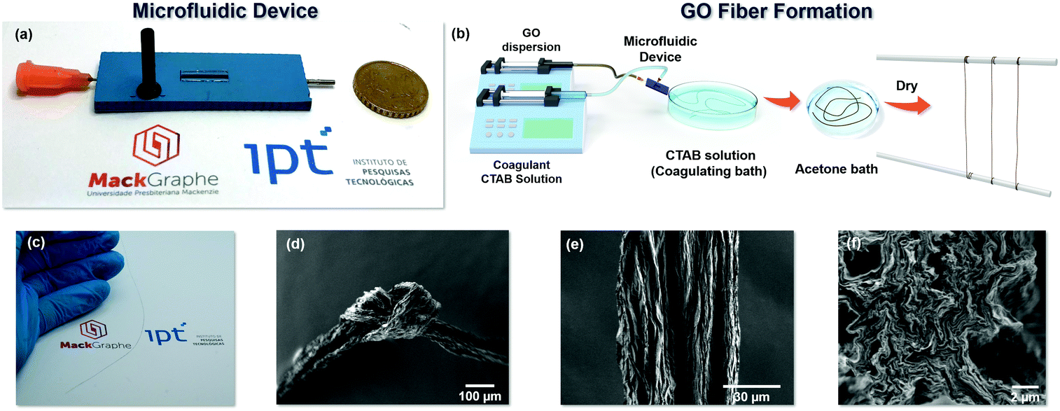 | ||
| Fig. 1 (a) Photograph of the 3D hydrodynamic flow focusing microfluidic (3DHFFM) device fabricated to obtain the GO microfibers. (b) Illustration GO microfiber formation. (c) Photograph of the GO microfiber. SEM images of the GO microfibers (d) with an overhand knot, and (e) of the surface and (f) cross section. The GO microfibers are flexible, and their surfaces are not smooth, with many dentate-bends. | ||
Firstly, an aqueous solution of hexadecyl(trimethyl)ammonium bromide (CTAB) (coagulant solution) was injected, as the outer fluid, at 3.0 mL min−1 in the rectangular channel using one side sheath flow for flow focusing of the microfluidic device, and a GO dispersion was injected in the inner region of the rectangular channel of the device at 1.5 mL min−1 (Fig. S1(a)†). The positive charge of the CTAB (surfactant) strongly interacts with the negatively charged oxygen functional groups of the GO sheets, neutralizing the electrostatic repulsion between the GO sheets, inducing their assembly in a neat way.12 The mechanism of GO microfiber formation inside of the 3DHFFM device was investigated by computational fluid dynamics (CFD) simulation.
Fig. S4 and ESI Video 1† show streamlines colored by the velocity magnitude for CTAB solution and the GO dispersion (in brown) in the 3DHFFM device. The velocity profiles show the direction and magnitude of the core and sheath flow in different locations of the 3DHFFM device. The CFD results showed that the 3DHFFM device is very efficient for fluid handling on microscopic scales and to produce the GO microfibers, applying the hydrodynamic focusing technique in a rectangular channel. This process is favored by the 3D hydrodynamic focusing effect because the GO fluid is homogeneously surrounded by the CTAB solution.
The uniformity of the fluid velocity of the CTAB solution around the GO dispersion enables a higher control in the interaction at the CTAB and GO interface, ensuring the formation of a homogeneous and cylindrical fiber, even using a microfluidic device with a rectangular shape. In addition, the coaxial shear flow that occurs at the interface between GO and CTAB fluids forces GO sheets to achieve high regularity and alignment in the axis direction. The images shown in Fig. 1(c–f) reinforce the results obtained with the CFD simulation (Fig. S4†). The GO microfibers with long length and flexible properties are shown in Fig. 1(c) and Fig. S5.† The 3DHFFM device allows the formation of the GO microfibers in a continuous way, limiting the length of these by the dimensions of the collector coagulant bath used, which can also be replaced with an automated roller. The GO microfibers are flexible enough to make a compact knot, as observed in the scanning microscopy image (SEM) in Fig. 1(d). The GO microfibers have a homogeneous structure, as seen in SEM images obtained in low magnification (100×) of different GO microfibers (Fig. S6(a(i–iii)).† The SEM image (Fig. 1e) shows the high-order alignment of the densely stacked GO sheets along the main axis, which can also be observed in the cross section SEM images in higher (Fig. 1f) and lower magnification (Fig. S6(a-iv))†, revealing also that the GO microfiber has a circular shape. The wrinkled surface (Fig. 1e) and the dentate-bends observed in the GO microfiber cross section (Fig. 1f and Fig. S6(a-iv)†) results from the large GO sheet size (Fig. S2(b)†) that must take the folded structure to facilitate liquid evaporation.16
Furthermore, we demonstrate by the use of the 3DHFFM device the control of the GO fiber diameter by varying the flow-rate ratio of the CTAB solution (QCTAB) and GO dispersion (QGO), which is expressed by: R = (QCTAB/QGO). Keeping the QGO constant at 1.5 mL min−1, the values of R were studied in a range of 2–8.7.
The SEM images in Fig. 2a(i–v) and the CFD simulation, showing the streamlines colored by velocity magnitude for CTAB solution (phase 1) and the GO dispersion (brown) along the cross-section of the coaxial flow (Fig. 2b(i–v), clearly indicate that the flow rate ratio significantly affects the diameter of the GO microfibers. By increasing the R values from 2 to 8.7, the diameter of the GO microfibers decays exponentially, as can be seen in Fig. 2(c) and expressed by the fitting equations:
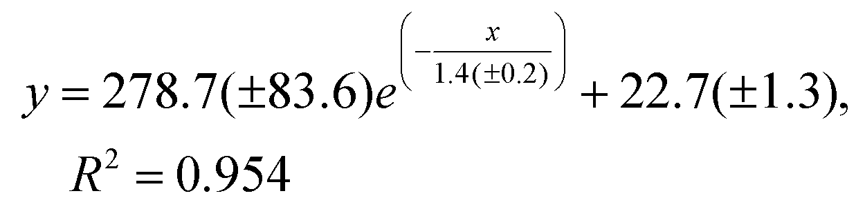 | (1) |
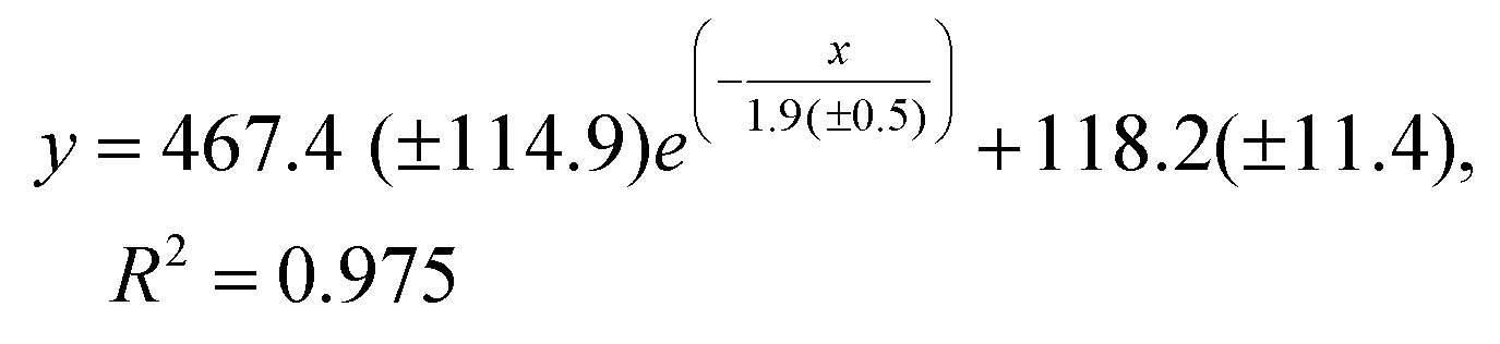 | (2) |
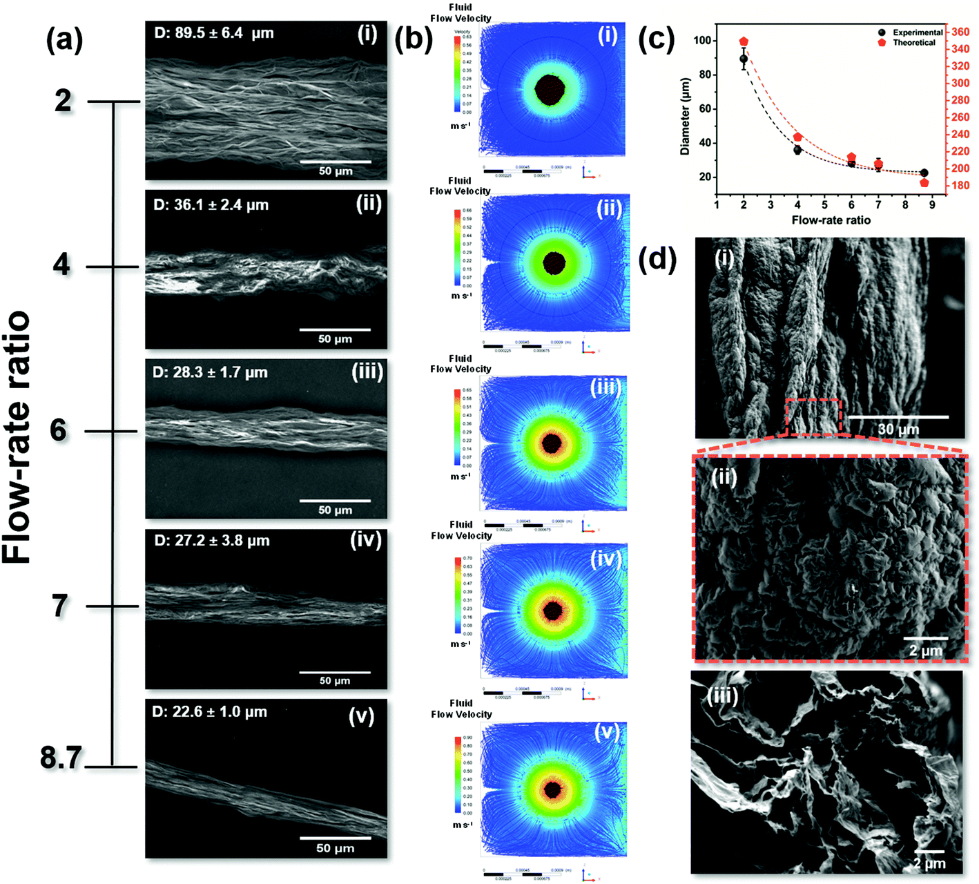 | ||
| Fig. 2 (a–c) Influence of the flow rate ratio on the diameter of the GO microfibers. SEM image (a) and cross-section image of the coaxial flow showing the streamlines colored by velocity magnitude for CTAB solution (phase 1) and the GO dispersion (brown) obtained by CFD simulations (b) as a function of flow rate ratio for R = 2 (i), 4 (ii), 6 (iii), 7 (iv) and 8.7. (c) Graphical representation of the correlation between the experimental and theoretical diameters of the GO microfiber as a function of the flow rate ratio. (d) SEM images of the surface morphology (i and ii) and cross-section (iii) of the MW rGO microfibers. | ||
From the analysis of Fig. 2(c), it is possible to observe that the diameter of the GO microfibers estimated by the CFD simulations for different R conditions is higher than that obtained experimentally (by the SEM inspection of the GO microfibers, Fig. 2(a)). This is related to the drying process of the GO microfibers. After being removed from the coagulation bath, the GO fibers are dried and compact microstructures are formed by capillary shrinkage forces.1
It has already been reported that the diameter of GO microfibers obtained by wet-spinning and microfluidic spinning approaches shrank to 1/10 to 1/3 that of the original GO fiber, indicating that 67–90% of the volume of the gel-state fiber was occupied by the coagulant and/or the remaining solvent.3 The diameter reduction (%) of the GO microfibers obtained using the 3DHFFM device as well as the theoretical simulation are shown in Fig. S7,† in which a good correlation is clearly observed. Using the fitting equations from Fig. 2(c) and Fig. S7† is possible to predict and tune the diameter and diameter reduction (%) of the GO microfibers obtained using the 3DHFFM device. These insights open opportunities to design GO microfibers with controlled diameter and shape and to define the set of boundary conditions where the 3DHFFM device can operate to produce microfibers in a large-scale approach.
The GO microfibers were reduced by thermal and microwave (MW) treatment. Fig. 2(d) shows the morphological features of the reduced graphene oxide fibers (rGO) after the MW treatment (MW rGO microfibers). The MW rGO microfiber shows an increase in diameter (Fig. 2(di)) when compared with the GO and rGO microfibers (Fig. S8†) and an expressive change in the surface morphology (Fig. 2(dii)), presenting a crumpled surface. The MW treatment promotes the heating of the rGO sheets to several thousands of degrees celsius in only a few tens of ms,22 which induces the expansion and folding of the rGO sheets, creating a hollow interior in the microfiber, due to the fast removal of the oxygen functional groups. Fig. 2(diii) presents a high magnification SEM cross-section image, showing that the MW rGO nanosheets expanded and aligned along the microfiber direction. In addition, in Fig. S6(civ)† it is possible to see the well-defined hollow structure of the MW rGO microfiber. The hollow structure is observed after the MW treatment, and this feature is not observed in the GO (Fig. S6(aiv)†) and rGO (Fig. S6(biv)†) microfibers.
The effect of microwave treatment on the rGO microfiber features was investigated by Raman spectroscopy. Fig. 3(a) shows representative Raman spectra for the GO, rGO and MW rGO microfibers. The classical Raman features for graphene derivatives consist of a D peak at ∼1350 cm−1 resulting from the sp3 carbons from defects (the D band does not appear in high quality graphene), a G peak at ∼1580 cm−1 attributed to the sp2 carbons (refers to the stretching of the C–C bonds) and a 2D peak at ∼2700 cm−1 that is the second order mode of the D band, which is directly related to the structural organization in the two-dimensional plane of graphene.23 After the MW treatment the Raman spectrum of the MW rGO microfiber exhibits sharp and symmetrical 2D and G peaks and a nearly absent D peak, indicating a high crystallinity of the material. The intensity of the D band is usually used to estimate the degree of structural disorder in the carbon samples.24 Therefore, the intensity ratio between the D and G bands (ID/IG) was estimated for the GO (1.01 ± 0.40), rGO (1.14 ± 0.05) and MW rGO (0.09 ± 0.01) microfibers, indicating the restructuring of the sp2 carbon crystalline domains for the MW rGO microfibers. The size of the crystalline domains, La, for the MW rGO microfibers was also estimated (see the ESI†), achieving high La values of 217.86 ± 12.11 nm, which is compatible with graphene obtained by the chemical vapor deposition (CVD) process.25 The full width at half maximum (FWHM) of the 2D band for the MW rGO microfiber (44.01 ± 6.62 cm−1) is much smaller than that in the case of randomly stacked single-layer graphene (∼50 cm−1).26 This feature is due the expansion and folding of the rGO sheets in the microfiber during the MW treatment, as can be seen in the Fig. 2(d-iii). The MW treatment is reproducible, and Fig. S9† shows the Raman spectra obtained for ten different MW rGO microfibers, presenting similar Raman features, and it proved to be a simple and efficient approach for the reduction of GO, restoring the crystallinity of the nanosheets and significantly increasing the size of sp2 C domains.22 The chemical composition of the graphene derivative fibers and the effectiveness of the reduction process were also evaluated by Fourier-transform infrared spectroscopy (ESI and Fig. S10†), where it was possible to observe the complete removal of the CTAB residues and oxygen functional groups from GO after the thermal and MW treatment.
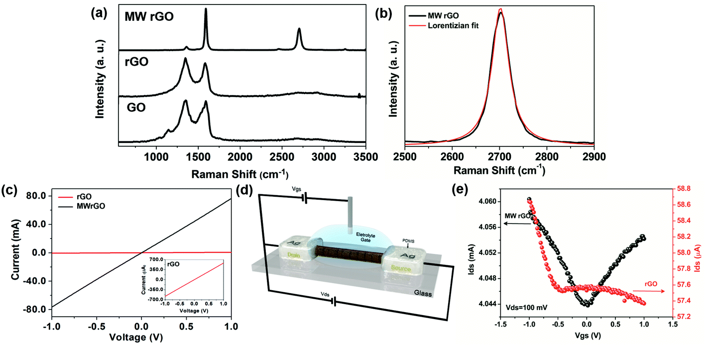 | ||
| Fig. 3 (a) Representative Raman spectra for the GO, rGO and MW rGO microfibers. (b) 2D band of MW-rGO with its respective Lorentzian fit, with a FWHM of 44.01 ± 6.62 cm−1. (c) Current vs. voltage curve for the rGO and MW rGO microfibers. (d) Schematic representation of the ionic liquid gate FET based on the graphene derivative microfibers. (e) Transfer characteristics, Idsvs. Vgs, for a Vds of 100 mV in 1 mol L−1 of sodium fluoride aqueous solution, for the rGO and MW rGO used as a channel material in the FETs. | ||
The electrical characteristics of the rGO and MW rGO were also investigated. The current vs. voltage profiles of the rGO and MW rGO microfibers are shown in Fig. 3(c), in which it is possible to observe a significant increase from μA to mA for the rGO and MW rGO microfibers, respectively. The conductivity of the microfibers was also determined (ESI and Fig. S11, S12†), with values of 430.00 ± 131 S m−1 and 1.39 × 10⁴ ± 9283.04 S m−1 for rGO and MW rGO microfibers, respectively. The MW rGO microfibers show outstanding electrical properties, much higher than those of several rGO microfibers reported in the literature obtained by the wet-spinning approach.12,27,28 This behaviour can be attributed to a combination of the alignment of the large GO sheets during microfiber formation in the 3DHFFM device and the microwave treatment. The rGO and MW rGO were employed in the development of ionic liquid gate FET devices as channel semiconductor materials (Fig. 3(d)). The rGO-based FET device does not present the expected V shape for the transfer characteristics (Idsvs. Vgs) (Fig. 3e, in red) of a graphene-based FET.29 The absence of the Dirac point can be attributed to the poor reduction process. On the other hand, the MW rGO microfiber shows the conventional V shape in the transfer characteristics (Fig. 3e, in black), confirming that the MW rGO microfiber has electrical characteristics necessary to behave like high-quality graphene, responding to the field effect. Due to the outstanding electrical properties of the MW rGO microfibers, previously demonstrated, combined with their flexibility, the MW rGO microfiber-based FET devices can easily be used in flexible FET applications. These are some of the more crucial components in wearable devices, such as biomedical sensors, electronic skins, wearable displays and electronic textiles, opening a new path to advancing even more in the flexible electronics technologies.
Conclusions
We explored the hydrodynamic focusing concept on a microfluidic device to obtain graphene derivative microfibers with controlled and homogeneous shapes and tuneable diameters. The change in the microfiber diameter is simply achieved by adjusting the flow rate ratio between the GO dispersion (core fluid) and the coagulant solution (sheath fluid). The 3DHFFM device, compared with the traditional wet-spinning approach, provides a simple, fast, and easy alternative to obtain GO microfibers with tuneable diameters in a continuous way, without changing the spinnerets and the concentration of the GO dispersions. The as-prepared GO microfibers show excellent electrical properties after mild thermal annealing followed by microwave treatment, enabling their use in the development of ionic liquid-gate field-effect transistors (FET) based on graphene derivative microfibers. The 3D hydrodynamic flow focusing microfluidic device may be extended to other one- (1D) and two-dimensional (2D) materials to produce hierarchical microfibers, by the controlled combination of different heterostructures to achieve multifunctional applications.Experimental section
Synthesis of GO
The graphene oxide was synthesized based on Hummer's method30 and purified using a fluid diffusion cell previously reported by our group.31 The detailed process of GO synthesis and purification and the main features of the obtained GO dispersion are shown in the ESI and Fig. S2(a, b) and S3 of the ESI.†Preparation of the GO microfibers using the 3D flow-focusing microfluidic device
For the preparation of the GO microfibers using the 3D flow-focusing microfluidic device, firstly an aqueous solution of hexadecyl(trimethyl)ammonium bromide (CTAB) 0.5 mg mL−1 (coagulant solution) was injected, as the outer fluid, at 3.0 mL min−1 in the rectangular channel using a one side sheath flow for flow focusing of the microfluidic device. 5 mg mL−1 of a GO dispersion was injected into the inner region of the rectangular channel of the device at 1.5 mL min−1. The GO microfiber was delivered into a coagulant bath containing the same CTAB solution and transferred to an acetone bath for 30 s, to remove the excess of CTAB and improve the drying step. Then the GO microfibers were suspended over two parallel rods in air to dry for 3 h.Preparation of rGO and MWrGO microfibers
The reduction of the GO microfibers was performed following the method developed by Voiry et al.22 To obtain the rGO microfibers, a mild reduction was carried out by annealing at 300 °C, with a heating rate of 5 °C min−1 for 30 min under Ar/H2 (80/8 sccm). To obtain the MWrGO microfibers the mildly reduced GO was placed in a vial and microwaved (Electrolux microwave oven, 900 W) for 2 s under argon, and after the microwave irradiation a large arcing was observed around the sample.Characterization
The dimensions of the main channel of the microfluidic device were characterized using a 3D laser scanning microscope (Keyence, model VK-X200).The viscosity and rheological behavior of the CTAB solution (0.5 mg mL−1) and GO dispersion (5 mg mL−1) were determined using with a Brookfield viscometer, model LV DV-III Ultra. For the CTAB solution sample, the measurements were performed using a ULA 15 spindle and for the GO dispersion samples a SC4 34 spindle was used. The viscosity and shear stress measurements, to assess the rheological behavior of the GO, were performed using a rotation range from 5 rpm up to 200 rpm, respecting the torque limit between 10 and 90%. The temperature for all analyses was kept at 25 ± 0.8 °C.
The Raman spectra for the graphene derivatives were obtained using a Raman spectrometer from Witec, Aplha 300R model, coupled to a confocal optical microscope, with a laser set at 532 nm, with 1 mW of power and 600 gr mm−1 grating. The FTIR spectra were obtained on a Shimadzu IRAffinity-1S Spectrometer with an attenuated total reflectance (ATR) accessory (PIKE Technologies). The spectra were collected with a resolution of 8 cm−1 and with an accumulation of 32 scans in a range of 4000–600 cm−1. The graphene derivative microfibers were characterized directly, without any pre-treatment. The morphology and microstructure of the graphene derivatives were characterized by field-emission scanning electron microscopy (SEM) (Jeol, model JSM-7800). To obtain the cross-section SEM images of the graphene derivative microfibers, they were immersed in liquid nitrogen for a few minutes (2–3 min) and then fractured with a certain slope inside the liquid nitrogen bath.
The electrical resistance measurements of the graphene derivative microfibers were performed using a Keysight Technologies multimeter, model U1253B. The transfer characteristics (Idsvs. Vgs, with a constant bias Vds = 100 mV) for the FET devices based on the graphene derivative microfibers were obtained in an electrolyte solution (1 mol L−1 of sodium fluoride aqueous solution – Sigma-Aldrich), using a Ag/AgCl micro-reference electrode to apply the gate voltage. The FET-based graphene microfiber devices were connected using a Signatone probe station and the transfer characteristic curves were recorded using a semiconductor device parameter analyzer from Keysight, model B1500A. The detailed process of the electrical characterization of the graphene derivative microfibers is shown in the ESI and Fig. S11(a, b) and S12 of the ESI.†
Author contributions
C. C. C. Silva and M. R. Gongora-Rubio conceived the idea and designed the research. J. F. Rocha, L. Hostert, R. M. Cardoso and M. D. Santos performed the experiments. M. L. M. Bejarano performed the CFD simulations. All the authors contributed to the data treatment and interpretation of the results. C.C.C. Silva and M. L. M. Bejarano wrote the manuscript. All the authors reviewed the manuscript.Conflicts of interest
There are no conflicts to declare.Acknowledgements
The authors acknowledge the National Council for Scientific and Technological Development (CNPq (432828/2016-8)), MackPesquisa, FAPESP-PDIP projects (process 2017/50343-2) and FINEP CTInfra (agreement 01.18.0082.00) for the financial support and for the acquisition of hardware and licenses of the ANSYS-CFD software, used in the computational simulations. J. F. Rocha and R. M. Cardoso are grateful for the fellowships from the New Talents Program (Technological Research Institute of the São Paulo State). We are also grateful to Brazilian Nanotechnology National Laboratory (LNNano) (DSF-LD-25619) for the 3D laser scanning microscopy images.Notes and references
- B. Fang, D. Chang, Z. Xu and C. Gao, Adv. Mater., 2020, 32, 1902664 CrossRef CAS PubMed.
- F. Yin, J. Hu, Z. Hong, H. Wang, J. Shen, H. L. Wang, G. Liu and K. Q. Zhang, RSC Adv., 2020, 10, 5722–5733 RSC.
- T. Xu, Z. Zhang and L. Qu, Adv. Mater., 2020, 32, 1901979 CrossRef CAS PubMed.
- K. Wang, C. L. Frewin, D. Esrafilzadeh, C. Yu, C. Wang, J. J. Pancrazio, M. Romero-Ortega, R. Jalili and G. Wallace, Adv. Mater., 2019, 31, 1–10 Search PubMed.
- L. Chen, Y. Liu, Y. Zhao, N. Chen and L. Qu, Nanotechnology, 2015, 27, 32001 CrossRef PubMed.
- G. Wu, P. Tan, X. Wu, L. Peng, H. Cheng, C. F. Wang, W. Chen, Z. Yu and S. Chen, Adv. Funct. Mater., 2017, 27, 1–11 Search PubMed.
- Z. Xu, Y. Liu, X. Zhao, L. Peng, H. Sun, Y. Xu, X. Ren, C. Jin, P. Xu, M. Wang and C. Gao, Adv. Mater., 2016, 28, 6449–6456 CrossRef CAS PubMed.
- L. Peng, Y. Liu, J. Huang, J. Li, J. Gong and J. Ma, Eur. Polym. J., 2018, 103, 335–341 CrossRef CAS.
- X. Hu, M. Tian, N. Pan, B. Sun, Z. Li, Y. Ma, X. Zhang, S. Zhu, Z. Chen and L. Qu, Carbon, 2019, 152, 106–113 CrossRef CAS.
- S. H. Aboutalebi, R. Jalili, D. Esrafilzadeh, M. Salari, Z. Gholamvand, S. Aminorroaya Yamini, K. Konstantinov, R. L. Shepherd, J. Chen, S. E. Moulton, P. C. Innis, A. I. Minett, J. M. Razal and G. G. Wallace, ACS Nano, 2014, 8, 2456–2466 CrossRef CAS PubMed.
- Z. Xu, H. Sun, X. Zhao and C. Gao, Adv. Mater., 2013, 25, 188–193 CrossRef CAS PubMed.
- H.-P. Cong, X.-C. Ren, P. Wang and S.-H. Yu, Sci. Rep., 2012, 2, 613 CrossRef PubMed.
- J. Li, J. Li, L. Li, M. Yu, H. Ma and B. Zhang, J. Mater. Chem. A, 2014, 2, 6359 RSC.
- E. Y. Jang, J. Carretero-González, A. Choi, W. J. Kim, M. E. Kozlov, T. Kim, T. J. Kang, S. J. Baek, D. W. Kim, Y. W. Park, R. H. Baughman and Y. H. Kim, Nanotechnology, 2012, 23, 235601 CrossRef PubMed.
- R. Cruz-Silva, A. Morelos-Gomez, H. I. Kim, H. K. Jang, F. Tristan, S. Vega-Diaz, L. P. Rajukumar, A. L. Elías, N. Perea-Lopez, J. Suhr, M. Endo and M. Terrones, ACS Nano, 2014, 8, 5959–5967 CrossRef CAS PubMed.
- C. Xiang, C. C. Young, X. Wang, Z. Yan, C.-C. Hwang, G. Cerioti, J. Lin, J. Kono, M. Pasquali and J. M. Tour, Adv. Mater., 2013, 25, 4592–4597 CrossRef CAS PubMed.
- F. Meng, W. Lu, Q. Li, J. H. Byun, Y. Oh and T. W. Chou, Adv. Mater., 2015, 27, 5113–5131 CrossRef CAS PubMed.
- G. Xin, W. Zhu, Y. Deng, J. Cheng, L. T. Zhang, A. J. Chung, S. De and J. Lian, Nat. Nanotechnol., 2019, 14, 168–175 CrossRef CAS PubMed.
- Y.-J. Chiu, S. H. Cho, Z. Mei, V. Lien, T.-F. Wu and Y.-H. Lo, Lab Chip, 2013, 13, 1803 RSC.
- M. Lu, A. Ozcelik, C. L. Grigsby, Y. Zhao, F. Guo, K. W. Leong and T. J. Huang, Nano Today, 2016, 11, 778–792 CrossRef CAS PubMed.
- M. Lu, S. Yang, Y.-P. Ho, C. L. Grigsby, K. W. Leong and T. J. Huang, ACS Nano, 2014, 8, 10026–10034 CrossRef CAS PubMed.
- D. Voiry, J. Yang, J. Kupferberg, R. Fullon, C. Lee, H. Y. Jeong, H. S. Shin and M. Chhowalla, Science, 2016, 353, 1413–1416 CrossRef CAS PubMed.
- M. S. Dresselhaus, A. Jorio, M. Hofmann, G. Dresselhaus and R. Saito, Nano Lett., 2010, 10, 751–758 CrossRef CAS PubMed.
- L. G. Cançado, A. Jorio, E. H. M. Ferreira, F. Stavale, C. A. Achete, R. B. Capaz, M. V. O. Moutinho, A. Lombardo, T. S. Kulmala and A. C. Ferrari, Nano Lett., 2011, 11, 3190–3196 CrossRef PubMed.
- B. Huet and J. P. Raskin, Carbon, 2018, 129, 270–280 CrossRef CAS.
- A. C. Ferrari, J. C. Meyer, V. Scardaci, C. Casiraghi, M. Lazzeri, F. Mauri, S. Piscanec, D. Jiang, K. S. Novoselov, S. Roth and A. K. Geim, Phys. Rev. Lett., 2006, 97, 187401 CrossRef CAS PubMed.
- Z. Dong, C. Jiang, H. Cheng, Y. Zhao, G. Shi, L. Jiang and L. Qu, Adv. Mater., 2012, 24, 1856–1861 CrossRef CAS PubMed.
- R. Jalili, S. H. Aboutalebi, D. Esrafilzadeh, R. L. Shepherd, J. Chen, S. Aminorroaya-Yamini, K. Konstantinov, A. I. Minett, J. M. Razal and G. G. Wallace, Adv. Funct. Mater., 2013, 23, 5345–5354 CrossRef CAS.
- F. Schwierz, Nat. Nanotechnol., 2010, 5, 487–496 CrossRef CAS PubMed.
- W. S. Hummers and R. E. Offeman, J. Am. Chem. Soc., 1958, 80, 1339–1339 CrossRef CAS.
- M. A. Santos, L. Marques and C. D. C. C. Silva, Anal. Methods, 2020, 12, 3575–3581 RSC.
Footnote |
| † Electronic supplementary information (ESI) available: Methods, characterization of the GO sheets, the microfluidic device and the microfibers and details of the CFD simulations. Computational fluid dynamics simulation of the GO fiber formation inside of the 3D flow-focusing microfluidic device, for a flow rate ratio = 8.7. See DOI: 10.1039/d0nr08380a |
| This journal is © The Royal Society of Chemistry 2021 |