
Graphene oxide-assisted preparation of poly(vinyl alcohol)/carbon nanotube/reduced graphene oxide nanofibers with high carbon content by electrospinning technology†
Song
Yao
,
Yanbao
Li
*,
Zhihang
Zhou
and
Haichen
Yan
College of Materials Science and Engineering, Nanjing Tech University, Nanjing 210009, China. E-mail: lyanbao@163.com; ybli@njtech.edu.cn; Fax: +86-25-83587260; Tel: +86-25-83587260
First published on 12th October 2015
Abstract
In this article, poly(vinyl alcohol) (PVA) based nanofibers with high carbon content were prepared via electrospinning technology. Graphene oxide (GO) was used as the dispersing agent to improve the dispersion of the multi-walled carbon nanotubes (MWCNTs) in the electrospinning solution and the PVA based nanofibers, and as the precursor of graphene. The microstructure of the PVA/GO/MWCNT nanofibers was examined via field emission scanning electron microscopy (FESEM) and transmission electron microscopy (TEM). The FESEM/TEM results show that the MWCNTs were dispersed well in the PVA matrix with the assistance of GO. The stability of the PVA/GO/MWCNT nanofiber mat in aqueous solution is enhanced via the crosslinked network formed after crosslinking with glutaraldehyde (GA). Then, a PVA/RGO/MWCNT nanofiber mat was obtained by the reduction of GO after the crosslinked PVA/GO/MWCNT nanofiber mat was soaked in hydrazine hydrate solution. The ID/IG value of the GO in the nanofibers increased from 0.83 to 1.11 after reduction with hydrazine hydrate at 95 °C for 1 hour, which indicated that the reduction of GO did take place. After the addition of GO, the tensile strength of the PVA nanofiber mat decreased from 16.7 ± 0.7 MPa to 13.2 ± 0.8 MPa. After the addition of MWCNTs, the tensile strength of the PVA/GO nanofiber mat increased from 13.2 ± 0.8 MPa to 18.1 ± 0.5 MPa. At the same time, the crosslinked network also enhanced the tensile strength of these nanofiber mats. The volume conductivity of the PVA nanofiber mat increased from 5.11 ± 0.96 × 10⁻¹¹ S m−1 to 2.33 ± 0.20 × 10⁻⁷ S m−1 when the carbon content in the PVA based nanofibers reached 21 wt%.
Introduction
In the past few years, electrospinning technology, an extraordinarily simple and versatile method for preparing ultra-fine fibers from solution, has attracted considerable attention. The different non-woven nanofiber mats prepared by electrospinning technology have been widely applied in many fields such as biomedical applications,1,2 filtration3 and electrical or electronic fields.4,5 Their electrical or electronic applications have been investigated intensively because electrospinning technology has the advantage of low-cost production for small electronic devices and sensors.6,7 Generally, in order to achieve high performance in electrical applications, the electrospinning polymer solution should be mixed with conductive fillers.Carbon nanotubes (CNTs) have some excellent electrical and mechanical properties.8 CNT-filled nanofibers have a wide range of applications such as in filters,9 sensors,10 thermal interface materials11 and drug delivery.12 The inclusion of CNTs in nanofibers can improve the specific properties of the nanofibers. Shoushtari et al.13 have reported that the introduction of multi-walled carbon nanotubes (MWCNTs) can improve the reflection loss of poly(vinyl alcohol) (PVA) nanofibers applied in the field of microwave absorption. Jeong et al.14 added MWCNTs into electrospun PVA nanofibers to enhance their tensile strength. Ding et al.15 reported that the electrical conductivity of PVA based films can be obviously improved from 1.2 × 10⁻⁵ S cm−1 to 3.6 × 10⁻⁴ S cm−1 by the inclusion of MWCNTs.
To obtain specific properties, CNTs must be dispersed uniformly in nanofibers. Unfortunately, serious aggregation can easily occur in CNT/polymer composites due to the strong van der Waals forces between individual CNTs.16,17 The mechanical, electrical and other properties of the CNT-filled nanofibers deteriorate as a result of the aggregation of CNTs. CNTs should therefore be treated appropriately to avoid their aggregation in nanofibers. Recently, many treatment methods have been employed to improve the dispersion of CNTs in composite systems.18–20 For example, Kim et al.18 obtained a stabilized dispersion of CNTs in aqueous solution after chemical oxidization of CNTs in a mixture of sulfuric acid and nitric acid (3![[thin space (1/6-em)]](https://www.rsc.org/images/entities/char_2009.gif) :1 volume ratio) under ultrasonic treatment. Wang et al.19 prepared a well dispersed CNT solution through the combination of microwave treatment and acid oxidation. Kim et al.20 improved the dispersion stability of CNTs in aqueous solution by grafting poly(ethylene glycol) (PEG) chains onto the surfaces of CNTs. Among these treatment methods, it is noteworthy that graphene oxide (GO) disperses CNTs in aqueous solution.21 Many researchers have prepared composites filled with CNTs through GO-assisted dispersion.22–25 However, nobody has employed this method to prepare electrospun nanofibers. So, there is a good opportunity to prepare electrospun CNT-filled nanofibers via the GO-assisted dispersion of CNTs.
:1 volume ratio) under ultrasonic treatment. Wang et al.19 prepared a well dispersed CNT solution through the combination of microwave treatment and acid oxidation. Kim et al.20 improved the dispersion stability of CNTs in aqueous solution by grafting poly(ethylene glycol) (PEG) chains onto the surfaces of CNTs. Among these treatment methods, it is noteworthy that graphene oxide (GO) disperses CNTs in aqueous solution.21 Many researchers have prepared composites filled with CNTs through GO-assisted dispersion.22–25 However, nobody has employed this method to prepare electrospun nanofibers. So, there is a good opportunity to prepare electrospun CNT-filled nanofibers via the GO-assisted dispersion of CNTs.
As a precursor of chemically converted graphene, GO can be readily prepared via the exfoliation of oxidized graphite. GO contains plenty of functional groups, such as hydroxyl, epoxy, ketone and carboxyl groups, which randomly assemble at the edges and basal planes.26 These functional groups make GO sheets possess strong hydrophilicity. However, GO sheets consist of aromatic regions with unoxidized benzene rings, which can form π–π stacking interactions with other aromatic molecules.22 CNTs consist of hollow cylindrically wrapped graphene sheets which contain a lot of aromatic regions.27 Therefore, CNTs can be well dispersed in composite solutions with the assistance of GO through π–π stacking interactions between GO and the CNTs.
Although there are many methods for dispersing CNTs in composite materials, it is difficult to obtain electrospun nanofibers with high carbon content because a large amount of CNTs lead to their serious aggregation in nanofibers.28,29 Herein, in order to solve this problem, GO was used as a dispersing agent to improve the dispersion of MWCNTs in the PVA based nanofibers. After the reduction of GO in the PVA/GO/MWCNT nanofibers, the carbon content in the nanofibers reached up to 21 wt%.
Experimental
Materials
PVA was purchased from Shanghai Yingjia Industrial Development Co., Ltd (degree of polymerization 2400 ± 50; degree of hydrolysis 88%). Multi-walled carbon nanotubes (MWCNTs) were provided by Chengdu Organic Chemicals Co., Ltd. Graphite powder, ethanol, hydrogen peroxide (H2O2, 30.0%) and glutaraldehyde (GA, 25% aqueous solution) were purchased from Sinopharm Chemical Reagent Co., Ltd. Methylbenzene, sulphuric acid (H2SO4, 98.0%), potassium permanganate (KMnO4, 99.9%), hydrochloric acid (HCl, 37.0%) and hydrazine hydrate (80% aqueous solution) were purchased from Shanghai Lingfeng Chemical Reagent Co., Ltd. Sodium nitrate (NaNO3) was purchased from Xilong Chemical Co. Ltd. All reagents were analytical grade and were used without further purification.Preparation of GO
GO was synthesized by a Hummers’ method from graphite powder. In this method, H2SO4 (46 mL) was poured into a three-neck flask and cooled to 0 °C. Graphite powder (1 g) and NaNO3 (1 g) were mixed with the cooled H2SO4. Mechanical stirring was employed throughout the GO preparation process. KMnO4 (6 g) was added slowly into the mixed suspension after stirring for 30 min. The mixture was reacted at 20 °C for 0.5 h (hour) and the temperature of mixture was kept at 35 °C for 1 h. After that, 92 mL of deionised water was added slowly into the mixture, and then the temperature was kept at 100 °C for 15–20 min. H2O2 (30%, 5 mL) was used to remove residual KMnO4 after diluting the mixture with 150 mL deionised water. The filter cake obtained after filtration was then washed with 5 wt% HCl aqueous solution to remove the ions. For purification, the filter cake was washed with deionised water and centrifuged several times. Finally, the GO solution was obtained after exfoliation of the graphite oxide through ultrasonic treatment.Preparation of the nanofiber mats
A PVA solution was prepared through the dissolution of 1.4 g of PVA in 20 mL of deionised water under constant stirring at room temperature for 2 d (days). A PVA/GO solution was also prepared through the dissolution of 1.4 g of PVA in 20 mL of GO solution (5 mg mL−1) under constant stirring at room temperature for 2 d. To prepare the PVA/GO/MWCNT mixed solution, 0.2 g of MWCNTs was dispersed in 20 mL of PVA aqueous solution using ultrasonic treatment for 30 min. Afterwards, 0.1 g of GO was added to the mixed solution after ultrasonic treatment for 15 min. Thereby we can achieve a stable and uniform PVA/GO/MWCNT solution via using GO as the dispersing agent. Finally, 1.3 g of PVA was dissolved in the mixed solution so that a composite solution of suitable viscosity could be obtained for electrospinning.Home-made electrospinning apparatus was utilized in this article. A syringe tip (gauge 24) was connected to a direct current high-voltage generator (DW Co., Ltd. Tianjing China) with a wire. The electrospinning solution was loaded into a 5 mL disposable syringe. The flow rate was controlled in the range of 20–25 μL min−1 with a syringe pump (Longer Pump Co., Ltd. Baoding China). The applied voltage was 13 kV between the tip of the stainless needle and the grounded aluminium foil collector. The distance between the spinneret and the collector was 15 cm.
Crosslinking of the nanofiber mats
Acidic methylbenzene (30 mL, pH = 2–3, adjusted using HCl solution) was poured into a separatory funnel. Glutaraldehyde (GA) (3 mL) as the crosslinking agent was mixed with the acidic methylbenzene. Then, the upper turbid solution was separated using the separatory funnel. The nanofiber mats were placed into the turbid glutaraldehyde–methylbenzene solution. After reaction at room temperature for 4 h, the crosslinked nanofiber mats were collected and washed with ethanol and water, alternatively, three times, to remove methylbenzene. Finally, the crosslinked nanofiber mats were dried at room temperature.Reduction of GO in the nanofibers
The crosslinked nanofiber mats were soaked in 200 mL of a mixed solution of deionised water and hydrazine hydrate (0.12 mL, 80 wt%) at 95 °C for 1 h. In order to remove the residual hydrazine hydrate, the nanofiber mats were washed with deionised water and ethanol, alternatively, three times, and then dried at room temperature. The preparation process of the PVA/RGO/MWCNT nanofibers is depicted in Scheme 1. | ||
| Scheme 1 Schematic representation of the process to prepare the PVA/RGO/MWCNT nanofibers via electrospinning technology and post-treatment of the nanofibers. | ||
Material characterisation
UV-vis absorption spectra of the electrospinning solutions were measured using a Gold spectrumlab-54 UV-vis spectrophotometer in the range of 200 to 600 nm. Field emission scanning electron microscopy (FESEM) images of the nanofiber mats were recorded on a Hitachi S-4800 with an acceleration voltage of 5.0 kV. The diameters of the nanofibers were analyzed using Software Image J. The dispersion of GO and MWCNTs in the nanofibers was recorded on a transmission electron microscope (TEM, JEM-2010UHR, JEOL) with an acceleration voltage of 200 kV. X-ray diffraction (XRD) measurements of the nanofiber mats were conducted on an ARL X’TRA X-ray diffractometer using Cu Kα radiation (λ = 1.5409 Å) at a scanning rate of 10° min−1 from 5° to 60°. Transmission and attenuated total reflection (ATR) Fourier transform infrared (FTIR) spectra of the uncrosslinked and crosslinked nanofiber mats were obtained using a Nexus 670 spectrometer. The mechanical properties of the nanofiber mats were evaluated using a universal testing machine (E44, MTS Co., Ltd. Shenzhen China) under a crosshead speed of 20 mm min−1 at room temperature. All samples were cut into strips of 30 mm × 7 mm. At least five samples were tested for each nanofiber mat.The volume conductivities of the nanofiber mats were evaluated by insulation resistance tests (ZC-90E, Sanye Co., Ltd. Shanghai China). At least five samples were tested for each nanofiber mat. All samples were cut into squares of 20 mm × 20 mm. The samples were pasted with conductive adhesive to reduce the contact resistance between the sample and clip. The two clamping openings were connected with two wires. The volume conductivities were calculated according to the following equation:

Results and discussion
Preparation of the PVA/GO/MWCNT solution
The stability of the electrospinning solution influences significantly the morphology of the nanofibers. The stability of the electrospinning solution depends on the dispersion of the MWCNTs. However, as a result of the van der Waals forces between individual nanotubes, MWCNTs aggregate easily and are difficult to disperse uniformly in electrospinning solutions. To enhance the disaggregation of the MWCNTs in the electrospinning solution, the MWCNTs were dispersed with the assistance of GO under ultrasonic treatment. Fig. 1A shows the PVA, PVA/GO, PVA/GO/MWCNT translucent solutions after dilution of these electrospinning solutions with deionised water. There was no aggregation and deposition in these solutions, which indicates that GO and GO/MWCNTs were well dispersed in the PVA solution. For the PVA/GO/MWCNT translucent solution, this may have been due to the π–π stacking interactions between the MWCNTs and GO. To confirm the π–π stacking interactions between the MWCNTs and GO in the PVA solution, UV-vis absorption spectra of the different solutions were measured (Fig. 1B). The UV-vis absorption peaks of the GO ((a) in Fig. 1B) and PVA/GO ((b) in Fig. 1B) solutions at 230 nm are assigned to GO. However, the UV-vis absorption peaks of the GO/MWCNT ((c) in Fig. 1B) and PVA/GO/MWCNT ((d) in Fig. 1B) solutions exhibit a red shift from 230 to 242 nm. This is because each carbon atom of the MWCNTs with one non-bonding p-orbital, could cross over with the other p-orbital of a non-oxidative carbon atom within GO to form a large π conjugated system.30,31 Therefore, the MWCNTs disperse uniformly in the PVA solution with the assistance of GO. Fortunately, PVA does not affect the formation of the interactions. | ||
| Fig. 1 (A) Digital images of the PVA (a), PVA/GO (b) and PVA/GO/MWCNT (c) composite solutions after dilution with deionised water; (B) UV-vis absorption spectra of the GO (a), PVA/GO (b), GO/MWCNT (c) and PVA/GO/MWCNT (d) solutions. | ||
Preparation of the nanofiber mats
In order to establish the optimal addition amounts of GO and MWCNTs in the PVA based nanofibers, nanofibers formed from GO and MWCNTs with different addition amounts were prepared and measured. The detailed preparation is described in the ESI.† Fig. S1† shows the FESEM images of the nanofiber mats formed from GO or MWCNTs with different addition amounts. For the electrospun PVA/GO solution, GO influenced the viscosity of PVA/GO composite solution for electrospinning. The viscosity of a PVA/GO composite solution increases with increasing amounts of GO.32 The 10.7 wt% GO-filled composite solution had high viscosity, through which, a nanofiber could not be formed due to the unstable Taylor cone formed during the process of electrospinning. However, the viscosity of the PVA/GO composite solution was low when the amount of GO was 3.6 wt% or 7 wt%, which was beneficial for the stability of electrospinning. The FESEM images of the 3.6 wt% and 7 wt% GO-filled nanofiber mats show good nanofiber morphology. Therefore, in order to obtain good dispersion within the MWCNT composite solution and good electrospinning stability, 7 wt% GO was used as the optimal amount for dispersing MWCNTs in this article. The FESEM image of the 14 wt% MWCNT-filled nanofibers shows the relatively uniform diameter of the nanofibers. However, the FESEM image of the 17.9 wt% MWCNT-filled nanofibers shows many obvious beads due to agglomeration of the MWCNTs. Therefore, 14 wt% MWCNTs was used as the optimal amount for obtaining nanofibers with good morphology.Fig. 2 shows the FESEM images and diameter distribution diagrams of nanofibers prepared from different PVA based solutions via electrospinning technology. The FESEM images of the PVA/GO and PVA/GO/MWCNT nanofibers show that there are no beads in the nanofibers, which confirms that GO and GO/MWCNTs dispersed well in the PVA based nanofibers. Under the same electrospinning conditions, the mean diameter of the PVA/GO nanofibers (219 nm) was smaller than that of the pure PVA nanofibers (267 nm). This is because the conductivity of the PVA/GO solution is improved by GO, which leads to an improvement in the net charge density on the surface of the jet during the process of electrospinning. The higher net charge density increases the force exerted on the jet, which promotes the stretching of the nanofibers during the process of electrospinning.33 However, after adding GO, there was no obvious change in the diameter distribution of the nanofibers, which may be because GO is well dispersed in the nanofibers via the hydrogen bonding between GO and PVA.2Fig. 2C shows that the PVA/GO/MWCNT nanofibers reach a maximum mean diameter (273 nm) and diameter distribution after the addition of the MWCNTs. The good conductivity of the MWCNTs improves the net charge density on the surface of jet, which should lead to a small diameter and narrower diameter distribution of the nanofibers.34 To explain this contradiction, typical TEM images of the PVA/GO/MWCNT nanofibers were introduced.
 | ||
| Fig. 2 FESEM images and diameter distribution histograms of the PVA (A), PVA/GO (B) and PVA/GO/MWCNT (C) nanofiber mats prepared by electrospinning technology with a 13 kV voltage and a 15 cm distance. | ||
Fig. 3 shows the TEM images of the PVA/GO/MWCNT nanofibers. In the TEM images, GO and MWCNTs are obviously found in the PVA matrix, which confirms that GO and MWCNTs were localized in a single nanofiber. In the process of electrospinning, the nanotubes of the MWCNTs align along the axis of PVA nanofibers. The TEM images show that single (Fig. 3A) or multiple (Fig. 3B) MWCNTs and GO disperse well in the PVA nanofibers. For single nanotubes dispersed in the PVA nanofiber, the increase in conductivity decreased the diameter of the nanofiber. When multiple nanotubes were dispersed in the PVA nanofiber, the cross section of the MWCNTs increased, which increased the diameter of the nanofibers. This is why the PVA/GO/MWCNT nanofibers had a bigger diameter and wider diameter distribution, as shown in the FESEM images (Fig. 2C). In addition, GO nanosheets appear around the MWCNTs, which proves that the MWCNTs could disperse well in the nanofibers due to the interactions between them. This result agrees with the results from UV-vis absorption spectroscopy (Fig. 1).
 | ||
| Fig. 3 TEM images of the PVA/GO/MWCNT nanofibers prepared by electrospinning technology using a 13 kV voltage and a 15 cm distance: (A) single or (B) multiple MWCNTs dispersed in the PVA nanofibers. | ||
Fig. 4 shows the FTIR spectra of the PVA, PVA/GO and PVA/GO/MWCNT nanofiber mats and GO. In the spectrum of GO (Fig. 4a), there are two characteristic peaks at 3430 and 1734 cm−1, corresponding to the –OH stretching vibration of a hydroxyl group and C![[double bond, length as m-dash]](https://www.rsc.org/images/entities/char_e001.gif) O stretching vibration of a carboxylic group, respectively.35 The peak at 1630 cm−1 is attributed to the hydroxyl group of water. For the PVA nanofiber mat, the peaks at 3353, 2944 and 1734 cm−1 are attributed to the –OH stretching vibration, –CH asymmetric stretching vibration and CO stretching vibration, respectively.36 In comparison with the –OH stretching peak at 3313 cm−1 for the PVA nanofiber mat (Fig. 4b), the peak at 3353 cm−1 for both the PVA/GO (Fig. 4c) and PVA/GO/MWCNT (Fig. 4d) nanofiber mats shifts to a higher wavenumber. This is due to the formation of hydrogen bonds between the oxygen-containing groups of the GO sheets and the hydroxyl groups of the PVA matrix.3 This is why GO could be well dispersed in the PVA solution and PVA nanofibers. The PVA/GO solution shows translucence after dilution (Fig. 1A). These results agree with the results of the UV-vis absorption spectroscopy (Fig. 1B) and the FESEM images (Fig. 2B).
O stretching vibration of a carboxylic group, respectively.35 The peak at 1630 cm−1 is attributed to the hydroxyl group of water. For the PVA nanofiber mat, the peaks at 3353, 2944 and 1734 cm−1 are attributed to the –OH stretching vibration, –CH asymmetric stretching vibration and CO stretching vibration, respectively.36 In comparison with the –OH stretching peak at 3313 cm−1 for the PVA nanofiber mat (Fig. 4b), the peak at 3353 cm−1 for both the PVA/GO (Fig. 4c) and PVA/GO/MWCNT (Fig. 4d) nanofiber mats shifts to a higher wavenumber. This is due to the formation of hydrogen bonds between the oxygen-containing groups of the GO sheets and the hydroxyl groups of the PVA matrix.3 This is why GO could be well dispersed in the PVA solution and PVA nanofibers. The PVA/GO solution shows translucence after dilution (Fig. 1A). These results agree with the results of the UV-vis absorption spectroscopy (Fig. 1B) and the FESEM images (Fig. 2B).
 | ||
| Fig. 4 Transmission FTIR spectra of the GO powder (a), PVA nanofiber mat (b), PVA/GO nanofiber mat (c) and PVA/GO/MWCNT nanofiber mat (d) by the electrospinning technology with a 13 kV voltage and a 15 cm distance. | ||
Fig. 5 shows the XRD patterns of the nanofiber mats and PVA raw material. For the PVA raw material, there are four typical peaks at 2θ = 11.2°, 19.4°, 22.9° and 40.7°, corresponding to the (100), (101), (111) and (200) reflections of PVA, respectively.37 However, the peaks at 2θ = 11.2°, 22.9° and 40.7° disappear in the PVA nanofiber mats formed via electrospinning technology. In comparison with the PVA raw material, the PVA, PVA/GO and PVA/GO/MWCNT nanofiber mats all show a relatively weak peak at 19.4°. The reason for this is that during the electrospinning process, the solutions solidify rapidly at high elongation rates so that the molecular chain of PVA cannot stretch well, which dramatically diminishes the formation of crystals.38 In comparison to the PVA nanofiber mat, the PVA/GO nanofiber exhibits a weaker (101) reflection at 19.4°, which implies that the crystallization of PVA is deteriorated by GO. This might be attributable to the “hydrogen bond barrier” effect of the GO sheets.39 The GO sheets are well dispersed between the PVA chains, which prevents the formation of partial hydrogen bonds between the PVA chains. This could significantly hinder the crystallisation of the PVA matrix.40 Surprisingly, there is no obvious GO peak in the XRD pattern. This is because the GO nanosheets disperse well between the PVA chains via hydrogen bond interactions, which leads to disordered GO sheets within the nanofibers.2 After adding MWCNTs, the peak for the PVA/GO/MWCNT nanofiber mat at 19.4° becomes stronger because the MWCNTs promote nucleation in the process of PVA crystallization,36 which leads to the higher crystallization capacity of the PVA matrix. It is worth pointing out that a new peak at 26.2° is observed in the PVA/GO/MWCNT nanofiber mat. This peak is attributed to the (002) reflection of the MWCNTs.41 Therefore, MWCNTs exist obviously in the PVA/GO/MWCNT nanofiber mat. For the crosslinked PVA and PVA/GO nanofiber mats, the crosslinked PVA/GO nanofiber mat gives almost the same strength of (101) reflection at 19.4° due to the disappearance of hydrogen bonds between GO and PVA, while the hydroxyl groups are crosslinked by GA. Therefore, GO does not influence the crystallization of PVA via the “hydrogen bond barrier”.
 | ||
| Fig. 5 XRD patterns of the PVA raw material (a), PVA nanofiber mat (b), PVA/GO nanofiber mat (c), PVA/GO/MWCNT nanofiber mat (d), crosslinked PVA nanofiber mat (e) and crosslinked PVA/GO nanofiber mat (f) prepared using electrospinning technology with a 13 kV voltage and a 15 cm distance. | ||
Crosslinking of the nanofiber mats
The PVA based nanofibers are unstable in aqueous solution due to the swelling and/or solubility of the PVA molecules. After crosslinking, the crosslinked PVA based nanofibers can be stable in water as well.42 Hence, GA was used as the crosslinking agent for the PVA based nanofiber mats. Fig. 6 shows the ATR-FTIR spectra of these nanofiber mats before and after crosslinking with GA in methylbenzene at pH = 2–3. Two new peaks appear obviously at 1132 and 996 cm−1 after crosslinking. They are attributed to the C–O–C stretching vibration of the ether group and the C–O–C–O stretching vibration of the acetal group, respectively.43,44 The appearance of these peaks derives from the reaction between the –OH group of PVA and the –CHO group from GA, which powerfully proves the formation of crosslinked nanofiber mats.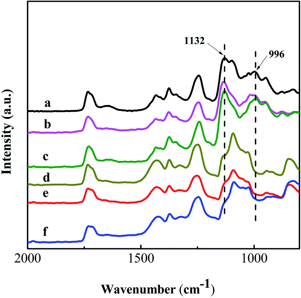 | ||
| Fig. 6 ATR-FTIR spectra of the PVA (a), PVA/GO (b) and PVA/GO/MWCNT (c) nanofiber mats after crosslinking with GA in methylbenzene (reaction condition: pH = 2–3) at room temperature for 4 h. Spectra of the uncrosslinked PVA (d), PVA/GO (e) and PVA/GO/MWCNT (f) nanofiber mats are also shown. | ||
Reduction of GO in the nanofiber mats
Fig. 7 shows the Raman spectra of GO and the PVA/GO nanofiber mat before and after reduction with hydrazine hydrate at 95 °C for 1 h. Two obvious peaks at 1348 and 1583 cm−1 exist in the spectra, which are attributed to the D band and G band of carbon, respectively. The D band corresponds to the breathing mode of k-point photons of A1g symmetry and the G band corresponds to the first-order scattering of the E2g mode, derived from the sp3 and sp2 carbon domains, respectively.45 The change in the ID/IG value (intensity ratio of the D and G bands) can prove the degree of reduction.46 After reduction by hydrazine hydrate, the ID/IG value of GO increased from 0.83 to 1.07 and the ID/IG value of the PVA/GO nanofiber mat increased from 0.83 to 1.11. These data indicate that the reduction of GO to RGO does take place.47 The increase in the ID/IG value after the reduction of GO is due to the formation of new graphitic domains, which have a smaller average size of the sp2 domains than the original one in GO, but are more numerous.48 To further prove the reduction of GO, the UV-vis absorption spectra of the GO and RGO solutions and a suspended solution of the PVA/RGO nanofiber mats were measured. Firstly, the PVA/RGO nanofiber mat was crushed in a mortar. Secondly, the crushed nanofiber mat was dispersed in deionised water with ultrasonic treatment to obtain a suspended solution of the PVA/RGO nanofiber mat. Fig. 8 shows the UV-vis spectra of the PVA/RGO nanofiber mat suspension solution and GO solution before and after reduction with hydrazine hydrate at 95 °C for 1 h. The absorption peak of GO at 230 nm undergoes a red shift to 265 nm, which indicates that GO might be reduced.49 The obvious peak at 205 nm for the PVA/RGO nanofiber mat suspension solution might be due to π–π attractions between RGO and RGO fragments.21 These fragments may have originated from the crushing process and ultrasonic treatment. | ||
| Fig. 7 Raman spectra of GO before (a) and after (c) reduction with hydrazine hydrate at 95 °C for 1 h and the PVA/GO nanofiber mat before (c) and after (d) reduction with hydrazine hydrate at 95 °C for 1 h. | ||
 | ||
| Fig. 8 UV-vis absorption spectra of the GO solution (a), the PVA/RGO solution after crushing and ultrasonic treatment of the PVA/RGO nanofiber mat in deionised water (b) and the RGO solution (c). | ||
Fig. 9 shows the FESEM images of the PVA/RGO and PVA/RGO/MWCNT nanofiber mats. It can be observed that these nanofibers maintain their original morphology after crosslinking with GA and reduction with hydrazine hydrate aqueous solution at 95 °C for 1 h. The results also show the stability of the crosslinked PVA based nanofiber mats in aqueous solution at 95 °C, which further proves the formation of crosslinked PVA based nanofiber mats.
 | ||
| Fig. 9 FESEM images of the PVA/RGO (A) and PVA/RGO/MWCNT (B) nanofiber mats prepared via the reduction of PVA/RGO and PVA/RGO/MWCNT nanofiber mats with hydrazine hydrate at 95 °C for 1 h, respectively. | ||
Fig. 10 shows digital images of the different nanofiber mats. The PVA (Fig. 10A1), PVA/GO (Fig. 10B1) and PVA/GO/MWCNT (Fig. 10C1) nanofiber mats exhibit obviously different colours. The colour of the nanofiber mat changed from white (Fig. 10A1) to brown (Fig. 10B1) with the addition of GO. However, the PVA/GO/MWCNT nanofiber mat (Fig. 10C1) was black. The uniform colours of the PVA/GO and PVA/GO/MWCNT nanofiber mats confirm that GO and GO/MWCNTs were uniformly dispersed in the PVA based nanofibers, which agrees with the results of Fig. 1–3. There were no obvious changes in colour before and after crosslinking of the PVA, PVA/GO, PVA/GO/MWCNT nanofiber mats, which confirmed that the GO and MWCNTs in the nanofibers did not change before and after crosslinking, except for the formation of the crosslinked network. Conversely, after treatment with hydrazine hydrate, the colour of the PVA/GO nanofiber mat changed from brown (Fig. 10B2) to black (Fig. 10B3) due to the blackness of the RGO derived from the reduction of GO. The PVA/GO/MWCNT nanofiber mat (Fig. 10C3) showed the most black colour, which was attributed to the high carbon content (RGO and MWCNTs) in the nanofibers.
 | ||
| Fig. 10 Digital images of the PVA (A1), PVA/GO (B1) and PVA/GO/MWCNT (C1) nanofiber mats; the PVA (A2), PVA/GO (B2) and PVA/GO/MWCNT (C2) nanofiber mats crosslinked with GA in methylbenzene (pH = 2–3, adjusted by HCl) at room temperature for 4 h and the PVA (A3), PVA/GO (B3), PVA/GO/MWCNT (C3) nanofiber mats reduced with hydrazine hydrate at 95 °C for 1 h. | ||
Properties of the nanofiber mats
Fig. 11 shows the stress–strain curves of the different nanofiber mats. Before and after crosslinking, the Young’s modulus of all the nanofiber mats increased gradually with the addition of nanofiller (GO, GO/MWCNTs) and the crosslinked nanofiber mats exhibited higher Young’s moduli. Before crosslinking, the PVA nanofiber mat exhibited the largest elongation-at-break because of the good movement of the PVA chains. After the addition of GO, hydrogen bonding between GO and PVA restricts the movement of the PVA chains.50 Therefore, the PVA/GO nanofiber mat exhibited a lower elongation-at-break. The elongation-at-break of the PVA/GO/MWCNT nanofiber mat was higher than that of the PVA/GO nanofiber mat, which was attributed to the good dispersion of the MWCNTs.51,52 After crosslinking, the chemical bonds formed between the PVA chains restrict greatly the movement of the PVA chains. Moreover, the hydrogen bonds in all of the PVA based nanofiber mats disappear when the hydroxyl groups are crosslinked by GA so the elongation-at-break values after crosslinking are almost the same. | ||
| Fig. 11 Stress–strain curves of the PVA, PVA/GO, PVA/GO/MWCNT, crosslinked PVA (c-PVA), crosslinked PVA/GO (c-PVA/GO) and crosslinked PVA/GO/MWCNT (c-PVA/GO/MWCNT) nanofiber mats. | ||
Fig. 12 shows the tensile strength of the different nanofiber mats before and after crosslinking by GA. For the uncrosslinked nanofiber mats, the tensile strength of the PVA nanofiber mat was 16.7 ± 0.7 MPa. After the addition of GO, the tensile strength of the PVA nanofiber mat decreased from 16.7 ± 0.7 to 13.2 ± 0.8 MPa. Although GO sheets can favour load transfer from the polymer matrix to GO,2 the crystallinity of the PVA matrix in the PVA/GO nanofiber mat was lower than that of the PVA nanofiber mat, as shown in Fig. 5. This is because the “hydrogen bond barrier” prevents the formation of hydrogen bonds between the PVA chains, which could reduce the crystallinity of the PVA matrix. The results agree with the results of the XRD patterns. However, some papers have reported that the tensile strength of PVA/GO nanofibers is higher than that of PVA nanofibers only when the content of GO is lower than a critical value (0.4–1 wt%).2,53 When the content of GO is higher than the critical value, the tensile strength of PVA/GO nanofibers decreases gradually. The variation is because the effect of the “hydrogen bond barrier” on crystallization is very weak in PVA/GO nanofibers with a low content of GO, as reported in the references.2,53 Also, GO sheets can favour load transfer from the polymer matrix to the GO sheets. When the content of GO is higher than the critical value, the influence of the “hydrogen bond barrier” begins to become remarkable and decreases the formation of hydrogen bonds between the PVA chains, which can reduce the crystallinity of the PVA matrix. Therefore, the tensile strength of the PVA/GO nanofibers is higher than that of the PVA nanofibers in this case. In this article, 7 wt% GO was used as the filler in the PVA based nanofibers. The content of GO was much higher than the critical value, so the tensile strength of the PVA/GO nanofibers was lower than that of the PVA nanofibers in this article. Before crosslinking, the PVA/GO/MWCNT nanofiber mat exhibited the maximum tensile strength (18.1 ± 0.5 MPa). The reason for this is that the existing MWCNTs promoted the crystallization of the PVA matrix, as shown in Fig. 5d. At the same time, the good dispersion of the MWCNTs promoted load transfer during the mechanical test. For the crosslinked nanofiber mats, GO did not influence the crystallization of PVA via the “hydrogen bond barrier” because almost all of the –OH groups in the PVA matrix had disappeared after reaction with the –CHO groups of GA during the crosslinking reaction.54 This result agrees with the results of the XRD patterns (Fig. 5). The crosslinked PVA/GO nanofiber mat had a higher tensile strength than the crosslinked PVA nanofiber mat because of load transfer from the PVA matrix to the GO sheets. It is noteworthy that the uncrosslinked nanofiber mats had lower tensile strengths than the crosslinked ones, so the nanofiber mats crosslinked with GA exhibited higher mechanical strengths. In comparison to the uncrosslinked PVA nanofiber mat (in Table S1†), the tensile strength of the crosslinked PVA nanofiber mat improved by 30%. The improvement in the tensile strength was due to the formation of the crosslinked network. The tensile strengths of the PVA/GO and PVA/GO/MWNT nanofibers before and after crosslinking showed a large variation because the influence of the “hydrogen bond barrier” disappeared after the hydroxyl groups became crosslinked. However, the degree to which the tensile strengths were enhanced was not obviously different for the PVA/GO and PVA/GO/MWCNT nanofiber mats before and after crosslinking. The small difference may be due to the different amounts of filler.
 | ||
| Fig. 12 Tensile strengths of the uncrosslinked PVA, PVA/GO and PVA/GO/MWCNT nanofiber mats and the PVA, PVA/GO and PVA/GO/MWCNT nanofiber mats crosslinked with GA (i.e. c-PVA, c-PVA/GO and PVA/GO/MWCNTs). | ||
Table 1 shows the volume conductivities of the different nanofiber mats. The pure PVA nanofiber mat had the lowest volume conductivity (5.11 ± 0.96 × 10⁻¹¹ S m−1). After the addition of GO, the volume conductivity of the PVA/GO nanofiber mat increased to 1.27 ± 0.71 × 10⁻¹⁰ S m−1 due to the conductivity of GO, which improved the volume conductivity of the PVA/GO nanofiber mat. It is noteworthy that the PVA/RGO nanofiber mat exhibited a slightly higher volume conductivity than the PVA/GO/MWCNT nanofiber mat, although the PVA/GO/MWCNT nanofiber mat had a higher carbon content than the PVA/RGO nanofiber mat. This is because GO has a lower conductivity than MWCNTs and the GO existed around the MWCNTs in the nanofibers, as shown in Fig. 3, which limited the conductivity of the MWCNTs greatly. After the PVA/GO nanofiber mat was reduced by hydrazine hydrate, the GO changed into RGO. RGO has a higher conductivity than GO.55,56 Therefore, the PVA/RGO/MWCNT nanofiber mat had the highest volume conductivity (2.33 ± 0.20 × 10⁻⁷ S m−1) because it had the highest carbon content (21 wt%) after the reduction of GO.
| Nanofiber mat | GO/PVA (% w/w) | MWCNTs/PVA (% w/w) | RGO/PVA (% w/w) | Volume conductivity (S m−1) |
|---|---|---|---|---|
| PVA | — | — | — | 5.11 ± 0.96 × 10⁻¹¹ |
| PVA/GO | 7 | — | — | 1.27 ± 0.71 × 10⁻¹⁰ |
| PVA/GO/MWCNTs | 7 | 14 | — | 1.49 ± 0.63 × 10⁻⁸ |
| PVA/RGO | — | — | 7 | 3.92 ± 0.17 × 10⁻⁸ |
| PVA/RGO/MWCNTs | — | 14 | 7 | 2.33 ± 0.20 × 10⁻⁷ |
Conclusions
A PVA/GO/MWCNT nanofiber mat was fabricated successfully with GO-assisted dispersion of the MWCNTs through the use of electrospinning technology. MWCNTs were dispersed well in the PVA matrix with the assistance of GO. In order to increase the volume conductivity of the PVA/GO/MWCNT nanofiber mat, the GO in the nanofibers was reduced using hydrazine hydrate. The obtained PVA/RGO/MWCNT nanofiber mat, containing the highest content of carbon (21 wt%), had the highest volume conductivity (2.33 ± 0.20 × 10⁻⁷ S m−1). Crosslinking not only maintained the nanofiber morphology during the process of reduction, but also increased the tensile strength of the nanofiber mats. At the same time, the crosslinked nanofibers could be stable in aqueous solution. The method reported here for improving the carbon content in nanofibers solves the problem of agglomeration of MWCNTs in nanofibers and improves the carbon content of nanofibers. Our work provides a novel method for obtaining a stable aqueous MWCNT based solution with good dispersion and for preparing highly conductive MWCNT based nanofibers with high carbon content.Acknowledgements
This work was funded by the Nature Science Foundation of China (No. 50802042), the Nature Science Foundation of Jiangsu province (No. BK2011076) and the Priority Academic Program Development of Jiangsu Higher Education Institutions (PAPD).References
- L. Jin, Z. Q. Feng, T. Wang, Z. Z. Ren, S. S. Ma, J. H. Wu and D. P. Sun, J. Mater. Chem. B, 2014, 2, 129–136 RSC.
- Y. Y. Qi, Z. X. Tai, D. F. Sun, J. T. Chen, H. B. Ma, X. B. Yan, B. Liu and Q. J. Xue, J. Appl. Polym. Sci., 2013, 127, 1885–1894 CrossRef CAS PubMed.
- X. H. Li, W. M. Yang, H. Y. Li, Y. Wang, M. M. Bubakir, Y. M. Ding and Y. C. Zhang, J. Appl. Polym. Sci., 2015, 132, 41601 Search PubMed.
- A. M. Al-Enizi, A. A. Elzatahry, A. R. I. Soliman and S. S. Al-Theyab, Int. J. Electrochem. Sci., 2012, 7, 12646–12655 CAS.
- Y. Fu, L. Liu, L. Q. Zhang and W. C. Wang, ACS Appl. Mater. Interfaces, 2014, 6, 5105–5112 CAS.
- M. Yang, T. Xie, L. Peng, Y. Zhao and D. Wang, Appl. Phys. A: Mater. Sci. Process., 2007, 89, 427–430 CrossRef CAS.
- I. D. Norris, M. M. Shaker, F. K. Ko and A. G. MacDiarmid, Synth. Met., 2000, 114, 109–114 CrossRef CAS.
- E. T. Thostenson, Z. F. Ren and T. W. Chou, Compos. Sci. Technol., 2001, 61, 1899–1912 CrossRef CAS.
- H. Liu, K. C. Zuo and C. D. Vecitis, Environ. Sci. Technol., 2014, 48, 13871–13879 CrossRef CAS PubMed.
- H. Ko, S. Park, S. Park and C. Lee, J. Nanosci. Nanotechnol., 2015, 15, 5295–5300 CrossRef CAS PubMed.
- H. Huang, C. H. Liu, Y. Wu and S. S. Fan, Adv. Mater., 2005, 17, 1652–1656 CrossRef CAS PubMed.
- M. Foldvari and M. Bagonluri, Nanomedicine, 2008, 4, 183–200 CrossRef CAS PubMed.
- G. Salimbeygi, K. Nasouri and A. M. Shoushtari, Fibers Polym., 2014, 15, 583–588 CrossRef CAS.
- J. S. Jeong, J. S. Moon, S. Y. Jeon, J. H. Park, P. S. Alegaonkar and J. B. Yoo, Thin Solid Films, 2007, 515, 5136–5141 CrossRef CAS PubMed.
- Z. Q. Ding, Y. P. Zhu, C. Branford-White, K. Sun, S. Um-I-Zahra, J. Quan, H. L. Nie and L. M. Zhu, Mater. Lett., 2014, 128, 310–313 CrossRef CAS PubMed.
- W. B. Lu, B. Liu, J. Wu, J. Xiao, K. C. Hwang, S. Y. Fu and Y. Huang, Appl. Phys. Lett., 2009, 94, 101917 CrossRef PubMed.
- P. Abadi, M. R. Maschmann, S. M. Mortuza, S. Banerjee, J. W. Baur, S. Graham and B. A. Cola, Carbon, 2014, 69, 178–187 CrossRef PubMed.
- B. Kim and W. M. Sigmund, Langmuir, 2004, 20, 8239–8242 CrossRef CAS PubMed.
- Y. B. Wang, Z. Iqbal and S. Mitra, J. Am. Chem. Soc., 2006, 128, 95–99 CrossRef CAS PubMed.
- M. J. Kim, J. Lee, D. Jung and S. E. Shim, Synth. Met., 2010, 160, 1410–1414 CrossRef CAS PubMed.
- J. Kim, L. J. Cote, F. Kim, W. Yuan, K. R. Shull and J. X. Huang, J. Am. Chem. Soc., 2010, 132, 8180–8186 CrossRef CAS PubMed.
- V. C. Tung, J. H. Huang, I. Tevis, F. Kim, J. Kim, C. W. Chu, S. I. Stupp and J. X. Huang, J. Am. Chem. Soc., 2011, 133, 4940–4947 CrossRef CAS PubMed.
- S. H. Aboutalebi, A. T. Chidembo, M. Salari, K. Konstantinov, D. Wexler, H. K. Liu and S. X. Dou, Energy Environ. Sci., 2011, 4, 1855–1865 CAS.
- J. Ma, L. Zhou, C. Li, J. H. Yang, T. Meng, H. M. Zhou, M. X. Yang, F. Yu and J. H. Chen, J. Power Sources, 2014, 247, 999–1004 CrossRef CAS PubMed.
- L. Qiu, X. W. Yang, X. L. Gou, W. R. Yang, Z. F. Ma, G. G. Wallace and D. Li, Chem.–Eur. J., 2010, 16, 10653–10658 CrossRef CAS PubMed.
- D. Chen, H. B. Feng and J. H. Li, Chem. Rev., 2012, 112, 6027–6053 CrossRef CAS PubMed.
- S. K. Pillai, S. S. Ray and M. Moodley, J. Nanosci. Nanotechnol., 2008, 8, 6187–6207 CrossRef CAS PubMed.
- O. Koysuren, J. Polym. Eng., 2012, 32, 407–413 CAS.
- W. P. Zhou, Y. L. Wu, F. Wei, G. H. Luo and W. Z. Qian, Polymer, 2005, 46, 12689–12695 CrossRef CAS PubMed.
- V. Mani, S. M. Chen and B. S. Lou, Int. J. Electrochem. Sci., 2013, 8, 11641–11660 CAS.
- C. Zhang, S. Huang, W. W. Tjiu, W. Fan and T. X. Liu, J. Mater. Chem., 2012, 22, 2427–2434 RSC.
- Y. Tan, Y. Song and Q. Zheng, Nanoscale, 2012, 4, 6997–7005 RSC.
- H. Fong, I. Chun and D. H. Reneker, Polymer, 1999, 40, 4585–4592 CrossRef CAS.
- H. Bang, M. Gopiraman, B. S. Kim, S. H. Kim and I. S. Kim, Colloids Surf., A, 2012, 409, 112–117 CrossRef CAS PubMed.
- M. Srivastava, M. E. Uddin, J. Singh, N. H. Kim and J. H. Lee, J. Alloys Compd., 2014, 590, 266–276 CrossRef CAS PubMed.
- M. Naebe, T. Lin, W. Tian, L. M. Dai and X. G. Wang, Nanotechnology, 2007, 18, 225605 CrossRef.
- L. M. Guerrini, M. P. de Oliveira, M. C. Branciforti, T. A. Custodio and R. E. S. Bretas, J. Appl. Polym. Sci., 2009, 112, 1680–1687 CrossRef CAS PubMed.
- Y. S. Zhou, H. J. Yang, X. Liu, J. Mao, S. J. Gu and W. L. Xu, Int. J. Biol. Macromol., 2013, 53, 88–92 CrossRef CAS PubMed.
- C. Bao, Y. Guo, L. Song and Y. Hu, J. Mater. Chem., 2011, 21, 13942–13950 RSC.
- J. J. Li, L. S. Shao, X. H. Zhou and Y. H. Wang, RSC Adv., 2014, 4, 43612–43618 RSC.
- T. Ohta, T. Ito, M. Shimizu, L. Tauchi, H. D. Nguyen-Tran, J. C. Park, B. S. Kim, I. S. Kim and K. Ohta, Polym. Adv. Technol., 2011, 22, 2653–2658 CrossRef CAS PubMed.
- A. G. Destaye, C. K. Lin and C. K. Lee, ACS Appl. Mater. Interfaces, 2013, 5, 4745–4752 CAS.
- R. P. Shaikh, P. Kumar, Y. E. Choonara, L. C. du Toit and V. Pillay, Biofabrication, 2012, 4, 025002 CrossRef PubMed.
- R. Guo, C. Hu, B. Li and Z. Jiang, J. Membr. Sci., 2007, 289, 191–198 CrossRef CAS PubMed.
- X. F. Li, J. F. Shen, N. Li and M. X. Ye, J. Power Sources, 2015, 282, 194–201 CrossRef CAS PubMed.
- J. L. Zhang, H. J. Yang, G. X. Shen, P. Cheng, J. Y. Zhang and S. W. Guo, Chem. Commun., 2010, 46, 1112–1114 RSC.
- X. D. Qi, X. L. Yao, S. Deng, T. N. Zhou and Q. Fu, J. Mater. Chem. A, 2014, 2, 2240–2249 CAS.
- S. Stankovich, D. A. Dikin, R. D. Piner, K. A. Kohlhaas, A. Kleinhammes, Y. Jia, Y. Wu, S. T. Nguyen and R. S. Ruoff, Carbon, 2007, 45, 1558–1565 CrossRef CAS PubMed.
- D. Li, M. B. Muller, S. Gilje, R. B. Kaner and G. G. Wallace, Nat. Nanotechnol., 2008, 3, 101–105 CrossRef CAS PubMed.
- C. Wang, Y. Li, G. Ding, X. Xie and M. Jiang, J. Appl. Polym. Sci., 2013, 127, 3026–3032 CrossRef CAS PubMed.
- D. Chen, R. Y. Wang, W. W. Tjiu and T. X. Liu, Compos. Sci. Technol., 2011, 71, 1556–1562 CrossRef CAS PubMed.
- L. D. Tijing, W. Choi, Z. Jiang, A. Amarjargal, C. H. Park, H. R. Pant, I. T. Im and C. S. Kim, Curr. Appl. Phys., 2013, 13, 1247–1255 CrossRef PubMed.
- Y. Liu, M. Park, H. K. Shin, B. Pant, J. Choi, Y. W. Park, J. Y. Lee, S.-J. Park and H.-Y. Kim, J. Ind. Eng. Chem., 2014, 20, 4415–4420 CrossRef CAS PubMed.
- H. S. Mansur, R. L. Orefice and A. A. P. Mansur, Polymer, 2004, 45, 7193–7202 CrossRef CAS PubMed.
- R. H. Wang, Y. Wang, C. H. Xu, J. Sun and L. Gao, RSC Adv., 2013, 3, 1194–1200 RSC.
- Y. Wang, L. Chen, J. R. Yu, J. Zhu, Z. X. Shi and Z. M. Hu, RSC Adv., 2013, 3, 12255–12266 RSC.
Footnote |
| † Electronic supplementary information (ESI) available. See DOI: 10.1039/c5ra15985g |
| This journal is © The Royal Society of Chemistry 2015 |