 Open Access Article
Creative Commons Attribution 3.0 Unported Licence
The synthesis and application of novel benzodithiophene based reactive mesogens with negative wavelength dispersion birefringence†‡
James D. W.
Allen
*ab,
Kevin
Adlem
a and
Martin
Heeney
 *b
*b
aMerck Performance Materials Ltd., 1 Venture Road, Southampton, SO16 7NP, UK. E-mail: james.allen@merckgroup.com
bDepartment of Chemistry and Centre for Processable Electronics, Imperial College London, London W12 0BZ, UK. E-mail: m.heeney@imperial.ac.uk
First published on 18th November 2021
Abstract
Optical corrective retardation films are widely used in the display industry to compensate for a variety of imperfections such as off-axis contrast reduction, grey-scale inversion and colour shifts in LCDs and backplane reflections in OLEDs. A wide variety of these films have been produced by multiple methods, however, obtaining ideal wavelength dispersion remains difficult and costly to achieve in thin, single-layer systems. In this work, we report the synthesis of a novel series of reactive mesogen materials designed to exhibit negative wavelength dispersion birefringence. This series of photopolymerisable materials based on a benzodithiophene core exhibiting either an ‘X’-shaped or ‘T’-shaped geometry were synthesised. Their negative wavelength dispersion birefringence properties were investigated in aligned films prepared from photo-polymerised reactive mesogen host mixtures. The nature of the substituents on the BDT core was found to have a significant impact on performance, and materials with an X-shaped geometry were found to exhibit much higher performance than those with a T-shape.
Introduction
The term Liquid Crystal refers to a distinct and unique phase of matter in-between that of a liquid and a solid, which is free-moving but possesses a long-range orientational order along a director.1 Reactive mesogens (RMs) are a type of liquid crystal material with the characteristic property of possessing polymerizable groups.2–5 The presence of these groups allows for the polymerisation of the material in its liquid crystal phase to produce a solid anisotropic polymer. The resultant polymer retains the alignment and optical properties of its parent liquid crystal texture while being stable to mechanical stress and thermal variations up to the thermal degradation of the material.6–8RMs have found a variety of applications, most notably in the display industry. Due to their compatibility with liquid crystalline mixtures, RMs have found use as additives in fast switching polymer stabilised liquid crystal display modes, such as the polymer stabilised vertically aligned mode (PS-VA).9–11 In this application, a small amount of RM, typically less than 1%, is doped into a liquid crystal mixture, filled into the application cell and switched to the on-state. The RM is then cured to afford a polymer network that exerts a restoring force on the liquid crystal, giving rise to faster switching with lower voltage requirements.10 In addition due to their anisotropic optical properties, polymerised thin films of RMs are also used as optical corrective films for both LC12 and OLED13 displays. Films produced in this way offer several advantages in comparison to conventional stretched polymer films,14 such as micro-patterning by inkjet printing, in-cell film coating processes and reduction in film thickness, in addition to the increased variety of optical films possible.15
One of the challenges posed in the area of liquid crystal devices and films is that of optical dispersion.16 In such systems the relative retardation of the ordinary and extraordinary rays passing through an active layer is carefully tuned to give the desired optical effect. However, due to dispersion in the birefringence, this can only be optimised for a single wavelength. In a system with normal dispersion, wavelengths shorter and longer than the optimised wavelength experience too much or too little retardation, respectively. This effect is shown in Fig. 1, which shows the retardation profile of an ideal broadband quarter waveplate and that of one made with a material with normal dispersion, optimised for 550 nm light. In general, the ideal dispersion properties required can be very specific to the optical application, a poorly optimised system can lead to light leakage in a display, affecting contrast and causing colour abnormalities.12
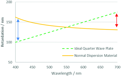 | ||
| Fig. 1 Retardation profiles for an ideal quarter-wave plate and material with normal dispersion optimised for a wavelength of 550 nm. Arrows denote the discrepancy observed at different wavelengths. | ||
It is possible to counteract the effects of dispersion through the inclusion of materials that exhibit a different ratio of dispersion to birefringence, either as an additional layer in an optical stack or, if compatible, incorporated into an existing layer.17,18 If the compensation is provided by an additional layer in the optical stack, this different ratio is sufficient. However, in a RM system, the additional possibility exists of incorporating the compensating material with other RM components in a single layer to achieve zero dispersion overall. In this case, all the components share a common alignment and optical axis and the compensating material must then exhibit negative dispersion – that is, the birefringence is larger, at longer wavelengths. Such materials will commonly also exhibit a negative optical birefringence, meaning the refractive index is smaller for short wavelengths and larger for long wavelengths.19 It is possible to create this effect by manipulating the birefringence in liquid crystal systems to cause negative wavelength dispersion of birefringence, commonly referred to as simply ‘negative dispersion’. A material exhibiting negative dispersion requires a larger no which increases at a higher rate at lower wavelengths compared to the ne to give a negative birefringence profile which increases with wavelength, as shown in Fig. 2.20
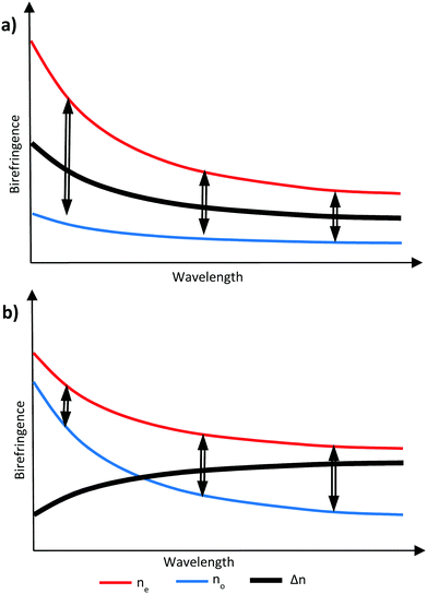 | ||
| Fig. 2 Graphical representation of (a) no is smaller and less wavelength dependant giving positive dispersion and (b) when no is larger and more wavelength dependant giving negative dispersion. | ||
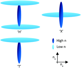
Through the use of reactive mesogens and careful molecular design, it is possible to create a thin single-layer film with zero or negative dispersion properties. To achieve this, materials must be created which have a large no and minimize ne without compromising alignment direction. This is typically achieved by designing compounds incorporating one or more large structural units with a liquid crystal-like shape but low polarizability, and therefore a small contribution to the optical properties of the additive. The long axes of these units determine the alignment direction of the final compound in a liquid crystalline phase. The optical properties of the compound are dominated by a further unit that has high polarizability anisotropy, with its principal polarizability axis fixed orthogonal to the alignment direction. This results in materials that can be described as ‘H’, ‘X’ and ‘T’ shaped (Fig. 3).21
Several examples of materials fitting this design profile have been reported, with benzothiazole systems a popular choice for the optically important high polarizability unit.22–24 Other fused 5–6 membered rings have been used to create ‘H’ shapes,25 and ‘T’ shaped materials.26 Alternative molecular geometries have also been utilised such as the sp3 geometry in a 9H-fluorene ring system to create an ‘X’ shaped materials27–29 and axial substitution on cyclohexane rings.30–32 Nevertheless, most of these systems have only been reported in the patent literature, and a systematic study of the structure–property relationship of negative dispersion materials has yet to be reported to the best of our knowledge. Here we report the synthesis and negative dispersive properties of a new series of RMs. These materials utilise benzodithiophene (BDT) cores, in which substituents are attached at the orthogonal 2,6 and 4,8-positions and 2 and 4,6 positions to create ‘X’ and ‘T’ shaped molecular geometries respectively.
Results and discussion
Material design and synthesis
To prepare the RM materials, we required a BDT intermediate in which the reactivity of the 2,6 and 4,8 positions was readily differentiated. We reasoned that hydroxy groups in the 4,8 position would be a convenient approach to attach liquid crystalline ‘aligning’ groups, via ester formation. Halogenation of the thienyl groups of the BDT, which was expected to occur selectively in the more reactive alpha (2,6-) positions, should provide intermediates that could be further functionalised via standard cross-coupling approaches. Therefore, the common intermediates, 2,6-diiodo-4,8-dimethoxy-benzodithiophene (5a) and 2-iodo-4,8-dimethoxy-benzodithiophene (5b) were prepared according to Scheme 1. Wherein, 3-thiophenecarboxylic acid was readily converted to benzo[1,2-b:4,5-b′]dithiophen-4,8-dione (3) following procedures previously reported.33,34 Reduction to benzodithiophenediol occurred readily, but efforts to use this material directly in subsequent steps were complicated by its poor solubility and competing side reactions. Thus, the hydroxy groups were protected as methyl ethers, allowing the ready synthesis of 4,8-dimethoxybenzodithiophene (4) at the 100 g scale. Dilithiation of 4 with n-BuLi/TMEDA, followed by reaction with molecular iodine afforded the diiodide (5a) in good yield when performed at the gram scale. Upon upscaling to a larger (100 gram) scale, we obtained a significant amount of the mono-iodinated by-product 5b, which was useful for the generation of ‘T’ shaped materials. The incomplete iodination likely resulted from difficulties in temperature control and mixing at larger scales.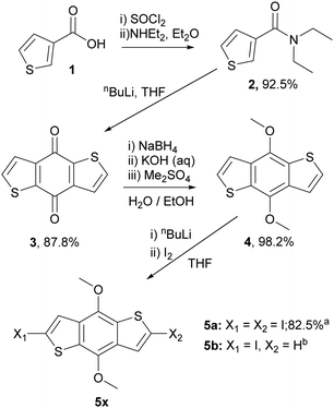 | ||
| Scheme 1 The synthetic route and yields to common benzodithiophene intermediates 5a and 5b. aYield for reaction on 1 g scale, bIsolated as a side product from the reaction on 100 g scale. | ||
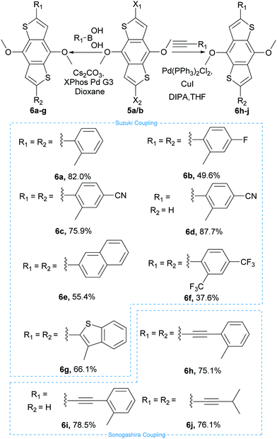
These intermediates were then subsequently functionalised using Suzuki and Sonogashira couplings to give a variety of methoxy protected core materials (Scheme 2). The methoxy protected cores (6a–j) were then deprotected, to form the corresponding benzodithiophenediols (8a–j). For the purely heteroaromatic cores (6a–g), the use of BBr3 for the demethylation proceeded smoothly, and the air-sensitive diols were readily isolated by precipitation and filtration. However, attempts to deprotect the alkyne containing 6h–j under equivalent conditions gave complex mixtures from which no product could be isolated. Therefore, we developed an alternative protocol in which the methoxy adducts 6h–j were oxidized, using aqueous ceric ammonium nitrate in acetonitrile, to the corresponding benzodithiophendiones (7h–j), which could be readily isolated and purified by recrystallisation. Subsequent reduction using sodium borohydride in ethanol/water afforded the benzodithiophenediol cleanly (Scheme 3). The benzodithiophenediols (8a–j) were observed to be unstable in air and decomposed to an insoluble product, suspected to be the corresponding dione. For this reason, these products were not purified before further reaction.
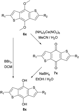 | ||
| Scheme 3 Deprotection of methoxy protected BDTs, left route used for Suzuki coupled products and right-hand route for Sonogashira products. ‘x’ defined relative to starting material 6a–j. | ||
For the preparation of the mesogenic arms, we developed a convenient protocol based on the conversion of a commercially available trans-cyclohexane derivative (Scheme 4). Following the work of Buchwald and co-workers,35 the conversion of the aryl chloride to a phenol group via Pd catalysed hydroxylation worked well. Subsequent alkylation, saponification and alkylation with an acrylate precursor (3-chloropropanoyl chloride) afforded 13, which was converted into the reactive acid chloride (14). The reaction of 14 with diols 8a–j in the presence of triethylamine resulted in the double esterification of the dihydroxy groups with the simultaneous conversion of the 3-chloropropionate to reactive acrylate groups in one pot to give the final products 15a–j (Scheme 5). The final products while typically giving good conversion and crude yields, tended to have relatively poor solubility and purification by column chromatography, therefore, resulted in reduced overall yields. Nevertheless, all compounds exhibited good purity, as measured by HPLC and their structures were confirmed by NMR spectroscopy (see ESI‡).
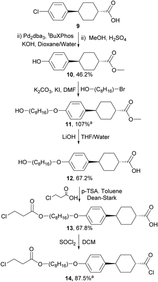 | ||
| Scheme 4 The synthesis of aligning mesogenic arm unit, aproduct used without purification - crude yield given. | ||
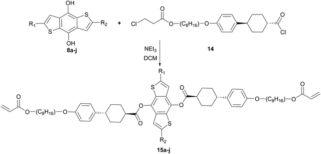 | ||
| Scheme 5 Reaction scheme to give final product (15a–j) where R1 and R2 are defined relative to the starting material described in Scheme 2. | ||
An important aspect for potential application as optical corrective films is the absorption of the material should have minimal overlap with the visible spectrum to avoid colouring of the resultant film. The optical absorption spectra of 15a–j are shown in Fig. S21–S30 (ESI‡) and summarised in Table 1. In general, the spectra are complex, with multiple clearly distinguishable absorption peaks. All materials exhibited similar absorption in the high energy region between 200–300 nm, with two main peaks centred around 230 and 270 nm. In some materials, clear shoulders or split peaks were apparent. The materials differed more significantly in the region above 300 nm, with some materials exhibiting an undesirable absorption tail into the visible region. This was particularly evident in 15e and 15g due to extended conjugation from the appended 10π-aromatics. Compound 15h in which an alkyne group was inserted between the BDT core and the ortho-tolyl substituent exhibited a similar issue. In this case, the positioning of the alkyne spacer between the BDT and tolyl substituent may reduce the torsional twisting, facilitating molecular planarization and therefore an extended conjugated system that absorbs into the visible.
| Compound | λ max/nm |
|---|---|
| Where ‘sh’ denotes a peak shoulder. Molar absorption coefficient and full spectra are available in the ESI. | |
| 15a | 232.5, 274.5, 347sh, 323 |
| 15b | 232.5, 273.5, 319, 349 |
| 15c | 235, 280, 334.5, 376sh |
| 15d | 232.5, 274, 325, 344 |
| 15e | 230.5, 277, 362, 384sh, 401.5 |
| 15f | 233, 271, 323, 357.5 |
| 15g | 231.5, 275.5, 370.5, 395sh |
| 15h | 230.5, 242sh, 281.5, 360.5, 379sh, 402.5 |
| 15i | 233, 274.5, 286.5, 327sh, 343, 358, 375.5 |
| 15j | 232.5, 270.5sh, 280.5, 320, 335.5, 357, 375.5 |
Negative dispersion properties
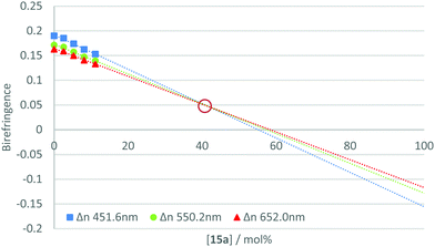
The measurement of the negative dispersion behaviour for each pure material was complicated by the requirement to form a thin film with uniform alignment. Since the individual materials did not independently exhibit the desired phase behaviour, films were formed by blending the active component with a reactive mesogen host. Therefore, to determine the relative strength of the negative dispersion for each material, they were incorporated at varying concentrations into a standard reactive mesogen mixture (Table S1, ESI‡). The phase transitions of the resulting host are given in Table S2 (ESI‡). Thin films of the mixture were spin-coated onto alignment layers (rubbed polyimide) from toluene solution, annealed in the nematic phase and photo-polymerised under a nitrogen atmosphere to afford uniaxially planar aligned polymerised films. The on-axis retardation of the films was then measured using an ellipsometer for wavelengths 400–1000 nm, with the birefringence calculated from the film thickness.The calculated birefringence for each concentration was plotted and a trend line extrapolated for three specific wavelengths (450, 550 and 650 nm). This gave the theoretical birefringence of the material at higher concentrations in the host mixture. This method allows properties to be examined at concentrations at which uniform alignment and desired phase behaviour could not be achieved. An example plot is shown in Fig. 4. For further data see Fig. S1–S20 (ESI‡).
From this data, it is possible to obtain a point at which the lines converge and intersect. At this point, the birefringence is not dependent upon wavelength and the theoretical mixture could be described to have neutral dispersion. This point can be referred to as the ‘neutral point’, and its occurrence at low concentrations of the additive indicates a strong negative dispersion in the compound under test. Estimating the neutral point in such a way allows for relative comparisons to be made between the materials in the series. Table 2 gives the extrapolated neutral points for the compounds in the 15a–j series.
Examination of Table 2 indicates that several of the series exhibit strong negative dispersion properties. Compounds 15c, 15h and 15g express the strongest effect, giving neutral points at 14.0, 16.2 and 16.6 mol%, respectively. 15e also displayed significant negative dispersion, however, the material had particularly poor solubility in the host mixture and could not be measured in concentrations greater than 7.5 wt% (3.7 mol%). The poor solubility is likely related to the absence of an ortho substituent in the naphthalene terminal group. The ortho substituents help to prevent planarization of the conjugated core due to steric interactions with the beta-hydrogens of the adjacent BDT core.36
It has long been recognised that a materials refractive index and the absorption spectra are mathematically linked through Kramers–Kronig relations.37,38 As such, we investigated if the observed negative dispersion neutral points could be directly correlated with the measured absorption spectra. Fig. 5 shows a plot of the average molar absorption coefficient (ε) over the region 300–500 nm versus the observed neutral points. This longer wavelength region, intersecting with the visible spectrum, is expected to have a larger impact on dispersion. In most of the ‘X’ shaped examples, a general trend can be observed showing that a higher absorption coefficient tends to give stronger negative dispersion. However, the compounds in this series appear mostly in two groups firstly, with 15a, b & f, all giving neutral points between 33–41% and secondly, 15e, h & g with neutral points between 16–19%. A rough correlation can be observed between absorption and neutral point for these materials, although we note that none of the compounds exhibited average absorption coefficients at intermediate values, which makes defining this trend definitively difficult. Nevertheless, it can be seen that extending the conjugation length of the core, for example comparing 15a to 15h (identical except for an additional alkyne group) clearly results in a red-shift and increase in absorption, and a reduction in neutral point. Similar observations can be made for 15e and 15g, which also red-shift and increase absorption by extending conjugation. However, the beneficial reduction in neutral point comes at the expense of an undesirable absorption tail into the visible region in these cases.
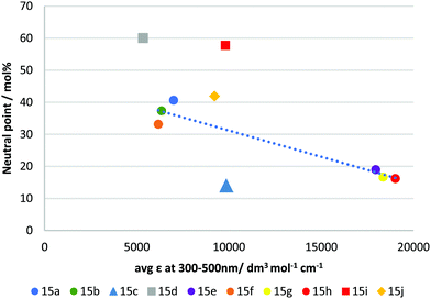 | ||
| Fig. 5 Plot showing average molar absorption coefficient (ε) from 300–500 nm vs extrapolated neutral point in RM-257 host mixture. The dotted line is a guide to the eye. | ||
Compound 15j almost falls within the first group (15a, b & f), however, despite its slightly higher average absorption coefficient, its performance is lower than those in this group, giving a neutral point of 41.9 mol%. Compound 15j differs structurally from the other examples in that it does not possess aromatic rings in the units coupled to the benzodithiophene core, using only alkyl functionalised alkyne linkages to afford polarizability. This change in molecular shape may explain its behaviour. The compounds 15d and 15i were shown to be the least effective of the materials produced, giving neutral points of 60.0 & 57.8 mol%, respectively. These compounds are the two asymmetrical mono-coupled examples from the series, where R2 = H, giving more ‘T’ shaped materials. Clearly in direct comparison to their ‘X’ shaped analogues, 15e and 15h they are much less effective. Like 15j, the reduced performance can be attributed to the decrease in molecular width and reduced polarizability. Additionally, the change in molecular shape can explain why these materials do not fit the trend observed for other materials produced. Of significant interest is compound 15c which gave the best negative dispersion performance, with a neutral point of 14.0 mol%. In this case, its behaviour is anomalous when compared to its average absorption coefficient. As shown in Fig. 5 the average absorption coefficient between 300–500 nm is much lower compared to that of materials with comparable performance, and it does not have an undesirable absorption tail towards the visible spectrum. In comparing 15c to 15a/b it is apparent that replacing the H/F substituent in the para position with the electron withdrawing nitrile group is an effective strategy to lower the neutral point. Compound 15f which contains a strongly electron withdrawing but non-conjugated trifluoromethyl group in the para position, is less-effective (although we note that the ortho group is also changed in 15f), suggesting that the combination of the extended conjugation system of the nitrile group, together with its electron-withdrawing effect is an important design criterion.
Conclusions
We have reported the synthesis and characterisation of a series of new reactive mesogens designed to exhibit negative wavelength dispersion birefringence. The series was based on a benzodithiophene (BDT) central core in which various (hetero)aryl groups were attached to either one or both thienyl units in BDT, either directly or via an alkyne spacer. For the alkynyl functionalised BDT cores, we developed a new deprotection protocol based on the oxidation of the bis(methoxy) ether of BDT, followed by reduction of the resulting quinone. Such a synthetic strategy avoided degradation of the triple bond by BBr3 and allowed photopolymerisable mesogenic arms to be appended to the central quinol ring of the BDT. The resulting molecules exhibited either ‘T’ or ‘X’ shaped molecular geometries and were aligned and polymerised in a reactive mesogen host mixture by irradiation with UV light.The birefringence of the resulting films was measured at various concentrations of additive, and the data extrapolated to afford a neutral point, at which birefringence is not dependent upon wavelength. All materials were found to express significant negative dispersion in the chosen host mixture, and a comparison of the neutral points reveals two important trends. Firstly, that the performance of asymmetric ‘T’ shaped materials was significantly reduced compared to their ‘X’ shaped analogues. Secondly, a correlation was found showing that compounds with a higher average molar absorption coefficient over the 300–500 nm range tended to give better negative dispersion performance. For several examples, this came at the expense of an undesirable absorption tail into the visible region. Pleasingly one example, incorporating 2-methyl-4-cyanobenzene substituents, did not follow this trend and gave an extrapolated neutral point of 14.0 mol%, which was significantly lower than expected compared to its absorption profile. These results demonstrate that benzodithiophene based materials have the potential to be used as active materials in optical corrective films designed to exhibit negative wavelength dispersion birefringence.
Conflicts of interest
This work was undertaken as part of research projected funded by Merck Performance Materials Ltd a subsidiary of Merck KGaA, Darmstadt, Germany. A patent application has been filed on the materials described in this work.Acknowledgements
We would like to thank Merck Performance Materials Ltd for providing the funding and facilities for this work. M. H. thanks the Royal Society, and the Wolfson Foundation (Royal Society Wolfson Fellowship) for funding. We thank all staff at Merck Chilworth for their invaluable help and support in this endeavour. Finally, we would like to thank Prof. Ian Sage of Abelian Services for his helpful discussions with regard to this publication.References
- W. H. de Jeu, in Phase Transitions in Liquid Crystals, ed. S. Martellucci and A. N. Chester, Springer, Boston, MA, 1993, vol. 290, pp. 3–16 Search PubMed.
- A. Bacher, P. G. Bentley, D. D. C. Bradley, L. K. Douglas, P. A. Glarvey, M. Grell, K. S. Whitehead and M. L. Turner, J. Mater. Chem., 1999, 9, 2985–2989 RSC.
- D. J. Broer, C. M. W. Bastiaansen, M. G. Debije and A. P. H. J. Schenning, Angew. Chem., Int. Ed., 2012, 51, 7102–7109 CrossRef CAS PubMed.
- A. McGlashon, W. Zhang, D. M. Smilgies, M. Shkunov, K. Genevicius, K. S. Whitehead, A. Amassian, G. G. Malliaras, D. D. C. Bradley, M. Heeney and A. J. Campbell, Curr. Appl. Phys., 2012, 12, e59–e66 CrossRef.
- I. McCulloch, M. Coelle, K. Genevicius, R. Hamilton, M. Heckmeier, M. Heeney, T. Kreouzis, M. Shkunov and W. Zhang, Jpn. J. Appl. Phys., 2008, 47, 488–491 CrossRef CAS.
- H. Thiem, P. Strohriegl, M. Shkunov and I. McCulloch, Macromol. Chem. Phys., 2005, 206, 2153–2159 CrossRef CAS.
- L. T. de Haan, C. Sánchez-Somolinos, C. M. W. Bastiaansen, A. P. H. J. Schenning and D. J. Broer, Angew. Chem., Int. Ed., 2012, 51, 12469–12472 CrossRef CAS PubMed.
- H. Thiem, M. Jandke, D. Hanft and P. Strohriegl, Macromol. Chem. Phys., 2006, 207, 370–381 CrossRef CAS.
- S. M. Kim, I. Y. Cho, W. I. Kim, K.-U. Jeong, S. H. Lee, G.-D. Lee, J. Son, J.-J. Lyu and K. H. Kim, Jpn. J. Appl. Phys., 2009, 48, 032405 CrossRef.
- J. J. Lyu, H. Kikuchi, D. H. Kim, J. H. Lee, K. H. Kim, H. Higuchi and S. H. Lee, J. Phys. D: Appl. Phys., 2011, 44, 325104 CrossRef.
- Y. R. Kwon, Y. E. Choi, P. Wen, B. H. Lee, J. C. Kim, M.-H. Lee, K.-U. Jeong and S. H. Lee, J. Phys. D: Appl. Phys., 2016, 49, 165501 CrossRef.
- Y. Saitoh, in Handbook of Visual Display Technology, ed. J. Chen, W. Cranton and M. Fihn, Springer International Publishing, Switzerland, 2016, ch. Optical Compensation Films and Polarizers, pp. 2277–2289 Search PubMed.
- R. Singh, K. N. Narayanan Unni, A. Solanki and Deepak, Opt. Mater., 2012, 34, 716–723 CrossRef.
- T. Sato, Introd. Polym. Sci. Technol., 2012, 39, 15–24 CrossRef.
- C.-J. Yun and J.-K. Song, J. Inf. Disp., 2017, 18, 119–129 CrossRef CAS.
- S. T. Wu, J. Appl. Phys., 1991, 69, 2080–2087 CrossRef CAS.
- S. Yang, H. Lee and J.-H. Lee, Opt. Express, 2015, 23, 2466–2471 CrossRef CAS PubMed.
- J. Hwang, S. Yang, Y.-J. Choi, Y. Lee, K.-U. Jeong and J.-H. Lee, Opt. Express, 2016, 24, 19934–19939 CrossRef CAS PubMed.
- M. Yamaguchi, M. E. A. Manaf, K. Songsurang and S. Nobukawa, Cellulose, 2012, 19, 601–613 CrossRef CAS.
- O. Parri, G. Smith, R. Harding, H.-J. Yoon, I. Gardiner, J. Sargent and K. Skjonnemand, Proc. SPIE, 2011, 7956, 79560W CrossRef.
- M. Yamamoto, K. Endo, Y. Kuwana and I. Nishiyama, J. Soc. Inf. Disp., 2017, 25, 405–410 CrossRef CAS.
- Y. Kuwana, M. Horiguchi, T. Ishii, S. Nose and A. Koiso, WO Pat., WO2016/114255, 2016 Search PubMed.
- M. Horiguchi, S. Nose and A. Koiso, WO Pat., WO2016/104317, 2016 Search PubMed.
- H. Matsuyama, S. Morishima and Y. Nakazawa, US Pat., US2015/0277007, 2015 Search PubMed.
- H. Nishikawa, R. Hamasaki and A. Ohkawa, WO Pat., WO2005/085222, 2005 Search PubMed.
- T. Norie, T. Kouji, R. Rieko, N. Yukihito, M. Kenji and K. Midori, WO Pat., WO2013/136977, 2013 Search PubMed.
- M. Yamahara and H. Hasegawa, WO Pat., WO2006052001, 2006 Search PubMed.
- T. Motoyoshi, Y. Okada, K. Oda and K. Yamanaka, US Pat., US2016/0326311, 2016 Search PubMed.
- K. Adlem, O. L. Parri, K. Skjonnemand and D. Wilkes, WO Pat., WO2009/030352, 2009 Search PubMed.
- J. H. Kim, S.-H. Chun, K. C. Seo, M. H. Lee and J. S. Ahn, WO Pat., WO2015/046827, 2015 Search PubMed.
- J. Sargent, O. L. Parri, K. Adlem and H. Arasi, US Pat., US2017/226421, 2017 Search PubMed.
- T. Ohyama, K. Park, H. Choi and K. Kamada, US Pat., US2017/212288, 2017 Search PubMed.
- T. Bilkay, K. Schulze, T. Egorov-Brening, K. Fink and S. Janietz, Org. Electron., 2013, 14, 344–353 CrossRef CAS.
- P. Beimling and G. Kobmehl, Chem. Ber./Recl., 1989, 119, 3198–3203 CrossRef.
- K. W. Anderson, T. Ikawa, R. E. Tundel and S. L. Buchwald, J. Am. Chem. Soc., 2006, 128, 10694–10695 CrossRef CAS PubMed.
- Z. Fei, P. Pattanasattayavong, Y. Han, B. C. Schroeder, F. Yan, R. J. Kline, T. D. Anthopoulos and M. Heeney, J. Am. Chem. Soc., 2014, 136, 15154–15157 CrossRef CAS PubMed.
- H. A. Kramers, Atti Cong. Intern. Fisica. Como, 1927, 2, 545–557 Search PubMed.
- T. Sai, M. Saba, E. R. Dufresne, U. Steiner and B. D. Wilts, Faraday Discuss., 2020, 223, 136–144 RSC.
Footnotes |
| † Dedicated to the memory of Professor Alasdair Campbell. |
| ‡ Electronic supplementary information (ESI) available. See DOI: 10.1039/d1tc05068k |
| This journal is © The Royal Society of Chemistry 2021 |

