
 Open Access Article
 This Open Access Article is licensed under a
 Creative Commons Attribution 3.0 Unported Licence
Elucidating the role of metal-ion co-doping towards boosting upconversion luminescence in gadolinium vanadate†
Aditya
Chauhan
*a,
Smile
Kataria
a,
Dmitry
Busko
a,
Fernando Arteaga
Cardona
a,
Andrey
Turshatov
 a and
Bryce S.
Richards
*ab
a and
Bryce S.
Richards
*ab
aInstitute of Microstructure Technology, Karlsruhe Institute of Technology, Hermann-von-Helmholtz-Platz 1, 76344, Eggenstein-Leopoldshafen, Germany. E-mail: aditya.chauhan@kit.edu
bLight Technology Institute, Karlsruhe Institute of Technology, Engesserstrasse 13, 76131 Karlsruhe, Germany. E-mail: bryce.richards@kit.edu
First published on 4th November 2021
Abstract
Metal co-doping is a popular approach for boosting two-photon upconversion (UC) luminescence in phosphors. The underlying mechanisms of this enhancement are still debated, being attributed primarily to modification of lattice parameters and enlargement of grain size among other effects. However, little effort has been made to elucidate the role and relative contribution of such phenomena. Hence, this study aims to isolate the comparative effects of these factors on UC luminescence using GdVO4:Yb3+/Er3+ phosphors as a model system. The nanoscale phosphors – co-doped with Zn2+ (5–30%) or Sc3+ (5–25%) – were prepared using a co-precipitation method. Zn2+ co-doping resulted in a photoluminescent quantum yield (PLQY) boost of ∼60 × under 980 nm excitation (15 W cm−2). This improvement was attributed largely to the simultaneous action of lattice shrinkage and particle size enlargement. Only ∼20 × enhancement was achieved via Sc3+ co-doping, attributed exclusively to reduction in the lattice. The results indicate that particle size is likely the largest contributor towards improved UC in inorganic phosphors. This trend was also confirmed through (Sc3+/Zn2+-free) larger microparticles–synthesized via a solid-oxide method – that exhibited ∼50 × improvement.
1. Introduction
Lanthanide-ion doped (Ln3+) inorganic luminescent phosphors are an important class of optical materials and find application in a variety of fields ranging from optical thermometers,1,2 light emitting diodes,3–5 lasers,6,7 anti-counterfeiting,8 and optical sensors9 to markers for plastic recycling10 or bio-imaging.11–13 Nevertheless, luminescence in most inorganic phosphors is marred by an overall-low emission intensity. This is especially true for the multi-photon non-linear process of upconversion (UC) and originates primarily from the parity-forbidden 4f–4f transitions of the lanthanide ions.14 However, this rule is slightly relaxed by the crystal field of some non-centrosymmetric materials leading to the generally observed luminescence. Hence, it is reasoned that altering the crystal field splitting at the Ln3+ site would improve the optical performance considerably.14In this regard, co-doping with alkali or transition metal ions has proven to be a very popular approach. Various ions such as Li+ (ionic radius 92 pm),15 Zn2+ (90 pm),16 Na+ (118 pm),17 and Bi3+ (117 pm)18 have been systematically investigated as both alio (oxygen imbalance) and homovalent (charge balanced) dopants. Especially, Li+ and Zn2+ co-doping has attracted considerable attention for a range of inorganic phosphors including fluorides,19–21 binary oxides,22–26 aluminates,27 titanates,28,29 and vanadates.16,30–33 It is reported that with optimized doping concentration, a large (≥10 ×) improvement in luminescence can be readily obtained. However, the exact mechanism for such ameliorated performance is still up for debate. In this regard, the following major theories are commonly cited as plausible explanations: (i) change in lattice parameters; (ii) enlargement of particle size; (iii) other effects such as concentration quenching and oxygen vacancies. The following paragraphs present a brief description on the possible origins and common observations for each of the above listed phenomena.
Firstly, owing to their relatively small size, the incorporation of Zn2+/Li+ in the matrix either at the host-metal position (e.g. Gd3+ 105.3 pm) or an interstitial site near the Ln3+ leads to a change in lattice parameters.14,34,35 The resulting change in crystal field splitting at the Ln3+ site improves photon absorption and energy transfer characteristics. For example, Cheng et al. reported a 47 × times increase in the green UC intensity in β-NaGdF4:Yb3+/Er3+ nanoparticles co-doped with 7 mol% Li+.19 The increase was primarily credited to the change in local symmetry of the parent NaGdF4 through either substitutional or interstitial incorporation of Li+, whereas the particle size and morphology remained relatively unaltered. Similar results were also reported by Zhao et al. for NaYF4:Yb3+/Tm3+ nanoparticles.20 However, an increase of only 8 × (452 nm emission; 980 nm excitation) was reported with 7 mol% Li+ co-doping. Furthermore, the photo luminescent quantum yield (PLQY) first appeared to increase (up to 7 mol%) and decreased thereafter with excess Li+ co-doping. The authors explained that interstitial incorporation of excess Li+ (>7 mol%) caused an expansion of lattice parameters, which led to reduction in UC emission.20 Notably, the +1 oxidation state and small size enables Li+ to act as both an interstitial and substitutional dopant. Co-doping with Zn2+ can also produce similar changes in lattice parameters, as demonstrated by Kamińska et al. in their study of Gd2O3:Er3+/Yb3+ nanoparticles.36 A 5 mol% Zn2+ co-doped sample was observed to be 7–13 × more emissive than Zn2+-free sample. The authors attributed the increased luminescence to a reduction in lattice parameters, as supported by Rietveld refinement of the X-ray diffraction (XRD) data. However, a concomitant change in the lifetime of the corresponding emissive states was not observed. Zn2+ co-doping was also observed to increase the UC emission in BaTiO3:Yb3+/Er3+ nanophosphors as demonstrated by Mahata et al.37 The authors reported a 2 × and 5 × increase in the green and red emission bands, respectively, and attributed it to an increase in cell parameters (lattice expansion) by substitution of Zn2+ at Ti4+ sites. Recently, Zhang et al. reported a ≥100 × improvement in the generally weak blue-band emission of 7 mol% Zn2+ co-doped NaYF4:Yb3+/Er3+ nanoparticles.21 This result is even more surprising considering that Zn2+ co-doped particles were considerably smaller (∼320 nm) compared with Zn2+-free phosphor (>1 μm). The authors suggested a decrease in the site-symmetry as the underlying factor but no experimental proof was provided.
Secondly, the presence of Li+/Zn2+ can act as a flux and lower the calcination temperature in some materials. This can often provide a highly mobile phase for ion-transport leading to formation of larger grains and a reduced number of grain boundaries.26,32 In larger grains, fewer activator/emitter ions are in close proximity to the defect-rich grain boundaries, thereby reducing non-radiative recombination. For example, Wang et al. reported enhanced UC emission intensity of green and red bands in In2O3:Yb3+/Er3+ co-doped with 2 wt% Zn2+.23 Even though the authors credit the increased luminescence to a reduction of site symmetry, the effect of Zn2+ co-doping on particle-size enlargement could be clearly observed. Similar observations were made by Vishwakarma et al. in Y2Ti2O7:Yb3+/Ho3+ phosphors29 co-doped with up to 30 mol% Zn2+, and by Sun et al. in their Y2O3:Yb3+/Er3+ thin films24 co-doped with both Li+ and Zn2+.
Thirdly, Zn2+/Li+ incorporation in a tri/bivalent M3+/M2+ matrix containing oxygen may lead to generation of oxygen vacancies. There is some ambiguity regarding the effects of oxygen vacancies on UC luminescence. The underlying claims range from a role in modification of site-symmetry36 and acting as sensitizers to improving energy transfer efficiency.16,26 Finally, other less-common explanations include effects such as reduction in defect density25 or concentration quenching.35,38
In a large number of phosphors, metal co-doping induces a mixture of the aforementioned effects simultaneously. However, only a few publications have attempted to de-convolute the role of different mechanisms. Cates et al. first attempted to explain the improved visible-to-ultraviolet UC through Li+-doping in Y2SiO5:Pr3+.15 Several factors such as flux formation, phase evolution, and reduced concentration quenching were found to be simultaneously responsible. However, in this case the observations were complicated by the polymorphic nature of the material, and a phase change was observed to be the dominant factor. Another recent article by Yang et al. also attempted to provide an insight in this regard.25 In their study, the authors reported Li+ co-doping in Y2O3:Yb3+/Er3+, resulting in an impressive 30 × enhancement of integral emission intensity compared to a Li-free reference sample.25 Neutron diffraction experiments revealed that despite its small size, Li+ does indeed preferentially occupy Y3+ sites. However, the actual Li+ concentration in the tested sample (3 mol%) was found to be far below the 6 mol% doping level expected. Similar observations were reported by other studies39,40 suggesting that site-specific (stoichiometric) presence of Li+ (substitutional/interstitial) cannot fully explain the improved luminescence. This raises several important questions. How exactly does doping of metal atoms such as Li+ and Zn2+ improve the luminescence in inorganic phosphors? And what is the relative contribution of different factors such as site-symmetry and particle size in improvement of the optical properties? Answering these questions would help to fill the present knowledge gap. Additionally, uncovering the underlying mechanisms and their comparative role towards UC luminescence would provide an overarching approach for creating phosphors with improved optical properties.
Hence, this study attempts to isolate, analyse, and quantify the individual role of the two major factors – namely: (i) lattice shrinkage; (ii) particle size – on UC luminescence intensity in inorganic phosphors. For this purpose, a GdVO4 phosphor doped with the optically-active ions of Yb3+ (sensitizer) and Er3+ (emitter) was selected as the model host. Selection of GdVO4 was motivated primarily by its zircon-type crystal structure, which enables substitutional doping of Ln3+ ions and a vast majority of M+/M2+ ions at Gd3+ site (preferred) in accordance with the Goldschmidt tolerance factor.41 Accurate knowledge of the dopant site helps to further simplify analysis based on changes in lattice parameters. Another major advantage of GdVO4 is the lack of a polymorphic phase boundary and associated transitions.35,42 The presence of a single stable phase over a wide range of temperatures is essential to minimize the involvement of different modes for non-radiative relaxation.43 The large ionic radius of Gd3+ ion also affords compatibility with a host of Ln3+ dopants.34,44–50 Finally, selection of Yb3+/Er3+ as sensitizer and activator ions was motivated by their relatively well-explored two-photon energy transfer UC process.18,51,52
Apart from the reference material (GdVO4:Yb3+/Er3+), two additional series of samples co-doped with Zn2+ (90 pm) and Sc3+ (87 pm) were also prepared. As opposed to Li+, both Zn2+ and Sc3+ can be probed using conventional XRD. Secondly, their higher oxidation states reduce the probability of interstitial doping, which enables accurate assessment based on substitutional placement of the co-dopants. Lastly, GdVO4 micro-particles with similar Yb3+/Er3+ doping concentrations were also synthesized using a solid-oxide reaction method to mimic the flux effect (particle-size enlargement). These three series together were used to isolate and study the above effects independently. Lastly, a comparative analysis of selected samples in this study also afforded limited insight into the possible role of oxygen vacancies towards UC luminescence. A graphical representation of the entire approach is also presented in Scheme 1.
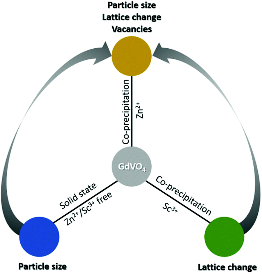 | ||
| Scheme 1 Elucidating and quantifying the role of lattice parameters and particle size in UC luminescence of GdVO4. Replacing Gd3+ with Sc3+ enables a reduction in cell volume, whereas change of synthesis method from precipitation to solid-state results in larger particles. Finally, comparing each of these systems in isolation with Zn2+ doped samples also provides some insight into the role of structural defects (oxygen vacancies). | ||
2. Experimental details
2.1 Materials
Gd(NO3)3·6H2O (≥99.9%), Er(NO3)3·6H2O (≥99.9%), Yb(NO3)3·6H2O (≥99.9%), ScCl3·6H2O (≥99.9%), Zn(NO3)2·6H2O (≥99%), CdCl2 (≥99.9%), and polyvinylpyrrolidone (PVP; mw 40![[thin space (1/6-em)]](https://www.rsc.org/images/entities/char_2009.gif) 000) were all purchased from Sigma-Aldrich and used without further purification. Na3VO4 and NH4VO3 (≥99%) was acquired from Acros Organics and used as received. For solid state synthesis, the respective oxides of Gd2O3, Er2O3, Yb2O3, and NH4VO3 (all ≥ 99%) were purchased from Sigma-Aldrich and used without further purification.
000) were all purchased from Sigma-Aldrich and used without further purification. Na3VO4 and NH4VO3 (≥99%) was acquired from Acros Organics and used as received. For solid state synthesis, the respective oxides of Gd2O3, Er2O3, Yb2O3, and NH4VO3 (all ≥ 99%) were purchased from Sigma-Aldrich and used without further purification.
2.2 Synthesis
In a typical co-precipitation synthesis, sodium vanadate was dissolved in water (4 mM) and designated as solution A. Similarly, the remaining metals salts and PVP were dissolved in an equal volume of water and labelled as solution B. After complete dissolution, solution A was added to solution B in a dropwise manner under constant stirring. The transparent solution initially turned turbid followed by the formation of a white precipitate after a few minutes. The resulting mixture was allowed to stir for an additional 30 min to aid reaction completion. Thereafter, the stirring was switched-off and the solution was left undisturbed to allow the precipitate to sediment. The precipitate was collected using a centrifuge (6000 rpm, 5 min) and washed several times with deionized water to remove any unreacted reagents. Isopropanol was used for the final wash to aid in removal of excess moisture. The washed precipitate was dried at 80 °C overnight in a vacuum oven. The dried precipitate was ground using a mortar and pestle into a fine powder and calcined in air at varying temperatures using a muffle furnace (ramp rate 5 °C min−1). The calcined powder was ground again with a mortar–pestle and stored in polystyrene cuvettes for further analysis.For comparative analysis, a few batches were also prepared using solid-state reaction technique. Typically, all oxides were weighed in stoichiometric ratio with 5% excess ammonium metavanadate and ground together using mortar–pestle for 15 min. Thereafter, the ground powders were transferred to covered alumina crucibles and calcined in air at different temperatures using a muffle furnace (5 °C min−1). The calcined powders were washed repeatedly with dilute NaOH solution till all the unreacted vanadium pentoxide was removed, as indicated by the colour change of the phosphor from yellow to white. The washed powders were dried overnight at 80 °C in a vacuum oven. The dried powders were ground again to break any large agglomerations and stored in polystyrene cuvettes.
2.3 Characterization
Crystallinity and phase of the prepared samples were analysed using X-ray diffraction on a D2 phaser (Bruker 2nd gen) using Cu-Kα radiation (step size: 0.01°; dwell time: 1 s, 0.1 mm slit). Elemental composition of the calcined phosphors was confirmed by inductively coupled plasma optical emission spectroscopy (ICP-OES; iCAP 7600 DUO Thermofisher Scientific). About 20 mg of the sample (accuracy ± 0.05 mg) was dissolved in 8 ml nitric acid at 523 K for 12 h in the pressure digestion vessel DAB-2 (Berghof). The analysis of the elements was accomplished with four different calibration solutions and an internal standard (Sc, Y). The range of the calibration solutions did not exceed a decade. Three wavelengths of the elements have been used for calculation. Rietveld refinements were performed using FullProf software. Thompson-Cox-Hastings pseudo-Voigt function and Chebychev polynomial function were used to calculate Bragg peaks and background, respectively. All the parameters were selected for the last refinement, to ensure the minimum χ2 value. The crystallite size (τ) were calculated using the Debye–Scherrer equation in which values for k and λ were fixed at 0.8 and 0.15406 nm, respectively. The peak broadening at half maximum intensity (β) was calculated for the strongest diffraction peak (θ = 24.7°). An automatic function was used to fit the diffraction peaks to a Lorentzian profile for calculation of β. The fitting function was assumed to converge if the calculated value of R2 exceeded 0.95.
The microstructure of the calcined powders was imaged using a scanning electron microscope (SEM; Zeiss Supra 60VP) equipped with an SE-II detector. The samples were sputter coated with a thin layer of silver (∼10 nm) to aid the SEM imaging. Dynamic light scattering (DLS) analyses were performed on Litesizer 500 (Anton Paar GmbH) to determine the number and volume weighted particle size distribution of the prepared samples.
Standard optical measurements were performed on powders stored in polystyrene cuvettes. The calcined powders were transferred to polystyrene cuvettes and tapped repeatedly to compact the powders. These samples were excited using 980 nm continuous-wave (CW) laser diode (Thorlabs, L980P200). The PLQY measurements were performed using a custom-built optical setup with an integrating sphere (Labsphere, Ø15 cm, 3P-LPM-060-SL) and a CCD spectrometer (Avantes, AvaSpec-ULS2048 × 64TEC) irradiance calibrated using a calibration lamp (Ocean Optics, HL-3plus-INT-CAL-EXT). The relative error for PLQY measurement for repeatedly synthesized samples was found to be considerably large (±15%). This was attributed to the variation in degree of powder compaction within the cuvettes leading to diffuse reflectance and reabsorption of light, thereby resulting in variation of the calculated PLQY values. Despite several attempts to improve the repeatability of the packing density of powders within the cuvettes, this error could not be reduced. Raman spectra for the samples were acquired using a Raman spectrometer (i-Raman Plus, BW Tek) with 785 nm excitation.
3. Results
All nanoscale phosphors in this study were calcined in air at 850 °C for two hours, unless stated otherwise. The doping concentration of Er (2 mol%) emitter and Yb (10 mol%) sensitizer ions were selected based on previously published results.34 Attempts for a further optimization of Yb3+ and Er3+ doping concentrations were not undertaken as it is inconsequential for the present discussion. Owing to the large number of samples prepared in this study the following nomenclature has been adopted for easy identification: doping concentration (mol%) followed by the element. For example, Gd1–a–b–xYbaErbMxVO4 is designated as aYb/bEr/xM, where M = Zn2+ or Sc3+. Furthermore, microscale phosphors prepared by solid-state synthesis are further designated using the postscript (ss).3.1 GdVO4:Yb/Er
Fig. S1 (see the ESI†) displays the XRD plot of the 10Yb/2Er reference sample (defined as having no Zn2+ or Sc3+ co-dopants) calcined at 850 °C. All major peaks in the XRD data (except 43.5°) could be readily indexed to the tetragonal GdVO4 phase (JCPDS Card no. 17-0260). Presence of clearly defined diffraction peaks indicate that the prepared material is highly crystalline, whereas the slight broadening of the peaks themselves could be attributed to the small particle size. A SEM image of the as-prepared 10Yb/2Er sample (Fig. 1(a)) illustrates that the phosphor consists of spheroidal nanoparticles (<100 nm) exhibiting a relatively narrow size distribution. The particle size distribution was further determined using DLS (see Fig. S2, ESI†). The average particle size was measured to be 50 nm, along with the presence of some larger clusters with a size up to 800 nm. These larger clusters are likely stable agglomerates originating from significant necking in-between particles. However, the overall fraction of such agglomerates in the prepared sample was low. Fig. 1(b) displays the UC emission spectrum of 10Yb/2Er upon 980 nm laser excitation at a moderate power density of 15 W cm−2. A predominantly green emission was observed with peaks at 524 nm and 553 nm, corresponding to the 2H11/2 → 4I15/2 and 4S3/2 → 4I15/2 transitions in Er3+, respectively. Only a weak emission intensity was observed for the red (667 nm, 4F9/2 → 4I15/2) and near-infrared (800–850 nm, 4I9/2 → 4I15/2 and 2H11/2 → 4I13/2) regions, which are usually quite intense in Er3+-doped oxide phosphors.36,53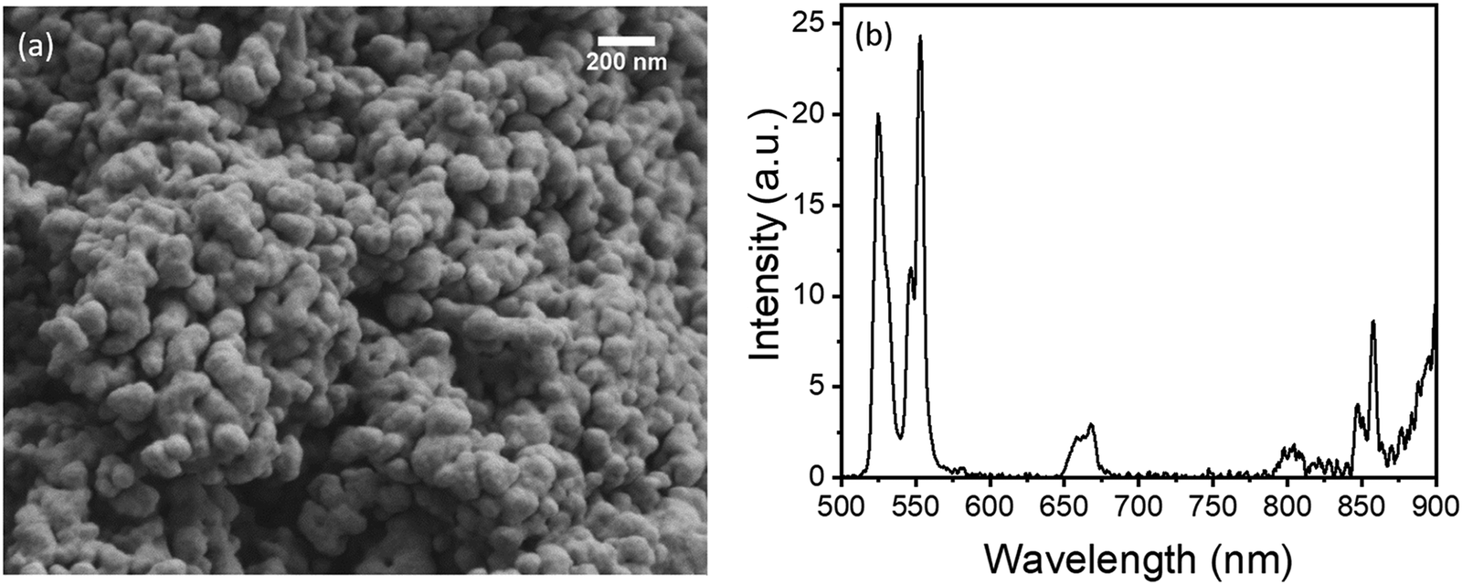 | ||
| Fig. 1 As-prepared GdVO4 reference sample doped with 10Yb/2Er: (a) SEM image; (b) UC emission spectrum, acquired under 980 nm excitation at a power density of 15 W cm−2. | ||
The measured value of the corresponding UC PLQY in 10Yb/2Er was very low (0.0029%). However, as proposed by Han et al.,14 this value can be substantially improved through the reduction of lattice parameters via doping. Hence, a series of Zn2+ co-doped samples were prepared to improve the luminescence.
3.2 GdVO4:Yb/Er/Zn
A range of samples was prepared with Zn2+ doping concentrations between 5–30 mol%. The 10Yb/2Er/xZn series of samples generally displayed increasing PLQY with increasing Zn2+ doping concentration (Fig. 2(a)). Together with the corresponding UC emission spectra (provided in Fig. S3, ESI†), the results clearly show that both the peak emission intensity (@ 553 nm) and the absolute PLQY values are improved by more than an order of magnitude even for low Zn2+ co-doping (5 mol%). Apart from the compelling improvement in optical properties, Zn2+-doped samples displayed no apparent shift in either the positions of the UC emission peaks or in their mutual intensity ratios. This confirms that Zn2+ is an optically inert dopant and the increase in luminescence does not originate from a change in the energy transfer pathways between Yb3+ and Er3+ ions.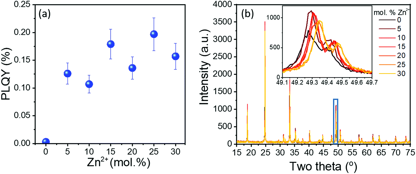 | ||
| Fig. 2 10Yb/2Er/xZn (x = 0–30) series of samples, all calcined at 850 °C: (a) UC PLQY values, acquired under 980 nm excitation at a power density of 15 W cm−2 and (b) the corresponding XRD data. Inset in (b) shows a magnified view of the highlighted section. | ||
The XRD data of the 10Yb/2Er/xZn series is provided in Fig. 2(b). It was observed that up to 25 mol% Zn2+, the diffraction pattern of the co-doped samples resembles that of the tetragonal GdVO4 phase. However, beyond 25 mol% three distinct peaks (at 31.8°, 34.5°, and 36.3°) corresponding to ZnO could be observed (Fig. S4, ESI†), indicating possible phase separation. Additionally, the progressive shift of diffraction peaks towards a higher Bragg angle (Fig. 2(b) inset) suggests a reduction of the lattice parameters. Hence, the lattice parameters for the 10Yb/2Er/xZn series of samples were calculated by refinement of the XRD data and are presented in Table S1 (ESI†). Rietveld analysis reveals the progressive reduction in lattice volume of the co-doped samples with increasing Zn2+ content. This reduction in lattice volume alongside with the increase in particle size, as evident from the SEM images provided in Fig. 3, could help to explain the sharp increase in the UC performance.
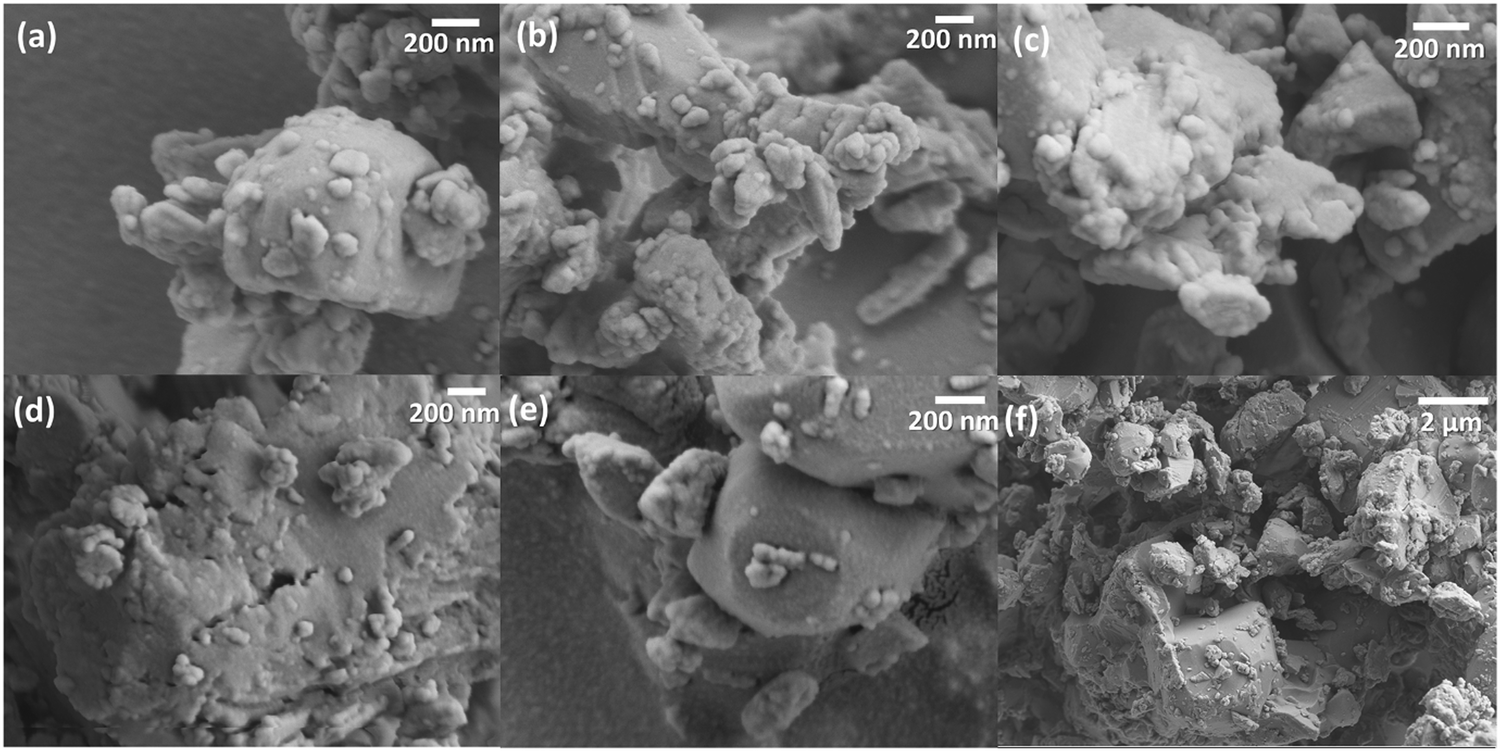 | ||
| Fig. 3 (a–e) Representative SEM images for 10Yb/2Er samples containing 5, 10, 15, 20, and 25 mol% Zn2+, respectively, with all samples calcined at 850 °C. (f) Low-magnification SEM image for 10Yb/2Er/15Zn. | ||
Compared to the reference sample (Fig. 1(a)), the 10Yb/2Er/xZn samples do not display any uniform nanostructure. Contrarily, the individual particles now resemble large polyhedrons ranging in size from <100 nm to over several μm. The presence of sharp edges and well-defined facets denotes that rapid crystal growth rates are achieved at 850 °C upon the addition of Zn2+. A possible reason for this could be the formation of crystals of zinc vanadate (Zn3V2O8), which is a well-known dielectric glass-forming material with a composition-dependent melting point between 800–1200 °C.54,55 Hence, calcination of Zn2+ co-doped samples at 850 °C would lead to the creation of a molten phase resulting in high crystal growth rates. Further confirmation for this hypothesis was also observed in the Raman spectra (Fig. S5, ESI†). Apart from the usual Raman modes for GdVO4, a comparative analysis of the Raman spectra of 10Yb/2Er/15Zn with the reference 10Yb/2Er revealed the presence of two additional peaks at 324 cm−1 and 850 cm−1. These peaks correspond to the asymmetric and symmetric O–V–O stretching in Zn3V2O8, respectively.56,57 A list of all observed Raman modes along with their description have been provided in Table S2 (ESI†). To further understand the effect of flux formation, a series of 10Yb/2Er/15Zn samples were prepared by calcination at various temperatures ranging from 600 °C to 800 °C at a 50 °C interval. All further analyses were limited to 10Yb/2Er/15Zn, as it afforded a considerable increase in UC luminescence without exhibiting phase separation.
It is clearly visible from UC PLQY values (Fig. 4(a)) and corresponding UC spectra (Fig. S6, ESI†) that the calcination temperature has a strong effect on the UC performance of 10Yb/2Er/15Zn. Only a very weak optical signal was obtained from the sample calcined at 600 °C with a steady improvement thereafter. Furthermore, both the brightness and PLQY increase linearly with temperature up to 700 °C. However, a change in calcination temperature from 700 °C to 750 °C is accompanied with a sudden rise in UC PLQY. Beyond 750 °C there is only a minor improvement in the UC luminescence with increasing calcination temperature. The corresponding XRD data in Fig. 4(b) provides some insight into this behaviour. It is evident from the XRD data that the sample calcined at 600 °C has poor crystallinity as confirmed by the broad shape and low intensity of its diffraction peaks. The diffraction peaks get steadily sharper and more intense as the temperature increases up to 700 °C. However, the relatively broad size of the peaks still indicates the presence of nanostructure. This observation changes completely at 750 °C with the evolution of intense and narrow diffraction peaks implying the presence of larger crystallites.
 | ||
| Fig. 4 10Yb/2Er/15Zn series of samples calcined at 600–850 °C (50 °C interval): (a) enhancement factor and absolute values for UC PLQY (980 nm excitation at 15 W cm−2) as a function of temperature. The blue spheres correspond to the actual PLQY value (%), whereas the black spheres represent gain in PLQY compared to the reference 10Yb/2Er sample. (b) Corresponding XRD data as a function of calcination temperature. Inset in (b) shows the magnified view for the highlighted region. Representative SEM images for samples calcined at (c) 600 °C, (d) 650 °C, (e and f) 700 °C, (g) 750 °C, and (h) 800 °C. | ||
However, the most compelling proof for the evolution of microstructure is provided by the corresponding SEM images in Fig. 4(c–h). These images confirm that samples prepared at 600 °C and 650 °C consist mainly of nanoparticles with an average size of <100 nm. At 700 °C the average size increases to above 100 nm with the presence of a few larger crystals. At 750 °C the nanostructure disappears almost completely and is replaced with micron and sub-micron polyhedrons with well-defined edges and sizes ranging from 0.3–2 μm. Notably, at 800 °C the ratio of micron to sub-micron particles increases considerably, whereas only microparticles remain upon calcination at 850 °C (Fig. 3(e and f)). This observation was also supported by the DLS measurements (Fig. S7, ESI†). The details of the optical measurements along with calculated lattice volume and crystallite sizes for all samples in this study are summarized in Table S3 (ESI†).
3.3 GdVO4:Yb/Er/Sc
A range of Sc3+-doped samples (10Yb/2Er/xSc; x = 5–25) were also prepared in order to achieve a reduction of the lattice parameters without a concomitant increase in particle size. Fig. 5(a) displays the UC PLQY values of the prepared samples as a function of Sc3+ concentration with the corresponding emission spectra provided in Fig. S8 (ESI†). Similar to Zn2+, Sc3+-doping did not induce any change in the position of UC emission lines or the mutual ratio of their intensities, thereby confirming the similarity of energy transfer pathways. However, the UC luminescence was improved considerably. Compared to the reference, the PLQY improved by ∼5 × for 10Yb/2Er/5Sc. This value was further increased to ∼20 × for 10Yb/2Er/10Sc, after which it appears to plateau. The XRD patterns for the entire 10Yb/2Er/xSc series are provided in Fig. 5(b). The lack of any anomalous or unidentified peaks in the XRD further confirms a high compatibility of Sc3+ in the parent vanadate phase. | ||
| Fig. 5 10Yb/2Er/xSc (x = 0–25) series of samples, all calcined at 850 °C: (a) enhancement factor and absolute values for UC PLQY (980 nm excitation at 15 W cm−2). The blue spheres correspond to the actual PLQY value (%), whereas the black spheres represent gain in PLQY compared to the reference 10Yb/2Er sample. (b) Corresponding XRD data. Inset in (b) shows a magnified view of the highlighted section. Representative SEM images for samples with (c) 10% and (d) 25% Sc3+. | ||
The XRD data also provides strong evidence for the reduction of lattice parameters. The diffraction peaks progressively shift towards higher Bragg angles with increasing Sc3+ concentration. Furthermore, the overall shift in the peaks is much more pronounced when compared to samples with equivalent Zn2+ doping (Fig. 2(b)). The corresponding lattice parameters calculated through Rietveld refinement (Table S4, ESI†) confirm that progressive incorporation of Sc3+ in GdVO4 matrix leads to a considerable shrinkage in cell volume. Furthermore, the reduction in lattice parameters is markedly higher than that observed for equivalent doping of Zn2+.
The lack of flux-effect (size enlargement) in Sc3+-doped samples was also confirmed by SEM images, as illustrated in Fig. 5(c and d). All Sc3+-doped samples exhibited an irregular-globular morphology. Furthermore, the size distribution appeared to deviate slightly from the highly monodisperse 10Yb/2Er, as regular appearance of larger particles (>100 nm) could be confirmed in the SEM images. The corresponding measurement of particle-size distribution (Fig. S9, ESI†) not only confirm that the average particle size was comparable to 10Yb/2Er, but also reveal the presence of stable agglomerates in the prepared samples. Nevertheless, the majority of the particles in all cases were observed to be ≤100 nm.
3.4 GdVO4:Yb/Er(ss)
A series of 10Yb/2Er(ss) samples were also prepared by using conventional solid-state synthesis. Literature suggests the usage of higher temperatures and longer calcination times with intermediate re-grinding for solid-oxide synthesis of GdVO4 microparticles.30 However, to obtain a comparative analysis with other samples prepared in this study, a similar calcination time (2 hours) and procedure were used. Furthermore, to explore the effect of temperature on UC, a range of samples were prepared between 850–1150 °C with an interval of 100 °C. Fig. 6(a) displays the UC PLQY values for 10Yb/2Er(ss) as a function of temperature. The corresponding emission spectra are provided in Fig. S10 (ESI†). Even for a similar calcination temperature (850 °C), the brightness and PLQY value for 10Yb/2Er(ss) was found to be ∼30 × larger than the reference sample that was prepared by co-precipitation method (10Yb/2Er; 850 °C). Additionally, UC luminescence improved linearly with temperature reaching a maximum value at 1050 °C after which it appears to be saturated. The maximum PLQY value for sample calcined at 1050 °C was found to be ∼52 × larger than the reference. | ||
| Fig. 6 GdVO4:Yb/Er(ss) samples calcined at 850–1150 °C (100 °C interval): (a) enhancement factor and absolute values for UC PLQY (980 nm excitation at 15 W cm−2) as a function of calcination temperature. The blue spheres correspond to the actual PLQY value (%), whereas the black spheres represent gain in PLQY compared to the reference 10Yb/2Er sample. (b) Corresponding XRD data. Inset in (b) shows a magnified view of the highlighted section. Representative SEM images for 10Yb/2Er(ss) calcined at (c) 850, (d) 950, (e) 1050, and (f) 1150 °C. | ||
The XRD data provided in Fig. 6(b) is a perfect match with that of reference sample, indicating the presence of tetragonal GdVO4 phase. Furthermore, the diffraction peaks were observed to get progressively sharper with increased calcination temperature, indicating the presence of larger crystallites. SEM imaging confirmed that solid-state reaction route leads to the creation of large and well-separated micro-particles (see Fig. 6(c–f)). Moreover, the DLS data (Fig. S11, ESI†) reveals that sample calcined at 850 °C consists of particle size ranging from 0.5 to 4 μm with a larger ratio of sub-micron particles. However, median particle size increased progressively with increasing temperature (1.2 μm at 950 °C, 1.8 μm at 1050 °C, and 2.1 μm at 1150 °C; Fig. S11, ESI†). Finally, the results from the ICP-OES elemental composition analysis for all samples in this study are presented in Table S5 (ESI†). Data in Table S5 (ESI†) clearly demonstrates that all the elements in the calcined samples are close to their stoichiometric coefficients.
4. Discussion
4.1 Role of Zn2+ co-doping in UC luminescence of GdVO4
Collation of the different optical and microstructural data from the various samples prepared in this study provides an interesting insight into the mechanics of UC luminescence. Primarily, the increase in brightness and PLQY observed upon co-doping of GdVO4 with a d-block element such as Zn originates from the simultaneous action of several different mechanisms.First, there is the reduction in lattice parameters as suggested by the shift of diffraction peaks to higher Bragg angles (Fig. 2(b)). Rietveld refinement of the plots showing the experimental and calculated patterns alongside the difference and actual Bragg positions for 10Yb/2Er/xZn series of samples are provided in Fig. S12–S16 (ESI†). The corresponding structural data is listed Table S1 (ESI†). As stated earlier, Zn2+ (90 pm) is smaller than the host Gd3+ ion (∼105 pm) for the present (VIII) co-ordination geometry. Hence, incorporation of Zn2+ as a substitutional dopant at Gd3+ sites leads to a considerable reduction of the cell volume, which improves optical performance. However, in the case of Zn2+ co-doping, a stronger contribution clearly comes from particle size (flux effect). Ample evidence for this was provided by the 10Yb/2Er/15Zn samples calcined at different temperatures. The PLQY values for the 10Yb/2Er/15Zn samples (Table S3, ESI†) were found to be highly dependent on the resultant particle size and increased rapidly when moving from nanoparticles to sub-micron and later micron-sized particles. In this case, Zn2+ co-doping provides a highly mobile phase at elevated temperatures (≥700 °C) leading to rapid crystal growth rates and formation of larger particles. Notably, this effect may be unique to doping Zn2+ in a vanadate host as other chemistries – for example, oxides or silicates – with a higher calcination temperature might not afford the same benefits. However, for such materials other suitable means for increasing or controlling particle size may be investigated, as evidenced by its dominating effect on luminescence. Finally, substitutional doping of Zn2+ is also expected to produce other effects such as reduction of concentration quenching and introduction of oxygen vacancies. These effects could also play a non-negligible role in UC luminescence. However, as these mechanisms cannot be completely decoupled in the current (Zn2+ co-doped) material system, additional series of samples were prepared to isolate the effects of lattice shrinkage and particle size.
4.2 Sc3+ co-doping and effect of lattice shrinkage
For the present VIII co-ordination geometry, Sc3+ (87 pm) is even smaller than Zn2+ (90 pm). Hence, substitutional doping of Sc3+ produces a greater reduction in lattice volume (Fig. S17–S21 and Table S4, ESI†). Additionally, a similar oxidation state (+3) and crystal structure (tetragonal) as the parent material would minimize structural defects such as vacancies and lattice mismatch. Finally, absence of particle size enlargement through the ‘flux effect’ in Sc3+-doped samples enable the study of lattice reduction in isolation. Similar to Zn2+, Sc3+ incorporation also leads to an improvement in both brightness and PLQY values. However, the quantum yield increases by a maximum of ∼20 × with 10 mol% Sc3+ and remains relatively unchanged thereafter. This is an important observation considering that the lattice volume continues to decrease with higher Sc3+ concentration whereas the particle size remains fairly similar. Furthermore, the overall reduction in cell volume with Sc3+ co-doping is considerably larger than similar Zn2+co-doped samples. Hence, it is easy to infer that reduction in cell volume has a limited contribution towards improved UC luminescence (∼20 × in case of GdVO4).4.3 Solid-state samples and the effect of particle size
Next, the contribution through enlargement of particle size was isolated with the help of 10Yb/2Er(ss) series of samples prepared through solid-state synthesis. These samples possess similar chemical composition and lattice parameters as those of the reference sample, with the exception of having a much larger particle size (μm compared with nm). The effect of larger particles is clearly reflected in the increased UC luminescence. For example, PLQY value for 10Yb/2Er(ss) sample prepared at 850 °C is already 50% higher than the best Sc3+ co-doped sample and more than 30 × larger than the reference. This enhancement, owing to the lack of Zn2+ and Sc3+ co-dopants, could be singly attributed to the larger particle size. Furthermore, a pseudo-linear dependence is observed between the choice of calcination temperature (the resultant particle size is plotted in Fig. S11, ESI†) and the UC PLQY (see Fig. 6(a)) for 10Yb/2Er(ss) samples. As the mean particle size increases, the PLQY values follow a similar trend reaching a maximum value of 0.15% for sample synthesized at 1050 °C (avg. size ∼2 μm). This value is comparable to the best Zn2+ co-doped sample (0.18%; 10Yb/2Er/15Zn calcined at 850 °C). Hence, these results confirm the dominating role that particle size plays in UC luminescence. The nature of results also suggest that such observations are not unique to GdVO4 and are also expected in other inorganic phosphors.4.4 Comparative analysis and the possible role of structural defects
Finally, the 10Yb/2Er/xZn series of samples (calcined at 850 °C) afford an interesting observation. Zinc as a substitutional dopant with a +2 oxidation state in GdVO4 matrix is expected to generate structural defects such as oxygen vacancies. We speculate here that these vacancies might play a significant role in UC luminescence. However, a direct method for determining the role of oxygen vacancies in the current material system is challenging owing to the simultaneous presence of other effects namely reduction of cell volume and increase in particle size. Nevertheless, its effect can be estimated indirectly by a careful cross-examination of other samples prepared in this study. The primary requisite for such an analysis being comparative particle size and crystallinity. These conditions are partially satisfied by the reference 10Yb/2Er, 10Yb/2Er/xSc, and 10Yb/2Er/15Zn (650 °C) samples.For the reference sample (10Yb/2Er) a UC PLQY value of 0.003% is observed that improves by 10 × to 0.03% for 10Yb/2Er/15Zn (650 °C). From the 10Yb/2Er/xSc series of samples the closest match in terms of particle size and cell volume is found for 10Yb/2Er/5Sc with a PLQY value of 0.02%. Despite a larger reduction in cell volume, the comparable PLQY values of 10Yb/2Er/5Sc and 10Yb/2Er/15Zn (650 °C) suggest that oxygen vacancies induced by co-doping with Zn2+ could either be neutral or slightly beneficial effect towards UC luminescence. Prima facie, this observation appears to contradict conventional argument that defects such as vacancies result in luminescence quenching. However, further support for this observation comes from the 10Yb/2Er/xZn series of samples prepared at 850 °C. Even without the presence of a clear trend, it can be easily inferred that UC PLQY generally improves with higher co-doping of Zn2+. It is already established from the 10Yb/2Er/xSc series of samples that shrinking cell volume has a limited contribution towards improved UC luminescence. Furthermore, the overall lattice shrinkage with increasing Zn2+ is actually much lower than that achieved with Sc3+ co-doping. Hence, the increase in PLQY is possibly attributable to other concomitant factors observed with Zn2+ co-doping, which would include oxygen vacancies.
However, at this point it is important to emphasize that these inferences are very primitive, based on limited observations, and should be viewed with scepticism. For example, the counter-intuitive observations in the 10Yb/2Er/xZn samples could also arise from: (i) the difference between the size-distribution (micro/macro particles) of samples prepared at 850 °C, and (ii) a non-negligible role from other phenomenon such as the overall defect density and reduction in concentration quenching. Further in-depth analyses will be required to fully confirm the proposed hypothesis and uncover the role of structural defects on optical performance. This is challenging with the current set of material systems. However, efforts are already underway to design a new system that allows the generation of a controllable level of structural defects. Analysis of the nature and number of such defects and their effect on UC luminescence will be presented as a follow-up study.
5. Conclusions
This study attempted to isolate and study the underlying factors for improved upconversion luminescence observed in inorganic phosphors by co-doping with metal ions. Two major factors namely lattice shrinkage and particle size were isolated and analysed for their relative contributions. For this purpose, three different series of samples namely, Zn2+-doped, Sc3+-doped, and (Zn2+/Sc3+-free) micro-particles were selected. A ∼60 × improvement in UC PLQY could be achieved through Zn2+ co-doping, whereas Sc3+ co-doped samples showed a much smaller improvement (∼20 ×). Alternately, samples prepared using solid-state synthesis also exhibited much larger PLQY values (>30–50 ×).The collated results from this study enabled us to draw the following conclusions: (1) Metal co-doping often improves the UC luminescence through the simultaneous action of several factors such as lattice shrinkage and enlargement of particle size. (2) Reduction in lattice parameters plays a significant role towards improving luminescence. However, the overall magnitude of such improvement might be limited. (3) Particle size of the phosphor (flux effect) has a much stronger bearing on its UC abilities, and this effect could be several times larger (∼2.5 × here) than that achieved through reduction of lattice parameters. (4) For systems such as vanadates, in which co-doping may induce these effects simultaneously, care must be taken to recognize and report the particle size to avoid drawing erroneous conclusions based on other competing factors. Additionally, a careful analysis of the prepared samples also hints towards a possible beneficial effect arising from other factors such as structural defects. However, further experiments will be needed to fully confirm this hypothesis. Finally, the results from this study are expected to provide a roadmap for the synthesis of efficient phosphors through either the selection of several different approaches or based on their synergistic combination.
Conflicts of interest
There are no conflicts to declare.Acknowledgements
The authors gratefully acknowledge financial support of a Technology Transfer Project (N038) between KIT and Polysecure GmbH (Germany) as well as funding from the German Federal Ministry of Education and Research (BMBF) under the framework program “Research for Sustainable Development” (FONA3) on the topic “Plastics in the environment” with grants no. 033R195A-E (project “MaReK – marker-based sorting and recycling system for plastics packaging”). We thank Dr Thomas Bergfeldt and his team from the chemical analysis group at institute for applied materials – applied materials physics (IAM-AWP; KIT) for their help with ICP-OES analysis of the samples. Furthermore, the authors would like to acknowledge the financial support provided by the Helmholtz Association: (i) a Recruitment Initiative Fellowship for BSR; (ii) research Field Energy – Program Materials and Technologies for the Energy Transition – Topic 1 Photovoltaics; and (iii) the Helmholtz Energy Materials Foundry (HEMF) project. Finally, the authors would like to thank the following people from Polysecure GmbH for valuable discussions: Jochen Mösslein, Guojun Gao, and Dirk Wacker.References
- P. C. de Sousa Filho, J. Alain, G. Leménager, E. Larquet, J. Fick, O. A. Serra and T. Gacoin, J. Phys. Chem. C, 2019, 123, 2441–2450 CrossRef CAS.
- Y. Zhou, L. Li, F. Qin and Z. Zhang, Opt. Express, 2020, 28, 14366–14373 CrossRef CAS PubMed.
- Q. Sun, S. Wang, L. Sun, J. Liang, B. Devakumar and X. Huang, Mater. Today Energy, 2020, 17, 100448 CrossRef.
- E. Song, Y. Zhou, X. B. Yang, Z. Liao, W. Zhao, T. Deng, L. Wang, Y. Ma, S. Ye and Q. Zhang, ACS Photonics, 2017, 4, 2556–2565, DOI:10.1021/acsphotonics.7b00852.
- Y. Liu, J. Silver, R. J. Xie, J. Zhang, H. Xu, H. Shao, J. Jiang and H. Jiang, J. Mater. Chem. C, 2017, 5, 12365–12377, 10.1039/c7tc04168c.
- S. Sun, Q. Wei, Y. Huang, F. Yuan, F. Lou, D. Zhong, L. Zhang, Z. Lin and B. Teng, J. Mater. Chem. C, 2020, 8, 7104–7112, 10.1039/d0tc00709a.
- B. Zhang, L. Wang and F. Chen, Laser Photonics Rev., 2020, 14 Search PubMed.
- H. Huang, J. Chen, Y. Liu, J. Lin, S. Wang, F. Huang and D. Chen, Small, 2020, 16, 2000708 CrossRef CAS.
- H. Huang, F. Huang, L. Lin, Z. Feng, Y. Cheng, Y. Wang and D. Chen, ACS Appl. Mater. Interfaces, 2019, 11, 46379–46385 CrossRef CAS PubMed.
- G. Gao, A. Turshatov, I. A. Howard, D. Busko, R. Joseph, D. Hudry and B. S. Richards, Adv. Sustainable Syst., 2017, 1(5), 1600033, DOI:10.1002/adsu.201600033.
- Z. Wang, X. Fan, M. He, Z. Chen, Y. Wang, Q. Ye, H. Zhang and L. Zhang, J. Mater. Chem. B, 2014, 2, 7559–7566, 10.1039/c4tb01240b.
- J. Du and D. Poelman, J. Phys. Chem. C, 2020, 124, 16586–16595, DOI:10.1021/acs.jpcc.0c04875.
- C.-Y. Chou, M. Abdesselem, C. Bouzigues, M. Chu, A. Guiga, T.-H. Huang, F. Ferrage, T. Gacoin, A. Alexandrou and D. Sakellariou, Sci. Rep., 2017, 7, 44770 CrossRef CAS PubMed.
- S. Han, R. Deng, X. Xie and X. Liu, Angew. Chem., Int. Ed., 2014, 53, 11702–11715 CrossRef CAS PubMed.
- E. L. Cates, A. P. Wilkinson and J. H. Kim, J. Phys. Chem. C, 2012, 116, 12772–12778, DOI:10.1021/jp302515t.
- M. Yadav, M. Mondal, L. Mukhopadhyay and V. K. Rai, Methods Appl. Fluoresc., 2018, 6, 025001, DOI:10.1088/2050-6120/aa9e46.
- P. Cortelletti, M. Pedroni, F. Boschi, S. Pin, P. Ghigna, P. Canton, F. Vetrone and A. Speghini, Cryst. Growth Des., 2018, 18, 686–694 CrossRef CAS.
- A. Escudero, C. Carrillo-Carrión, M. V. Zyuzin, S. Ashraf, R. Hartmann, N. O. Núñez, M. Ocaña and W. J. Parak, Nanoscale, 2016, 8, 12221–12236, 10.1039/c6nr03369e.
- Q. Cheng, J. Sui and W. Cai, Nanoscale, 2012, 4, 779–784 RSC.
- C. Zhao, X. Kong, X. Liu, L. Tu, F. Wu, Y. Zhang, K. Liu, Q. Zeng and H. Zhang, Nanoscale, 2013, 5, 8084–8089 RSC.
- B. Zhang, J. Meng, X. Mi, C. Zhang, Z. Zhang and H. Zheng, RSC Adv., 2018, 8, 37618–37622 RSC.
- A. Kumar, J. C. G. E. da Silva, K. Kumar, H. C. Swart, S. K. Maurya, P. Kumar and S. P. Tiwari, Mater. Res. Bull., 2019, 112, 28–37 CrossRef CAS.
- Y. Wang, Z. Wen, W. Ye, Z. Feng, C. Zhao, C. Zuo, Y. Li, Z. Cao, Z. Cao, C. Ma and Y. Cao, J. Lumin., 2020, 221, 117029 CrossRef CAS.
- M. Sun, J. Liu and L. Nie, J. Alloys Compd., 2020, 816, 152575 CrossRef CAS.
- X. Yang, W. Ji, Z. Li, J. Chen, L. Liu, L. Hao, B. Dong, X. Xu, M. Liu, J. Liu, Y. Xia and S. Agathopoulos, Phys. Chem. Chem. Phys., 2020, 22, 2819–2826, 10.1039/c9cp06137a.
- R. Fu, Y.-Y. Hu, H.-N. Qiao, C.-L. Yang, H. Yin and M.-G. Ou, Rare Met., 2020, 40, 1–10, DOI:10.1007/s12598-020-01591-2.
- A. K. Choudhary, A. Dwivedi, A. Bahadur and S. B. Rai, J. Lumin., 2019, 210, 135–141 CrossRef CAS.
- B. P. Singh, A. K. Parchur, R. S. Ningthoujam, P. V. Ramakrishna, S. Singh, P. Singh, S. B. Rai and R. Maalej, Phys. Chem. Chem. Phys., 2014, 16, 22665–22676 RSC.
- P. K. Vishwakarma, A. Bahadur, A. Maurya and S. B. Rai, Mater. Res. Bull., 2019, 115, 219–226 CrossRef CAS.
- T. V. Gavrilović, D. J. Jovanović, V. M. Lojpur, V. Đorđević and M. D. Dramićanin, J. Solid State Chem., 2014, 217, 92–98 CrossRef.
- T. V. Gavrilović, D. J. Jovanović, L. V. Trandafilović and M. D. Dramićanin, Opt. Mater., 2015, 45, 76–81 CrossRef.
- K. Park, J. Kim, K. Y. Kim, J. Y. Kim, Y. Kim and S. J. Dhoble, J. Rare Earths, 2013, 31, 13–17 CrossRef CAS.
- Y. Yan, W. Zhang, B. Ren, L. Zhong and Y. Xu, Ionics, 2017, 23, 869–875 CrossRef CAS.
- T. V. Gavrilović, D. J. Jovanović, V. Lojpur and M. D. Dramićanin, Sci. Rep., 2014, 4, 4209 CrossRef PubMed.
- E. L. Cates, A. P. Wilkinson and J. H. Kim, J. Phys. Chem. C, 2012, 116, 12772–12778 CrossRef CAS.
- I. Kamińska, K. Fronc, B. Sikora, M. Mouawad, A. Siemiarczuk, M. Szewczyk, K. Sobczak, T. Wojciechowski, W. Zaleszczyk, R. Minikayev, W. Paszkowicz, P. Stępień, P. Dziawa, K. Ciszak, D. Piątkowski, S. Maćkowski, M. Kaliszewski, M. Włodarski, J. Młyńczak, K. Kopczyński, M. Łapiński and D. Elbaum, RSC Adv., 2015, 5, 78361–78373 RSC.
- M. K. Mahata, T. Koppe, T. Mondal, C. Brüsewitz, K. Kumar, V. Kumar Rai, H. Hofsäss and U. Vetter, Phys. Chem. Chem. Phys., 2015, 17, 20741–20753 RSC.
- G. Chen, H. Liu, H. Liang, G. Somesfalean and Z. Zhang, J. Phys. Chem. C, 2008, 112, 12030–12036 CrossRef CAS.
- S. L. Cates, E. L. Cates, M. Cho and J.-H. Kim, Environ. Sci. Technol., 2014, 48, 2290–2297 CAS.
- E. L. Cates and F. Li, RSC Adv., 2016, 6, 22791–22796 RSC.
- A. Navrotsky, W. Lee, A. Mielewczyk-Gryn, S. V. Ushakov, A. Anderko, H. Wu and R. E. Riman, J. Chem. Thermodyn., 2015, 88, 126–141 CrossRef CAS.
- J. Sokolnicki, Mater. Chem. Phys., 2011, 131, 306–312 CrossRef CAS.
- E. Harju, I. Hyppänen, J. Hölsä, J. Kankare, M. Lahtinen, M. Lastusaari, L. Pihlgren and T. Soukka, Z. Krist. Proc., 2011, 1, 381–388 Search PubMed.
- O. A. Savchuk, J. J. Carvajal, C. Cascales, J. Massons, M. Aguiló and F. Díaz, J. Mater. Chem. C, 2016, 4, 6602–6613 RSC.
- Y. Liang, H. M. Noh, J. Xue, H. Choi, S. H. Park, B. C. Choi, J. H. Kim and J. H. Jeong, Mater. Des., 2017, 130, 190–196 CrossRef CAS.
- V. Mahalingam, C. Hazra, R. Naccache, F. Vetrone and J. A. Capobianco, J. Mater. Chem. C, 2013, 1, 6536–6540 RSC.
- B. H. Min and K. Y. Jung, RSC Adv., 2019, 9, 20002–20008 RSC.
- G. Zhu, L. Chen, F. Zeng, L. Gu, X. Yu, X. Li, J. Jiang, G. Guo, J. Cao, K. Tang, H. Zhu, H. E. Daldrup-Link and M. Wu, ACS Omega, 2019, 4, 15806–15814 CrossRef CAS.
- X. Kang, D. Yang, P. Ma, Y. Dai, M. Shang, D. Geng, Z. Cheng and J. Lin, Langmuir, 2013, 29, 1286–1294 CrossRef CAS PubMed.
- W. Yin, L. Zhou, Z. Gu, G. Tian, S. Jin, L. Yan, X. Liu, G. Xing, W. Ren, F. Liu, Z. Pan and Y. Zhao, J. Mater. Chem., 2012, 22, 6974–6981 RSC.
- D. Geng, G. Lozano and H. Míguez, ACS Appl. Mater. Interfaces, 2019, 11, 4219–4225, DOI:10.1021/acsami.8b17368.
- T. Nakajima, M. Isobe, Y. Uzawa and T. Tsuchiya, J. Mater. Chem. C, 2015, 3, 10748–10754, 10.1039/c5tc01929j.
- G. Gao, D. Busko, S. Kauffmann-Weiss, A. Turshatov, I. A. Howard and B. S. Richards, J. Mater. Chem. C, 2017, 5, 11010–11017 RSC.
- U. Hoppe, R. Kranold, E. Gattef, J. Neuefeind and D. A. Keen, Z. Naturforsch., A: Phys. Sci., 2001, 56, 478–488, DOI:10.1515/zna-2001-0609.
- A. Ghosh, S. Bhattacharya and A. Ghosh, J. Alloys Compd., 2010, 490, 480–483, DOI:10.1016/j.jallcom.2009.10.050.
- W. H. Low, P. S. Khiew, S. S. Lim, C. W. Siong, C. H. Chia and E. R. Ezeigwe, J. Alloys Compd., 2019, 784, 847–858 CrossRef CAS.
- S. Rajkumar, E. Elanthamilan and J. P. Merlin, J. Alloys Compd., 2021, 861, 157939 CrossRef CAS.
Footnote |
| † Electronic supplementary information (ESI) available: The article is accompanied by a single file containing the supporting information for results reported in the main text. See DOI: 10.1039/d1tc03205d |
| This journal is © The Royal Society of Chemistry 2021 |