 Open Access Article
Push–pull thiophene-based small molecules with donor and acceptor units of varying strength for photovoltaic application: beyond P3HT and PCBM†
Martina
Marinelli‡
a,
Andrea
Candini‡
 bc,
Filippo
Monti‡
 b,
Alex
Boschi
 b,
Mattia
Zangoli
 *bc,
Elisabetta
Salatelli
 a,
Filippo
Pierini
 d,
Massimiliano
Lanzi
 a,
Alberto
Zanelli
 b,
Massimo
Gazzano
 b and
Francesca
Di Maria
 *bc
*bc
aDepartment of Industrial Chemistry “Toso Montanari”, University of Bologna, Viale Risorgimento 4, 40136 Bologna, Italy
bCNR-ISOF, Via P. Gobetti 101, 40129-Bologna, Italy. E-mail: mattia.zangoli@isof.cnr.it; francesca.dimaria@isof.cnr.it
cCLAN-Center for Light Activated Nanostructures, Università di Bologna and CNR, Via Gobetti 101, 40129 Bologna, Italy
dDepartment of Biosystems and Soft Matter, Institute of Fundamental Technological Research, Polish Academy of Sciences, ul. Pawinskiego 5B, 02-106 Warsaw, Poland
First published on 3rd August 2021
Abstract
Here is reported an expedient synthesis implementing enabling technologies of a family of thiophene-based heptamers alternating electron donor (D) and acceptor (A) units in a D–A′–D–A–D–A′–D sequence. The nature of the peripheral A groups (benzothiadiazole vs. thienopyrrole-dione vs. thiophene-S,S-dioxide) and the strength of the donor units (alkyl vs. thioalkyl substituted thiophene ring) have been varied to finely tune the chemical-physical properties of the D–A oligomers, to affect the packing arrangement in the solid-state as well as to enhance the photovoltaic performances. The optoelectronic properties of all compounds have been studied by means of optical spectroscopy, electrochemistry, and density functional theory calculations. Electrochemical measurements and Kelvin probe force microscopy (KPFM) predicted a bifunctional behaviour for these oligomers, suggesting the possibility of using them as donor materials when blended with PCBM, and as acceptor materials when coupled with P3HT. Investigation of their photovoltaic properties confirmed this unusual characteristic, and it is shown that the performance can be tuned by the different substitution pattern. Furthermore, thanks to their ambivalent character, binary non-fullerene small-molecule organic solar cells with negligible values of HOMO and LUMO offsets were also fabricated, resulting in PCEs ranging between 2.54–3.96%.
Introduction
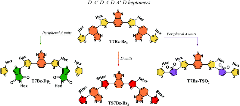
The exploration of novel organic semiconductive materials for the development of bulk heterojunction (BHJ) solar cells has led to considerable progress in device performance in the past years.1–3 The careful design of chemical structures, which takes advantage of the input provided by the continuous effort of synthetic chemists, together with a better understanding of the relationship between structure, properties, and performance are driving the development of increasingly high-performing organic photovoltaic materials.4–7 Indeed, power conversion efficiencies (PCEs) of organic solar cells are now above 18%, confirming the role of BHJs as a promising technology for future clean energy supply.8,9 In this context, great attention has been devoted to the design of small molecules, which if compared to their polymer counterparts present many advantages: (i) well-defined molecular structures, (ii) precise molecular weights, (iii) high purity without batch-to-batch variations (iv) solubility in non-chlorinated solvents.10–13 The current molecular design is based on the push–pull concept, in which electron donor (D) and electron acceptor (A) units are covalently linked and alternated along the conjugated backbone.14–16 The different nature of the D and A fragments allows modulating the shift of electron density from the D to the A moiety achieving a fine control of the optoelectronic properties such as a wider absorption range of the solar emission spectrum.17–22 Furthermore, well-engineered molecular moieties may help in guiding the morphology of the active layer thus eliciting suitable phase separation, one of the most demanding tasks to achieve high efficiency in BHJ.23 Over the years, different push–pull small molecules, characterized by a wide diversity in the alternation of the D and A functional units, such as D–A, D–A–A′, A–D–A, D–A–D sequence, have been synthesized to be employed as donors counterpart in blend with fullerene-based acceptors.24–28 Recently, researchers have also focused their attention on synthesizing small molecules capable of substituting fullerene derivatives to overcome the pitfalls related to their use – that include expensive synthesis, difficult tunability of the energy gap, and scarce absorption in the visible spectrum – thus allowing for the fabrication of non-fullerene small molecule organic solar cells (NF-SM OSCs).29,30 In this scenario, thiophene-based derivatives have a prominent role since they represent a unique class of compounds that have been proved to fulfill both the role of donor and acceptor materials or even that of single materials in BHJ solar cells.31–37 Interestingly, it has also been reported that some push–pull thiophene-based oligomers can display a bifunctional photovoltaic behavior, i.e., they can be employed both as a D material when blended with PCBM or as an A when combined with a D compound such as P3HT.38–40 This peculiar behaviour has been scarcely reported in the literature, as most photoactive materials exhibit only unipolar photovoltaic properties, i.e., they work either as donors or acceptors. Here, we report the synthesis and characterization of a novel class of D–A′–D–A–D–A′–D co-oligomers that can be applied, depending on the active material partner, for the fabrication of different BHJ solar cells. Four oligomers (heptamers) with different D and peripheral A units were engineered. It was varied either the strength of the D unit by replacing alkylated thiophene units (T7Bz-Bz2) with thioalkylated thiophenes (T7SBz-Bz2), or the peripheral A moieties by substituting the benzothiadiazole units with thienopyrrole-dione (T7Bz-Dp2) or thiophene S,S-dioxide moieties (T7Bz-TSO2) (Chart 1).The effects of the different substitution patterns (i.e., the presence of additional sulfur atoms attached to alkyl chains or the combination of different acceptor units) on the electronic properties in the solid state, as well as on their packing and nanoscale blend morphologies were investigated. Different characterization techniques, including X-ray diffraction (XRD), differential scanning calorimetry (DSC), UV-vis spectroscopy, cyclic voltammetry (CV), Kelvin probe force microscopy (KPFM) and atomic force microscopy (AFM) were employed for this purpose. Furthermore, density functional theory (DFT) calculations enabled to gain a deeper understanding concerning the electronic properties of the investigated materials at the molecular level.
We show that this family of heptamers presents multiple capabilities of working as active materials in BHJ solar cells either as donor material in blend with PCBM or as acceptor in blend with P3HT. Furthermore, we report that couples of oligomers with small HOMO [ΔE(HOMO)offset: −0.01 to 0.00 eV] and LUMO offsets [ΔE(LUMO)offset: 0.07–0.11 eV] can be employed for the realization of binary NF-SM OSCs,41–43 using non-chlorinated solvent for their deposition. Finally, the environmentally friendly approach employed for the deposition of the oligomeric blends allows achieving higher BHJ performance when compared to cells deposited from chlorinated solvent.
Results and discussion
Synthesis and characterization of heptamers
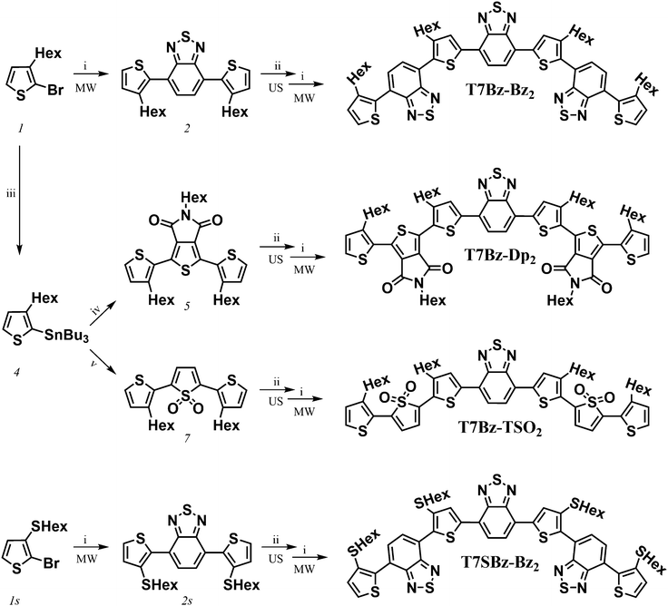
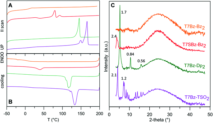
Scheme 1 shows the synthetic pattern employed for the preparation of push–pull heptamers characterized by a D–A sequence. Benzothiadiazole (Bz), thienopyrrole-dione (Dp) or thiophene S,S-dioxide (TSO) moieties were employed as A unit, while hexyl (Hex) or thiohexyl (SHex) substituted thiophene ring as D unit. As depicted in Scheme 1, all synthetic steps, except for the lithiation of compound 2, take advantage of enabling technologies. In particular, ultrasound (US) assistance for bromination reactions and microwave (MW) irradiation for Suzuki and Stille cross-coupling reactions. In agreement with what was reported in previous works, these techniques allow to (i) radically improve reaction yields, (ii) lower reaction times from hours to minutes, and (iii) work in environment-friendly conditions using water as co-solvent.44–46 In the final step, all heptamers, which differ for the peripheral A units or for the presence of an extra sulfur atom in the side chains of the D group, were obtained in yield ranging from 60 to 70% after 20 min of MW irradiation. The presence of hexyl side chains on the four thiophene rings guarantees good solubility of all molecules in DCM, toluene, and THF, particularly for T7Bz-Dp2, which has additional hexyl side chains installed on the Dp units. The details of the synthesis are reported in ESI.†DSC analysis was performed to obtain information on the effects of the substitution pattern on the materials’ thermal characteristics and to provide guidelines for device optimization. Table S1 (ESI†) summarizes the transition temperatures and their enthalpy values. DSC analysis revealed that the thermal properties of the heptamers are deeply influenced by the nature of the D and A units present in the molecular structure (Fig. 1A and B).
T7Bz-Bz2 exhibit only a glass transition (Tg) suggesting its persistence in an amorphous state over all the investigated temperature range. Remarkably, the introduction of sulfur atoms in the side chains of the D moieties (T7SBz-Bz2) or the replacement of the peripheral A units (T7Bz-Dp2, T7Bz-TSO2) results in DSC plots characterized by one or two endothermic transitions. In particular, the presence of TSO groups as peripheral A units shifts the endothermic processes to a higher temperature (Table S1, ESI†). Note that, for all compounds, the observed transitions occur far below their thermal decompositions which are higher than 250 °C (see TGA analysis in ESI†). To better evaluate the nature of the different phases, XRD analysis was performed. The diffraction profiles of the films of the investigated materials are reported in Fig. 1C. The room temperature XRD pattern of T7Bz-Bz2 confirms its amorphous nature since no sharp peaks are observed. In T7SBz-Bz2, the presence of sulfur atoms in the alkyl chains of the thiophene units induces a partial order, indeed the diffraction profile shows only one peak (2.4 nm) as usual for mesomorphic materials.47 Substitution of the peripheral A units of T7Bz-Bz2 with Dp or TSO appears to induce a higher propensity to form ordered arrays. Indeed, the pattern obtained after replacing peripheral Bz units with Dp shows only three peaks at 5.3°, 10.5°, 15.8°, all belonging to a periodicity of 1.7 nm, suggesting the presence of a highly oriented film or a layer ordered smectic system. On the other hand, exchanging the Bz units with TSO brings to a fully tridimensional array, indeed, the XRD T7Bz-TSO2 pattern is characteristic of a crystalline material.
The combination of calorimetric and XRD data allows a better insight into the solid-state morphology of the materials. With respect to T7Bz-Bz2, the T7SBz-Bz2 sample presents multiple endothermic processes, with the first endotherm peak at 81 °C (ΔH = 14.24 J g−1) bigger than the second one at 93 °C (ΔH = 4.01 J g−1) (Table S1, ESI†). Since XRD reveals only one peak roughly correspondent to the molecular length, absent in T7Bz-Bz2, and DFT calculation suggest that the molecule presents a bent geometry resembling that of a banana (see below) – well known for promoting the organization in liquid crystalline phases48 – a transformation between mesomorphic phases before melting can be hypothesized. This result highlights the importance of the extra sulfur atom in the side chains, which through S⋯S non-covalent intermolecular interactions favors an extra long-range ordering in T7SBz-Bz2.45,46,49 Replacing the peripheral Bz unit with Dp and TSO induces an increase in the crystalline character of the compounds. The Dp units in T7Bz-Dp2 promote a long-range (layer) order, as evidenced by the appearance of an endothermic peak at 146 °C relatives to the melting of the material, in a fully reversible process, as confirmed by the exothermic peak in cooling scan corresponding to its crystallization. The presence of Dp probably enforces backbone co-planarity via intermolecular S⋯O interactions leading to close π–π stacking in the solid-state.50 In compound T7Bz-TSO2, the TSO units determine a double endothermic transition that can be ascribed to melt/recrystallization processes involving defective crystals during the DSC scan, or to the existence of a high-temperature phase, which is not markedly different from the crystalline phase present at room temperature since the heat exchange is quite small (ΔHm = 2.95 J g−1).
DFT electronic structure calculations
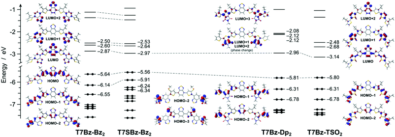
DFT calculations reveal that all the heptamers have a large number of conformers that can be populated at room temperature. To get a deeper understanding of such structural freedom, a conformational analysis has been carried out on trimers constituting the investigated heptamers (Scheme S5 and Fig. S20, ESI†). Although this analysis merely takes into account the conformational freedom for the isolated molecule without considering any intramolecular interactions, such as π–π interactions, chain interdigitations, etc., it can qualitatively elucidate experimental finding. For instance, the presence of sulfur atoms in the alkyl chains nearby the Bz units (as in 2s, the precursor of T7SBz-Bz2) strongly destabilizes the anti conformations, in which the sulfur electron density is forced to interact with the nitrogen lone pairs of the Bz unit (i.e., syn/anti ratio of 72/28 at 298 K, see Table S2, ESI†). On the contrary, the absence of sulfur-functionalized side chains (as in 2, the precursor of T7Bz-Bz2) strongly reduces this effect and the syn and anti conformers are nearly isoenergetic, leading to the presence of a plethora of thermally accessible conformers at room temperature and, most probably, explaining the amorphous nature of T7Bz-Bz2 in contrast to the partial order found in T7SBz-Bz2 (see the previous section). An even more pronounced effect is observed when the Bz unit is replaced by TSO (as in 7, the precursor of T7Bz-TSO2). Indeed, the strong intramolecular S⋯O interactions between the sulfonyl group of the TSO unit and the neighboring thiophene rings are able to strongly stabilize the syn conformers (i.e., syn/anti ratio of 75/25 at 298 K); notably, this stabilization is maximized in C2 symmetry which favors the formation of two S⋯O interactions, instead of a single S⋯O⋯S one as in the Cs group (see Table S2, ESI†).51 The presence of a well-defined minimum conformation can indeed be a reason for the higher degree of crystallinity observed experimentally in T7Bz-TSO2 (see DSC and XRD characterizations). Differently, the introduction of the Dp unit does not induce any significant intramolecular stabilization despite its high coplanarity and the presence of carbonyl and amide groups.Fig. 2 shows the frontier molecular orbitals of the lowest-energy conformer of each of the investigated heptamers. For all molecules, the HOMO is mainly located on the central D–A–D unit, which is more or less stabilized depending on the different peripheral A units. In particular, the presence of the electron-donating sulfur atoms in the alkyl chains of T7SBz-Bz2 induces a slight HOMO destabilization, if compared to the pristine T7Bz-Bz2 heptamer (i.e., +0.08 eV). On the contrary, the presence of the strongly electron-accepting peripheral units in T7Bz-Dp2 and T7Bz-TSO2 is capable of inducing a HOMO stabilization of 0.16 and 0.15 eV, respectively.
The LUMO of all heptamers is predominantly located on the lowest π* molecular orbital of the central Bz moiety, with some degree of delocalization to the nearby units. As in the case of HOMO, the LUMO energy can be tuned along with the series roughly depending on the acceptor strength of the peripheral moieties (i.e., T7Bz-TSO2 < T7Bz-Dp2 ≈ T7SBz-Bz2 < T7Bz-Bz2). It is worth noting that, for all the investigated molecules, while the LUMO is localized on the central acceptor moiety, the LUMO+1 and the LUMO+2 are predominantly located on the peripheral acceptors, with the latter generally having a greater delocalization on the central Bz as well (see Fig. 2).
Electro-optical characterizations
Fig. S23 (ESI†) shows the cyclovoltammetry of the heptamers in solution, and thin film and Table 1 reports their redox potentials, HOMO and LUMO energy levels, and energy gaps.| E ox | E red | E ox | E red | HOMOb | LUMOb | E g | λ abs | λ abs | |
|---|---|---|---|---|---|---|---|---|---|
| a Solution. b Thin film (Eox and Erid in V; HOMO, LUMO and Eg in eV; λ in nm). | |||||||||
| T7Bz-Bz2 | +1.10 | −1.18 | +1.08 | −1.19 | −5.76 | −3.49 | 2.27 | 318, 492 | 320, 490 |
| T7Bz-Dp2 | +1.17 | −1.08 | +0.90 | −1.23 | −5.58 | −3.45 | 2.13 | 380, 498 | 380, 494 |
| T7Bz-TSO2 | +1.16 | −0.96 | +0.89 | −1.05 | −5.57 | −3.63 | 1.94 | 316, 522 | 315, 533 |
| T7SBz-Bz2 | +0.92 | −1.12 | +0.90 | −1.12 | −5.58 | −3.56 | 2.02 | 318, 510 | 320, 515 |
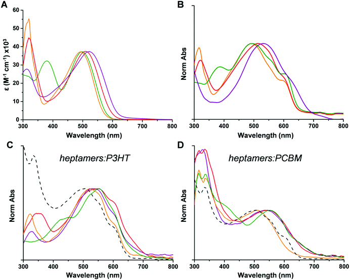
As shown in Table 1, increasing the strength of the donor units (Hex vs. SHex), results in a significant shift in the oxidation and reduction potentials both in solution and thin film. Indeed, compared to T7Bz-Bz2, T7SBz-Bz2 exhibits an oxidation wave shifted towards less positive potentials (180 mV both in solution and in thin film) and the reduction ones towards less negative potentials (60 mV in solution and 70 mV in thin film). These results are in good agreement with the HOMO destabilization and the LUMO stabilization estimated by DFT calculations on T7SBz-Bz2, if compared to pristine T7Bz-Bz2 (see above). Furthermore, in thin films, the two oligomers show the same redox potentials of the molecules in solution, indicating that neither conformation changes nor orbital staking occurs. This result agrees with both XRD measurements, as these heptamers provide amorphous or low crystalline films, and absorption spectra. Replacing the peripheral acceptor units of Bz with Dp or TSO affects redox potentials depending on the strength of the A units and the packing arrangement.52 In solution, both T7Bz-Dp2 and T7Bz-TSO2 result to be more difficult to oxidize and easier to reduce than T7Bz-Bz2. In detail, T7Bz-Dp2 shows oxidation and reduction waves shifted by 70 and 100 mV, respectively. Similarly, T7Bz-TSO2 shows a shifted oxidation wave of 60 mV at more positive potentials and a reduction wave that is remarkably shifted by 220 mV to a less negative potential. Such experimental findings match well with the scenario already depicted by DFT calculation, considering dichloromethane solvation effects. Conversely, in thin film, their redox potentials strongly differ from the solution because of the molecular packing. Indeed, T7Bz-TSO2 and T7Bz-Dp2, which after deposition in thin film give crystalline films, show less positive oxidation potentials and less negative reduction potentials than in solution. This induces a consequent shortening of the Eg as a result of a π–π* staking in the crystals (Table 1). Notably, a comparison of the HOMO/LUMO energy levels of the heptamers with those of P3HT and PCBM highlights that LUMO levels of these compounds lie in an energetic position whereby electron transfer can occur either from P3HT or to PCBM (Fig. S24, ESI†). The absorption spectra reflect the trend of the Eg determined by CV measurements. All compounds, both in solution and thin film, exhibit the typical behaviour of alternating D–A conjugated molecules with a two-band absorption profile in the UV-visible region relative to internal charge-transfer (ICT) and π → π* transition processes.53 As shown in Fig. 3, ICT absorption bands are susceptible to variations in the D or A groups. Indeed, the ICT maxima shift to higher wavelengths when different A units are present (TSO-Bz >Dp-Bz > Bz-Bz) or by increasing the electron-donating effect of the donor groups (SHex > Hex) (Table 1). The heptamers exhibit similar molar extinction coefficients (ε) of ∼3.7![[thin space (1/6-em)]](https://www.rsc.org/images/entities/char_2009.gif) ×
× ![[thin space (1/6-em)]](https://www.rsc.org/images/entities/char_2009.gif) 104
104 ![[thin space (1/6-em)]](https://www.rsc.org/images/entities/char_2009.gif) M−1 cm−1 (Fig. 3A and Table S8, ESI†).
M−1 cm−1 (Fig. 3A and Table S8, ESI†).
TD-DFT calculations, carried out at the same level of theory used for ground-state optimizations, are able to qualitatively reproduce the absorption profiles of all heptamers, despite a general underestimation of around 0.4 eV, if vertical transition energies are directly compared to experimental absorption maxima (Fig. S21a, ESI†). This phenomenon can be attributed to the important charge-transfer contribution associated with such transitions, which can be better taken into account by increasing the amount of Hartree–Fock exchange in the functional.54 Indeed, when M06-2X is used, the agreement with experimental data is excellent (Fig. S21b, ESI†); anyway, only minor differences have been observed in the nature of the transitions calculated either by M06 or M06-2X functional, the latter leading only to more multiconfigurational excitations. For all the heptamers, the intense and unstructured absorption band in the region between 450 and 600 nm is almost exclusively attributed to a nearly pure HOMO → LUMO excitation, leading to the population of S1 (Tables S3–S6, ESI†). In the case of T7Bz-TSO2, a distinct shoulder is experimentally observed next to S0 → S1 absorption band, at approx. 450 nm. This transition is due to the S0 → S2 excitation, attributed to a charge transfer from the thiophene donors to the lateral TSO acceptors (Table S6, ESI†). It is worth mentioning that TD-DFT calculations were also able to predict the presence of the second broad and unstructured absorption band around 350–440 nm, which is present only in the spectrum of T7Bz-Dp2. This band is attributed to an envelope of four vertical excitations (i.e., from S0 to S2–S5) that are basically CT transitions from the lateral thiophene units to either the 5-membered thiadiazole ring (S2 and S3) or the Dp ones (S4 and S5, Table S5, ESI†). As reported in Fig. S25 (ESI†), the heptamers exhibit a broad fluorescence band in the region between 550 nm and 750 nm with quantum yield in the range of ∼1–38% (see details in ESI†). In thin film, the maximum absorption spectra of all heptamers remain approximately the same as in solution (Fig. 3B); additionally, band broadening and vibronic structuration suggest that solid-state organization promotes a better packing within molecules, particularly for T7Bz-Dp2 and T7Bz-TSO2. Indeed, TD-DFT calculations indicate a general flattening of all heptamers upon excited-state relaxation on S1 (Fig. S22 and Table S7, ESI†). When blended with either P3HT or PCBM, the maxima of the thin film absorption spectra remain approximately the same and result to be red-shifted compared to the P3HT:PCBM blend, unveiling an enhancement of visible spectral coverage when using the heptamer (Fig. 3C and D). Analogously to P3HT:PCBM blend, the emission is significantly quenched, thus indicating that effective photoinduced charge transfer occurs between the heptamer and PCBM or P3HT (Fig. S27, ESI†).
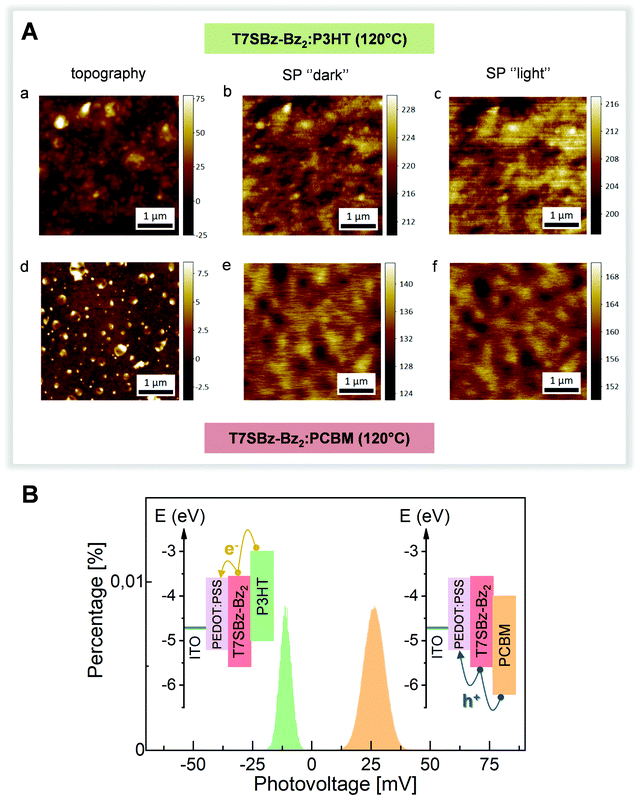
KPFM measurements
The possibility of using these heptamers as both D and A materials was tested by KPFM in two model organic solar cells systems, made of ITO/PEDOT:PSS/on top of which a thick layer of T7SBz-Bz2 blended with P3HT or PCBM, respectively, was deposited (see ESI†). KPFM allows imaging the surface potential (SP) distribution of the system under investigation (that is the difference between the tip and the sample work function (WF): SP = WFtip − WFsample), simultaneously with the topographic information acquired in the conventional AFM mode.55,56 By investigating the sample before and after illumination, the measured changes of the SP values are indicative of the charge distribution induced by light excitation and whether and which carriers are exchanged with the substrate. Fig. 4A shows the topography and corresponding SP (under dark and illumination conditions) images of T7SBz-Bz2 blended with P3HT (upper panels) and with PCBM (lower panels). The blend with P3HT exhibits an amorphous and rough morphology with the presence of clusters with a size of tens of nanometers (Fig. 4A(a)). The clusters have a higher SP value (Fig. 4A(b)) and hence a lower WF, thus they are associated with P3HT crystal domains. Similarly, the T7SBz-Bz2 compound is amorphous also in the blend with PCBM (Fig. 4A(d)), which forms round-shaped regions of approximately 200–300 nm of diameter, presenting the expected lower value of SP as shown in Fig. 4A(e). When the systems are measured under illumination with a halogen lamp (Fig. 4A(c, f)), an evident shift of the average SP values for each blend is observed; interestingly, the changes have an opposite sign, i.e., the SP upon illumination decreases in the case of the P3HT blend, while it increases when the oligomer is mixed with PCBM.This observation can be understood by considering the HOMO/LUMO energy levels alignment between the materials (see Fig. 4B, inset): for each blend, the charge exchange between the photoactive material and the substrate is favored only for one type of carriers and hindered for the others. When the P3HT (PCBM) is present, electrons (holes) are exchanged towards the PEDOT:PSS/ITO electrode, leaving the blend with an excess of holes (electrons) and hence a negative (positive) surface photovoltage SPV (i.e., the SP difference between the light and dark condition) is measured. This picture is schematized in Fig. 4B, where the histogram distribution of the SPV values is shown for the two blends, along with the corresponding HOMO/LUMO energy levels alignments. These measurements confirm the bifunctional nature of the heptamers and the possibility of using them as both D and A materials. Finally, the absence of clear charge separation between the materials of the blends may be ascribed to the fact that a thick film is being investigated, in agreement with previous reports on other organic photovoltaic cells.57
Photovoltaic properties
To evaluate the bifunctional photoactive behaviour of the heptamers, air-manufactured BHJ organic solar cells with a ITO/PEDOT:PSS/active layer/Al configuration were fabricated. The active layers were constituted of a 1![[thin space (1/6-em)]](https://www.rsc.org/images/entities/char_2009.gif) :
:![[thin space (1/6-em)]](https://www.rsc.org/images/entities/char_2009.gif) 1 weight ratio blend of the heptamers with either PCBM or P3HT employed as A and D derivatives, respectively. The photovoltaic performance parameters for the prepared devices are listed in Table 2, while the corresponding J–V features of the best-performing solar cells and external quantum efficiency (EQE) curves are reported in Fig. 5.
1 weight ratio blend of the heptamers with either PCBM or P3HT employed as A and D derivatives, respectively. The photovoltaic performance parameters for the prepared devices are listed in Table 2, while the corresponding J–V features of the best-performing solar cells and external quantum efficiency (EQE) curves are reported in Fig. 5.
| PCBM | P3HT | |||||||||
|---|---|---|---|---|---|---|---|---|---|---|
| J sc | J sc | V oc | FF | PCE | J sc | J sc | V oc | FF | PCE | |
| a J sc from EQE (Jsc in mA cm−2; FF and PCE in %; Voc in V.). | ||||||||||
| T7Bz-Bz2 | 6.46 ± 0.2 | 7.28 | 0.62 ± 0.01 | 0.48 ± 0.04 | 1.91 ± 0.13 | 5.35 ± 0.3 | 3.83 | 0.46 ± 0.01 | 0.45 ± 0.05 | 1.11 ± 0.17 |
| T7Bz-Dp2 | 5.91 ± 0.1 | 4.96 | 0.60 ± 0.01 | 0.45 ± 0.06 | 1.60 ± 0.15 | 5.55 ± 0.4 | 2.88 | 0.48 ± 0.01 | 0.46 ± 0.06 | 1.22 ± 0.13 |
| T7Bz-TSO2 | 6.41 ± 0.3 | 5.58 | 0.52 ± 0.01 | 0.55 ± 0.06 | 1.83 ± 0.11 | 5.27 ± 0.2 | 4.80 | 0.42 ± 0.01 | 0.56 ± 0.04 | 1.24 ± 0.21 |
| T7SBz-Bz2 | 11.42 ± 0.4 | 9.65 | 0.58 ± 0.01 | 0.65 ± 0.07 | 4.32 ± 0.16 | 5.02 ± 0.5 | 4.55 | 0.43 ± 0.01 | 0.48 ± 0.05 | 1.04 ± 0.19 |
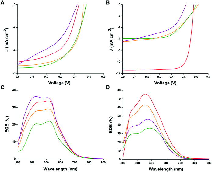 | ||
| Fig. 5 J–V and EQE curves of the cells prepared with blends of heptamers:P3HT (A–C) and heptamers:PCBM (B–D) (orange line T7Bz-Bz2; red line T7SBz-Bz2; green line T7Bz-Dp2; purple line T7Bz-TSO2). | ||
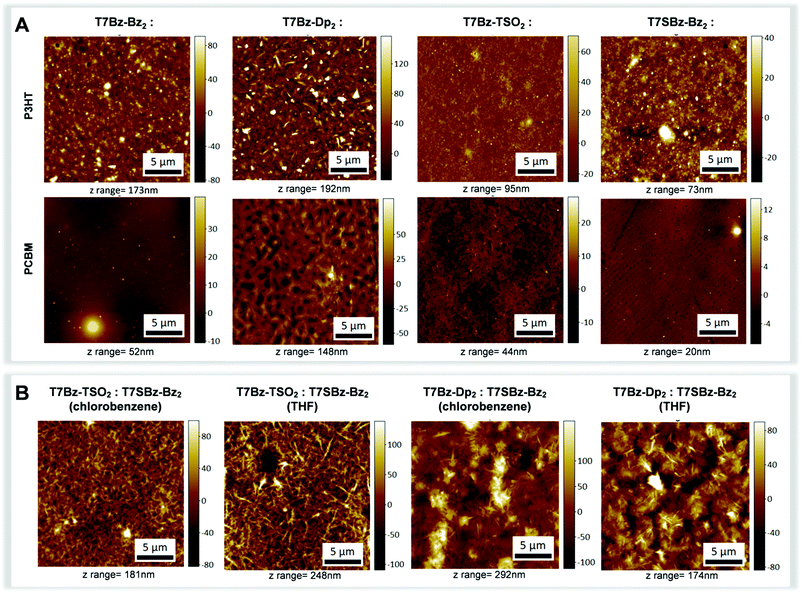
All blend samples were subjected to AFM, WAXS and grazing incidence WAXS (GIWAXS) measurements in order to correlate morphological investigations with structural data. As far as structural features are concerned, XRD patterns of the blends formed with T7Bz-Bz2 and T7SBz-Bz2 and PCBM are featureless (Fig. S28, ESI†), indicative of an amorphous state. In contrast, the XRD profiles of the blends of T7Bz-Dp2 and T7Bz-TSO2 with PCBM show sharp peaks – with periodicities ascribable to the same distances of the pristine films as reported in Fig. 1C – indicating that the PCBM does not perturb the aggregation modality of the oligomers, which keep forming ordered structures in the blend. Notably, both WAXS and GIWAXS measurements, which allow to highlight parallel and perpendicular planes to the sample surface, respectively, give similar results. According to Scherrer analysis, crystalline domains in the range of 47–60 nm for T7Bz-Dp2 and 20–26 nm for T7Bz-TSO2 are formed (Table S11, ESI†). Further investigations of the morphology of the active layers were performed through AFM measurements (Fig. 6). All PCBM blended films exhibit similar thicknesses on the order of ∼200 nm (Table S9, ESI†). However, those formed with T7Bz-Bz2 and T7SBz-Bz2 appear to be more uniform and smoother (with root-mean-square (RMS) surface roughness values of 2 nm) compared to those embedding T7Bz-Dp2 and T7Bz-TSO2, which are rather coarse (RMS values of 4 and 16 nm, respectively). AFM images show that the blend of T7SBz-Bz2 and PCBM presents round-shaped dark regions of ∼200–300 nm constituted by domains of PCBM, while in T7Bz-Dp2 and T7Bz-TSO2 blends, crystalline domains of the heptamers with needle-like shape are present in agreement with XRD measurements (Fig. 6A). The phase segregation observed in all the blends formed by the heptamers with PCBM is generally considered a valuable characteristic in BHJ. Indeed, it can lead to a higher interfacial area between D and A domains, enhancing exciton dissociation.58,59 The measured BHJs performances suggest that the exclusive crystallinity of the donor material does not result in high PCE efficiency, whereas the presence of nanoscopic PCBM aggregates may favourably affect the performances. This can be rationalized considering that PCBM aggregation can prevent charge recombination while promoting the generation of free, extractable charges.59,60
The external quantum efficiencies (EQE) of all cells (Fig. 5C and D) were also used for calculation of Jsc, obtaining data consistent with the experimental findings (see Table 2), thus confirming the best performance of the devices prepared with T7SBz-Bz2 and T7Bz-TSO2, when blended with PCBM and P3HT, respectively. Additionally, the EQE profiles follow the trend observed in the UV-Vis spectra of heptamers in thin film (Fig. 3C and D), indicating that the whole absorption effectively contributes to the photocurrent.
![[thin space (1/6-em)]](https://www.rsc.org/images/entities/char_2009.gif) :
:![[thin space (1/6-em)]](https://www.rsc.org/images/entities/char_2009.gif) 1 weight ratio blend with either T7Bz-TSO2 (LUMO eV −3.63) or T7Bz-Dp2 (LUMO eV −3.45), working as A and D species, respectively. Additionally, thanks to the absence of fullerene derivatives and the optimal solubility and miscibility of the heptamers in a non-chlorinated solvent, the devices were also processed from THF, in addition to chlorobenzene as the formerly used solvent. The relative thin film absorption spectra are reported in Fig. S26 (ESI†). In both T7SBz-Bz2:T7Bz-TSO2 and T7SBz-Bz2:T7Bz-Dp2 blends, the absorption spectra of thin films deposited from THF are red shifted of ∼20 nm compared to those deposited from chlorobenzene, hence evidencing a reduced optical band gap. The photovoltaic characteristics of the devices, having the previously adopted device configuration ITO/PEDOT:PSS/active layer/Al, are reported in Table 3 and the corresponding J–V plots of the best-performing cells in Fig. S30 (ESI†).
1 weight ratio blend with either T7Bz-TSO2 (LUMO eV −3.63) or T7Bz-Dp2 (LUMO eV −3.45), working as A and D species, respectively. Additionally, thanks to the absence of fullerene derivatives and the optimal solubility and miscibility of the heptamers in a non-chlorinated solvent, the devices were also processed from THF, in addition to chlorobenzene as the formerly used solvent. The relative thin film absorption spectra are reported in Fig. S26 (ESI†). In both T7SBz-Bz2:T7Bz-TSO2 and T7SBz-Bz2:T7Bz-Dp2 blends, the absorption spectra of thin films deposited from THF are red shifted of ∼20 nm compared to those deposited from chlorobenzene, hence evidencing a reduced optical band gap. The photovoltaic characteristics of the devices, having the previously adopted device configuration ITO/PEDOT:PSS/active layer/Al, are reported in Table 3 and the corresponding J–V plots of the best-performing cells in Fig. S30 (ESI†).
| T7Bz-TSO2 | T7Bz-Dp2 | |||||||
|---|---|---|---|---|---|---|---|---|
| J sc | V oc | FF | PCE | J sc | V oc | FF | PCE | |
| (Jsc in mA cm−2; FF and PCE in %; Voc in V) | ||||||||
| T7SBz-Bz2 chlorobenzene | 7.43 ± 0.3 | 0.58 ± 0.01 | 0.59 ± 0.04 | 2.54 ± 0.16 | 8.93 ± 0.4 | 0.60 ± 0.01 | 0.58 ± 0.04 | 3.11 ± 0.18 |
| T7SBz-Bz2 THF | 8.01 ± 0.2 | 0.57 ± 0.01 | 0.59 ± 0.05 | 2.69 ± 0.19 | 10.81 ± 0.5 | 0.61 ± 0.01 | 0.60 ± 0.03 | 3.96 ± 0.17 |
The bifunctionality of these push–pull thiophene-based small molecules, i.e., T7SBz-Bz2, is further proved by obtaining interesting and promising PCE values ranging between 2.54–3.96%. This is of particular regard, considering the potential use of a non-chlorinated and less harmful solvent such as THF. Fig. 6B reports the AFM of the blends, which present an anisotropic morphology independently from the solvent employed (i.e., THF or chlorobenzene). Diffraction profiles of the heptamer:heptamer blends indicate that the crystalline component is constituted by T7Bz-Dp2 or T7Bz-TSO2 with a size in the range of 47–63 nm (Fig. S29 and Table S12, ESI†). Note that the formation of crystalline domains is considered favorable in NF-SM OSCs as it avoids excessive intermixing between D and A materials thus overcoming the problems related to the charge recombination in blend films.62,63 Furthermore, thin films deposited from THF show a lower thickness compared to those deposited from chlorobenzene whose roughness is related to the dimension of the formed crystals (Table S10, ESI†).
It is important to note that these couples of D:A heptamers present negligible values of ΔE(HOMO)offset (0 and −0.01 eV for T7SBz-Bz2:T7Bz-Dp2 and T7SBz-Bz2:T7Bz-TSO2, respectively) and ΔE(LUMO)offset (0.11 and 0.07 eV for T7SBz-Bz2:T7Bz-Dp2 and T7SBz-Bz2:T7Bz-TSO2, respectively) (see Fig. S24, ESI†). It has recently been shown that having fullerene-free organic solar cells with a low HOMO and LUMO offset between D/A blend could be a tool to improve the OSC efficiencies. Indeed, it was found that the small driving force for charge separation resulting from these ΔEoffset close to zero allows ultrafast charge transfer and a suppression of the energy losses that hinder the device performances.41–43
Finally, the Voc values measured for heptamer:heptamer blends result to be lower than expected from CV/optical measurements. This suggests that further optimization of the active layer can potentially lead to better performance.64,65 In this regard, we expect that higher efficiencies can be achieved through the optimization of processing conditions – e.g., by varying D/A weight ratio, selecting the solvent or mixed solvent, adding solid additives, changing deposition techniques – as well as employing multiple post-treatment methods, including vacuum drying, solvent annealing, and thermal annealing.64–67 Furthermore, as recently reported, optimizing the device architecture through the introduction of organic electron transport layers (ETLs) could be a goal to realize highly efficient NF-SM OSCs.68
Conclusions
In this study, we synthesized and characterized a new family of thiophene-based small molecules with a D–A′–D–A–D–A′–D sequence. An extensive study of the influence of the different substitution pattern – induced either by introducing an extra sulfur atom in the side chains or by varying the strength of the acceptor unit (benzothiadiazole vs. diketopirrole vs. thiophene-S,S-dioxide) – on the variation of the chemical-physical properties is reported. In addition, a multiple approach including X-ray diffraction, thermal analysis and DFT calculations has been employed to investigate the aggregation features of the oligomers. A greater tendency to form ordered arrays was observed when non-covalent intra- and intermolecular interactions, such as S⋯S, or S⋯O, are present in the molecule. Cyclic voltammetry combined with KPFM measurements allowed to identify that these heptamers present a bifunctional photoactive behaviour, as they can be employed either as donor or acceptor materials when blended with PCBM or P3HT, respectively. Furthermore, we demonstrated that thanks to their bifunctional photoactivity, binary NF-SM OSCs can be prepared by blending distinct heptamers with different electron affinities. In this case, PCE efficiency of 2.54–3.96% can be achieved despite very low HOMO and LUMO offsets which nevertheless guarantee the operation of the device. Our work highlights that further exploration of novel pairs of donor and acceptor thiophene based small molecules from the point of view of their energy levels, morphology, and surface potential (SP) distribution can be useful to provide guidelines for the design of future multifunctional materials and increase the performances of NF-SM OSCs devices.Author contributions
FM conducted DFT analysis and analyzed the data. AC and AB carried out AFM and KPFM measurements. MG made XRD measurements and analyzed the data. MZ and FDM prepared and characterized the heptamers. AZ carried out CV experiments. ES made thermal analysis. MM, ML prepared and characterized BHJ solar cells. FP performed EQE analysis. MZ contributed to the writing of the paper. FDM coordinated the project and wrote the paper with inputs from the other authors. All authors have approved the final version of the manuscript.Conflicts of interest
There are no conflicts to declare.Acknowledgements
FDM and MZ acknowledge the UE project INFUSION (Engineering optoelectronic INterfaces: a global action intersecting FUndamental conceptS and technology implementatION of self-organized organic materials, Proposal number: 734834). FP thanks the National Centre for Research and Development (NCBiR) for the financial support via the LIDER program (NCBiR grant no. LIDER/28/0067/L-7/15/NCBR/2016). This work was partially supported by the Italian MIUR (PRIN 20173L7W8K).Notes and references
- K. A. Mazzio and C. K. Luscombe, Chem. Soc. Rev., 2015, 44, 78 RSC.
- A. Wadsworth, Z. Hamid, J. Kosco, N. Gasparini and I. McCulloch, Adv. Mater., 2020, 32, 2001763 CrossRef CAS PubMed.
- W. Liu, X. Xu, J. Yuan, M. Leclerc, Y. Zou and Y. Li, ACS Energy Lett., 2021, 6, 598 CrossRef CAS.
- P. Cheng and Y. Yang, Acc. Chem. Res., 2020, 53, 218 CrossRef PubMed.
- Y. Che, Y. Zhang, Y. Yang, C.-H. Liu, R. Izquierdo, S. S. Xiao and D. F. Perepichka, J. Org. Chem., 2020, 85, 52 CrossRef CAS PubMed.
- Y. Zhou, Y. Qin, C. Ni and Y. Xie, J. Appl. Polym. Sci., 2020, 137, e49006 CrossRef.
- E. Salatelli, M. Marinelli, M. Lanzi, S. Dell’Elce, A. Liscio, M. Gazzano and F. Di Maria, J. Phys. Chem. C, 2018, 122, 4156 CrossRef CAS.
- Q. Liu, Y. Jiang, K. Jin, J. Qin, J. Xu, W. Li, J. Xiong, J. Liu, Z. Xiao, K. Sun, S. Yang, X. Zhang and L. Din, Sci. Bull., 2020, 65, 272 CrossRef CAS.
- L. Zhan, S. Li, X. Xia, Y. Li, X. Lu, L. Zuo, M. Shi and H. Chen, Adv. Mater., 2021, 33, 2007231 CrossRef CAS PubMed.
- R. Zhou, Z. Jiang, C. Yang, J. Yu, M. A. Adil, D. Deng, W. Zou, J. Zhang, K. Lu, W. Ma, F. Gao and Z. Wei, Nat. Commun., 2019, 10, 5393 CrossRef PubMed.
- B. Yadagiri, K. Narayanaswamy, S. Revoju, B. Eliasson, G. D. Sharma and S. P. Singh, J. Mater. Chem. C, 2019, 7, 709 RSC.
- H. Tran, M. Haris, T. Ahn and S. K. Lee, Mol. Cryst. Liq. Cryst., 2020, 705, 35 CrossRef CAS.
- B. Kan, Y. Kan, L. Zuo, X. Shi and K. Gao, InfoMat, 2021, 3, 175 CrossRef CAS.
- X. Wan, C. Li, M. Zhang and Y. Chen, Chem. Soc. Rev., 2020, 49, 2828 RSC.
- K. He, P. Kumar, Y. Yuan and Y. Li, Mater. Adv., 2021, 2, 115 RSC.
- A. Armin, W. Li, O. J. Sandberg, Z. Xiao, L. Ding, J. Nelson, D. Neher, K. Vandewal, S. Shoaee, T. Wang, H. Ade, T. Heumuller, C. Brabec and P. Meredith, Adv. Energy Mater., 2021, 11, 20003570 CrossRef.
- M. E. Kose, J. Phys. Chem. A, 2012, 116, 12503 CrossRef CAS PubMed.
- J. Du, M. C. Biewer and M. C. Stefan, J. Mater. Chem. A, 2016, 4, 15771 RSC.
- H. Cao, N. Bauer, C. Pang, J. Rech, W. You and P. A. Rupar, ACS Appl. Energy Mater., 2018, 1, 7146 CrossRef CAS.
- C. Zhao, F. Yang, D. Xia, Z. Zhang, Y. Zhang, N. Yan, S. You and W. Li, Chem. Commun., 2020, 56, 10394 RSC.
- S. UrRehman, A. Alam, S. Sadaf, S. R. Khan, M. Shoaib, A. Q. Khan, M. Khan and W. UrRehman, J. Mol. Model., 2020, 26, 154 CrossRef PubMed.
- D. Gedewaf, X. Pan and M. R. Andersson, Front. Mater., 2020, 7, 280 CrossRef.
- Z. Wang, K. Gao, Y. Kan, M. Zhang, C. Qiu, L. Zhu, Z. Zhao, X. Peng, W. Feng, Z. Qian, X. Gu, A. K.-Y. Jen, B. Z. Tang, Y. Cao, Y. Zhang and F. Liu, Nat. Commun., 2021, 12, 332 CrossRef CAS PubMed.
- B. Y. Antwi, R. G. D. Taylor, J. Cameron, R. B. Owoare, R. Kingsford-Adaboh and P. J. Skabara, RSC Adv., 2016, 6, 98797 RSC.
- Z. Wang, L. Zhu, Z. Shuai and Z. Wei, Macromol. Rapid Commun., 2017, 38, 1700470 CrossRef PubMed.
- P. Gautam, R. Sharma, R. Misra, M. L. Keshtov, S. A. Kuklin and G. D. Sharma, Chem. Sci., 2017, 8, 2017 RSC.
- Z. Zhang, J. Yuan, Q. Wei and Y. Zou, Front. Chem., 2018, 6, 414 CrossRef PubMed.
- S. Alam, M. S. Akhtar, Abdullah, E.-B. Kim, H.-S. Shin and S. Ameen, Appl. Sci., 2021, 11, 646 CrossRef CAS.
- J. Hou, O. Inganas, R. H. Friend and F. Gao, Nat. Mater., 2018, 17, 119 CrossRef CAS PubMed.
- A. Karki, A. J. Gillett, R. H. Friend and T.-Q. Nguyen, Adv. Energy Mater., 2020, 11, 2003441 CrossRef.
- B. C. Schroeder, R. S. Ashraf and I. McCulloch, Thiophene-Based High-Performance Donor Polymers for Organic Solar Cells, Wiley-VCH Verlag GmbH & Co. KGaA, 2014 Search PubMed.
- C. Duan, K. Gao, F. J. M. Colberts, S. C. J. Meskers, M. M. Wienk and R. A. J. Janssen, Adv. Energy Mater., 2017, 7, 1700519 CrossRef.
- T. Xu, Y. Chang, C. Yan, Q. Yang, Z. Kan, R. Singh, M. Kumar, G. Li, S. Lu and T. Duan, Sustainable Energy Fuels, 2020, 4, 2680 RSC.
- J. Liu, H. Lu, Y. Liu, J. Zhang, C. Li, X. Zu and Z. Bo, ACS Appl. Mater. Interfaces, 2020, 12, 10746 CrossRef PubMed.
- J. Pan, L. Wang, W. Chen, S. Sang, H. Sun, B. Wu, X.-C. Hang, Z. Sun and W. Huang, J. Mater. Chem. C, 2020, 8, 6749 RSC.
- M. Marinelli, M. Lanzi, A. Liscio, A. Zanelli, M. Zangoli, F. Di Maria and E. Salatelli, J. Mater. Chem. C, 2020, 8, 4124 RSC.
- F. Di Maria, M. Biasiucci, F. P. Di Nicola, E. Fabiano, A. Zanelli, M. Gazzano, E. Salatelli, M. Lanzi, F. Della Sala, G. Gigli and G. Barbarella, J. Phys. Chem. C, 2015, 119, 27200 CrossRef CAS.
- J. Song, X. Xue, B. Fan, L. Huo and Y. Sun, Mater. Chem. Front., 2018, 2, 1626 RSC.
- G. Qiu, Z. Jiang, Z. Ni, H. Wang, H. Dong, J. Zhang, X. Zhang, Z. Shu, K. Lu, Y. Zhen, Z. Wei and W. Hu, J. Mater. Chem. C, 2017, 5, 566 RSC.
- H. Shi, W. Fu, M. Shi, J. Ling and H. Chen, J. Mater. Chem. A, 2015, 3, 1902 RSC.
- J. Liu, S. Chen, D. Qian, B. Gautam, G. Yang, J. Zhao, J. Bergqvist, F. Zhang, W. Ma, H. Ade, O. Inganäs, K. Gundogdu, F. Gao and H. Yan, Nat. Energy, 2016, 1, 1 Search PubMed.
- H. Fu, Y. Wang, D. Meng, Z. Ma, Y. Li, F. Gao, Z. Wang and Y. Sun, ACS Energy Lett., 2018, 3, 2729 CrossRef CAS.
- S. Li, L. Zhan, C. Sun, H. Zhu, G. Zhou, W. Yang, M. Shi, C.-Z. Li, J. Hou, Y. Li and H. Chen, J. Am. Chem. Soc., 2019, 141, 3073 CrossRef CAS.
- M. Zangoli, M. Gazzano, F. Monti, L. Maini, D. Gentili, A. Liscio, A. Zanelli, E. Salatelli, G. Gigli, M. Baroncini and F. Di Maria, ACS Appl. Mater. Interfaces, 2019, 11, 16864 CrossRef CAS PubMed.
- F. Di Maria, M. Zangoli, I. Palamá, E. Fabiano, A. Zanelli, M. Monari, A. Perinot, M. Caironi, V. Maiorano, A. Maggiore, M. Pugliese, E. Salatelli, G. Gigli, I. Viola and G. Barbarella, Adv. Funct. Mater., 2016, 26, 6970 CrossRef CAS.
- F. Di Maria and G. Barbarella, J. Sulfur Chem., 2013, 34, 627 CrossRef CAS.
- M. Melucci, L. Favaretto, C. Bettini, M. Gazzano, N. Camaioni, P. Maccagnani, P. Ostoja, M. Monari and G. Barbarella, Chem. – Eur. J., 2007, 13, 10007 CrossRef.
- M. B. Ros, J. L. Serrano, M. R. de la Fuente and C. L. Folcia, J. Mater. Chem., 2005, 15, 5093 RSC.
- P.-S. Lin, Y. Shoji, S. N. Afraj, M. Ueda, C.-H. Lin, S. Inagaki, T. Endo, S.-H. Tung, M.-C. Chen, C.-L. Liu and T. Higashihara, ACS Appl. Mater. Interfaces, 2021, 13(27), 31898–31909 CrossRef CAS PubMed.
- C. Zhao, F. Yang, D. Xia, Z. Zhang, Y. Zhang, N. Yan, S. You and W. Li, Chem. Commun., 2020, 56, 10394 RSC.
- X. Zhang, Z. Gong, J. Li and T. Lu, Intermolecular Sulfur·Oxygen, J. Chem. Inf. Model., 2015, 55, 2138 CrossRef CAS PubMed.
- S. Canola, L. Mardegan, G. Bergamini, M. Villa, A. Acocella, M. Zangoli, L. Ravotto, S. A. Vinogradov, F. Di Maria, P. Ceroni and F. Negri, Photochem. Photobiol. Sci., 2019, 18, 2180 CrossRef CAS PubMed.
- S. Ellinger, K. R. Graham, P. Shi, R. T. Farley, T. T. Steckler, R. N. Brookins, P. Taranekar, J. Mei, L. A. Padilha, T. R. Ensley, H. Hu, S. Webster, D. J. Hagan, E. W. Van Stryland, K. S. Schanze and J. R. Reynolds, Chem. Mater., 2011, 23, 3805 CrossRef CAS.
- R. Valero, R. Costa, I. de P. R. Moreira, D. G. Truhlar and F. Illas, J. Chem. Phys., 2008, 128, 114103 CrossRef PubMed.
- W. Melitz, J. Shen, A. C. Kummel and S. Lee, Surf. Sci. Rep., 2011, 66, 1 CrossRef CAS.
- V. Palermo, M. Palma and P. Samorì, Adv. Mater., 2006, 18, 145 CrossRef CAS.
- V. Palermo, M. B. J. Otten, A. Liscio, E. Schwartz, P. A. J. de Witte, M. A. Castriciano, M. M. Wienk, F. Nolde, G. De Luca, J. J. L. M. Cornelissen, R. A. J. Janssen, K. Müllen, A. E. Rowan, R. J. M. Nolte and P. Samorì, J. Am. Chem. Soc., 2008, 130, 14605 CrossRef CAS.
- C. Zhong, J. A. Bartelt, M. D. McGehee, D. Cao, F. Huang, Y. Cao and A. J. Heeger, J. Phys. Chem. C, 2015, 119, 26889 CrossRef CAS.
- H.-C. Liao, C.-C. Ho, C.-Y. Chang, M.-H. Jao, S. B. Darling and W.-F. Su, Mater. Today, 2013, 16, 326336 CrossRef.
- T. Agostinelli, S. Lilliu, J. G. Labram, M. Campoy-Quiles, M. Hampton, E. Pires, J. Rawle, O. Bikondoa, D. D. C. Bradley, T. D. Anthopoulos, J. Nelson and J. E. Macdonald, Adv. Funct. Mater., 2011, 21, 1701 CrossRef CAS.
- W. Ma, C. Yang, X. Gong, K. Lee and A.
![[thin space (1/6-em)]](https://www.rsc.org/images/entities/char_2009.gif) J. Heeger, Adv. Funct. Mater., 2005, 15, 1617 CrossRef CAS.
J. Heeger, Adv. Funct. Mater., 2005, 15, 1617 CrossRef CAS. - J. Zhang, H. S. Tan, X. Guo, A. Facchetti and H. Yan, Nat. Energy, 2018, 3, 720 CrossRef CAS.
- Q. Zhang, Z. Chen, W. Ma, Z. Xie and Y. Han, J. Mater. Chem. C, 2019, 7, 12560 RSC.
- Y. Xie, W. Zhou, J. Yin, X. Hu, L. Zhang, X. Meng, Q. Ai and Y. Chen, J. Mater. Chem. A, 2016, 4, 6158 RSC.
- Z. Zhang, Q. Wu, D. Deng, S. Wu, R. Sun, J. Min, J. Zhang and Z. Wei, J. Mater. Chem. C, 2020, 8, 15385 RSC.
- G. Qin, L. Zhang, D. Yuan, H. Jiang, W. Tang, M. Chen, W. Wu, Y. Cao and J. Chen, J. Mater. Chem. A, 2019, 7, 25978 RSC.
- J. Min, O. K. Kwon, C. Cui, J.-H. Park, Y. Wu, S. Y. Park, Y. Li and C. J. Brabec, J. Mater. Chem. A, 2016, 4, 14234 RSC.
- R. Sorrentino, E. Kozma, S. Luzzati and R. Po, Energy Environ. Sci., 2021, 14, 180 RSC.
Footnotes |
| † Electronic supplementary information (ESI) available. See DOI: 10.1039/d1tc02641k |
| ‡ MM, AC, and FM contributed equally. |
| This journal is © The Royal Society of Chemistry 2021 |

