
 Open Access Article
 This Open Access Article is licensed under a
 Creative Commons Attribution 3.0 Unported Licence
Synthesis, mesomorphism, photophysics and device performance of liquid-crystalline pincer complexes of gold(III)†
Rachel R.
Parker
 a,
Denghui
Liu
b,
Xiankang
Yu
b,
Adrian C.
Whitwood
a,
Weiguo
Zhu
b,
J. A. Gareth
Williams
*c,
Yafei
Wang
*b,
Jason M.
Lynam
*a and
Duncan W.
Bruce
*a
a,
Denghui
Liu
b,
Xiankang
Yu
b,
Adrian C.
Whitwood
a,
Weiguo
Zhu
b,
J. A. Gareth
Williams
*c,
Yafei
Wang
*b,
Jason M.
Lynam
*a and
Duncan W.
Bruce
*a
aDepartment of Chemistry, University of York, Heslington, York YO10 5DD, UK. E-mail: duncan.bruce@york.ac.uk; Tel: +44 (0)1904 324085
bSchool of Materials Science & Engineering, Changzhou University, Changzhou 213164, P. R. China. E-mail: qiji830404@hotmail.com
cDepartment of Chemistry, Durham University, University Science Laboratories, South Road, Durham DH1 3LE, UK
First published on 10th December 2020
Abstract
Emissive gold(III) complexes of pincer 2,6-diphenylpyridines also bearing a phenylacetylide ligand have been modified at both the pincer and phenylacetylide to confer liquid crystalline properties, with most complexes showing a columnar hexagonal phase in the condensed phase. Solution NMR studies show a preferred orientation for self-association, consistent with structural parameters in the liquid crystal phase obtained by X-ray methods. While the pattern of substitution of the phenylacetylide has no discernible effect on the photophysics, when two alkoxy chains are attached to the pincer ligands, photoluminescence quantum yields (PLQY) of around 3% are found, whereas when four alkoxy chains are attached the PLQY increases significantly to 36%. Insight from computational chemistry indicated that the incorporation of the alkoxy donor groups raises the energy of the pincer-based HOMO−1 orbital, with a concomitant lowering of the LUMO ← HOMO−1 transition energy, consistent with an experimentally observed red shift. The gold complexes were fabricated into OLED devices using solution processing methods, being doped into the emissive layer at 5%, leading to external quantum efficiencies of up to 7.14%, values that compare well with those of related complexes in the literature.
Introduction
Luminescent metallomesogens, which combine the properties of self-organisation and emissive behaviour, have potential applications in the field of semiconductors and are known in the literature.1 Most of these studies have been based on complexes of platinum(II),2–6 which is amenable to liquid crystal phase formation on the basis of its square-planar geometry, but there have also been reports based on, for example, gallium(III),7 zinc(II),8,9 silver(I),10 various lanthanides11 and iridium(III),12–17 the last two of which are somewhat more challenging given the 3D, octahedral nature of the metal centre. One attraction of phosphorescent metallomesogens relates to taking advantage of the long-range order possible in liquid crystal systems to generate ordered conduction layers, so potentially reducing drive voltages. In addition, for rod-like molecules, one of the attractive goals is to use the order of nematic or SmA phases to realise polarised emission, which has been demonstrated in fluorescent materials18 with some reports also for phosphorescent systems.19Gold(III) compounds have started to attract attention due to their application in semiconductors and to their interesting photophysical properties. Much of this interest arose from the report by Yam et al. of room-temperature phosphorescence in gold(III) complexes containing a CNC pincer ligand and a phenylacetylide in the fourth coordination site (Chart 1) that began to focus interest in these materials.20 As the acetylide ligand is a strong σ-donor, the d-orbital splitting increases when compared to the halide analogues, so that the evidence from vibronic progression in both absorption and emission spectra shows the chromophore to be based on the pincer ligand, with effectively no influence of the acetylide.
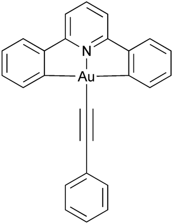 | ||
| Chart 1 Parent phosphorescent gold(III) chromophore as reported by Yam et al.20 | ||
Using this observation as a base, numerous analogues have been prepared21–46 and solution PLQY values for triplet emission in acetylide derivatives of up to 61% have been reported.26 More recently values of up to 94% have been recorded based on singlet emission by TADF from gold(III) complexes with tetradentate ligands,47,48 while in solution-processed devices, external quantum efficiencies (EQE) of 15–16% have been achieved.28,49 More recently, Li et al. considered design strategies that address both thermal stability and photophysical efficiency of complexes of this general type. Based on isomeric CCN pincer ligands with carbazole donor ligands, they have reported EQE values of up to 11.9% for devices constructed using solution processing, which rise to 21.6% if vacuum deposition is employed. In both cases, the devices show long operational half-lives.50
Given the increasing interest in the gold(III) system just described and our previous experience with phosphorescent liquid crystals, we have undertaken a study that encompasses the design and synthesis of emissive liquid-crystalline complexes of gold(III) as well as an evaluation of their photophysical response and their performance in solution-processed OLEDs. To the best of our knowledge, the vast majority of known gold-based liquid-crystalline materials51,52 are linear and based on Au(I) with a C–Au–X or C–Au–C skeleton. As such, the materials reported here represent a new family of metallomesogens and present an opportunity to develop an understanding of the relationship between the molecular structure of the complexes and both liquid crystal and emission properties. In this contribution, we now report a series of gold(III) complexes which, by virtue of modified pincer and acetylide ligands, exhibit liquid crystalline properties. The effects of different ligand substitution patterns on the photophysical properties of the complexes are described, notably the raising in energy of the pincer-based HOMO on incorporation of alkoxy groups. Device data demonstrate that the complexes exhibit an EQE of up to 7.14%.
Synthesis
The target compounds have two principal components, the tridentate, pincer-like CNC ‘backbone’ and the monodentate acetylide ligand. The pincer proligands were readily prepared by coupling a mono- or di-methoxyphenylboronic acid with 2,6-dibromopyridine using a Suzuki–Miyaura protocol (Scheme 1, step (i)). The bis(methoxyphenyl)pyridine and bis(dimethoxyphenyl)pyridine products, 1, were demethylated using molten pyridinium chloride to give 2, after which a Williamson ether reaction of the phenolic or catecholic product with 1-bromododecane furnished the desired ligands. Smooth, high-yielding auration of such ligands is only possible when they are first reacted with mercury(II) acetate to give a cyclomercurated intermediate 4, from which transmetallation with tetrachloroaurate(III) yielded the chlorogold(III)–CNC complex, with a yield over two steps of 26% for 5 and 13% for 14.53 The required mono-, di- or -tri-alkoxyphenyl-substituted alkynes were prepared from the corresponding benzaldehyde using a Corey–Fuchs protocol (Scheme 2). In the case of 4-alkoxyphenylbenzaldehyde and 3,4-dialkoxybenzaldehyde, the precursors were the simple hydroxy analogues, whereas 3,4,5-trialkoxyphenylbenzaldehyde was obtained starting from methyl 3,4,5-trihydroxybenzoate wherein the ester was reduced to the benzyl alcohol before being re-oxidised to the aldehyde. The gold acetylides were prepared by the copper-mediated metathesis of the chloro ligand of complexes 5 and 14 with the alkyne (Scheme 1, step (vi)). Using this approach, a family of 26 new complexes (including two further complexes incorporating 4-ethynylpyridine as the monodentate ligand) was obtained.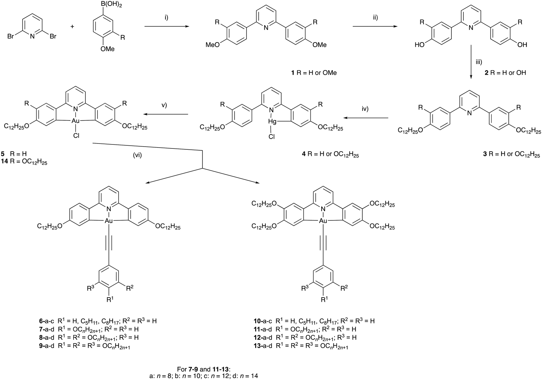 | ||
Scheme 1 Synthetic route to the target complexes: (i) [Pd3(OAc)6]/K3PO4/HOCH2CH2OH; (ii) pyH+Cl−/Δ; (iii) C12H25Br/K2CO3/DMF; (iv) (a) Hg(OAc)2/EtOH, (b) LiCl/MeOH; (v) K[AuCl4]/MeCN/CHCl3/Δ; (vi) Ar–C![[triple bond, length as m-dash]](https://www.rsc.org/images/entities/char_e002.gif) C–H/CuI/Et3N/CH2Cl2. C–H/CuI/Et3N/CH2Cl2. | ||
 | ||
| Scheme 2 Synthetic route to the phenylacetylenes: (i) CBr4/PPh3/CH2Cl2; (ii) (a) EtMgBr in THF, (b) NH4Cl. | ||
X-ray single crystal structures of 5, 6a and 6b
For complexes 5, 6a and 6b it was possible to obtain crystals of sufficient quality to allow structure determination by X-ray methods and the crystallographic data are compiled in Table S1 (ESI†). A brief description of the structure of 5 is given in the ESI,† while those of 6a and 6b are described here. In both complexes (Chart 2), the gold sits in an approximately square planar environment where, for example in 6a, the C–Au–C angles within the pincer ligand are 162.7(3)° and the N–Au–C angles are about 177.6(3)°. There is also a small bend in the acetylenic bond such that the Au–C–C angle is 173.2(6)°, the reason for which appears evident when packing is taken into consideration. As shown in Chart 2c there is an interdigitation of the alkyl chains which apparently enables the space to one side of the phenylacetylide to be filled by a second molecule of complex (Chart 2c).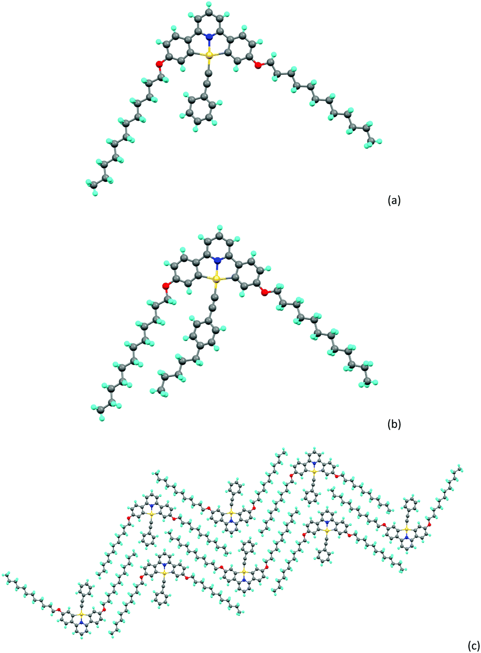 | ||
| Chart 2 (a) Molecular structure of complex 6a, (b) molecular structure of complex 6b, (c) packing of complex 6a. | ||
Solution studies by NMR spectroscopy
Luminescent gold-acetylide prone to aggregation (e.g. through gel formation) have been studied in solution by NMR spectroscopy at various concentrations, predominantly by Yam and co-workers, with many of these studies being of complexes bearing a 3,4,5-trialkoxyphenylacetylide co-ligand.42–44 Similar effects have been observed by Suleymanova et al. for a cyclometallated platinum(II) complex studied by both 1H and 195Pt NMR spectroscopy.54 In order to quantify this effect to determine if the aggregation might influence the photophysical properties of these complexes, rigorous, concentration-dependent studies of 13a were undertaken by 1H NMR and electronic spectroscopies. The labelling of the hydrogen atoms in this complex is shown in Fig. 1.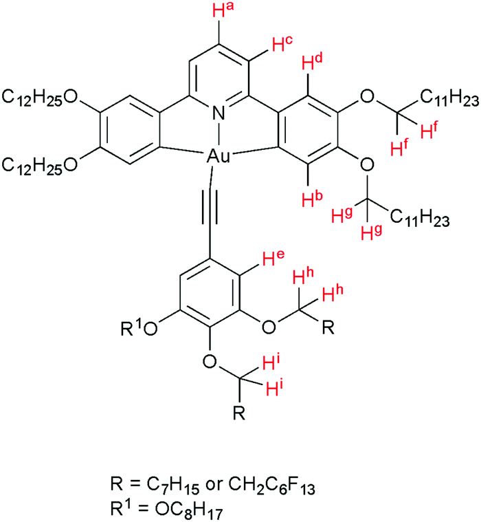 | ||
| Fig. 1 Structure of 13a, showing the labelling system for the H-atoms. | ||
The 1H NMR spectra for 13a recorded in CD2Cl2 at a range of concentrations are shown in Fig. 2 and 3. A downfield shift is observed for the aromatic protons on the pincer ligand (Ha, Hb, Hc and Hd) with decreasing concentration. The absolute change in the chemical shift is small, with Δδ approximately 0.07–0.06 ppm on increasing the concentration from 5.0 × 10⁻⁵ mmol to 1.4 × 10⁻² mmol; nevertheless, the trend over this concentration range is clear (Fig. 2). A similar trend is also observed in the resonances for the O–CH2 protons of the alkyl chains on the cyclometallating ring, Hf and Hg (Fig. 3), although the shifts were smaller with Δδ between 0.02 and 0.04 ppm.
 | ||
| Fig. 2 1H NMR spectra of 13a at increasing concentration in CD2Cl2, showing the downfield shift of the aromatic protons on the pincer ligand. | ||
 | ||
| Fig. 3 1H NMR spectra of 13a at increasing concentrations in CD2Cl2, showing the change in the chemical shift of the O–CH2 hydrogen atoms of the alkyl chains on both ring systems. | ||
These data are consistent with a ‘back-to-back’ self-assembly in solution where there is overlap of the rigid aromatic cores of the complex, resulting in a shielding of the protons of the C^N^C ligand, and where the phenylalkynyl moiety is free of associations (Fig. 4). Similar self-association has been postulated previously in a number of systems.20,55
 | ||
| Fig. 4 Proposed aggregate of 13a in concentrated solution showing a ‘back-to-back’ dimer formed through interfacial interactions. Relative distances are exaggerated for clarity. | ||
The resonances for the acetylide ligand showed only a very small and opposite shift (Hh and Hi) or no concentration dependence (He). This would appear to indicate that any intermolecular process involving this region of the complex is different from that mediated by the C^N^C ligands.
Consideration of the data in Fig. 2 and 3 shows clearly that the change in chemical shift ceases as the concentration decreases below approximately 1 × 10⁻⁴ M. Electronic spectroscopy below this concentration regime (see below) shows no change in the absorption profile, positions of maxima, or molar extinction coefficients for any of the observed transitions, nor the appearance of any new absorption bands. This is consistent with the lack of change in the 1H NMR spectra and therefore under these dilute conditions the extent of aggregation is minimal.
Liquid-crystalline behaviour of the new complexes
The liquid crystal properties of the new complexes were studied using polarised optical microscopy, differential scanning calorimetry (DSC) and small-angle X-ray scattering (SAXS). They are considered first as two groups – with two (5 to 9) and then with four (10 to 13) terminal chains on the pincer ligand.Complexes with two terminal chains on the pincer ligand (5 to 9)
The transition temperatures for complexes 5 to 9 are given in Table 1, while the SAXS data are collected in Table S2 (ESI†). Complex 5 shows an ordered lamellar phase between 91.9 and 159.8 °C as identified by SAXS data (d-spacing of 30.7 Å, Fig. S3a, ESI†), with microscopy showing a texture lacking in identifiable defects (Fig. S3b, ESI†). A broad and weak reflection at 8.9 Å was assigned tentatively as a gold–gold separation, but the presence of several other wide-angle reflections most likely indicates a degree of order in the phase consistent with crystalline order, a conclusion supported by the large clearing enthalpy of 26.8 kJ mol−1.| Complex | Transitionc | T (°C) | ΔH (kJ mol−1) |
|---|---|---|---|
| a Observed on second heating cycle. b Overlapping Cr–Cr and Cr–Colh peaks. c Cr = crystal; Iso = isotropic fluid; Lam = lamellar; Colh – hexagonal columnar phase. | |||
| 5 | Cr–Lam | 91.9 | 37.4 |
| Lam–Iso | 159.8 | 28.6 | |
| 6a | Cr–Iso | 71.2 | 57.2 |
| 6b | Cr–Cr′ | 45.3 | 1.9 |
| Cr′–Cr′′ | 53.3 | 12.0 | |
| Cr′′–Iso | 68.2 | 8.2 | |
| 6c | Cr–Colh | 57.0 | 16.3 |
| Colh–Iso | 69.0 | 1.7 | |
| 7a | Cr–Iso | 101.8 | 38.2 |
| (Iso–Colh) | (90.6) | (3.6) | |
| 7b | Cr–Iso | 102.5 | 32.2 |
| 7c | Cr–Iso | 95.9 | 34.8 |
| 7d | Cr–Iso | 101.8 | 34.4 |
| 8a | Cr–Cr | 67.2 | 12.3 |
| Cr–Colh | 75.7 | 45.3 | |
| Colh–I | 103.8 | 5.3 | |
| 8b | Cr–Cr | 71.8 | 7.9 |
| Cr–Colh1 | 77.9 | 39.1 | |
| Colh1–Iso | 104.9 | 5.8 | |
| (Colh2–Colh1) | (50.6) | (1.2) | |
| 8c | Cr–Colhb | 77.5 | 40.0 |
| Colh–Iso | 101.8 | 3.9 | |
| 8d | Cr–Cr′ | 74.9 | 21.3 |
| Cr′–Colh | 82.8 | 7.2 | |
| Colh–I | 100.1 | 3.9 | |
| 9a | Cr–Colr | 55.0 | 3.9 |
| Colr–I | 80.7 | 22.9 | |
| 9b | Cr–Cr | 64.6 | 1.3 |
| Cr–Colr | 79.8 | 13.9 | |
| Colr–Colh | 88.3a | 5.7a | |
| Colh–I | 96.7a | 2.9a | |
| 9c | Cr–Cr | 57.8 | 0.8 |
| Cr–Colr | 78.1 | 16.9 | |
| Colr–Colh | 95.7 | 32.7 | |
| Colh–Iso | 102.1 | — | |
| 9d | Cr–Cr | 52.7 | 2.2 |
| Cr–Colh | 77.9 | 53.4 | |
| Colh–Iso | 88.0 | 3.0 | |
| (Colh–Colr) | (77.8) | (2.9) | |
Of complexes 6 and 7, only 6c and 7a show a mesophase (Colh), which is enantiotropic in the former and monotropic in the latter, although interestingly it is more stable in 7a than in 6c. However, when the coverage of the 2D surface of the complex increases with two (8) or three (9) terminal chains on the phenylacetylide, then all of the complexes show enantiotropic Colh and/or Colr phases. In general, the phases of these complexes did not give rise to good optical textures and in several cases the SAXS data did not show the higher-order reflections that would confirm the identity (Fig. S4, ESI†). In these cases, it was necessary to identify the phase through miscibility with a complex whose mesophases were characterised unequivocally by SAXS.
Complexes of 8, which have a 3,4-dialkoxyphenylethynyl co-ligand, all show columnar hexagonal phases (d10 and d11 reflections seen in the SAXS data) with the melting and clearing points varying little with terminal chain length to give mesophase ranges of between 18 and ≈30 °C. Interestingly, complex 8b showed a more complex mesomorphism with up to three Colh phases being observed, two of which appear monotropic. For complexes 9, the first three in the series (9a–9c) showed a Colr phase on heating, above which there was a Colh phase for 9b and 9c; complex 9d showed a Colh phase with a Colr phase appearing monotropically. In all cases the nature of the phase was confirmed by SAXS data. Complexes 9b–9d showed some solid-state polymorphism and all melted to the first mesophase at around 78 °C, whereas in 9a melting occurred at the much lower temperature of 55 °C. Clearing points increased significantly from 9a to 9c (81 to 102 °C) and then dropped in 9d (88 °C). The behaviour of these complexes is displayed in Fig. 5.
 | ||
| Fig. 5 Transition temperatures and phases for 6 to 8; the melting point of 7a is shown as a black bar (phase is monotropic). | ||
Complexes with four terminal chains on the pincer ligand (10 to 13)
In contrast to complexes 5 to 9, the phase behaviour of complexes 10 to 13 with four chains on the cyclometallating ligand is rather uniform, inasmuch as they all show a columnar hexagonal phase. Data on transition temperatures are found in Table 2 and are plotted in Fig. 6. The phases were characterised by SAXS data, which showed characteristic d10, d11 and, in most cases, d20 reflections (Fig. 7a and Table S3, ESI†) and by their characteristic optical textures (Fig. 7b).| Complex | Transition | T (°C) | ΔH (kJ mol−1) |
|---|---|---|---|
| a Not observed by DSC. | |||
| 10a | Cr–Colh | 87.7 | 57.7 |
| Colh–Ia | 105.9 | — | |
| 10b | Cr–Colh | 74.0 | 28.8 |
| Colh–Ia | 179.8 | — | |
| 10c | Cr–Colh | 71.4 | 62.8 |
| Colh–Ia | 185.0 | — | |
| 11a | Cr–Colh | 83.9 | 58.7 |
| Colh–Ia | 172.1 | — | |
| 11b | Cr–Colh | 77.4 | 75.6 |
| Colh–Ia | 163.2 | — | |
| 11c | Cr–Colh | 77.3 | 91.2 |
| Colh–Ia | 147.8 | — | |
| 11d | Cr–Colh | 72.2 | 68.0 |
| Colh–Ia | 189.4 | — | |
| 12a | Cr–Colh | 83.0 | 85.3 |
| Colh–Ia | 191.2 | — | |
| 12b | Cr–Colh | 81.0 | 82.1 |
| Colh–Ia | 179.3 | — | |
| 12c | Cr–Colh | 77.0 | 73.3 |
| Colh–Ia | 170.7 | — | |
| 12d | Cr–Colh | 80.0 | 103.2 |
| Colh–Ia | 154.5 | — | |
| 13a | Cr–Cr | 44.2 | 50.8 |
| Cr–Colh | 53.4 | 97.8 | |
| Colh–Ia | 187.2 | — | |
| 13b | Cr–Colh | 58.9 | 62.1 |
| Colh–I | 195.1 | 4.3 | |
| 13c | Cr–Colh | 71.2 | 75.1 |
| Colh–I | 183.9 | 5.9 | |
| (Colh–Lam) | (39.4) | (101.2) | |
| 13d | Cr–Colh | 89.0 | 118.9 |
| Colh–I | 166.0 | 2.8 | |
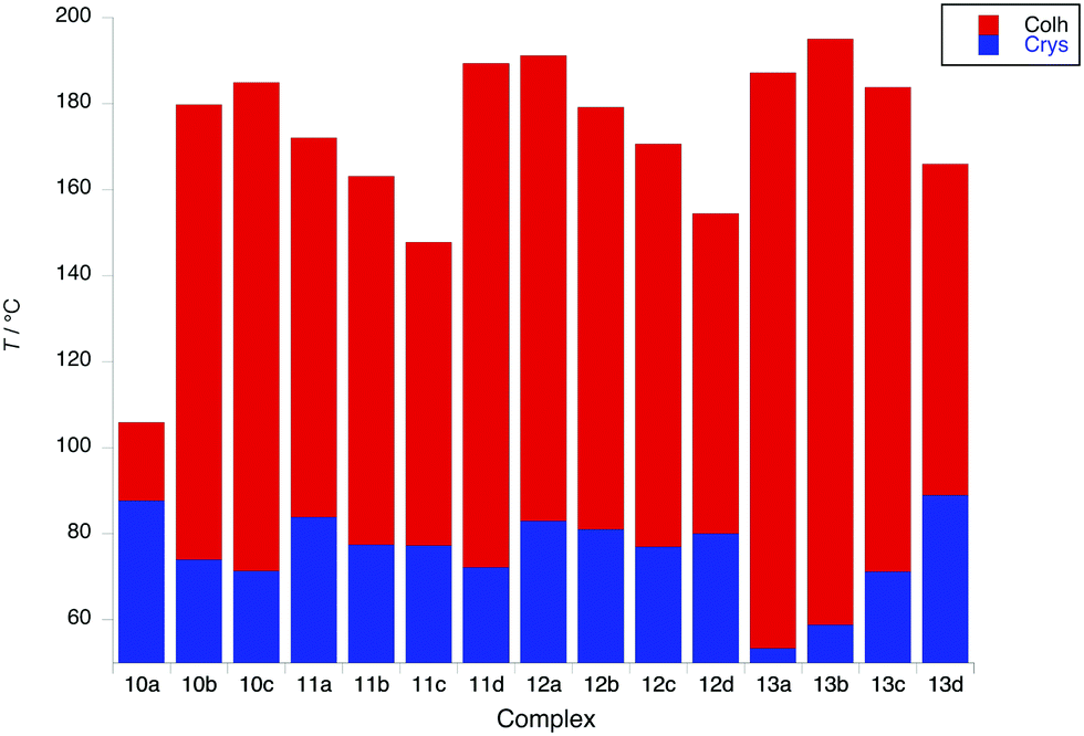 | ||
| Fig. 6 Transition temperatures and phases for complexes 10 to 13. | ||
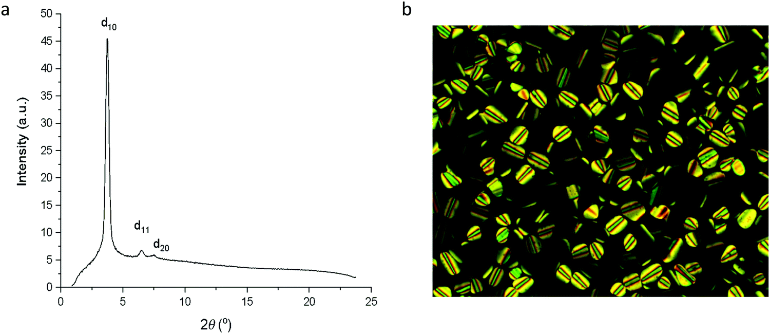 | ||
| Fig. 7 (a) SAXS pattern for 10b at 107 °C in the Colh phase; (b) photomicrograph of 10b on cooling at 167 °C in the Colh phase. | ||
The first point of note is that the mesophases are significantly more stable in complexes 10 to 13 with clearing points up to 100 °C higher than in complexes 5 to 9 (Fig. S5, ESI†). This is understood by the observation that the periphery of the complexes is better covered by flexible chains (four chains on the pincer ligand) which will in turn give a greater ‘cohesion’ of the complexes within the columns, so increasing mesophase stability. This explains the depressed phase stability of 10a, as in all of the other complexes, the V-like area defined by the pincer ligand and the chains in the 4-positions is filled giving a more disk-like unit that can pack effectively. In general within complexes 11, 12 and 13, there is a decrease in mesophase stability as the chains on the phenylacetylide group increase in length, with a surprisingly enhanced stability observed for 11d. Melting points in complexes 11 and 12 vary little, although in 13 they increase monotonically with the increasing chain length. Interestingly, 12c shows a fairly strongly monotropic phase, identified as lamellar, consistent with the observation of a single reflection in the SAXS data.
Considering the structural data obtained from SAXS, some differences between the two families of complexes are evident. Thus, the hexagonal lattice parameter, a, which represents the intercolumnar distance, is consistently greater for complexes 8 and 9 than for four-chain analogues 12 and 13. Thus, for 8 and 9, a varies between 36 Å (n = 8) and ca. 38.5 Å (n = 14) whereas for 12 that range is 29.4 to 31.6 Å and for 13 it is 31 to 33 Å. Note that in all cases there is little dependence on the terminal chain length. To account for this difference, it is proposed that complexes 8 and 9 are more akin to a formal half-disk and so would be likely to associate in a back-to-back fashion similar to the arrangement shown in Fig. 4. This would help fill space better and is a motif that has commonly been proposed for half-disk materials previously.56–58 However, for 12 and 13, the extra two chains on the pincer make the complex more intrinsically disk-like so that the repeat unit is effectively a single complex, which is a more compact arrangement, consistent with the structural data. Thus, the solution behaviour does not predict the organisation in the mesophase.
An interesting observation was that with the exception of 13b, 13c and 13d, none of the complexes 10–13 showed a clearing event by differential scanning calorimetry (DSC), even though by microscopy the transition was sharp and readily observable. Where a transition enthalpy could be measured it was small, particularly for columnar phases, with values of 4.3, 5.9 and 2.8 kJ mol−1 being found for 13b, 13c and 13d, respectively, comparable to the data found in complexes 6–9 (3.9 to 5.8 kJ mol−1). These data suggest that the columnar phase is quite disordered. Interestingly, SAXS data recorded in the isotropic phase (Fig. 8) showed a broad reflection at around 3.5° 2θ, which corresponds to a distance of ca. 25 Å. Taken together, these observations suggest that at the clearing point there is a second-order melting of the hexagonal lattice to give a formally isotropic phase in which the columns persist but lose their long-range correlation. This is analogous to the situation found at the clearing points of, for example, chiral nematic, cubic and TGB phases as described by Goodby et al.59 where a very similar situation of lattice melting is described. This topic has more recently been re-visited.60
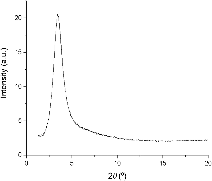 | ||
| Fig. 8 SAXS pattern of 12b in the isotropic liquid showing a broad reflection in the small-angle region. | ||
Photophysical measurements
Absorption spectra
The UV-vis absorption spectra of the complexes were recorded in CH2Cl2 at room temperature; absorption maxima and corresponding extinction coefficients are summarised in Table 3. The spectra fall into two categories, those with two chains on the pincer ligand (6 to 9) and those with four (10 to 13). Within these two groups, the spectral profiles are effectively independent of the identity of the arylacetylide ligand.| Complex | Absorption λmax/nm (ε/M−1 cm−1) | Emission λmax/nm |
φ
lum × 102![[thin space (1/6-em)]](https://www.rsc.org/images/entities/char_2009.gif) b b |
τ/nsc degassed [aerated] | k r /103 s−1 | ∑knrd/103 s−1 | k Q(O2)e/109 M−1 s−1 | Emission 77 Kf | |
|---|---|---|---|---|---|---|---|---|---|
| λ max/nm | τ/μs | ||||||||
|
a In degassed CH2Cl2 at 295 ± 3 K, except where indicated otherwise.
b Quantum yields measured relative to [Ru(bipy)3]Cl2(aq).
c In degassed solution; values in air-equilibrated solution are given in parenthesis.
d Radiative kr and non-radiative ∑knr rate constants estimated from quantum yield and lifetime: kr = ϕ/τ, knr = (1 − ϕ)/τ.
e Bimolecular Stern–Volmer constant for quenching by molecular oxygen.
f In diethyl ether–isopentane–ethanol (2:2:1 v/v).
g Poor fit to mono-exponential kinetics.
|
|||||||||
| 6a | 260 (57600), 272 (55200), 310 (22100), 325 (22800), 411 (8300), 430 (8100) |
502, 534 | 1.6 | 13000 [380] |
1.2 | 76 | 1.2 | 507, 544 | 270 |
| 6c | 263 (61900), 272 (59000), 313 (24600), 324 (25300), 412 (8720), 430 (8870) |
501, 533 | 3.4 | 9200 [470] | 3.7 | 100 | 0.97 | 515, 548 | 410/160g (2:1) |
| 7a | 264 (69000), 272 (68900), 314 (26000), 326 (27800), 411 (6890), 431 (7120) |
501, 532 | 3.6 | 7300 [460] | 4.9 | 130 | 0.93 | 511, 548, 691sh | 290 |
| 8a | 266 (67600), 272 (70400), 312 (25700), 325 (27800), 410 (9120), 431 (9040) |
501, 533 | 2.3 | 7000 [410] | 3.3 | 140 | 1.0 | 511, 552, 594sh | 430/160g (2:1) |
| 9a | 266sh (66400), 272 (69600), 312 (22500), 325 (25500), 410 (6800), 431 (6220) |
502, 534 | 2.7 | 8400 [400] | 3.3 | 120 | 1.1 | 525, 556 | 300/120g (2:1) |
| 10a | 259 (61700), 282 (44900), 300sh (20400), 340 (17600), 445 (4880) |
553, 581sh | 36 | 150000 [350] |
2.4 | 4.3 | 1.3 | 565, 611 | 230 |
| 10c | 259 (62800), 279sh (44000), 340 (20000), 440 (2590) |
551, 579 | 19 | 60000 [390] |
3.1 | 14 | 1.2 | 565, 610, 661sh | 240 |
| 11a | 260 (57200), 282sh (43200), 341 (22000), 444 (3530) |
554, 582 | 34 | 100000 [390] |
3.4 | 6.6 | 1.2 | 565, 612, 661sh | 220 |
| 12a | 262 (65100), 297sh (38600), 342 (23100), 448 (5080) |
552, 581 | 34 | 120000 [390] |
2.9 | 5.5 | 1.2 | 559, 600, 649 | 260/120g (4:1) |
| 13a | 262 (59500), 300sh (36400), 341 (23000), 448 (3560) |
552, 579 | 20 | 77000 [390] |
2.6 | 10 | 1.2 | 562, 603, 659 | 200 |
The effect of the different number of chains on the pincer ligand is exemplified in Fig. 9, which shows the spectra of 6c and 10c as representative examples with two and four chains, respectively. In 6c, there are three main absorptions, each apparently comprising of a pair of closely separated bands. The lowest-energy absorption comprises a band centered at 430 nm (ε = 8870 M−1 cm−1) and a second transition at 412 nm of a similar intensity. There are no such bands in the visible region for the proligands, and these bands can be attributed to charge-transfer transitions arising from the introduction of the metal. (Insight into the orbital parentage of transitions giving rise to them is provided by TD-DFT calculations, which are discussed further below: they show that the transitions can be considered to be predominantly LLCT in nature owing to a low contribution of the metal.) At higher energy in the UV region, there are two further, more intense pairs: 324 and 313 nm (ε = 25300 and 24600 M−1 cm−1), and 272 and 263 nm (ε = 59000 and 61900 M−1 cm−1). The energy separation within the pairs is around 1100–1300 cm−1, a value consistent with the C![[double bond, length as m-dash]](https://www.rsc.org/images/entities/char_e001.gif) N and CC vibrational stretching frequencies of the diphenylpyridine ligand (i.e. excitation to the first and second vibrational levels of the excited states being resolved), and in line with previous studies.20,23,41,53,61
N and CC vibrational stretching frequencies of the diphenylpyridine ligand (i.e. excitation to the first and second vibrational levels of the excited states being resolved), and in line with previous studies.20,23,41,53,61
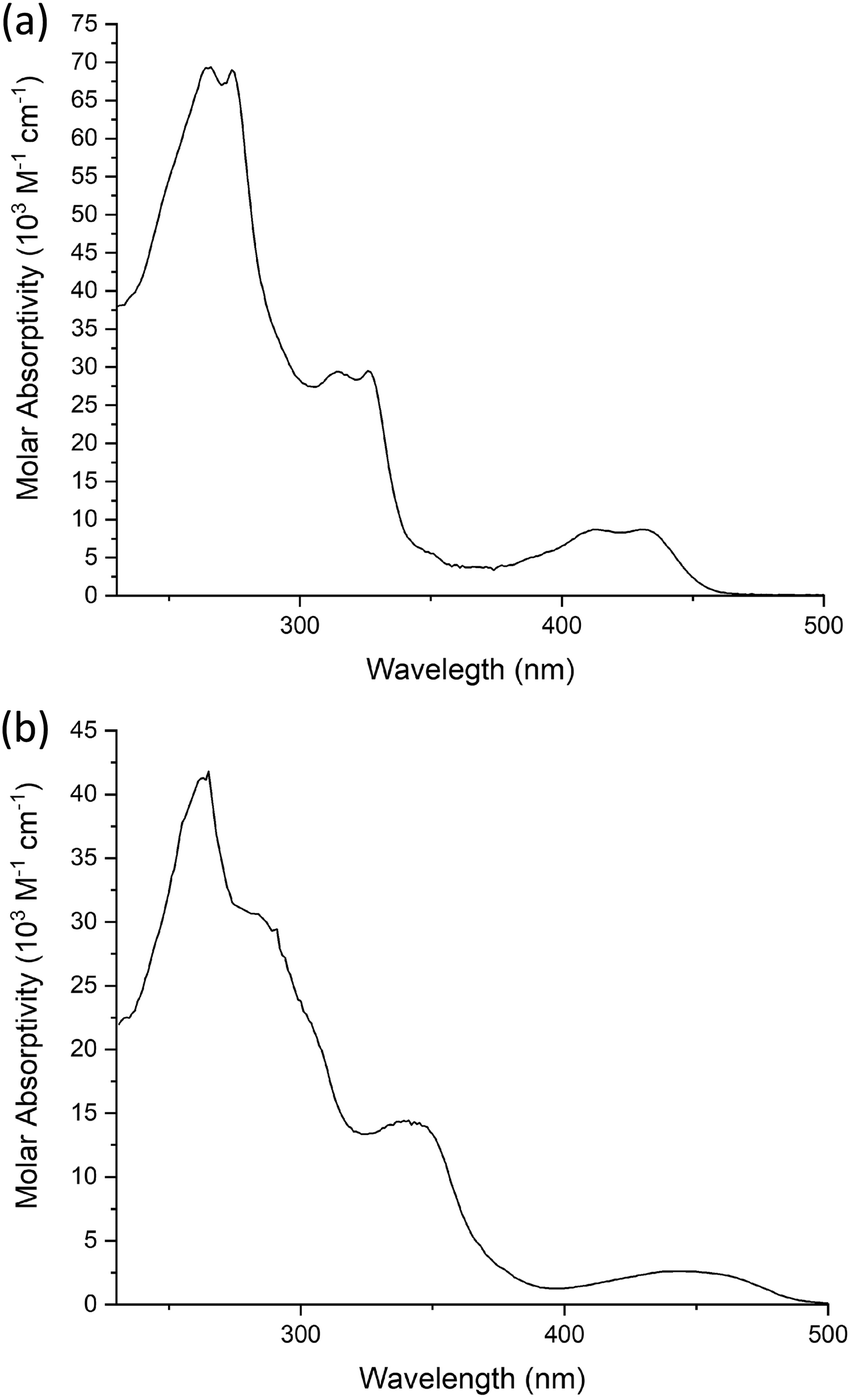 | ||
| Fig. 9 UV-visible absorption spectra of (a) 6c and (b) 10c in CH2Cl2 at room temperature. | ||
The spectra of the complexes with four chains on the pincer ligand are subtly different in that the lowest-energy band is red-shifted, its molar absorptivity is reduced significantly and the vibrational structure in all the bands is lost, perhaps indicative of more effective coupling of the excited state with lower-energy vibrations. For 10c as an example (Fig. 9), the lowest energy band is red-shifted to 440 nm (ε = 2590 M−1 cm−1) with other, more intense absorptions again at shorter wavelengths 340 (ε = 20000 M−1 cm−1), 279sh (ε = 44000 M−1 cm−1) and 259 (ε = 62800 M−1 cm−1) nm.
Photoluminescence
The gold(III) precursor complexes 5 and 14 that contain chloride as the monodentate ligand showed no detectable luminescence at room temperature. This lack of emission is consistent with literature precedent, which attributes it to deactivation through low-lying d–d excited states.53 In contrast, all of the acetylide derivatives 6 to 13 were phosphorescent in dichloromethane solution at room temperature, appearing green (6–9) or yellow (10–13). The promotion of the emission through the replacement of a chloride ligand by an acetylide is consistent with the d–d states being raised in energy by the strongly σ-donating nature of the acetylide, as also found for many platinum(II) complexes such as those of the form [Pt(tpy)X]+. Table 3 lists photophysical data for only a single chain length of each complex type (i.e. the a series where n = 8, substituent(s) = –OC8H17) as there was no discernible effect of changing the alkoxy chain length on the emission properties. Spectra and luminescence lifetimes have also been recorded at 77 K in a transparent glass of composition diethyl ether/isopentane/ethanol (2:2:1 v/v; referred to as EPA).
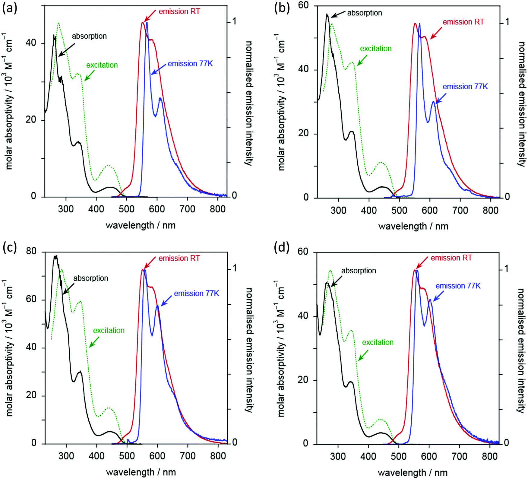
Complexes 6 to 9 display essentially identical emission spectra to one another in deoxygenated CH2Cl2 solution at 295 K (Fig. 10 and Table 3). The spectra show clear vibrational structure, with the 0,0 component being the most intense, at 501 ± 1 nm, and with a vibrational progression of approximately 1200 cm−1. Given that this band is independent of substituents in the alkyne, and with reference to the computational work (below) and literature precedent, the emission is assigned as arising from a metal-perturbed 3[π → π*] intraligand transition based on the diphenylpyridine ligand.20–22,31,41,62 The temporal decay of the luminescence fits well to monoexponential kinetics, and the lifetimes are around 8 μs (Table 3). The emission is strongly quenched in air-equilibrated solution, and lifetimes are reduced under these conditions to around 400 ns. These observations are quite typical of many AuIII and PtII complexes that emit from triplet excited states. The quantum yields are around 3%, significantly higher than the related unsubstituted complexes reported by Wong et al.,41 and are comparable to those of more recently designed gold(III) complexes.20,23,28,34,36,37,41,43 There was no significant change in the emission spectral profiles, nor any significant decrease in the lifetimes, on increasing the concentration by an order of magnitude (to around 2 × 10⁻⁴ M). Any aggregation or intermolecular interactions in the ground or excited state are thus apparently minimal over this range. Only weak and poorly defined emission was detectable in the (neat) solid state, as commonly found for many planar aromatic fluorophores, and also for triplet-emitting metal complexes, where microsecond lifetimes facilitate intermolecular excited state annihilation processes.
 | ||
| Fig. 10 Absorption spectra (black lines), excitation (dashed green lines), and emission spectra (red lines) for the two-chain complexes (a) 6c, (b) 7a, (c) 8a and (d) 9a in CH2Cl2 at 295 K. The emission spectra at 77 K in EPA are also shown (blue lines). | ||
Although the emission properties are similar for all five complexes (6c and 6a–9a), close inspection of the data in Table 3 suggests a subtle difference for complex 6a, which lacks substituents in the alkynylbenzene unit. It has a rather longer lifetime but a lower quantum yield than 6c or 7a–9a. Assuming that the emissive state is formed with unit efficiency, the radiative and non-radiative rate constants, kr and ∑knr, can be estimated from the quantum yields and lifetimes (Table 3). These data suggest that kr is increased by a factor of around 2–4 upon introduction of the substituents, whilst ∑knr is only modestly increased, leading overall to the superior quantum yields displayed by the substituted complexes.
At 77 K (Fig. 10 and Table 3), the vibrational structure becomes more pronounced, and there is a small but definitive red shift. This is unexpected as most metal complexes tend to exhibit a hypsochromic shift on cooling due to the rigidochromic effect, although that is typically most pronounced for complexes that emit from MLCT states.63 One possible explanation is the formation of small clusters under low-temperature conditions, through metal–metal interactions: such entropically disfavoured interactions will tend to stabilise the emissive state and thus lead to an apparent red-shift. The temporal decay of emission at 77 K shows rather poor fits to mono-exponential kinetics; this observation would also be consistent with formation of cluster-like species through intermolecular interactions. However, it might also reflect emission from non-equilibrated, close-lying excited states. Nevertheless, the long lifetimes of several hundred microseconds for the major components suggest that the emission emanates from states that are probably quite heavily localised on the ligand, with only a relatively modest contribution from the metal.
For the five complexes that incorporate four chains on the diphenylpyridine ligand (10c, 10a–13a), the emission spectra are similar to one another (Fig. 11 and Table 3). Their emission is red-shifted compared to the two-chain analogues, with λmax(0,0) increased to 553 ± 2 nm. Vibrational structure is again discernible, though a little less well-resolved than in the two-chain complexes, as was also noted in the absorption spectra. The most dramatic difference between the two series of complexes is, however, the much higher luminescence quantum yields – an order of magnitude greater, reaching as much as 36%. These values are amongst the highest values recorded in the literature for phosphorescent emitters of this type (i.e. [Au(CNC)-acetylide]). Indeed, the vast majority of such complexes of this general design show PLQY values <10%21,30,32,42,64,65 and, very often, <1%.20,23,28,34,36,37,41,43
 | ||
| Fig. 11 Absorption spectra (black lines), excitation (dashed green lines), and emission spectra (red lines) for the four-chain complexes (a) 10c, (b) 11a, (c) 12a, and (d) 13a, in CH2Cl2 at 295 K. The emission spectra at 77 K in EPA are also shown (blue lines). | ||
The increase in quantum yields is accompanied by longer lifetimes. Indeed, estimation of the kr and ∑knr values (Table 3) reveals that the enhanced performance is due to a reduction in the non-radiative decay rate by an order of magnitude compared to the two-chain series. The kr values, in contrast, are essentially the same for both series. The beneficial effect of inclusion of two further electron-donating alkoxy chains on the pincer ligand, in reducing non-radiative decay processes, can be rationalised readily. As noted, their inclusion decreases the energy of the emissive excited state by around 2000 cm−1 based on the λmax(0,0) values. Thus, the activation energy to populate the deactivating d–d states will increase by approximately this magnitude, essentially cutting off this pathway of deactivation at room temperature and leading to the enhanced quantum yields. Amongst the five complexes, there are some small variations in φ and τ, with 11a, 12a and the unsubstituted 10a showing the highest values.
At 77 K in EPA glass, the vibrational structure becomes better resolved. Again, there is an unexpected, small but definite red shift in the spectra compared to those recorded in solution at 295 K. The emission decay at 77 K for these four-chain complexes fits monoexponential kinetics well (with the possible exception of 12a where a minor shorter component is apparent). The measured lifetimes under these conditions (Table 3) are similar to those of the two-chain series: at this temperature, non-radiative decay via higher-lying d–d states will evidently be ruled out even for the two-chain complexes.
Computational chemistry
Time-dependent density functional theory (TD-DFT) was employed to rationalise the nature of the absorption and emission spectra of the gold acetylide complexes. As the photophysical properties were essentially independent of alkyl chain length, and to aid with computational efficiency, these groups were substituted by either ethyl or methoxy units for the purpose of the calculations. The structures and numbering for these model complexes are shown in Chart 3. The geometries of the complexes were optimised at the BP86/SV(P) level and subsequent single-point energy and TD-DFT calculations were performed using the PBE0 functional with the def2-TZVPP basis set. The composition of the two lowest-energy electronic transitions for each complex are presented in Table 4 and compared to the experimental absorption spectra.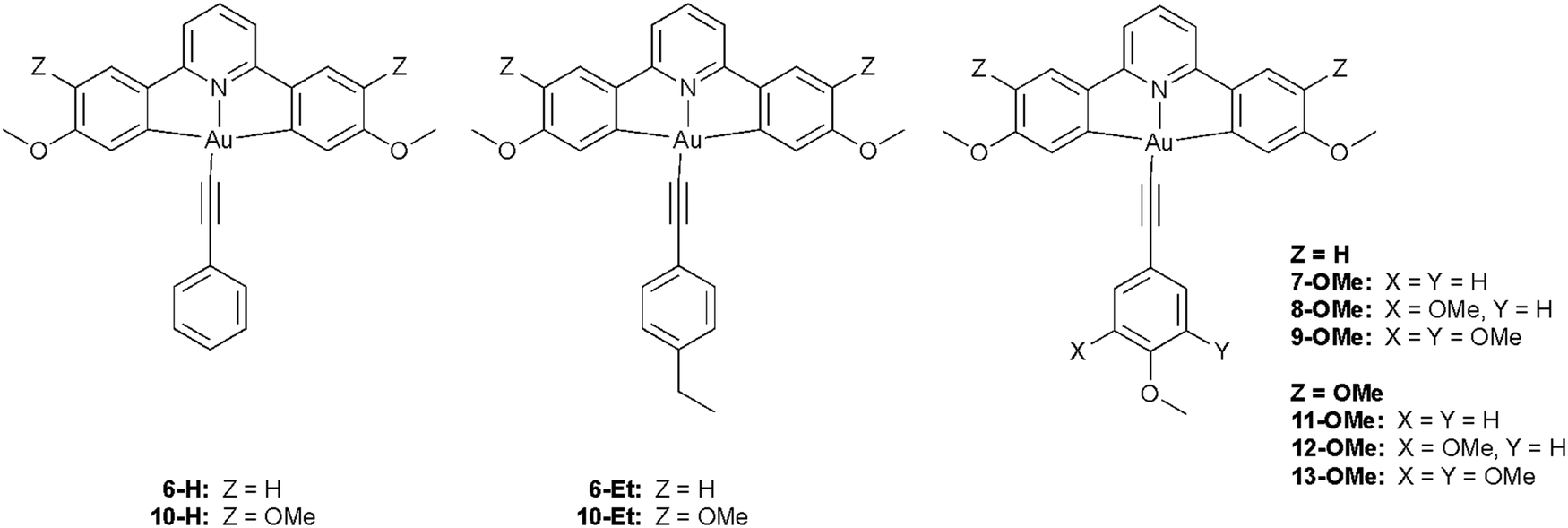 | ||
| Chart 3 Structures of model complexes with truncated alkoxy substituents used for calculations. | ||
| Complex | Calculated energy/103 cm−1 (λcalc|λexp)/nm | Oscillator strength | Transition (% coefficient) |
|---|---|---|---|
| a Whilst an approximation, the experimental energy of S1 is taken to be the lowest-energy absorption maximum. | |||
| 6-H | 24.7 (406|430) | 0.036 | HOMO → LUMO (94) |
| 25.1 (398|411) | 0.148 | HOMO−1 → LUMO (96) | |
| 6-Et | 24.0 (417|430) | 0.0476 | HOMO → LUMO (95) |
| 25.1 (398|412) | 0.148 | HOMO−1 → LUMO (95) | |
| 7-OMe | 22.7 (440|431) | 0.057 | HOMO → LUMO (96) |
| 25.1 (397|411) | 0.143 | HOMO−1 → LUMO (95) | |
| 8-OMe | 22.7 (441|431) | 0.056 | HOMO → LUMO (96) |
| 25.1 (398|410) | 0.142 | HOMO−1 → LUMO (95) | |
| 9-OMe | 22.5 (444|431) | 0.047 | HOMO → LUMO (96) |
| 25.1 (398|410) | 0.141 | HOMO−2 → LUMO (95) | |
| 10-H | 22.9 (438|445) | 0.0707 | HOMO−1 → LUMO (50) |
| HOMO → LUMO (48) | |||
| 24.2 (414|445) | 0.0352 | HOMO → LUMO (48) | |
| HOMO−1 → LUMO (46) | |||
| 10-Et | 22.5 (445|440) | 0.0545 | HOMO−1 → LUMO (93) |
| 23.9 (419|440) | 0.0404 | HOMO → LUMO (90) | |
| 11-OMe | 22.5 (445|444) | 0.0516 | HOMO−1 → LUMO (92) |
| 22.8 (439|444) | 0.0419 | HOMO → LUMO (91) | |
| 12-OMe | 22.5 (445|448) | 0.0520 | HOMO−1 → LUMO (95) |
| 22.9 (437|448) | 0.0548 | HOMO → LUMO (93) | |
| 13-OMe | 22.1 (452|448) | 0.00290 | HOMO → LUMO (93) |
| 22.5 (444|448) | 0.0533 | HOMO−1 → LUMO (94) | |
The resulting calculations of first singlet excited-state energies are a good match to the experimental data. For the two-chain complexes 6–9, two discrete, low-energy transitions corresponding to LUMO ← HOMO and LUMO ← HOMO−1 are predicted, separated by between 400 and 2600 cm−1. This might be represented in the observed splitting of the lowest energy band in the experimental spectra, although this observed structure could alternatively be due to excitation to a vibrationally excited level of S1.
Examination of the Kohn–Sham orbitals (Fig. 12) indicates that the HOMO−1 is based on the pincer ligand, whereas the HOMO is centered on the acetylide with some gold character. The LUMO is located primarily on the pyridyl ring of the pincer ligand. The energy of the LUMO ← HOMO transition is reduced by ca. 2000 cm−1 upon incorporation of donor groups into the acetylide ligand (7-OMe, 8-OMe and 9-OMe), which probably arises from an increase in the HOMO energy due to the influence of the donor groups (Fig. 13), and is consistent with the experimentally observed red-shift in the lowest-energy absorption band.
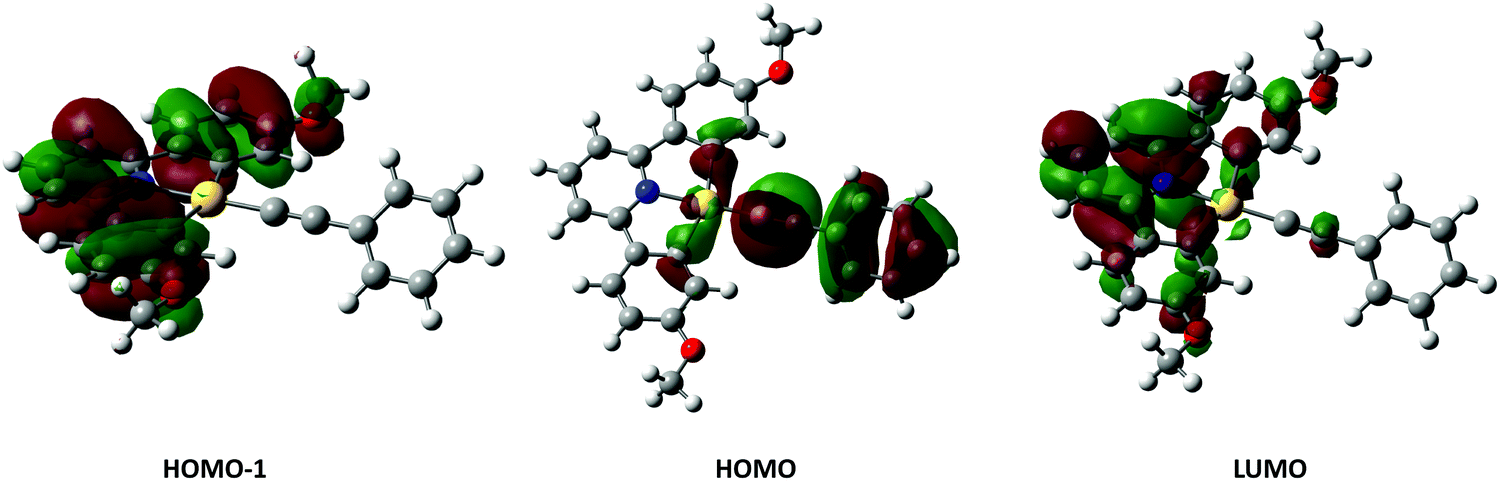 | ||
| Fig. 12 Calculated Kohn–Sham orbitals for complex 6H, isosurface set to the 0.005 level. | ||
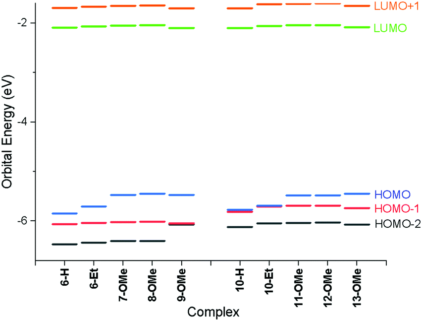 | ||
| Fig. 13 Energies of frontier molecular orbitals for all species calculated using the PBE0 functional with the def2-TZVPP basis set. | ||
In the case of the four-chain complexes 10–13, the additional alkoxy substituent to the backbone of the CNC ligand raises the energy of the HOMO−1 orbital (Fig. 13) resulting in the LUMO ← HOMO−1 transition being red shifted by between 2200 and 2700 cm−1 when compared to the two-chain analogues.
In addition to using TD-DFT to determine the singlet excitations, the geometries and energies of the triplet states of complexes 6-H and 10-H were calculated.‡ Subtraction of the energy of the corresponding ground state singlet complexes then allowed for the predicted energy of emission to be determined. For 6-H, this was 500 nm, which is in excellent agreement with the experimental value of 502 nm. Likewise, for 10-H, the calculated and experimental values are 548 and 553 nm respectively.
Device measurements
Cyclic voltammograms (CV) were recorded to explore the electrochemical properties of the gold complexes and to allow evaluation of the HOMO and LUMO levels. Data for complexes 6a and 10 are shown in Fig. S5 (ESI†) although experiments performed on other complexes in both series gave the same results; only quasi-reversible reduction potentials were detected for both complexes. Thus, complex 6a displays a reduction wave with an onset potential of −1.70 V, while complex 10a presents a reduction with an onset potential of −1.94 V (both vs. Fc/Fc+ = 0.0 V). No oxidation process was observed in the accessible window. The energy of the LUMO can be estimated directly from the reduction potential according to the method of Pan et al.,66 giving values of −2.72 and −2.48 V for 6a and 10a, respectively. In the absence of a measurable oxidation potential, an estimate of the HOMO energy can be obtained by subtracting the optical band gap (in turn estimated from the absorption onset) giving values of −5.41 and −4.96 V. The higher-lying HOMO of 10a is consistent with the calculations (Fig. 13) and the electron-donating nature of the additional alkoxy chains. These data informed the choice of materials for device fabrication (below).As noted in the introduction, one potential advantage of liquid-crystalline emitters is that the ordered mesophase offers the possibility for preferred conduction pathways in discotic materials,67 which could have a beneficial effect on device characteristics such as drive voltage. In order to test that assertion, the electron mobilities of three complexes (8d, 12d and 13d) were evaluated both in the pristine state and after annealing in the liquid-crystalline state. The measurements were made using the SCLC method (see ESI†) in a device structure of ITO/PEDOT (30 nm)/Au complex (ca. 100 nm)/MoO3 (8 nm)/Al (100 nm) and TIO/ZnO (30 nm)/Au complex (ca. 100 nm)/PFN-Br (5 nm)/Al (100 nm). The resulting current–voltage (IV) characteristics under pulse conditions are shown in Fig. 14 and the mobilities are found as Table 5.
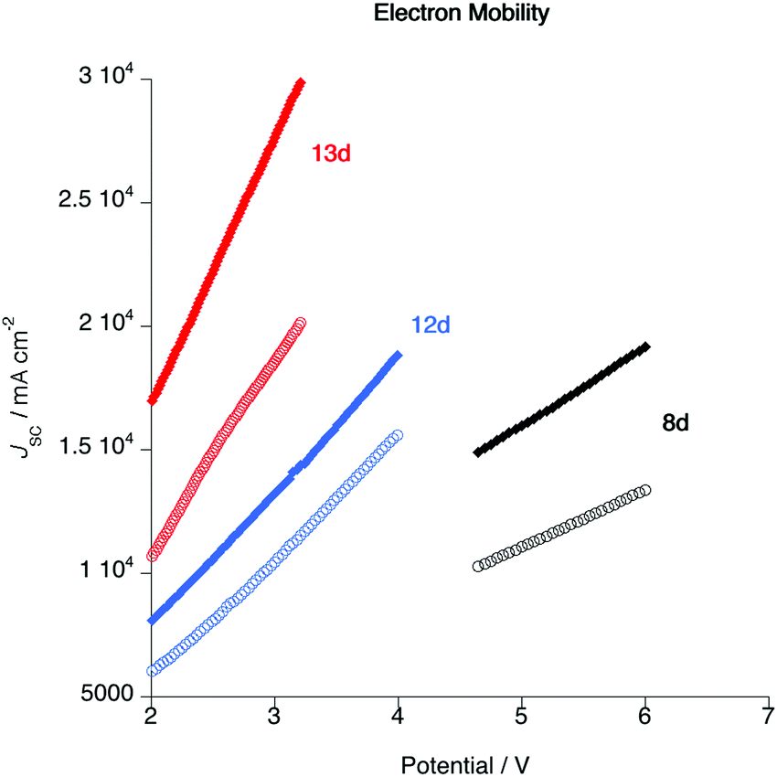 | ||
| Fig. 14 Plot of current density as a function of applied voltage for complexes 8d, 12d and 13d in the as-cast state (open circles) and after annealing in the liquid crystal phase (closed diamonds). | ||
| Sample | Condition | Mobility/cm2 V−1 s−1 | Thickness/nm | Processing temp./°C |
|---|---|---|---|---|
| 8d | As cast | 1.69 × 10⁻⁴ | 120 | 25 |
| Annealed | 4.05 × 10⁻⁴ | 90 | ||
| 12d | As cast | 4.68 × 10⁻⁴ | 100 | 25 |
| Annealed | 6.19 × 10⁻⁴ | 120 | ||
| 13d | As cast | 3.95 × 10⁻⁴ | 80 | 25 |
| Annealed | 5.89 × 10⁻⁴ | 120 |
The first important point about these data is that they show that following annealing the electron mobility increases. The process of annealing moved the material into the liquid crystal state and hence into a columnar arrangement giving better overlap of the complex π-systems. Of course, the annealing process does not create a monodomain sample and so the alignment is by no means perfect, but nonetheless the data demonstrate unequivocally that the mobility is enhanced as a result of liquid crystal organisation. It is then noteworthy that the drive voltage required for complex 8d is significantly greater than those for 12d and 13d. This observation is consistent with the intercolumnar separations obtained from the SAXS data, which imply that in complexes such as 8d, where there are only two alkoxy chains on the pincer ligand, there is back-to-back overlap of the pincer ligands in the columnar structure. The data also imply that for more inherently disc-like materials such as 12d and 13d, there is greater overlap of the complexes, which would be consistent with the lower drive voltage.
Then to evaluate the electroluminescent (EL) properties of these gold complexes, selected complexes were evaluated as the emitter in OLED devices, chosen to represent the range of complexes studied. Using solution processing, devices with the structure ITO/PEDOT:PSS/emitters/DPEPO/TmPyPB/CsF/Al§ were fabricated, with the emissive layer being a blend of polymer host (PVK:OXD-7 = 7:3) and the gold complex, the latter at concentrations of 5, 10 and 15 wt%. The device configuration and the molecular structures of the materials in the device are shown in Fig. S6 (ESI†), and the electroluminescence data obtained are collected in Table 6.
:OXD-7 (7:3)
| Complex | wt% | V on/V | L max/cd m−2 | CEmax/cd A−1 | PEmax/lm W−1 | EQEmax | Emission peak/nm (CIE coordinates) |
|---|---|---|---|---|---|---|---|
| 6a | 5 | 4.0 | 1458 | 22.01 | 12.51 | 6.72 | 508 (0.29, 0.58) |
| 10 | 4.4 | 1378 | 22.32 | 12.71 | 6.71 | 510 (0.31, 0.57) | |
| 15 | 4.4 | 1004 | 15.23 | 8.37 | 4.58 | 510 (0.31, 0.58) | |
| 6c | 5 | 4.4 | 1259 | 21.41 | 12.67 | 6.58 | 508 (0.31, 0.57) |
| 10 | 4.4 | 1370 | 17.31 | 9.69 | 5.24 | 508 (0.31, 0.56) | |
| 15 | 6.0 | 734 | 8.29 | 3.34 | 2.57 | 508 (0.31, 0.57) | |
| 8d | 5 | 4.0 | 1233 | 20.14 | 10.97 | 6.27 | 506 (0.32, 0.57) |
| 10 | 4.4 | 1229 | 13.76 | 6.97 | 4.25 | 508 (0.31, 0.57) | |
| 15 | 6.8 | 304 | 2.38 | 0.65 | 0.72 | 508 (0.30, 0.58) | |
| 10c | 5 | 3.6 | 1765 | 22.53 | 13.41 | 7.14 | 554 (0.47, 0.52) |
| 10 | 4.0 | 1441 | 21.18 | 11.73 | 6.94 | 556 (0.47, 0.51) | |
| 15 | 4.8 | 1142 | 9.71 | 4.00 | 3.14 | 558 (0.48, 0.51) | |
| 11a | 5 | 4.0 | 1705 | 21.31 | 12.45 | 6.82 | 554 (0.47, 0.51) |
| 10 | 4.4 | 1768 | 21.45 | 11.21 | 6.74 | 556 (0.47, 0.51) | |
| 15 | 4.8 | 1261 | 17.59 | 8.92 | 5.57 | 556 (0.47, 0.51) | |
| 12d | 5 | 4.4 | 1401 | 17.14 | 8.94 | 5.52 | 554 (0.47, 0.51) |
| 10 | 5.2 | 867 | 7.62 | 3.17 | 2.50 | 556 (0.47, 0.51) | |
| 15 | 6.4 | 494 | 4.45 | 1.62 | 1.46 | 556 (0.47, 0.51) | |
| 13d | 5 | 4.4 | 1191 | 18.04 | 10.10 | 5.69 | 554 (0.46, 0.51) |
| 10 | 4.4 | 1138 | 13.14 | 7.28 | 4.06 | 554 (0.47, 0.52) | |
| 15 | 4.4 | 911 | 11.75 | 6.58 | 3.66 | 554 (0.46, 0.52) | |
After optimisation, devices with 5 wt% of gold complex were found to give the best results (Fig. S8, ESI†) and so the electroluminescent (EL) properties are discussed in detail for this loading. Thus, all the devices exhibit intense emission in the range 400–800 nm (Fig. 15a) and it is of note that the EL emission is dependent on the number of alkoxy chains on the pincer ligand. Devices based on complexes 6a, 6c and 8a show emission maxima at about 508 and 538 nm, in addition to which there is an emission feature at ca. 458 nm attributed to the host matrix and arising from incomplete energy transfer between host and complex. On the other hand, the devices based on 10c, 11a, 12d and 13d show emission maxima at 554 nm with a shoulder at about 582 nm and here there is complete energy transfer between host and the emitters as evidenced by the absence of any higher-energy emissions (Fig. 15a). Compared to complexes 6a, 6c and 8a, the presence of the two additional chains on the pincer ligand leads to a red-shifted EL emission due to destabilisation of the HOMO, which helps the energy matching with the host matrix.
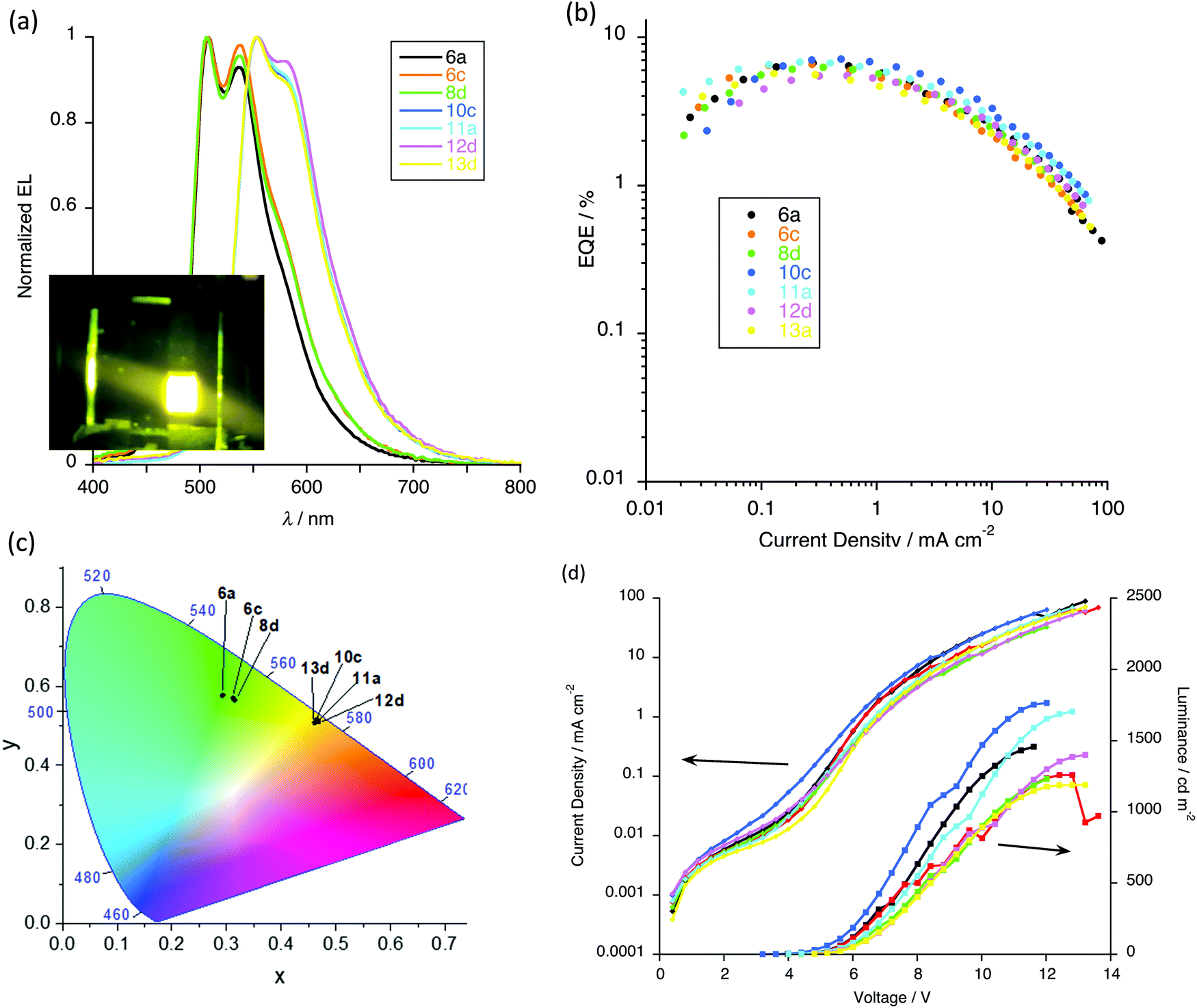 | ||
| Fig. 15 Device performance: (a) EL spectra with inset photograph of working device; (b) external quantum efficiency (EQE) as a function of current density (c) CIE coordinates; (d) current density and luminance as a function of voltage. | ||
The CIE coordinates (Fig. 15c) of these devices place them in the green and yellow region of the spectrum, as shown in Fig. 15a. With the increased dopant concentration, there is negligible change in the EL emission, implying the lack of formation of excimers or aggregate that might emit at lower energy.
As shown in Table 6 all devices exhibit relatively low turn-on voltages (at 1 cd m−2) in the range of 3.6–6.2 V, and satisfactory performance was achieved for the devices. With fewer flexible chains, complexes 6a (two-chain pincer ligand) and 10c (four-chain pincer ligand) showed the best device performance for each ‘family’. Thus, devices containing complex 6a gave an EQE of 6.7% (Fig. 15b), a luminance of 1458 cd m−2 (Fig. 15d) and a current efficiency 22.0 cd A−1 (Fig. S8, ESI†), while for complex 10c the same parameters were EQE = 7.1%, luminance = 1765 cd m−2 and current efficiency = 22.5 cd A−1. Device performance clearly decreases with the increased dopant concentrations because of the emission quenching at the higher concentrations. This device performance can be considered to be competitive with similar gold(III) complexes for which values ranging from 0.9%32,36 to 15.3%28 are found, the latter of which is the highest reported for a solution-processed device based on gold(III) emitters.
Conclusions
The incorporation of long alkoxy chains into the structure of Au(III) pincer compounds has a profound effect on their physical properties, notably the nature and stability of the LC phases that are induced are tuned by the substitution pattern of these chains on the pincer ligand. Further, the same structural modifications to the both the primary and secondary coordination sphere of the metal complex impart favourable photophysical properties. Thus, having two or four alkoxy chains on the backbone of the pincer ligand results in a bathochromic-shift in the absorption and emission wavelengths, reflecting the influence of the alkoxy groups on the ligand's electronic structure. However, analysis of the photophysical data indicates that modification of the secondary coordination sphere of the metal by placing four alkoxy groups on the pincer ligand also has a significant effect in reducing non-radiative decay processes, reflected in the high quantum yield for emission (up to 36%) and the longer lifetimes in this series.Electron mobility measurements demonstrate that, as expected for disc-like materials in columnar mesophases, the mobility is enhanced in the liquid crystal phase, but in this case the optimum level of the emitter in the device matrix is low (5%) so that that the beneficial conduction pathways are not accessed. Nonetheless, coupled with the observation that electroluminescent properties are certainly competitive with leading materials in this field, then modification of the primary and secondary coordination sphere of the Au(III) pincer complexes represents an important and dual-pronged strategy to develop and control the materials and photophysical properties of this class of complex.
Experimental
All experimental data relating to synthesis, single-crystal X-ray structures (cif and cifcheck files), physical measurements, computational chemistry (including methodology and Cartesian coordinates) and device fabrication are found in the ESI.†Dedication
It is with great pleasure that this paper is dedicated to Professor Emeritus Pablo Espinet from Valladolid, Spain. Liquid crystals and gold have been two of Pablo*s abiding interests where he has made seminal contributions over many years. The subject matter of this paper could not then be more appropriate as he moves to his own golden era, within which we wish him good health and great contentment, free from disorder!Conflicts of interest
There are no conflicts to declare.Acknowledgements
We thank the University of York (RRP) and the EPSRC (computational equipment used in this study, grants EP/H011455/1 and EP/K031589/1) for funding, Johnson Matthey for generous loans of gold salts, the Royal Society and the National Natural Science Foundation of China (51911530197, 51773021) for an International Exchange Award (DWB & YW), Rebecca Howarth for the preparation of some precursor ligands and Alice McEllin for recording some cyclic voltammetry data.References
- X. Wu, M. Zhu, D. W. Bruce, W. Zhu and Y. Wang, J. Mater. Chem. C, 2018, 6, 9848–9860 RSC.
- V. N. Kozhevnikov, B. Donnio and D. W. Bruce, Angew. Chem., Int. Ed., 2008, 47, 6286–6289 CrossRef CAS.
- V. N. Kozhevnikov, B. Donnio, B. Heinrich and D. W. Bruce, Chem. Commun., 2014, 50, 14191–14193 RSC.
- V. N. Kozhevnikov, B. Donnio, B. Heinrich, J. A. G. Williams and D. W. Bruce, J. Mater. Chem. C, 2015, 3, 10177–10187 RSC.
- C. T. Liao, H. H. Chen, H. F. Hsu, A. Poloek, H. H. Yeh, Y. Chi, K. W. Wang, C. H. Lai, G. H. Lee, C. W. Shih and P. T. Chou, Chem. – Eur. J., 2011, 17, 546–556 CrossRef CAS.
- A. Santoro, A. C. Whitwood, J. A. G. Williams, V. N. Kozhevnikov and D. W. Bruce, Chem. Mater., 2009, 21, 3871–3882 CrossRef CAS.
- D. Pucci, I. Aiello, A. Bellusci, A. Crispini, I. De Franco, M. Ghedini and M. La Deda, Chem. Commun., 2008, 2254–2256 RSC.
- D. Pucci, G. Barberio, A. Crispini, O. Francescangeli, M. Ghedini and M. La Deda, Eur. J. Inorg. Chem., 2003, 3649–3661 CrossRef CAS.
- N. S. S. Kumar, M. Z. Shafikov, A. C. Whitwood, B. Donnio, P. B. Karadakov, V. N. Kozhevnikov and D. W. Bruce, Chem. – Eur. J., 2016, 22, 8215–8233 CrossRef CAS.
- D. Pucci, G. Barberio, A. Bellusci, A. Crispini, B. Donnio, L. Giorgini, M. Ghedini, M. La Deda and E. I. Szerb, Chem. – Eur. J., 2006, 12, 6738–6747 CrossRef CAS.
- K. Binnemans, J. Mater. Chem., 2009, 19, 448–453 RSC.
- A. M. Prokhorov, A. Santoro, J. A. G. Williams and D. W. Bruce, Angew. Chem., Int. Ed., 2012, 51, 95–98 CrossRef CAS.
- A. Santoro, A. M. Prokhorov, V. N. Kozhevnikov, A. C. Whitwood, B. Donnio, J. A. G. Williams and D. W. Bruce, J. Am. Chem. Soc., 2011, 133, 5248–5251 CrossRef CAS.
- E. I. Szerb, A. M. Talarico, I. Aiello, A. Crispini, N. Godbert, D. Pucci, T. Pugliese and M. Ghedini, Eur. J. Inorg. Chem., 2010, 3270–3277 CrossRef CAS.
- A. M. Talarico, M. Ghedini, C. O. Rossi and E. I. Szerb, Soft Matter, 2012, 8, 11661–11669 RSC.
- Y. Wang, C. P. Cabry, M. Xiao, L. Male, S. J. Cowling, D. W. Bruce, J. Shi, W. Zhu and E. Baranoff, Chem. – Eur. J., 2016, 22, 1618–1621 CrossRef CAS.
- X. Wu, G. Xie, C. P. Cabry, X. Xu, S. J. Cowling, D. W. Bruce, W. Zhu, E. Baranoff and Y. Wang, J. Mater. Chem. C, 2018, 6, 3298–3309 RSC.
- M. O’Neill and S. M. Kelly, Adv. Mater., 2011, 23, 566–584 CrossRef.
- Á. Díez, S. J. Cowling and D. W. Bruce, Chem. Commun., 2012, 48, 10298–10300 RSC.
- V. W.-W. Yam, K. M.-C. Wong, L.-L. Hung and N. Zhu, Angew. Chem., Int. Ed., 2005, 44, 3107–3110 CrossRef CAS.
- V. K.-M. Au, D. P.-K. Tsang, K. M.-C. Wong, M.-Y. Chan, N. Zhu and V. W.-W. Yam, Inorg. Chem., 2013, 52, 12713–12725 CrossRef CAS.
- V. K.-M. Au, D. P.-K. Tsang, Y.-C. Wong, M.-Y. Chan and V. W.-W. Yam, J. Organomet. Chem., 2015, 792, 109–116 CrossRef CAS.
- V. K.-M. Au, K. M.-C. Wong, D. P.-K. Tsang, M.-Y. Chan, N. Zhu and V. W.-W. Yam, J. Am. Chem. Soc., 2010, 132, 14273–14278 CrossRef CAS.
- V. K.-M. Au, N. Zhu and V. W.-W. Yam, Inorg. Chem., 2013, 52, 558–567 CrossRef CAS.
- K. T. Chan, G. S. M. Tong, W.-P. To, C. Yang, L. Du, D. L. Phillips and C.-M. Che, Chem. Sci., 2017, 8, 2352–2364 RSC.
- G. Cheng, K. T. Chan, W.-P. To and C.-M. Che, Adv. Mater., 2014, 26, 2540–2546 CrossRef CAS.
- W.-L. Cheung, S.-L. Lai, M.-C. Tang, C.-H. Lee, M.-Y. Chan and V. W.-W. Yam, J. Mater. Chem. C, 2019, 7, 8457–8464 RSC.
- C.-H. Lee, M.-C. Tang, W.-L. Cheung, S.-L. Lai, M.-Y. Chan and V. W.-W. Yam, Chem. Sci., 2018, 9, 6228–6232 RSC.
- C.-H. Lee, M.-C. Tang, Y.-C. Wong, M.-Y. Chan and V. W.-W. Yam, J. Am. Chem. Soc., 2017, 139, 10539–10550 CrossRef CAS.
- S. K.-L. Siu, C. Y.-S. Chung and V. W.-W. Yam, J. Organomet. Chem., 2017, 845, 177–188 CrossRef CAS.
- S. K.-L. Siu, C. Po, K.-C. Yim, V. K.-M. Au and V. W.-W. Yam, CrystEngComm, 2015, 17, 8153–8162 RSC.
- M.-C. Tang, C. K.-M. Chan, D. P.-K. Tsang, Y.-C. Wong, M. M.-Y. Chan, K. M.-C. Wong and V. W.-W. Yam, Chem. – Eur. J., 2014, 20, 15233–15241 CrossRef CAS.
- M.-C. Tang, C.-H. Lee, M. Ng, Y.-C. Wong, M.-Y. Chan and V. W.-W. Yam, Angew. Chem., Int. Ed., 2018, 57, 5463–5466 CrossRef CAS.
- M.-C. Tang, M.-Y. Leung, S.-L. Lai, M. Ng, M.-Y. Chan and V. Wing-Wah Yam, J. Am. Chem. Soc., 2018, 140, 13115–13124 CrossRef CAS.
- M.-C. Tang, D. P.-K. Tsang, M. M.-Y. Chan, K. M.-C. Wong and V. W.-W. Yam, Angew. Chem., Int. Ed., 2013, 52, 446–449 CrossRef CAS.
- M.-C. Tang, D. P.-K. Tsang, M.-Y. Chan, K. M.-C. Wong and V. W.-W. Yam, Mater. Chem. Front., 2017, 1, 2559–2568 RSC.
- M.-C. Tang, D. P.-K. Tsang, Y.-C. Wong, M.-Y. Chan, K. M.-C. Wong and V. W.-W. Yam, J. Am. Chem. Soc., 2014, 136, 17861–17868 CrossRef CAS.
- W.-P. To, K. T. Chan, G. S. M. Tong, C. Ma, W.-M. Kwok, X. Guan, K.-H. Low and C.-M. Che, Angew. Chem., Int. Ed., 2013, 52, 6648–6652 CrossRef CAS.
- W.-P. To, D. Zhou, G. S. M. Tong, G. Cheng, C. Yang and C.-M. Che, Angew. Chem., Int. Ed., 2017, 56, 14036–14041 CrossRef CAS.
- B. Y.-W. Wong, H.-L. Wong, Y.-C. Wong, M.-Y. Chan and V. W.-W. Yam, Angew. Chem., Int. Ed., 2017, 56, 302–305 CrossRef CAS.
- K. M.-C. Wong, L.-L. Hung, W. H. Lam, N. Zhu and V. W.-W. Yam, J. Am. Chem. Soc., 2007, 129, 4350–4365 CrossRef CAS.
- K.-C. Yim, V. K.-M. Au, L.-L. Hung, K. M.-C. Wong and V. W.-W. Yam, Chem. – Eur. J., 2016, 22, 16258–16270 CrossRef CAS.
- K.-C. Yim, V. K.-M. Au, K. M.-C. Wong and V. W.-W. Yam, Chem. – Eur. J., 2017, 23, 5772–5786 CrossRef CAS.
- K.-C. Yim, E. S.-H. Lam, K. M.-C. Wong, V. K.-M. Au, C.-C. Ko, W. H. Lam and V. W.-W. Yam, Chem. – Eur. J., 2014, 20, 9930–9939 CrossRef CAS.
- D. Zhou, W.-P. To, Y. Kwak, Y. Cho, G. Cheng, G. S. M. Tong and C.-M. Che, Adv. Sci., 2019, 0, 1802297 CrossRef CAS.
- C.-H. Lee, M.-C. Tang, F. K.-W. Kong, W.-L. Cheung, M. Ng, M.-Y. Chan and V. W.-W. Yam, J. Am. Chem. Soc., 2020, 142, 520–529 CrossRef CAS.
- D. Zhou, W.-P. To, Y. Kwak, Y. Cho, G. Cheng, G. S. M. Tong and C.-M. Che, Adv. Sci., 2019, 6, 1802297 CrossRef CAS.
- D. Zhou, W.-P. To, G. S. M. Tong, G. Cheng, L. Du, D. L. Phillips and C.-M. Che, Angew. Chem., Int. Ed., 2020, 59, 6375–6382 CrossRef CAS.
- H. Beucher, S. Kumar, E. Merino, W.-H. Hu, G. Stemmler, S. Cuesta-Galisteo, J. A. González, J. Jagielski, C.-J. Shih and C. Nevado, Chem. Mater., 2020, 32, 1605–1611 CrossRef CAS.
- L.-K. Li, M.-C. Tang, S.-L. Lai, M. Ng, W.-K. Kwok, M.-Y. Chan and V. W.-W. Yam, Nat. Photonics, 2019, 13, 185–191 CrossRef CAS.
- S. Coco and P. Espinet, in Gold Chemistry, ed. F. Mohr, Wiley, 2009, ch. 8, pp. 357–396 Search PubMed.
- R. Chico, E. de Domingo, C. Domínguez, B. Donnio, B. Heinrich, R. Termine, A. Golemme, S. Coco and P. Espinet, Chem. Mater., 2017, 29, 7587–7595 CrossRef CAS.
- K.-H. Wong, K.-K. Cheung, M. C.-W. Chan and C.-M. Che, Organometallics, 1998, 17, 3505–3511 CrossRef CAS.
- A. F. Suleymanova, O. S. Eltsov, D. N. Kozhevnikov, A. O. Lantushenko, M. P. Evstigneev and V. N. Kozhevnikov, ChemistrySelect, 2017, 2, 3353–3355 CrossRef CAS.
- L. Ciano, N. Fey, C. J. V. Halliday, J. M. Lynam, L. M. Milner, N. Mistry, N. E. Pridmore, N. S. Townsend and A. C. Whitwood, Chem. Commun., 2015, 51, 9702–9705 RSC.
- R. Atencio, J. Barbera, C. Cativiela, F. J. Lahoz, J. L. Serrano and M. M. Zurbano, J. Am. Chem. Soc., 1994, 116, 11558–11559 CrossRef CAS.
- C. K. Lai, A. G. Serrette and T. M. Swager, J. Am. Chem. Soc., 1992, 114, 7948–7949 CrossRef CAS.
- F. Morale, R. W. Date, D. Guillon, D. W. Bruce, R. L. Finn, C. Wilson, A. J. Blake, M. Schröder and B. Donnio, Chem. – Eur. J., 2003, 9, 2484–2501 CrossRef CAS.
- J. W. Goodby, D. A. Dunmur and P. J. Collings, Liq. Cryst., 1995, 19, 703–709 CrossRef CAS.
- J. W. Goodby, R. J. Mandle, E. J. Davis, T. Zhong and S. J. Cowling, Liq. Cryst., 2015, 42, 593–622 CrossRef CAS.
- V. K.-M. Au, K. M.-C. Wong, N. Zhu and V. W.-W. Yam, J. Am. Chem. Soc., 2009, 131, 9076–9085 CrossRef CAS.
- K. M.-C. Wong, X. Zhu, L.-L. Hung, N. Zhu, V. W.-W. Yam and H.-S. Kwok, Chem. Commun., 2005, 2906–2908 RSC.
- A. J. Lees, Comments Inorg. Chem., 1995, 17, 319–346 CrossRef CAS.
- J. Fernandez-Cestau, B. Bertrand, A. Pintus and M. Bochmann, Organometallics, 2017, 36, 3304–3312 CrossRef CAS.
- M.-C. Tang, C.-H. Lee, S.-L. Lai, M. Ng, M.-Y. Chan and V. W.-W. Yam, J. Am. Chem. Soc., 2017, 139, 9341–9349 CrossRef CAS.
- L. Pan, B. Hu, X. Zhu, X. Chen, J. Shang, H. Tan, W. Xue, Y. Zhu, G. Liu and R.-W. Li, J. Mater. Chem. C, 2013, 1, 4556–4564 RSC.
- T. Wöhrle, I. Wurzbach, J. Kirres, A. Kostidou, N. Kapernaum, J. Litterscheidt, J. C. Haenle, P. Staffeld, A. Baro, F. Giesselmann and S. Laschat, Chem. Rev., 2016, 116, 1139–1241 CrossRef.
Footnotes |
| † Electronic supplementary information (ESI) available. CCDC 1991483–1991485. For ESI and crystallographic data in CIF or other electronic format see DOI: 10.1039/d0tc04839a |
| ‡ The nature of the triplet states in gold(III) pincer compounds has been investigated extensively (Chem. Sci., 2015, 6, 3026–3037, Inorg. Chem., 2015, 54, 3624–3630). Although such an approach is beyond the scope of the current study there is a good agreement between our experimental and calculated emission values. |
| § Anode = indium tin oxide; hole injection layer = PEDOT:PSS (poly(3,4-ethylenedioxythiophene):polystyrene sulfonate); host = PVK (poly(9-vinylcarbazole)) and OXD-7 (1,3-bis[2-tert-butylphenyl)-1,3,5-oxadiazo-5-yl]benzene); hole/exciton blocking layer = DPEPO (bis[2-(diphenylphosphino)phenyl]ether oxide); electron-transport layer = TmPyPB (1,3,5-tris(3-pyridyl-3-phenyl)benzene); electron-injecting layer = cesium fluoride; metal cathode = aluminium. |
| This journal is © The Royal Society of Chemistry 2021 |