 Open Access Article
Creative Commons Attribution 3.0 Unported Licence
A quantum dynamics study of the hyperfluorescence mechanism†
Yvelin
Giret
 ,
Julien
Eng
 ,
Thomas
Pope
and
Thomas
Penfold
 *
*
Chemistry-School of Natural and Environmental Sciences, Newcastle University, Newcastle Upon Tyne, NE1 7RU, UK. E-mail: tom.penfold@newcastle.ac.uk
First published on 21st December 2020
Abstract
Triplet state harvesting using thermally-activated delayed fluorescence (TADF) combined with efficient Förster resonant energy transfer (FRET) to a narrow fluorescent emitter is seen as a promising approach to achieve high efficiency and colour-purity in organic light-emitting diodes (OLEDs). In this work, we perform quantum chemistry and quantum dynamics simulations to model the so-called hyperfluorescence (HF) process between a carbene–metal–amide (CMA) molecule with a Au bridging metal (Au-Cz) and a narrow blue fluorescent emitter, 2,5,8,11-tetra-tert-butylperylene (TBPe). Our quantum dynamics simulations illustrate a FRET rate of ∼1010 s−1 indicating that it occurs on the picosecond timescale comparable with the ISC crossing rate of Au-Cz. This high FRET rate, which is most strongly dependent on the energy difference between the S1 states of the donor and acceptor molecules, is advantageous for devices as it encourages rapid triplet harvesting. In addition, the comparable FRET and intersystem crossing (ISC) rates, in contrast to most organic only systems, would facilitate studying this mechanism using photoexcitation. Besides the FRET rate, Förster radii are also estimated from the quantum dynamics simulations for different energy differences between the donor and acceptor molecules and are in quantitative agreement with the experimental estimations for different systems, showing that quantum nuclear dynamics simulation could be an important tool for enhancing our understanding of hyperfluorescence-based emitters.
1 Introduction
In the last decades there has been an intensive research effort conducted on developing and improving organic light-emitting diodes (OLEDs).1–3 The 1st generation of OLEDs were based on fluorescent molecules. However, these devices suffer from low internal quantum efficiency (IQE < 25%), as they are unable to harvest the non-emissive triplet states generated by charge recombination. This can be somewhat improved by exploiting inefficient triplet annihilation, but they still remain well short of 100% IQE.4 Full triplet harvesting was first achieved using iridium or platinum containing phosphorescent emitters, which exploits the large intrinsic spin orbit coupling (SOC) of these metals to harvest the triplet states.5Alternatively, in 2009, Adachi and coworkers proposed an OLED architecture based upon purely organic molecules exploiting thermally-activated delayed fluorescence (TADF).6 This mechanism relies on a triplet state being thermally activated to become iso-energetic with a singlet excited state such that it can undergo reverse intersystem crossing (rISC) to the singlet manifold. For molecules with small singlet–triplet energy gap TADF can become very efficient allowing a near 100% internal quantum efficiency without the use of rare earth elements.7–12 However, while able to achieve 100% IQE, both phosphorescence and TADF OLED emitters usually require the use of charge-transfer (CT) excited states. These CT states have inherently broad emission, with a typical full-width at half-maximum (FWHM) ∼70–120 nm, reducing the colour purity, making them difficult to use in displays, which require a FWHM < 30 nm. Consequently, commercial OLED displays employ lossy colour filters and/or expensive, difficult to fabricate optical microcavity structures to achieve sufficiently narrow line widths to satisfy colour requirements. This filtering of the original electroluminescence (EL) significantly reduces the external quantum efficiency (EQE) of the display, increases power consumption and shortens operational lifetime because the pixels need to run at higher brightness to compensate for this loss.
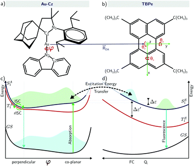
To overcome this, Nakanotani et al.13 proposed co-depositing a highly luminescent fluorophore into the emissive layer of a TADF-based OLEDs. The aim is to combine the advantages associated with efficient triplet harvesting using TADF emitters and the narrow emission of rigid fluorescent organic molecules. In their approach, refereed to as hyperfluorescence (HF) and illustrated in Fig. 1, charge recombination occurs on the TADF emitter which performs rISC to the singlet state, and then undergoes Förster energy transfer to the rigid fluorescent molecules which emits with high efficiency and colour purity. Using this approach the authors were able to demonstrate narrow fluorescence-based OLED achieving external quantum efficiencies as high as 18% for blue, green, yellow and red emission. In this study, the authors discussed the two regimes of HF accessed by either optical and electrical excitation. The latter is obviously more relevant in the context of device operation while the former is important in the context of material characterisation. Upon optical excitation, the authors reported that the excitons mainly formed on the host (SH1) and are resonantly transferred to the TADF-assistant molecule (SA1). From SA1, there is energy transfer into the emissive fluorescent molecule via FRET (SE1), giving rise to prompt fluorescence. Alternatively, ISC to the TA1 and then back to SA1 by rISC followed by FRET to SE1 gives rise to delayed fluorescence. The relative importance of both pathways depends on the rate of FRET compared to the ISC rate but for most organic molecules studied to date the former dominates, meaning there is limited triplet formation and therefore ISC/rISC. For electrical excitation, excitons are directly formed on the TADF-assistant molecule with a ratio of 25/75% for SA1 and TA1 respectively, in which case they observed a significantly larger contribution of the delayed fluorescence in the total emission.
In the HF approach, the fluorescence emitter can be chosen or designed14,15 to exhibit both a large oscillator strength, which minimises the excited state lifetime, and a narrow emission to increase the colour purity of the device. In addition, it has been shown that it is important to suppress Dexter energy transfer from the triplet states of TADF to the fluorophore and this can be achieved by either controlling the concentration of the TADF co-host16 or using Dendritic Fluorophores.17,18 In both cases, suppression of Dexter energy transfer can be achieved by increasing the spatial separation between the TADF co-host and the fluorophore.
To provide a deeper understanding into the HF mechanism, kinetic Monte Carlo (KMC) simulations were used to demonstrate that the IQE can be enhanced by aligning the appropriate energy levels and avoiding the formation of charge-transfer excitons, where the electron (or hole) is trapped on the TADF co-host and the other charge on the fluorophore.19 For the TADF co-host to be efficient, a small ΔES1–T1 is required, however as widely discussed in the TADF literature,11,12 when achieved with D–A molecules this reduces the radiative rate of the S1 state. The consequence of this in the framework of the HF mechanism would be to suppress the Förster energy transfer rate to the fluorophore. From this perspective, Lyskov et al.20 demonstrated that molecular vibrations and molecular orientation of the TADF co-host were important to increase the rate of the exciton transfer, the latter being similar to the well established spin–vibronic mechanism for TADF.21–23
In the vast majority of cases to date, HF devices have used organic TADF co-hosts. However, recently Yang et al.24 demonstrated high performance OLED with EQEs >20% using energy transfer from a carbene metal-amide (CMA) TADF co-host, where the bridging atom was Au (Au-Cz). Ultrafast optical measurements were used to propose that inter-fluorophore energy transfer occurs with efficiency >95% within 300 fs. Au-Cz has previously been shown to exhibit rapid singlet–triplet interconversion and high performance in OLED devices25 leading to a significant interest in developing this framework of emitters.26–31 On the basis of time-resolved electroluminescence (EL) and photoluminescence (PL) measurements, Di et al. demonstrated for Au-Cz rapid ISC to triplets (∼4 ps), and that CMA emission occurs almost entirely via a delayed-emission channel (∼350 ns).25 Importantly, the torsional motion around the bridge brings the Au-Cz to a (perpendicular) configuration showing a very small energy gap between the S1 and T1 states and very small oscillator strength, while the (co-planar) configuration shows a higher energy gap but also a higher oscillator strength. In other words, the co-planar geometry will promote emission and FRET while the perpendicular geometry will promote rISC.10,32,33
In this paper, we combine quantum chemistry and quantum dynamics calculations to provide a detailed understanding of the excited state properties required for efficient HF. We find a FRET rate of ∼1010 s−1 which is comparable with the ISC crossing rate of Au-Cz. This rate is most strongly dependent on the energy between the S1 states of the donor and acceptor molecules. Besides the FRET rate, Förster radii are also estimated from the quantum dynamics simulations and are in quantitative agreement with the experimental estimations for different systems.
2 Methodology
2.1 Computational details
All quantum chemistry calculations were performed using the QChem 5.0 quantum chemistry package34 with the exception of the spin–orbit coupling matrix elements which are calculated with the Amsterdam Modelling Suite (ADF) (2014).35,36 Density functional theory (DFT) and time-dependent density functional theory (TDDFT) were used to optimise the geometry of the ground state and the excited states, respectively. We used for all atoms all-electron Gaussian basis sets of triple zeta valence quality (def2-TZVP),37 except for the Au atom where an effective core potential (ECP) is used.38 All calculations are performed at the hybrid level with PBE0 exchange–correlation functional,39 and the TDDFT calculations within the Tamm–Dancoff approximation (TDA).40 Finally, calculations were performed with an implicit solvent model within the conductor-like screening model (COSMO) approach41 with the properties of toluene.2.2 Nuclear wavepacket propagation and model Hamiltonian
Throughout this study our quantum dynamics simulations were based upon a model Hamiltonian for Au-Cz and TBPe with the structure: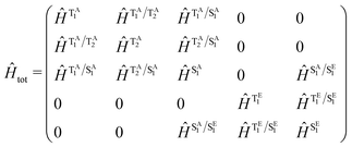 | (1) |
The quantum dynamics were performed using the multi-configurational time-dependent Hartree (MCTDH) method as implemented within the Quantics quantum dynamics package.43 The 2-dimensional spin–vibronic Hamiltonian model for the TADF emitter (Au-Cz molecule) was represented on a Fast Fourier Transform (FFT) grid of 1152 × 864 grid points for the torsion and the stretching modes, and where the torsional mode was set with periodic boundary conditions ranging from −π → π.32,33 For the torsion and the stretching modes, 7 single particle functions (SPFs) were used for TA1 and SA1, and 2 for TA2, SE1 and TE1. The four normal modes of TBPe were described using the multi-set formalism and combined in two pairs. 7 SPFs were used for SE1 and TE1, and 2 SPFs were used for all the states of Au-Cz. The evolution of the A-vector was calculated with the constant mean field integration scheme, and the SPFs were propagated with the Runge–Kutta integrator to fifth order (RK5). The initial wavepacket is placed onto the SA1 surface of Au-Cz. To better represent the distribution of φ associated with the flat nature of the potential along this motion, a wavepacket with a larger width along the torsional mode was adopted.
2.3 Kinetic model
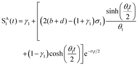
To interpret the results from the quantum dynamics and extract rate constants, we have built a kinetic model with three states, namely, SA1, SE1, and TA1, and their interactions, namely, the population transfer from SA1 to TA1 (ISC), from TA1 to SA1 (rISC), from SA1 to SE1 (EET), and from SE1 to SA1 (rEET). The kinetics of the population transfer are described by: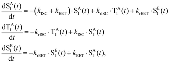 | (2) |
 | (3) |
where a = kISC, b = krISC, c = kEET, d = krEET, σ1 = a + b + c + d, σ2 = ad + bc + bd,
 ,
,  ,
,  , and
, and  . σ1 is defined as the sum of the first-order processes and σ2 as the sum of the second-order processes. γi represent the ratio of the second order processes populating each state, and θ1 represents a subtle competition between the different processes.
Throughout this work the radiative and non-radiative transitions of donor and acceptor molecules were not included as these channels were not included in the quantum dynamics and occur at longer timescales than considered within this work. Our model is a closed quantum system and therefore the kinetic model was setup to reflect the core processes present in the quantum dynamics. These equations above are used, with the rates kISC, krISC and kEET, obtained by performing a fit to the population kinetics obtained from the quantum dynamics simulations.
3 Results and discussion
3.1 Electronic structure
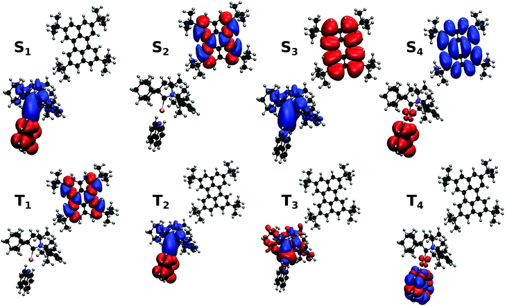
The electronic structure of Au-Cz has previously been discussed in detail and therefore readers are referred to ref. 32 and 33 for further details. In the ground state geometry of TBPe, the four lowest excited state are: T1 with an excitation energy of 1.90 eV, S1 with an excitation energy of 3.03 eV, T2 with an excitation energy of 3.17 eV, and T3 with an excitation energy of 3.38 eV. As shown in Table S1 (ESI†), the T1 and S1 states, which will be incorporated in the quantum dynamics, are both almost entirely composed of a HOMO → LUMO transition, and correspond to a local π → π* excitation. To study the EET mechanism between the two molecules, the reference geometry is taken as Au-Cz at its S1 optimised geometry (perpendicular) and TBPe at its S0 optimised geometry, which is the starting configuration for the EET mechanism and corresponds to the geometry of the S1 state of the whole system. The S2 state of the whole system at this geometry corresponds to the S1 state of the isolated TBPe molecule. The density differences between the excited states and the ground state for this reference geometry at an intermolecular distance of ∼24.2 Å are shown in Fig. 2. This also shows that the S3 and S4 states correspond to intermolecular CT states. Importantly, singlet–triplet conversation between these states (1CT and 3CT) was recently invoked as a significant loss pathway in HF-OLEDs.19 As shown in Fig. S1 (ESI†), the energy of these states increases with intermolecular distance and for separations greater than 30 Å the energy gap between these CT states and the S1 state is 0.6 eV. Given this energy gap, which is already likely to be underestimated due to the challenges of describe CT states with TDDFT,44 we do not include S3 and S4 states in the quantum dynamics. As a point of comparison, we have also calculated the electronic structure of Au-Cz–TBRb system. This was the combination of TADF co-dopant and fluorescence emitter recently used by Yang et al. in ref. 24, and generated narrow green emission in an OLED device. As shown in ESI,† this yields a similar electronic structure as the Au-Cz–TBPe system, albeit a slightly smaller EET coupling. Consequently, we focus on the Au-Cz–TBPe system as a way of generating a narrow blue HF setup.We now turn to the EET coupling, responsible for the HF mechanism. This coupling depends on several key parameters, namely, the distance between the donor and acceptor (RDA), the relative orientation of the two molecules described here by θx, θy and θz and the Au-Cz dihedral angle (φ) which has a large effect on the oscillator strength and the energy of the S1 state of Au-Cz.32,33 Besides φ we neglect the effect of all other intramolecular motions of either the Au-Cz or TBPe on the EET coupling. We first fix the relative orientation of the two molecules and calculate the coupling along RDA for the perpendicular and the co-planar geometries, as shown by the blue stars in Fig. 3a and b. Moreover, we compare the EET coupling to the Förster coupling calculated from eqn (S44) (ESI†) shown as red stars. As expected, the two coupling are in good agreement at larger distances (RDA ≥20 Å), but deviate from each other at short distances, as discussed in the ESI.† Subsequently, we fix the distance RDA at ∼24.2 Å where the two couplings are in agreement and calculate the couplings as a function of φ, as shown in Fig. 3c. The energy difference between the S1 and the T1 states of Au-Cz (black) is also plotted. This shows that it is possible to either have a small energy difference between the states, which exists for the perpendicular configuration of Au-Cz or a higher EET coupling, i.e. for the co-planar configuration. This arises because, as previously discussed,32,33 the dihedral angle φ strongly controls the radiative rate of the S1 state. This highlights the fact that for the Au-Cz molecule to be efficient for HF, it needs to keep some freedom over φ in order to harvest the triplets states in the perpendicular configuration and to transfer exciton energy to TBPe in the co-planar configuration.
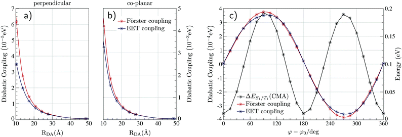 | ||
| Fig. 3 Strength of the EET and the Förster couplings between Au-Cz and TBPe as a function of the intermolecular distance RDA for the co-planar (a) and perpendicular geometry (b) of Au-Cz. (c) Strength of the EET and the Förster couplings between Au-Cz and TBPe as a function of the torsion angle φ of Au-Cz at RDA = 24.2 Å. This is also plotted with the S1–T1 energy gap between for Au-Cz. Couplings as a function of θx, θy and θz are shown in Fig. S2 (ESI†). | ||
Finally, we fix the position of Au-Cz in the perpendicular geometry and calculate the coupling along three inertia axis for TBPe (θx,θy,θz), as shown in Fig. S2 (ESI†). Except for θz where the two couplings are slightly shifted, Förster coupling is systematically higher than the EET coupling. These differences can arise from multipolar Coulomb effects which are neglected in the Förster theory, as discussed in the ESI.† The influence of these angles on the EET is much less than φ and therefore for the quantum dynamics, we only retain this dependences and fix the intermolecular distance at ∼15.7 Å. By doing so, RDA is high enough to stay outside the short-range regime related to intermolecular CT states and small enough to have a sufficiently large coupling.
3.2 The dynamics
Fig. 4a shows a prototypical example of the population kinetics for the SA1, TA1, TA2, and SE1 states during the first 100 ps after the initial excitation into the SA1 state for Δε ∼ −50 meV, Δε being defined as the energy difference between the SE1 state in the co-planar geometry and the SA1 state in the ground state geometry of TBPe (see Fig. 1). Δε = 0 corresponds to the perfect resonance between the two states. For the first ∼20 ps, we see clear oscillations between the SA1 and TA1 states, which corresponds to the wavepacket oscillating between the parallel and perpendicular geometries along the torsional angle potential of Au-Cz.32 On the other hand, the population in the SE1 state increases in a step-wise manner during the same duration and reaches a maximum of ∼20%. This highlights the competition between the ISC/rISC process in the perpendicular geometry and the EET process in the parallel geometry, because increases in SE1 are observed when Au-Cz is closer to the parallel geometry and ISC is unfavourable due to the larger energy gap between the singlet and triplet states. When fitted using the kinetic model outlined above this yields kISC = 1.7 × 10¹⁰ s−1 and kF = 4.8 × 10⁹ s−1. The former is in good agreement with previous work and experimental data,25,32 while the latter is consistent with a typical FRET rate.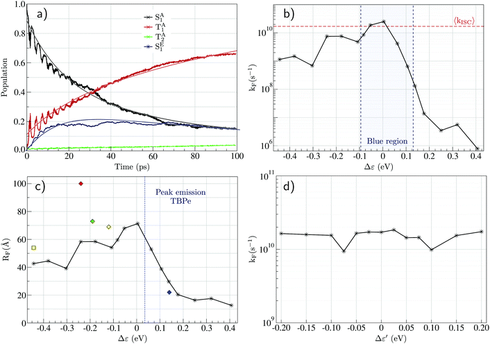 | ||
| Fig. 4 (a) Evolution of the excited state populations with time for Δε = −50 meV and RDA = 15.7 Å (see text): SA1 in black, TA1 in red, TA2 in green, and SE1 in blue, together with the fits (full lines) obtained from eqn (S23) (ESI†). (b) Evolution of the FRET rate constant (kF) estimated from quantum dynamics as a function of Δε. (c) Förster radius (RF) calculated from eqn (S48) (ESI†) as a function of Δε where the donor fluorescence lifetime is taken as τD = 350 ns.25 The diamonds are the experimental values for blue (ACRSA/TBPe), green (ACRXTN/TTPA), yellow (PXZ-TRZ/TBRb), and red (tri-PXZ-TRZ/CBP) emitters.13 The square is the experimental value for the yellow (CMA/TBRb) emitter.24 (d) Evolution of the FRET rate constant estimated from quantum dynamics as a function of Δε′ (see text). | ||
Fig. 4b shows the influence of Δε on the dynamics and in particular on the FRET rate, kF. As expected, the rate is largest when the two states are in resonance (i.e. Δε = 0). When Δε is negative (SA1 > SE1), the rate falls off slowly to ∼109 s−1 at Δε = −0.5. In contrast when Δε is positive (SA1 < SE1) the rate falls off exponentially due to the introduction of an energy barrier required to promote FRET. At this point, it is noted that in all cases, except the resonant conditions, kISC > kEET, this is advantageous for studying the HF mechanism using optical excitation, because in many systems (especially organic TADF emitters) kISC < kEET and therefore photoexcitation leads directly to EET without the ISC/rISC steps involved in HF occurring. Using the FRET rate, Fig. 4c shows the Förster radius calculated using our simulate kF as a function of Δε. These, with the exception of one point, are in quantitative agreement with experimental estimations for related and different systems,13,24 illustrating the potential for using the quantum dynamics to predict and refine the key properties of the components involved in HF.
Finally, we consider the potential interfering role of the TE1 state, indeed energy transfer into this state would be a detrimental loss pathway in the HF OLEDs. The calculated spin–orbit coupling matrix elements between the SE1 and TE1 states are very small (∼10−10 eV), and no contribution of the TE1 state appears in the population dynamics. To further investigate the possible role of spin–orbit coupling in the FRET mechanism, we artificially introduce a high coupling value (∼5 meV) and increase the energy of the TE1 state to make it closer to the SE1 energy, where the energy difference is called Δε′ = E(SE1) − E(TE1). It is noted that the energy gap can be used no only as an approximation for emitter with a smaller ΔES1–T1, but also where the S1 state is close in energy to higher lying triplet states as observed for TBPe. Fig. 2d shows the FRET rate as a function of Δε′. This shows that even with the large SOC of the TADF emitter, the fluorescence emitter and the small Δε′ this does not give rise to a significant amount of population transfer into the triplet states, which would be detrimental. Consequently, the predominant mechanism for formation of TE1 would be by direct charge recombination.
4 Discussion and conclusions
In this work, we have used quantum chemistry and quantum dynamics simulations to study a hyperfluorescence-based system composed of a TADF triplet harvester and a narrow organic fluorescent emitter with the objective of providing a detailed understanding on the competing mechanisms involved. The quantum chemistry simulations show that in the energy range of interest it is not only the lowest singlet and triplet excited states associated with each of the isolated molecules that are present. Intermolecular charge transfer states, where the electron (or hole) is trapped on the TADF co-host and the other charge on the fluorophore can be formed and lie in close proximity to the singlet and triplet states of the donor and acceptor. However, these states can be shifted to higher in energy by increasing the separation between the donor and acceptor. The absence of these states is strongly preferable as their formation has been implicated as a loss pathway in hyperfluorescence,19 by assisting the formation of triplet states on the fluorophore.Our quantum dynamics simulations find a typical FRET rate of ∼1010 s−1, indicating that it occurs on the picosecond timescale and is competitive with ISC. This rate yields Förster radii in quantitative agreement with previous experiments studying hyperfluorescence,13,24 indicating that the quantum dynamics can be used as a tool to understand the key factors controlling the HF mechanism. Despite this our FRET rate is substantially smaller than reported by Yang et al.,24 who reported that FRET on a similar system occurs in 300 fs. In this case, it would be significantly faster than usually encountered for FRET in OLEDs,45 which is expected to occur on the 100s of picoseconds to 10s of nanoseconds, as found in this work. In addition, as the ISC occurs in ∼10 ps, this would suggest that during photoexcitation negligible amount of triplet states are formed. However, the authors report a triplet population and use it to follow the lifetime of the rISC followed by FRET step which is ∼11 ns. This suggest that further spectroscopic studies are required to clarify the exact nature of FRET involving Au-Cz.
It is worth stressing that the fast ISC in Au-Cz means that it represents an excellent test case for HF. Indeed, for most organic molecules the ISC rate is at least an order of magnitude slower meaning that FRET will more frequently outcompete ISC. In this scenario photoexcitation of the TADF co-host will lead directly to FRET, without populating the triplet state. This is important for studying the HF mechanism using photoexcitation, as it enables the excited TADF emitter to relax into the triplet states to undergo rISC followed by FRET in a mechanism more closely related to that obtained from electro-excitation.
In summary, our quantum dynamics have provided insight into the HF mechanism. This has highlighted the relative importance of the Δε and Δε′ energy gaps, the molecular vibrations, namely the torsional angle of Au-Cz responsible for promoting its radiative rate and enhancing FRET and the dependence of the distance between the donor and acceptor units for controlling the presence of low lying intermolecular CT states. Indeed, it is Δε which is most important to the efficient of HF. In contrast the triplet state of the fluorescent emitter plays very little role, even when the coupling is increased. This suggests that the formation of this state, a detrimental loss pathway, will predominantly occur through direct charge recombination. Further work should focus on increasing the spectral overlap between the Au-Cz based donor and blue emitter, which would be best achieved by increasing the emission energy of Au-Cz and increase the FRET rate. However, it is stressed that as the typical FRET rate is ∼1010 s−1, the ISC and rISC on the TADF emitter remain the rate limiting step and needs to be enhanced to improve the efficiency of HF.
Conflicts of interest
There are no conflicts to declare.Acknowledgements
We acknowledge the EPSRC, Projects EP/P012388/1, EP/T022442/1 and EP/R021503/1 for funding. Data supporting this publication is openly available under an Open Data Commons Open Database License? Additional metadata are available at: http://10.25405/data.ncl.12752555. Please contact Newcastle Research Data Service at rdm@ncl.ac.uk for access instructions.References
- L. J. Rothberg and A. J. Lovinger, J. Mater. Res., 1996, 11, 3174–3187 CrossRef CAS.
- M. Baldo, D. O’brien, M. Thompson and S. Forrest, Phys. Rev. B: Condens. Matter Mater. Phys., 1999, 60, 14422 CrossRef CAS.
- C. Adachi, M. A. Baldo, M. E. Thompson and S. R. Forrest, J. Appl. Phys., 2001, 90, 5048–5051 CrossRef CAS.
- D. Y. Kondakov, Philos. Trans. R. Soc., A, 2015, 373, 20140321 CrossRef.
- H. Yersin, Highly efficient OLEDs with phosphorescent materials, John Wiley & Sons, 2008 Search PubMed.
- A. Endo, M. Ogasawara, A. Takahashi, D. Yokoyama, Y. Kato and C. Adachi, Adv. Mater., 2009, 21, 4802–4806 CrossRef CAS.
- C. Adachi, Jpn. J. Appl. Phys., 2014, 53, 060101 CrossRef.
- F. B. Dias, T. J. Penfold and A. P. Monkman, Methods Appl. Fluoresc., 2017, 5, 012001 CrossRef.
- M. Y. Wong and E. Zysman-Colman, Adv. Mater., 2017, 29, 1605444 CrossRef.
- J. Föller and C. M. Marian, J. Phys. Chem. Lett., 2017, 8, 5643–5647 CrossRef.
- T. Penfold, F. Dias and A. P. Monkman, Chem. Commun., 2018, 54, 3926–3935 RSC.
- J. Eng and T. J. Penfold, Chem. Rec., 2020, 20, 831–856, DOI:10.1002/tcr.202000013.
- H. Nakanotani, T. Higuchi, T. Furukawa, K. Masui, K. Morimoto, M. Numata, H. Tanaka, Y. Sagara, T. Yasuda and C. Adachi, Nat. Commun., 2014, 5, 4016 CrossRef CAS.
- Y. J. Kang, J. H. Yun and J. Y. Lee, Org. Electron., 2020, 78, 105604 CrossRef CAS.
- J. S. Jang, S. H. Han, H. W. Choi, K. S. Yook and J. Y. Lee, Org. Electron., 2018, 59, 236–242 CrossRef CAS.
- S. H. Han and J. Y. Lee, J. Mater. Chem. C, 2018, 6, 1504–1508 RSC.
- N. Aizawa, S. Shikita and T. Yasuda, Chem. Mater., 2017, 29, 7014–7022 CrossRef CAS.
- M. Jakoby, B. S. Richards, U. Lemmer and I. A. Howard, Phys. Rev. B, 2019, 100, 045303 CrossRef CAS.
- S. Gottardi, M. Barbry, R. Coehoorn and H. Van Eersel, Appl. Phys. Lett., 2019, 114, 073301 CrossRef.
- I. Lyskov, M. Etinski, C. M. Marian and S. P. Russo, J. Mater. Chem. C, 2018, 6, 6860–6868 RSC.
- T. J. Penfold, E. Gindensperger, C. Daniel and C. M. Marian, Chem. Rev., 2018, 118, 6975–7025 CrossRef CAS.
- M. K. Etherington, J. Gibson, H. F. Higginbotham, T. J. Penfold and A. P. Monkman, Nat. Commun., 2016, 7, 1–7 Search PubMed.
- J. Gibson, A. P. Monkman and T. J. Penfold, ChemPhysChem, 2016, 17, 2956–2961 CrossRef CAS.
- L. Yang, V. Kim, Y. Lian, B. Zhao and D. Di, Joule, 2019, 3, 1 CrossRef.
- D. Di, A. S. Romanov, L. Yang, J. M. Richter, J. P. Rivett, S. Jones, T. H. Thomas, M. A. Jalebi, R. H. Friend and M. Linnolahti, et al. , Science, 2017, 356, 159–163 CrossRef CAS.
- J. Feng, L. Yang, A. S. Romanov, J. Ratanapreechachai, A.-P. M. Reponen, S. T. Jones, M. Linnolahti, T. J. Hele, A. Köhler and H. Bässler, et al. , Adv. Funct. Mater., 2020, 1908715 CrossRef CAS.
- S. Shi, M. C. Jung, C. Coburn, A. Tadle, M. R. Daniel Sylvinson, P. I. Djurovich, S. R. Forrest and M. E. Thompson, J. Am. Chem. Soc., 2019, 141, 3576–3588 CrossRef CAS.
- R. Hamze, J. L. Peltier, D. Sylvinson, M. Jung, J. Cardenas, R. Haiges, M. Soleilhavoup, R. Jazzar, P. I. Djurovich and G. Bertrand, et al. , Science, 2019, 363, 601–606 CrossRef CAS.
- A. S. Romanov, C. R. Becker, C. E. James, D. Di, D. Credgington, M. Linnolahti and M. Bochmann, Chem. – Eur. J., 2017, 23, 4625–4637 CrossRef CAS.
- A. S. Romanov, L. Yang, S. T. Jones, D. Di, O. J. Morley, B. H. Drummond, A. P. Reponen, M. Linnolahti, D. Credgington and M. Bochmann, Chem. Mater., 2019, 31, 3613–3623 CrossRef CAS.
- J. Feng, A.-P. M. Reponen, A. S. Romanov, M. Linnolahti, M. Bochmann, N. C. Greenham, T. Penfold and D. Credgington, Adv. Funct. Mater., 2020, 2005438 Search PubMed.
- S. Thompson, J. Eng and T. Penfold, J. Chem. Phys., 2018, 149, 014304 CrossRef CAS.
- J. Eng, S. Thompson, H. Goodwin, D. Credgington and T. J. Penfold, Phys. Chem. Chem. Phys., 2020, 22, 4659–4667 RSC.
- Y. Shao, Z. Gan, E. Epifanovsky, A. T. Gilbert, M. Wormit, J. Kussmann, A. W. Lange, A. Behn, J. Deng and X. Feng, et al. , Mol. Phys., 2015, 113, 184–215 CrossRef CAS.
- G. t. Te Velde, F. M. Bickelhaupt, E. J. Baerends, C. Fonseca Guerra, S. J. van Gisbergen, J. G. Snijders and T. Ziegler, J. Comput. Chem., 2001, 22, 931–967 CrossRef CAS.
- C. F. Guerra, J. Snijders, G. T. te Velde and E. J. Baerends, Theor. Chem. Acc., 1998, 99, 391–403 Search PubMed.
- F. Weigend and R. Ahlrichs, Phys. Chem. Chem. Phys., 2005, 7, 3297–3305 RSC.
- D. Andrae, U. Haeussermann, M. Dolg, H. Stoll and H. Preuss, Theor. Chim. Acta, 1990, 77, 123–141 CrossRef CAS.
- C. Adamo and V. Barone, J. Chem. Phys., 1999, 110, 6158–6170 CrossRef CAS.
- S. Hirata and M. Head-Gordon, Chem. Phys. Lett., 1999, 314, 291–299 CrossRef CAS.
- A. Klamt and G. Schürmann, J. Chem. Soc., Perkin Trans. 2, 1993, 799–805 RSC.
- C.-P. Hsu, Z.-Q. You and H.-C. Chen, J. Phys. Chem. C, 2008, 112, 1204–1212 CrossRef CAS.
- M. H. Beck, A. Jäckle, G. A. Worth and H.-D. Meyer, Phys. Rep., 2000, 324, 1–105 CrossRef CAS.
- J. Eng, B. A. Laidlaw and T. J. Penfold, J. Comput. Chem., 2019, 40, 2191–2199 CAS.
- H. Fukagawa, T. Shimizu, Y. Iwasaki and T. Yamamoto, Sci. Rep., 2017, 7, 1–8 CrossRef CAS.
Footnote |
| † Electronic supplementary information (ESI) available. See DOI: 10.1039/d0tc04225k |
| This journal is © The Royal Society of Chemistry 2021 |

