 Open Access Article
Creative Commons Attribution 3.0 Unported Licence
Mixed polymer and bioconjugate core/shell electrospun fibres for biphasic protein release†
Inchirah
Adala
a,
Jopeth
Ramis
a,
Cynthia
Ntone Moussinga
a,
Isabella
Janowski
a,
Mahetab H.
Amer
 b,
Andrew J.
Bennett
c,
Cameron
Alexander
 a and
Felicity R. A. J.
Rose
 *a
*a
aSchool of Pharmacy, University of Nottingham, Nottingham, UK. E-mail: felicity.rose@nottingham.ac.uk
bSchool of Molecular and Cellular Biology, University of Leeds, Leeds, UK
cSchool of Life Sciences, University of Nottingham, UK
First published on 13th May 2021
Abstract
Effective regenerative medicine requires delivery systems which can release multiple components at appropriate levels and at different phases of tissue growth and repair. However, there are few biomaterials and encapsulation techniques that are fully suitable for the loading and controlled release of multiple proteins. In this study we describe how proteins were physically and chemically loaded into a single coaxial electrospun fibre scaffold to obtain bi-phasic release profiles. Cyto-compatible polymers were used to construct the scaffold, using polyethylene oxide (PEO) for the core and polycaprolactone (PCL) reacted or mixed with (bis-aminopropyl)polyether (Jeffamine ED2003; JFA) for the shell. Horseradish peroxidase (HRP), a model protein, was loaded in the core and functionalised onto the scaffold surface by coupling of protein carboxyl groups to the available polymer amine groups. Fibre morphologies were evaluated by scanning electron microscopy (SEM) and transmission electron microscopy (TEM) and functional group content was determined using X-ray photoelectron spectroscopy (XPS) and time-of-flight secondary ion mass spectrometry (TOF SIMS). Hydrophobicity profiles of the fibres before and after protein loading were evaluated by water contact angle (WCA) and the mechanical properties of the electrospun scaffolds were determined by performing tensile tests. The electrospun fibre scaffolds generated by reacting PEO/PCL with 1,6-diaminohexane and those from mixing PEO/PCL with JFA were further characterised for protein conjugation and release. Fibres prepared by the mixed PEO/PCL/JFA system were found to be the most appropriate for the simultaneous release of protein from the core and the immobilisation of another protein on the shell of the same scaffold. Moreover, JFA enhanced scaffold properties in terms of porosity and elasticity. Finally, we successfully demonstrated the cytocompatibility and cell response to protein-loaded and -conjugated scaffolds using HepG2 cells. Enhanced cell attachment (2.5 fold) was demonstrated using bovine serum albumin (BSA)-conjugated scaffolds, and increased metabolic activity observed with retinoic acid (RA)-loaded scaffolds (2.7 fold).
1. Introduction
Biotherapeutics, such as proteins and peptides, are of increasing interest for the treatment of many diseases and also in the field of regenerative medicine.1 For tissue engineering purposes, such biologicals allow the mimicking of the natural tissue environment where many of these molecules, such as growth factors and cytokines, are secreted by cells and sequestered within the extracellular matrix (ECM).1 These molecules are necessary for cell–cell communication, modulation of cell attachment and to drive cell differentiation or maturation.2,3 They all function in a synchronised manner in order to achieve normal tissue function and guide successful tissue repair or regeneration. Hence, the use of single protein delivery systems in tissue engineering is inherently limiting and does not represent the physiological environment.2,4 There is accordingly an urgent need to develop delivery systems which are effective for multiple proteins,5 ideally in which the individual proteins can be released at distinct rates.6Protein delivery is a challenge due to the limited stability during formulation, storage, in vitro and in vivo release.7 Proteins can breakdown due to environmental factors such as low or high pH, ionic strength, or inactivation by enzymes.7 To this end, a number of materials have been used to protect therapeutic proteins by physical separation from any unfavourable environments in an organism prior to delivery.7 The chosen biomaterial has to be compatible with the protein, and also amenable to an encapsulation technique.7 In the case of multiple protein delivery, finding a suitable biomaterial and an encapsulation technique compatible with multiple proteins remains challenging.
Amongst the many technologies for preparing scaffold materials for 3D cell culture and tissue growth, coaxial electrospinning has emerged as a promising approach. This method can produce well-defined and multi-component fibres, with fibre diameters ranging from tens of nanometres to multi-microns.8,9 These fibres offer properties important for cell culture including a large surface area, high molecular permeability through the scaffold, and tuneable porosity.10 Furthermore, coaxial electrospinning enables the formulation of differentially functionalised core–shell fibres and this in turn can lead to significant practical advantages.11,12 These are that diverse guest molecules can be partitioned within and on the layered core–shell structures, enabling, in principle, the simultaneous or phased release of multiple cell-signalling or other bioactive agents. These can range from hydrophobic small molecule inhibitors through to hydrophilic biomacromolecules such as proteins and nucleic acids.13 In addition, through variation of the individual materials used for the core and shell regions of the fibres, coaxial electrospinning allows for fine control in the release of encapsulated agents to a much greater extent than for fibres produced by single-nozzle electrospinning.14
In this study, proteins were physically and chemically loaded into and onto coaxial electrospun fibres in order to obtain bi-phasic release profiles. Proteins were covalently attached on the surface of the fibre (i.e. the shell), where cells can access the protein via direct contact. This mimics the interaction between cells and ECM-bound growth factors found in vivo.15 While in the core of the fibre, the proteins were physically blended within the polymer to allow subsequent continuous release to the surrounding environment.
Cytocompatible polymers were used to construct the scaffold, in this case polyethylene oxide (PEO) for the core and a polycaprolactone (PCL)/O,O′-bis(2-aminopropyl)polypropylene glycol-block-polyethylene glycol-block-polypropylene glycol (Jeffamine, JFA) mixture for the shell. PEO was chosen in order to load bioactive molecules in the fibre core without exposing them to organic solvents. PCL was selected owing to its mechanical properties and high solubility in organic solvents typically used in electrospinning processes.16,17 However, PCL does not contain functional groups that facilitate high yield protein conjugation. Therefore, two main approaches for covalent attachment of proteins at the scaffold surface were evaluated, (a) the aminolysis of PEO/PCL scaffold post electrospinning by reaction with 1,6-diaminohexane and (b) the use of a PCL/JFA blend. JFA was chosen as it contains two amine-terminal groups attached to each end of a polyether backbone.18 In addition to the reactive NH2 termini, the hydrophilic polyether backbone was deemed suitable in order to improve the scaffold's flexibility and wettability. Despite the interesting properties of JFA polymers, only a few studies have reported their use in electrospinning19,20 and none in coaxial-electrospinning. In our work, we showed that the use of JFA in a coaxial electrospun scaffold, facilitates the production of a multiple protein delivery system, in comparison to aminolysis and other multi-step treatments such as layer by layer functionalization, polymer coating or grafting21 Additionally, we demonstrated that JFA enhanced scaffold properties in terms of porosity and elasticity.
2. Materials and methods
2.1. Preparation of PEO/PCL and PEO/PCL/JFA core–shell electrospun membranes
Pre-weighed polyethylene oxide (PEO) (200 kDa, 400 kDa, and 900 kDa), polycaprolactone (PCL) (80![[thin space (1/6-em)]](https://www.rsc.org/images/entities/char_2009.gif) 000 g mol−1), O,O′-bis(2-aminopropyl)polypropylene glycol-block-polyethylene glycol-block-polypropylene glycol (Jeffamine, 1900 g mol−1; JFA) (all purchased from Sigma Aldrich, UK) were dissolved in different solvent systems, respectively, as shown in Table 1.
000 g mol−1), O,O′-bis(2-aminopropyl)polypropylene glycol-block-polyethylene glycol-block-polypropylene glycol (Jeffamine, 1900 g mol−1; JFA) (all purchased from Sigma Aldrich, UK) were dissolved in different solvent systems, respectively, as shown in Table 1.
| Polymer | Concentration (%) | Solvent (v/v) | Flow rate | Distance (cm) | Voltage (kV) |
|---|---|---|---|---|---|
| PEO(900 kDa)/PCL | |||||
| PEO(900 kDa) | 4 | DIW | 200 (μL h−1) | 23 | 16 |
| PCL | 10 | Chloroform/DMF (8![[thin space (1/6-em)]](https://www.rsc.org/images/entities/char_2009.gif) : :![[thin space (1/6-em)]](https://www.rsc.org/images/entities/char_2009.gif) 2) 2) |
1.5 (mL h−1) | ||
| PEO(400 kDa)/PCL | |||||
| PEO(400 kDa) | 6 | DIW | 200 (μL h−1) | 23 | 23 |
| PCL | 10 | Chloroform/DMF (8![[thin space (1/6-em)]](https://www.rsc.org/images/entities/char_2009.gif) : :![[thin space (1/6-em)]](https://www.rsc.org/images/entities/char_2009.gif) 2) 2) |
1.5 (mL h−1) | ||
| PEO(200 kDa)/PCL | |||||
| PEO(200 kDa) | 16 | DIW | 200 (μL h−1) | 23 | 16 |
| PCL | 10 | Chloroform/DMF (8![[thin space (1/6-em)]](https://www.rsc.org/images/entities/char_2009.gif) : :![[thin space (1/6-em)]](https://www.rsc.org/images/entities/char_2009.gif) 2) 2) |
1.5 (mL h−1) | ||
| PEO(200 kDa)/PCL/JFA | |||||
| PEO(200 kDa) | 16 | DIW | 200 (μL h−1) | 13 | 13 |
| PCL/JFA | 10 | Chloroform/DMF (8![[thin space (1/6-em)]](https://www.rsc.org/images/entities/char_2009.gif) : :![[thin space (1/6-em)]](https://www.rsc.org/images/entities/char_2009.gif) 2) 2) |
1.4 (mL h−1) | ||
Bioactive molecules horseradish peroxidase (HRP) (Sigma Aldrich, UK, P8375) and retinoic acid (RA) (Sigma Aldrich, UK), were mixed and homogenised with deionised water prior to adding PEO 200 kDa.
For the core, solutions of PEO were prepared at different concentrations using de-ionised water as solvent: 16% w/v PEO 200 kDa, 6% w/v PEO 400 kDa and 4% w/v PEO 900 kDa. A stock solution of RA at 100 mM in DMSO was prepared. HRP was dissolved and RA further diluted, prior to electrospinning, in PEO to a final concentration of 15.7 μg mL−1 and 10 μM respectively. For the shell, chloroform and N,N-dimethylformamide (DMF) were used at a ratio of (8![[thin space (1/6-em)]](https://www.rsc.org/images/entities/char_2009.gif) :
:![[thin space (1/6-em)]](https://www.rsc.org/images/entities/char_2009.gif) 2) for dissolving 10% w/w PCL with increasing JFA concentrations of 5%, 6%, 7.5%, 30%, 45% and 60% relative to PCL.
2) for dissolving 10% w/w PCL with increasing JFA concentrations of 5%, 6%, 7.5%, 30%, 45% and 60% relative to PCL.
Solutions were stirred overnight at room temperature and their conductivity measured using a conductivity meter (Mettler Toledo). Solutions were then loaded into separate disposable plastic syringes for electrospinning and a dual syringe pump was used to deliver the core and shell fluids independently using an electrospinning machine (EC-CLI, IME Technologies, Geldrop, Netherlands). The electrospun fibres were collected on aluminium foil placed onto a grounded rotating mandrel. The applied voltage and the distance between the tip of the spinneret and the collector varied depending on the polymer system. Electrospinning parameters are shown in Table 1.
2.2. Release study of the core molecule HRPCM
The HRP for the release study is denoted as HRPCM. The release behaviours from pre-weighed loaded fibres were carried out in a shaking incubator at 37 °C for 22 days in phosphate buffer solution (PBS; pH 7.4) (Sigma Aldrich, UK). At predefined time intervals, 1 mL of the release medium was withdrawn and replaced with an equal volume of fresh PBS pH 7.4 each time. Protein concentration was determined using the bicinchoninic acid (BCA) assay using the Micro BCA protein assay kit (Thermoscientific, UK) and following the manufacturer's instructions for protein detection in microplate wells.Activity post-release was measured using the 2,2′-azino-bis(3-ethylbenzothiazoline-6-sulfonic acid) diammonium salt (ABTS) assay (Sigma Aldrich, UK). Sample (100 μL) was mixed with 100 μL of ABTS, 10 μL of SDS 0.5% (w/v; Sigma Aldrich, UK) was added to stop the reaction after 15 min, then the absorbance measured at 405 nm using a Tecan Infinite M200 plate reader (Tecan Reading, UK).
Data were obtained from three independent experiments (n = 3).
2.3. Surface functionalisation and HRPSM conjugation
PEO/PCL scaffolds were aminolyzed by incubation in 10% (w/w) 1–6 diaminohexane in isopropanol for different time intervals (i.e. 30 min, 1 h 00, 1 h 30, 2 h 00, 2 h 30, 3 h 00) at 37 °C in a shaking incubator. The scaffolds were washed and kept in isopropanol for 10 min, then washed a further five times in isopropanol, and deionised water. Subsequently, the scaffolds were dried in a chemical fumehood at RT for 24 h.22,23HRP was also used as a model protein for surface conjugation and is denoted HRPSM. HRPSM was conjugated onto the scaffold surface by reacting the carboxyl groups of the protein with the amine groups introduced to the scaffold via JFA incorporation or aminolysis of the surface layers of the PCL scaffolds. Aminolyzed PEO/PCL and PEO/PCL/JFA scaffolds were cut into disks (10 mm in diameter) and placed in HRP solution (50 μg mL−1) for 30 min at 37 °C in a shaking incubator. The scaffolds were then covered with 250 μL of 50 mM MES solution buffer (pH = 6), 125 μL of 68 mM EDC and 125 μL 68 mM S-NHS as a single solution (all from Sigma Aldrich, UK). This technique is referred to as EDC-NHS treatment. The samples were then placed on a shaker at RT for different time intervals (i.e. 1 h, 2 h, 3 h, 4 h). Finally, the scaffolds were washed in PBS, and the activity of the conjugated HRP was determined over time by covering the samples with 3,3′,5,5′-tetramethylbenzidine substrate solution (TMB) (Sigma Aldrich, UK) for 15 min. Images of the scaffolds were taken using a digital camera and colour intensity was quantified using ImageJ 1.52 h software from the ImageJ package Fiji.24 Data were obtained from three independent experiments (n = 3).
2.4. Bovine serum albumin (BSA) conjugation
PEO/PCL/JFA scaffolds were cut into discs of 10 mm in diameter, placed in BSA (Sigma Aldrich, UK) solution (0.4mg mL−1) for 30 min at 37 °C in a shaking incubator. The scaffolds were then covered with 250 μL of 50 mM MES solution buffer (pH = 6), 125 μL of 68 mM EDC and 68 mM S-NHS as a single solution (all from Sigma Aldrich, UK). The samples were then placed on a shaker at RT for an hour and washed in PBS. Data were obtained from three independent experiments (n = 3).2.5. Scaffold characterisation
In order to study internal pore size, the scaffolds were cryo-frozen in liquid nitrogen and ruptured before sputter coated with gold. Average pore diameter was calculated upon five different SEM images, from which 100 measurements in total were analysed using ImageJ 1.52 h software from the ImageJ package Fiji.24
Transmission electron microscopy (TEM, FEI Tecnai G2 12 Biotwin) was carried out to determine the core/shell structure of the coaxial fibres. Images were recorded at 100 kV.
2.6. Scaffold cytocompatibility and biological response
The cellular responses to the scaffolds, with and without loaded bioactives, were evaluated by investigating cell attachment and albumin secretion. For both experiments, human HepG2 cells (ATCC, UK) were used from passage 6 to 10. Cells were cultured in Minimum Essential Medium (MEM) supplemented with foetal bovine serum (10% v/v), non-essential amino acid (1% v/v), L-glutamine (1% v/v), 100 units per mL penicillin, 100 μg mL−1 streptomycin and 100 μg mL−1 of gentamicin/amphotericin (AB/AM) (all from Sigma Aldrich, UK; HepG2 complete culture media). Cells were maintained at 37 °C, 5% CO2 in air at 95% relative humidity. Cells were expanded in tissue culture flasks, and media was changed every three days. When 80–90% confluency was reached, cells were trypsinised with trypsin (0.25% v/v)/ethylenediamine-tetraacetic acid (0.02% v/v EDTA) solution. Cells were then centrifuged at 500 x g using a Sigma Laboratory centrifuge 2–16 K (Scientific Laboratory Supplies, UK) and the pellet was resuspended in complete HepG2 culture media.Prior to cell seeding, 1.13 cm2 diameter scaffolds were cut, placed in inserts, sterilised using a UV lamp (254 nm) for 30 min and placed in a non-tissue culture treated 12 well plate (Corning, UK). Cells were seeded at 100![[thin space (1/6-em)]](https://www.rsc.org/images/entities/char_2009.gif) 000 cells on various scaffolds and incubated at 37 °C, 5% CO2 in air in HepG2 complete culture media for a period of 3 hours and six days respectively prior to assessment for cell attachment and ELISA.
000 cells on various scaffolds and incubated at 37 °C, 5% CO2 in air in HepG2 complete culture media for a period of 3 hours and six days respectively prior to assessment for cell attachment and ELISA.
| Swelling ratio % Q = (Ww − Wd)/Wd × 100 |
Scaffold degradation in culture conditions was determined by placing pre-weighed scaffolds in 2 mL PBS in a shaking incubator at 37 °C, 5% CO2 in air at 95% relative humidity. At different time intervals (5, 10 and 15 days) scaffolds were dried thoroughly and weighed again in order to determine weight loss. Weight loss was calculated using the following formula:
| Weight loss % = (Wo − Wt)/Wo × 100 |
2.7. Statistical analysis
Statistical analyses were performed using GraphPad Prism 7.03 software (San Diego, CA). For the physicochemical characterisation, groups were compared using an unpaired Student's t-test measured in triplicate. For cell experiments, triplicate technical replicates (n = 3) were carried out at N = 3 independent experiments with ANOVA used for analysis. A value of p ≤ 0.05 was considered significant, and graphs are reported as mean and standard deviation (SD).3. Results and discussion
3.1 Scaffold morphology
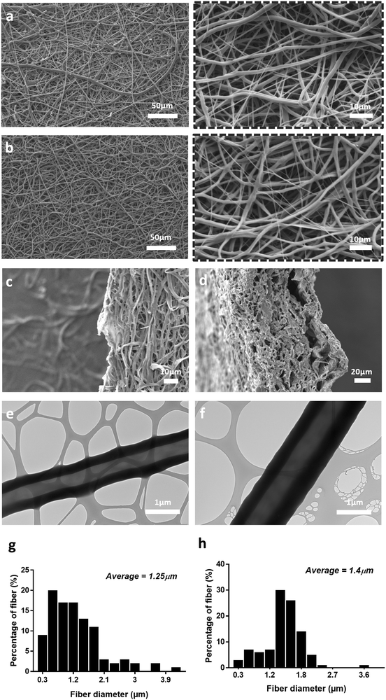
For both scaffolds fabricated with PEO 200 kDa and PEO 400 kDa, the distinct core/shell structure of the fibres was confirmed by TEM (Fig. 1e and Fig. S1c, ESI†). However, when PEO molecular weight was increased further to 900 kDa, no clear core/shell structure was observed under TEM, despite the presence of a stable jet during the electrospinning process (Fig. S1d, ESI†). PEO 200 kDa was chosen over PEO 400 kDa for further development of the scaffold because the jet quality was found to be more stable for the PEO 200 kDa during the electrospinning process.
In Fig. 1, SEM images of PEO/PCL scaffolds display a limited internal pore structure whereas PEO/PCL/JFA scaffolds presented pores ranging from 1 to 16 μm, with an average pore size of 6 μm (Fig. S2, ESI†). This can be explained partially by the different electrospinning parameters used for both systems. A longer distance between the nozzle and collector was used for PEO/PCL, which resulted in a broader and less porous scaffold. The PEO/PCL/JFA jet was unstable with a longer distance and so this had to be reduced. Different JFA concentrations were tested during the optimisation process using similar electrospinning parameters to those used for PEO/PCL initially (with PEO 200 kDa). Changes were then made to these parameters until the most stable jet was obtained for all scaffolds with changing JFA content. It was found that the PEO/PCL/JFA scaffold morphology changed significantly depending on JFA concentration.
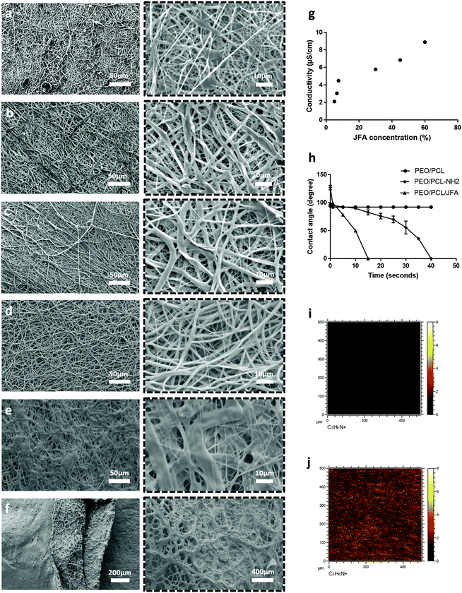
At 30% JFA, the scaffold presented smooth homogeneous fibres without defects (Fig. 1b) and a slightly higher average diameter of 1.4 μm in comparison to PEO/PCL fibres (1.25 μm) (Fig. 1g and h). Similarly to PEO/PCL scaffolds, distinct core/shell structures were observed (Fig. 1f). During electrospinning, the Taylor cone (TC) was highly stable without interruption of the jet. When the JFA concentration was below or above 30%, then the jet was unstable and the resulting scaffold was non-homogeneous with variable fibre diameter and beading (Fig. 2). For example, in the cases of 5%, 6% and 7.5% JFA concentrations, the stability of the TC decreased and beads were formed (Fig. 2a–c). However, the jet became more stable and continuous when JFA concentrations increased. In fact, SEM images show a more homogeneous scaffold morphology for higher JFA concentrations with fewer beads observed. However, when the JFA concentration was above 30%, the TC was disrupted by continuous fibre formation between the coaxial nozzle and the collector, resulting in the formation of a smaller scaffold with non-homogeneous fibres (Fig. 2e and f).
It was found that PCL/JFA solutions increased in conductivity with increasing JFA concentration levels. For the lowest concentrations (5%, 6%, 7.5%), the conductivity was too low for electrospinning resulting in droplet formation. In contrast, the conductivity was high for the highest JFA concentrations (45%, 60%; 6.8 μS cm−1, 8.8 μS cm−1) (Fig. 2g) with resulting continuous, irregular fibres. Among the concentrations investigated, it was thus identified that the optimal concentration level was 30% JFA (Fig. 2d), and this was the formulation used for the rest of this study.
3.2 Scaffold surface analysis
3.3 Mechanical properties of PEO/PCL and PEO/PCL/JFA scaffolds
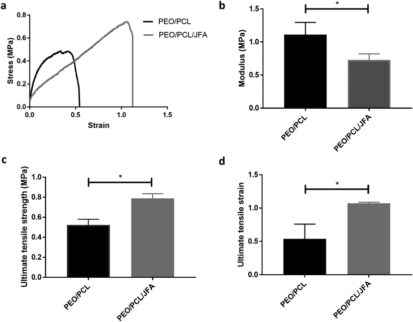
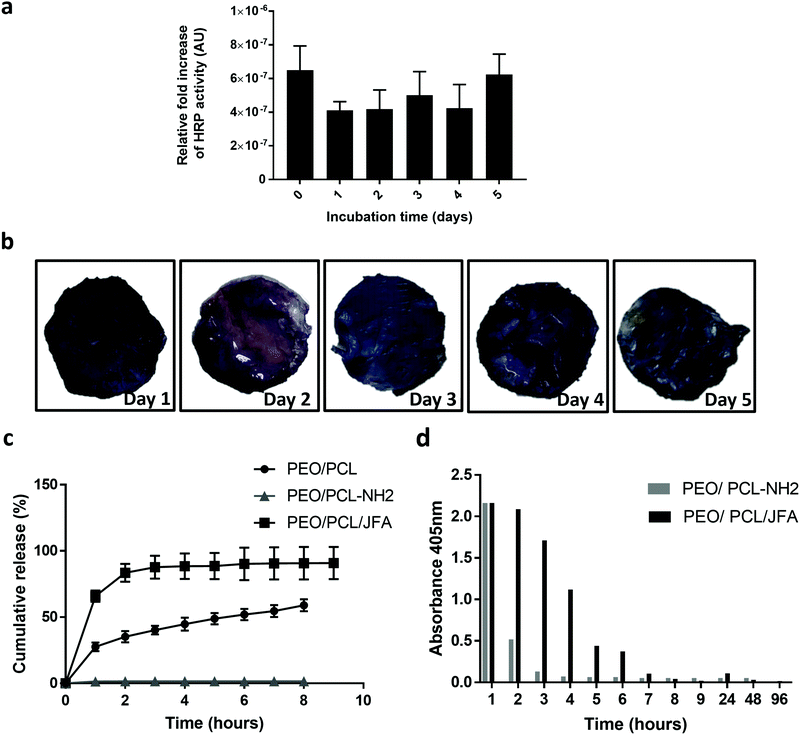
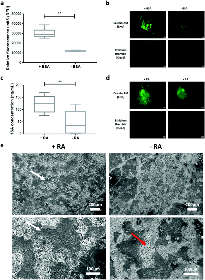
Tensile properties of PEO/PCL and PEO/PCL/JFA scaffolds were determined by stress–strain measurements (Fig. 3). These data show that the mechanical properties of the scaffolds changed when JFA was introduced into the blend. For example, the inclusion of JFA significantly reduced the modulus from 1.11 MPa to 0.73 MPa (Fig. 3b), meaning that the elasticity of the modified scaffold was greater than for the PEO/PCL alone scaffold. It is likely that incorporation of JFA plasticised the PCL matrix and reduced polymer chain–chain interaction enthalpies. In contrast, the aminolysis procedure with 1,6-diaminohexane resulted in the reduction of the elasticity of the scaffold, compared with the untreated scaffold. This we attribute to cross-linking between adjacent polyester chains as the diamine reacted, leading to enhanced rigidity, as well as a reduction in PCL chain length as ester bonds were replaced with amides.Weight loss analysis was used to assess the degradation profile of the PEO/PCL/JFA scaffold for 15 days, which is the longest time we anticipate the use of the scaffold (Fig. S8b, ESI†). The scaffold remained intact over this period of time, which was further confirmed by SEM images post cell culture (Fig. 6e).
3.4 PEO/PCL-NH2 scaffolds: conjugation of shell molecule HRPSM and release of core molecule HRPCM
3.5 PEO/PCL/JFA scaffolds: conjugation of shell molecule HRPSM and release of core molecule HRPCM
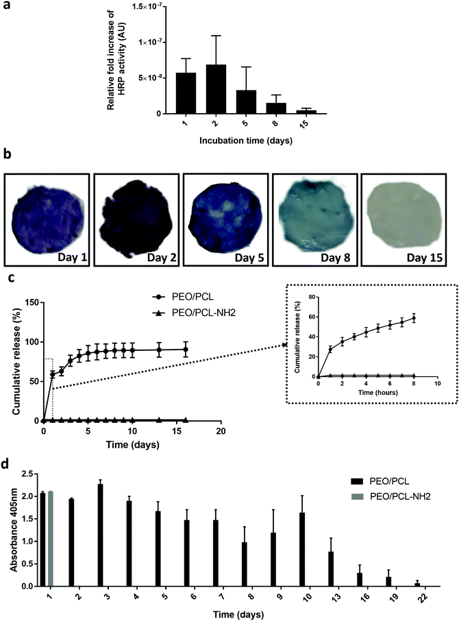
Fig. 5c shows a burst release of the loaded HRPCM of 60% within the first hour. Then 30% was released in the following three hours. The ABTS assay (Fig. 5d), showed that the released protein was active after 48 h of release. These experiments indicated that the mixed functional fibre system coaxial electrospun PEO/PCL/JFA fibres allowed the simultaneous release of protein from the core of the fibres and the immobilisation of another protein, with retention of activity, on the same scaffold.
3.6 Scaffold cytocompatibility and biological response
The cellular responses to PEO/PCL/JFA scaffolds with biological molecules incorporated were evaluated with respect to cell attachment and albumin secretion by HepG2 cells.4. Conclusion
In conclusion, aminolyzed PEO/PCL and PEO/PCL/JFA electrospun scaffolds were successfully fabricated and characterised. We showed that the use of JFA in a coaxial electrospun scaffold, facilitates the production of a multiple protein delivery fibrous system. In contrast, aminolysis treatment, which is considered as the gold standard for surface functionalisation, was suitable for the surface functionalisation of the scaffolds but was not suitable when a bioactive was loaded in the core due to loss of the bioactivity during aminolysis. We conclude here therefore that the use of JFA does not affect the stability of a pre-loaded protein in the core enabling the simultaneous incorporation of multiple proteins in the same scaffold without affecting their activity. Additionally, surface analysis and mechanical characterisation showed that JFA rendered the scaffold more elastic than PEO/PCL fibres alone. Finally, the biocompatibility of surface functionalisation of the PEO/PCL/JFA fibre scaffolds was confirmed, and modulation of cellular responses to the incorporated bioactive molecules were successfully demonstrated.34,35Conflicts of interest
There are no conflicts to declare.Acknowledgements
This work was supported by the Engineering and Physical Sciences Research Council (EPSRC) and Medical Research Council (MRC) Centre for Doctoral Training in Regenerative Medicine (EP/L015072/1) doctoral training grant awarded to IA. We would like to thank Ms Denise McLean and Ms Emily Smith from the University of Nottingham Nanoscale and Microscale Research Centre (nmRC) for their help with TEM and XPS respectively.References
- R. Censi, P. Di Martino, T. Vermonden and W. E. Hennink, Hydrogels for Protein Delivery in Tissue Engineering, J. Controlled Release, 2012, 161, 680–692 CrossRef CAS PubMed.
- M. Okamoto, Handbook of Tissue Engineering Scaffolds, 2019, vol. 1 Search PubMed.
- B. P. Chan and K. W. Leong, Scaffolding in Tissue Engineering: General Approaches and Tissue-Specific Considerations, Eur. Spine J., 2008, 17(suppl 4), 467–479 CrossRef PubMed.
- X. Gao, S. Han, R. Zhang, G. Liu and J. Wu, Progress in Electrospun Composite Nanofibers: Composition, Performance and Applications for Tissue Engineering, J. Mater. Chem. B, 2019, 7, 7075–7089 RSC.
- P. Rebulla and L. Lecchi, Towards Responsible Cord Blood Banking Models, Cell Proliferation, 2011, 44(suppl 1), 30–34 CrossRef PubMed.
- M. R. Battig, B. Soontornworajit and Y. Wang, Programmable Release of Multiple Protein Drugs from Aptamer-Functionalized Hydrogels Via Nucleic Acid Hybridization, J. Am. Chem. Soc., 2012, 134, 12410–12413 CrossRef CAS PubMed.
- S. Kobsa and W. M. Saltzman, Bioengineering Approaches to Controlled Protein Delivery, Pediatr. Res., 2008, 63(5), 513–519 CrossRef PubMed.
- N. Bhardwaj and S. C. Kundu, Electrospinning: A Fascinating Fiber Fabrication Technique, Biotechnol. Adv., 2010, 28, 325–347 CrossRef CAS PubMed.
- Y. Li, F. Chen, J. Nie and D. Yang, Electrospun Poly(Lactic Acid)/Chitosan Core-Shell Structure Nanofibers from Homogeneous Solution, Carbohydr. Polym., 2012, 90, 1445–1451 CrossRef CAS PubMed.
- S. Agarwal, J. H. Wendorff and A. Greiner, Use of Electrospinning Technique for Biomedical Applications, Polymer, 2008, 49, 5603–5621 CrossRef CAS.
- T. T. T. Nguyen, O. H. Chung and J. S. Park, Coaxial Electrospun Poly(Lactic Acid)/Chitosan (Core/Shell) Composite Nanofibers and Their Antibacterial Activity, Carbohydr. Polym., 2011, 86, 1799–1806 CrossRef CAS.
- R. A. Perez and H. W. Kim, Core-Shell Designed Scaffolds for Drug Delivery and Tissue Engineering, Acta Biomater., 2015, 21, 2–19 CrossRef CAS PubMed.
- D. Han and A. J. Steckl, Coaxial Electrospinning Formation of Complex Polymer Fibers and Their Applications, ChemPlusChem, 2019, 84, 1453–1497 CrossRef CAS PubMed.
- H. Jiang, L. Wang and K. Zhu, Coaxial Electrospinning for Encapsulation and Controlled Release of Fragile Water-Soluble Bioactive Agents, J. Controlled Release, 2014, 193, 296–303 CrossRef CAS PubMed.
- G. S. Schultz and A. Wysocki, Interactions between Extracellular Matrix and Growth Factors in Wound Healing, Wound Repair Regen., 2009, 17, 153–162 CrossRef PubMed.
- A. C. B. Allen, E. Barone, C. O. K. Crosby, L. J. Suggs and J. Zoldan, Electrospun Poly(N-Isopropyl Acrylamide)/Poly(Caprolactone) Fibers for the Generation of Anisotropic Cell Sheets, Biomater. Sci., 2017, 5, 1661–1669 RSC.
- M. Cobos, J. R. Ramos, D. J. Guzman, M. D. Fernandez and M. J. Fernandez, Pcl/Poss Nanocomposites: Effect of Poss Derivative and Preparation Method on Morphology and Properties, Polymers, 2018, 11 Search PubMed.
- I. Aldalur, H. Zhang, M. Piszcz, U. Oteo, L. M. Rodriguez-Martinez, D. Shanmukaraj, T. Rojo and M. Armand, Jeffamine® Based Polymers as Highly Conductive Polymer Electrolytes and Cathode Binder Materials for Battery Application, J. Power Sources, 2017, 347, 37–46 CrossRef CAS.
- L. Mascia, R. Su, J. Clarke, Y. Lou and E. Mele, Fibres from Blends of Epoxidized Natural Rubber and Polylactic Acid by the Electrospinning Process: Compatibilization and Surface Texture, Eur. Polym. J., 2017, 87, 241–254 CrossRef CAS.
- M. Ignatova, N. Stoyanova, N. Manolova, I. Rashkov, R. Kukeva, R. Stoyanova, R. Toshkova and A. Georgieva, Electrospun Materials from Polylactide and Schiff Base Derivative of Jeffamine Ed(R) and 8-Hydroxyquinoline-2-Carboxaldehyde and Its Complex with Cu(2+): Preparation, Antioxidant and Antitumor Activities, Mater. Sci. Eng., C, 2020, 116, 111185 CrossRef CAS PubMed.
- U. Stachewicz, C. A. Stone, C. R. Willis and A. H. Barber, Charge Assisted Tailoring of Chemical Functionality at Electrospun Nanofiber Surfaces, J. Mater. Chem., 2012, 22, 22935 RSC.
- F. Causa, E. Battista, R. Della Moglie, D. Guarnieri, M. Iannone and P. A. Netti, Surface Investigation on Biomimetic Materials to Control Cell Adhesion: The Case of Rgd Conjugation on Pcl, Langmuir, 2010, 26, 9875–9884 CrossRef CAS PubMed.
- S. Regis, S. Youssefian, M. Jassal, M. D. Phaneuf, N. Rahbar and S. Bhowmick, Fibronectin Adsorption on Functionalized Electrospun Polycaprolactone Scaffolds: Experimental and Molecular Dynamics Studies, J. Biomed. Mater. Res., Part A, 2014, 102, 1697–1706 CrossRef PubMed.
- J. Schindelin, et al., Fiji: An Open-Source Platform for Biological-Image Analysis, Nat. Methods, 2012, 9, 676–682 CrossRef CAS PubMed.
- S. B. Qasim, S. Najeeb, R. M. Delaine-Smith, A. Rawlinson and I. Ur Rehman, Potential of Electrospun Chitosan Fibers as a Surface Layer in Functionally Graded Gtr Membrane for Periodontal Regeneration, Dent. Mater., 2017, 33, 71–83 CrossRef CAS PubMed.
- D. Fernandez, M. Guerra, J. G. Lisoni, T. Hoffmann, R. Araya-Hermosilla, T. Shibue, H. Nishide, I. Moreno-Villoslada and M. E. Flores, Fibrous Materials Made of Poly(Epsilon-Caprolactone)/Poly(Ethylene Oxide)-B-Poly(Epsilon-Caprolactone) Blends Support Neural Stem Cells Differentiation, Polymers, 2019, 11, 1621, DOI:10.3390/polym11101621.
- M. Rubert, J. Dehli, Y.-F. Li, M. B. Taskin, R. Xu, F. Besenbacher and M. Chen, Electrospun Pcl/Peo Coaxial Fibers for Basic Fibroblast Growth Factor Delivery, J. Mater. Chem. B, 2014, 2, 8538–8546 RSC.
- R. Nayak, R. Padhye, I. L. Kyratzis, Y. B. Truong and L. Arnold, Effect of Viscosity and Electrical Conductivity on the Morphology and Fiber Diameter in Melt Electrospinning of Polypropylene, Text. Res. J., 2012, 83, 606–617 CrossRef.
- R. Dwivedi, S. Kumar, R. Pandey, A. Mahajan, D. Nandana, D. S. Katti and D. Mehrotra, Polycaprolactone as Biomaterial for Bone Scaffolds: Review of Literature, J. Oral Biol. Craniofac. Res., 2020, 10, 381–388 CrossRef PubMed.
- Y. He, R. D. Wildman, C. J. Tuck, S. D. Christie and S. Edmondson, An Investigation of the Behavior of Solvent Based Polycaprolactone Ink for Material Jetting, Sci. Rep., 2016, 6, 20852 CrossRef CAS PubMed.
- T. Haddad, S. Noel, B. Liberelle, R. El Ayoubi, A. Ajji and G. De Crescenzo, Fabrication and Surface Modification of Poly Lactic Acid (Pla) Scaffolds with Epidermal Growth Factor for Neural Tissue Engineering, Biomatter, 2016, 6, e1231276 CrossRef PubMed.
- J. E. Koblinski, M. Wu, B. Demeler, K. Jacob and H. K. Kleinman, Matrix Cell Adhesion Activation by Non-Adhesion Proteins, J. Cell Sci., 2005, 118, 2965–2974 CrossRef CAS PubMed.
- R. Michelle and C. M. R. Burley, Effects of Retinoic Acid on Proliferation and Differentiation of Hepg2, Open Biotechnol. J., 2007, 1, 47–51 CrossRef.
- S. Chen, J. V. John, A. McCarthy and J. Xie, New Forms of Electrospun Nanofiber Materials for Biomedical Applications, J. Mater. Chem. B, 2020, 8, 3733–3746 RSC.
- F. F. R. Damanik, G. Spadolini, J. Rotmans, S. Fare and L. Moroni, Biological Activity of Human Mesenchymal Stromal Cells on Polymeric Electrospun Scaffolds, Biomater. Sci., 2019, 7, 1088–1100 RSC.
Footnote |
| † Electronic supplementary information (ESI) available. See DOI: 10.1039/d1tb00129a |
| This journal is © The Royal Society of Chemistry 2021 |

