Layered electrode materials for non-aqueous multivalent metal batteries

Ahiud Morag and Minghao Yu *
Center for Advancing Electronics Dresden (cfaed) & Faculty of Chemistry and Food Chemistry, Technische Universität Dresden, Mommsenstrasse 4, 01062 Dresden, Germany. E-mail: minghao.yu@tu-dresden.de

Received 6th May 2021 , Accepted 9th July 2021

First published on 15th July 2021


Abstract

The global transition to clean energy production accelerates the necessity for efficient energy storage solutions. Lithium-ion batteries (LIBs), developed considerably over the past three decades, have been widely applied in portable electronics and electric vehicles. Nevertheless, the application of LIBs in large-scale energy storage applications is restricted by the Li resource scarcity, high-cost raw materials, and severe safety issues, which thus triggers the development of new battery chemistries beyond Li+. In this regard, multivalent metal batteries (MVMBs, e.g., Zn, Mg, and Al batteries) are promising alternatives owing to the advantages brought by the direct use of corresponding metals as anodes, such as high elemental abundance, low anode redox potential, multielectron redox capability, and facile metal stripping and plating chemistry. However, MVMBs suffer from the lack of available cathodes for efficiently accommodating multivalent metal ions (i.e., Zn2+, Mg2+, and Al3+), which originates from the strong electrostatic interactions between charge carrier ions and cathodes. Promising cathode candidates for MVMBs to address this challenge are layered electrode materials, whose structures can be engineered with versatile approaches to regulate the charge-storage behaviour. Here, layered electrode materials used for non-aqueous MVMB cathodes are thoroughly reviewed. We first introduce the cell configurations and the thus-far developed anode–electrolyte–cathode chemistries for non-aqueous MVMBs. Recent progress in the exploration of layered materials for non-aqueous MVMBs is subsequently summarized. Emphasis is put on examining the employed structure engineering strategies and their effects on both the intrinsic properties and electrochemical behaviours of layered electrode materials. Finally, perspectives on the challenges and future directions in this research field are provided with aspects to the cathode structure engineering, performance assessment, and device demonstration.
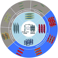

image file: d1ta03842g-p1.tif

Ahiud Morag

Ahiud Morag received his PhD degree in interdisciplinary studies from Ben Gurion University of the Negev, Israel, in June 2019. In October 2019, he joined Prof Xinliang Feng's group at Technische Universität Dresden (TU Dresden) as a postdoctoral research associate. His research mainly focuses on the development of novel cathodes and electrolytes for non-aqueous magnesium and aluminum multivalent metal batteries.

image file: d1ta03842g-p2.tif

Minghao Yu

Minghao Yu received his PhD degree in Material Physics and Chemistry from Sun Yat-sen University in June 2017. In March 2019, he became a research group leader of the Chair for Molecular Functional Materials at Technische Universität Dresden. His research interests focus on the development of advanced functional materials for applications of energy storage (supercapacitors and metal-ion batteries) and conversion (electrocatalysis and metal-air batteries).


1. Introduction

Global warming is pushing towards the transition from traditional fossil fuels to clean energy resources like solar, wind, and tidal energies.1,2 However, the intermittent nature of these clean and cheap energy resources restricts their direct utilization, which imposes a strong demand for high-performance energy storage technologies.3–5 Among existing electrochemical energy storage technologies, lithium-ion batteries (LIBs) represent the most commercially successful one, and they have been implemented in diverse applications, such as portable electronics and electric vehicles.6,7 However, the severe safety issues of LIBs, limited Li resource in the earth crust (20 ppm, 0.002%), and the increasing demand for cheap energy storage solutions motivate the development of new battery chemistries relying on cheap and abundant elements. In this context, multivalent metal batteries (MVMBs) are proposed as promising alternatives, which directly employ resource-abundant and low-cost multivalent metals (e.g., Zn, Mg, and Al) as anodes.8–16 Typically, multivalent metal anodes present low stripping/plating potentials (−0.76, −2.37, and −1.66 V vs. standard hydrogen electrode (SHE) for Zn, Mg, and Al, respectively), which are beneficial for the construction of high-voltage and high-energy energy storage devices (Fig. 1). Importantly, Zn, Mg, and Al are the 24th, 8th, and 3rd most abundant elements in the Earth's crust, respectively. These metal anodes can deliver high specific capacities due to their multielectron redox capability (820, 2206, and 2981 mA h g−1 for Zn, Mg, and Al, respectively). Meanwhile, the high mass densities of multivalent metals empower the corresponding anodes with impressive volumetric capacities (5849, 3834, and 8047 Ah L−1 for Zn, Mg, and Al, respectively). Interestingly, the partial compatibility of multivalent metals (especially Zn) with water-based electrolytes inspired researchers to develop aqueous MVMBs. Aqueous electrolytes enable the fabrication of low-cost and safe MVMBs with fast cation-storage kinetics of the cathodes.17,18 However, aqueous MVMBs suffer from low voltage windows (normally less than 1.8 V) due to the narrow stable potential windows of water-based electrolytes. Moreover, water in electrolytes would lead to the formation of passivation layers on metal anodes, which can inhibit the stripping/plating of Mg and Al and accelerate the dendrite growth of Zn. By contrast, multivalent metals show negligible passivation or dendrite growth in non-aqueous electrolytes, providing the metal stripping/plating process with high coulombic efficiency.19–24 Additionally, non-aqueous electrolyte displays substantially higher potential window than aqueous electrolytes, enabling the use of many cathode materials with high redox potentials. All these features allow non-aqueous MVMBs to be promising candidates to abreast with LIBs as leading energy storage technologies.
image file: d1ta03842g-f1.tif
Fig. 1 Specific capacities, volumetric capacities, ionic radii, and stripping/plating potentials of various metal ions.

However, the construction of practical non-aqueous MVMBs is hindered by severe challenges induced by the multivalent metal ions as charge carriers for cathodes. Multivalent metal ions display large charge densities, resulting from the multivalent nature and the small ionic radii (0.74, 0.72, and 0.53 Å for Zn2+, Mg2+, and Al3+ compared with 0.76 Å for Li+). It further leads to the strong electrostatic interactions between charge carrier ions and cathodes during the charge/discharge of non-aqueous MVMBs. Consequently, most well-recognized metal oxide cathodes for LIBs stand inappropriate for non-aqueous MVMB cathodes.25–31 In this sense, cathode structures for non-aqueous MVMBs should be re-designed at the atomic level to enable facile Zn2+, Mg2+, and Al3+ storage.

As promising cathode candidates for non-aqueous MVMBs, natural layered materials are a class of materials with strong atom bonding in the basal plane and weak van der Waals (vdW) interaction between layers. These materials are equipped with versatile physical, chemical, electronic properties, as well as broad structural diversity.32–35 Particularly, layered materials are appealing for energy storage, as they exhibit some intrinsic advantages over non-layered materials. For example, compared with non-layered materials, layered materials depicted higher accessibility of exposed active sites, enabling higher specific capacities and better ion diffusion kinetics.36–38 However, some layered materials suffer from phase transition during electrochemical processes and poor stability in the ambient environment.39 Thus far, a variety of layered materials have been explored as cathodes for MVMBs, including layered transition metal oxides (TMOs),32,40 transition metal dichalcogenides (TMDs),41–43 graphite,44,45 and two-dimensional (2D) covalent organic frameworks (COFs).46 Pristine layered materials as non-aqueous MVMB cathodes generally exhibit limited electrochemical performance.47 Importantly, the weak vdW interaction between the stacked layers enables layered materials with diverse possibilities for rational structure engineering, such as exfoliation into 2D nanoflakes, interlayer expansion with guest molecules, and hybrid structure construction (Fig. 2).48 These structure engineering strategies are highly desired for layered materials to tailor their intrinsic properties (e.g., electronic structure, conductivity, and redox capability) and electrochemical behaviours (e.g., ion desolvation energy, solid-state ion diffusion kinetics, charge-storage mechanism) for multivalent metal ion storage.


image file: d1ta03842g-f2.tif
Fig. 2 Schematic illustration of the review content, including the cell configuration of non-aqueous MVMBs, layered cathode materials, and structure engineering methods.

In this review, the latest development of layered materials for non-aqueous MVMB cathodes is reviewed. We first summarize the typical configurations of non-aqueous MVMBs in terms of the developed electrolytes, typical anode–electrolyte–cathode chemistries, and possible charge carrier ions. Next, a comprehensive overview of state-of-the-art layered materials used for non-aqueous MVMBs is carried out by emphasizing the strategies applied to tailor the structures of layered materials. Emphatic efforts are devoted to analysing the induced changes in the intrinsic properties and electrochemical behaviours of layered materials upon the structure regulation. Finally, perspectives on the current challenges and future directions of layered materials for non-aqueous MVMBs are presented.

2. Cell configurations of non-aqueous MVMBs

Contrasting to Li-metal anodes, Zn-, Mg-, and Al-metal anodes can be easily processed and show no aggressive dendrite growth in non-aqueous electrolytes during battery operation.49 Although multivalent metals can be directly used as anodes, their stripping/plating reactions are not the simple Mx+ + xe → M reaction. Exact reaction mechanisms on multivalent metal anodes are introduced in this section. Additionally, according to the different cathode chemistry, non-aqueous MVMBs can be briefly categorized into cation ‘rocking-chair’ cells and dual-ion cells. In ‘rocking-chair’ cells, cation released from cathodes and metal plating on anodes occur during the charge of cells, while cation storage in cathodes and metal stripping on anodes occur during the discharge of cells. The electrolyte concentration in the ‘rocking-chair’ cells keeps constant during the cell operation. In dual-ion cells, anions serve as charge carrier ions for cathodes, which are stored/released in/from cathodes during the charge/discharge process of cells. The charge process would consume ions in electrolytes, and high-concentration or large amounts of electrolytes are preferred for dual-ion cells.50 In this section, we also discuss the cathode chemistries of MVMBs with a particular focus on the different charge carrier species.

2.1 Zn-metal batteries

The Zn2+/Zn couple has a sufficiently high redox potential of −0.76 V vs. SHE, which enables the Zn stripping/plating reaction to be feasible in either alkaline or close-to-neutral aqueous electrolytes. Moreover, the use of water-based electrolytes brings the advantages of low cost, high safety, high ionic conductivity, and easy-to-manufacture feature.51 Thereby, dominant researches of Zn-metal batteries (ZMBs) are focused on aqueous systems. Aqueous ZMBs are not covered in this review, and interested readers are directed to recent comprehensive reviews of this field.52–57 It is worth noting that aqueous ZMBs are restricted by several intrinsic drawbacks arising from the use of aqueous electrolytes. Cathode materials like MnO2 and VOPO4 suffer from dissolution in water, resulting in fast capacity degradation during cycling.58,59 Additionally, Zn-metal anodes in aqueous electrolytes exhibit severe side reactions (e.g., hydrogen evolution, ZnO formation) and Zn dendrite growth, which further lead to the electrolyte decomposition, irreversible Zn consumption, low stripping/plating coulombic efficiency, and safety issues.60

Non-aqueous electrolytes based on ionic liquid, acetonitrile (AN) or carbonate solvents with Zn salts (e.g., zinc bis(trifluoromethylsulfonyl)imide (Zn(TFSI)2), Zn(CF3SO3)2 (Zn(OTf)2), Zn(ClO4)2, Zn(BF4)2, and Zn(PF6)2) were demonstrated feasible for reversible Zn stripping and plating.24,61–66 These electrolytes offer much wider voltage windows than aqueous electrolytes. For example, Han et al.64 showed that both AN and propylene carbonate (PC), dissolving different Zn salts (e.g., Zn(TFSI)2, Zn(OTf)2, Zn(BF4)2, and Zn(PF6)2), demonstrated high anodic stability of 3.8 V vs. Zn2+/Zn. Wang et al.24 developed a Li+-containing hybrid electrolyte, exhibiting high anodic stability of 4 V vs. Zn2+/Zn. The high anodic stability was achieved by adding LiPF6 to Zn(TFSI)2 in ethyl methyl carbonate (EMC). The wide voltage windows of non-aqueous Zn electrolytes are crucial for the fabrication of high-voltage and high-energy ZMBs.

According to the cathode chemistries, two possible charge storage mechanisms for non-aqueous ZMBs are presented in Fig. 3. The first one relies on the Zn2+ ‘rocking-chair’ mechanism. The high energy barrier of Zn2+ desolvation on the cathode surface accounts for the large charge-transfer resistance of these ZMBs.61,66,67 The second mechanism is based on dual-ion cells, involving Zn plating/stripping on the anode and anion storage/release on the cathode. The charge-transfer resistance of anion storage is considerably lower than that of Zn2+ storage, enabling the excellent rate performance of ZMBs.24,68 So far, several cathode materials with the Zn2+-storage mechanism were reported for non-aqueous ZMBs, including MnO2,66 vanadium oxide,61,65 and VOPO4.69 On the other hand, graphite-based cathodes, exhibiting anion intercalation/de-intercalation, were used for constructing dual-ion ZMBs.23,24,68 Anions, such as PF6, TFSI, and OTf can be used as charge carriers for cathodes, providing ZMBs with high operation voltages and high energy densities. Overall, compared with aqueous ZMBs, non-aqueous ZMBs benefit from high anodic stability and dendrite-free Zn stripping and plating.


image file: d1ta03842g-f3.tif
Fig. 3 Schematic illustration showing the charge storage mechanism of ZMBs.

2.2 Mg-metal batteries

The Mg metal surface would be passivated in most solvents by an Mg2+ non-conducting layer, preventing the electrochemical Mg plating. In detail, electrolytes comprised of conventional solvents and Mg salts, such as Mg(TFSI)2 or Mg(ClO4)2 in AN or carbonate solvents, are not suitable for Mg-metal batteries (MMBs),70 because these electrolytes tend to form ionic-insulating passivation layers (e.g., MgO, MgCl2, and MgxClOy) on Mg metal. Grignard reagents (e.g., EtMgBr, and Mg(BR4)2, where R = butyl, phenyl) dissolved in ethers were presented as the first suitable electrolytes for the facile Mg stripping/plating.70–72 However, Grignard reagent-based electrolytes show low anodic stability (<1.5 V vs. Mg2+/Mg).72,73 In 2000, Aurbach with his colleagues reported the MMB electrolyte, Mg(AlCl2BuEt)2, with high anodic stability.74 The electrolyte was prepared by mixing MgR2 (R is butyl or ethyl) and AlCl2R/AlCl3 in tetrahydrofuran (THF). The reaction between RMgCl and RxAlCl3−x produced RxAlCl4−x and active Mg-containing cations (e.g., MgCl+ and Mg2Cl3+).75–78 Importantly, the Mg(AlCl2BuEt)2 electrolyte exhibited a large electrochemical window of 2.5 V vs. Mg2+/Mg, superior to electrolytes without the addition of AlCl3 (e.g., Mg(BPh2Bu2)2 and BuMgCl). Moreover, all phenyl complex (APC) electrolytes, the most commonly used electrolytes for MMBs, can be obtained by substituting the alkyl group of RMgCl with the phenyl group. These APC electrolytes can demonstrate wide stable potential windows of more than 3 V vs. Mg2+/Mg.79 Recent studies revealed that reducing the RxAlCl4−x concentration and increasing the AlCl4 concentration further improved the anodic stability of electrolytes. The low HOMO level of AlCl4 played an important role in improving the potential window. Zhao et al.80 further improved the anodic stability of APC electrolytes by adding 1-butyl-1-methylpiperidinium chloride (PP14Cl). The Cl ions reacted with RxAlCl4−x to produce AlCl4, consequently increasing the anodic stability from 2.9 to 3.1 V vs. Mg2+/Mg.

Magnesium aluminium chloride complex (MACC) dissolved in ether solvents (e.g., dimethoxyethane (DME)) represents an important type of MMB electrolytes with all-inorganic salts (e.g., AlCl3 and MgCl2).81–83 During the preparation of MACC electrolytes, different acid–base reactions occur depending on the ratio between AlCl3 and MgCl2. For MgCl2[thin space (1/6-em)]:[thin space (1/6-em)]AlCl3 ratio of 2[thin space (1/6-em)]:[thin space (1/6-em)]1 and 1[thin space (1/6-em)]:[thin space (1/6-em)]1, the dominating MgxCly2xy species in the electrolyte are Mg2Cl3+ and MgCl+ through eqn (1) and (2). In these cases, Mg undergoes facile electrochemical stripping and plating due to the presence of MgxCly2xy species. Increasing the MgCl2[thin space (1/6-em)]:[thin space (1/6-em)]AlCl3 ratio to 1[thin space (1/6-em)]:[thin space (1/6-em)]2 inhibits Mg plating due to the low concentration of MgxCly2xy species.82 Moreover, when the AlCl3[thin space (1/6-em)]:[thin space (1/6-em)]MgCl2 ratio is higher than 2[thin space (1/6-em)]:[thin space (1/6-em)]1, the formation of AlCl2+ would cause severe Mg metal corrosion.84 Typical MACC electrolytes require the pre-cycling process to reduce the overpotential and improve the electrochemical stripping/plating coulombic efficiency.85 The pre-cycling process is termed conditioning, and would complicate the production of MMBs. Conditioning-free MACC electrolytes can be obtained by adding additional salts like Mg(TFSI)2 and Mg(hexamethyldisilazide)2 (Mg(HMDS)2).84,86 Besides, these Mg-salt additives can improve the water-resistance of MACC electrolytes, allowing excellent Mg plating at a water content of 2000 ppm. Electrochemical Mg plating is also feasible by completely replacing AlCl3 in MACC electrolytes with either Mg(TFSI)2 or Mg(HMDS)2.87,88 In the MgCl2/Mg(TFSI)2 electrolyte, salts and solvents must have high purity by removing water residue to realize the facile Mg stripping and plating. By contrast, purification is not necessary for the Mg(HMDS)2/MgCl2 electrolyte to achieve reversible Mg stripping and plating.

 
AlCl3 + 2MgCl2 → AlCl4 + Mg2Cl3+(1)
 
AlCl3 + MgCl2 → AlCl4 + MgCl+(2)

Chloride presence in MMB electrolytes accounts for the corrosive nature of electrolytes for common current collectors (e.g., Al and stainless steel), thus encouraging the development of chlorine-free Mg electrolytes. Mohtadi et al.90 presented a chlorine-free electrolyte based on Mg(BH4)2 in DME. Nevertheless, the electrolyte displayed low coulombic efficiency (67%), and the decomposition of BH4 lead to the low anodic stability (2.3 V vs. Mg2+/Mg) of the electrolyte. Inspired by Mohtadi's work, Tutusaus and co-workers91 reported a halogen-free electrolyte with dodecaborate dianions for successful Mg stripping and plating. Impressively, the electrolyte demonstrated outstanding anodic stability of 3.8 V vs. Mg2+/Mg.91 Following this strategy, Luo et al.89 synthesized Mg perfluorinated pinacolatoborate (FPB) for MMB electrolytes, which depicted outstanding anodic stability of 4.0 V vs. Mg2+/Mg. However, it should be pointed out that the synthesis of boron-based Mg salts generally requires harsh conditions under inert environments. Complicated synthetic routes impose a potential risk for the practical application of these boron-based electrolytes. A summary of the main features of developed Mg electrolytes is presented in Table 1.

Table 1 Comparison of developed MMB electrolytes
Electrolyte name APC79 Mg-HMDS88 MACC81,82 Mg(BRn)2 (ref. 89)
Main precursors PhMgCl, AlCl3 Mg(HMDS)2, MgCl2 MgCl2, AlCl3 Mg(BH4)2, C6H2F12O2
Cations and anions image file: d1ta03842g-u1.tifMgxCly+ and PhxAlCl4−x image file: d1ta03842g-u2.tifMg2Cl3+ and HMDSAlCl3 image file: d1ta03842g-u3.tifMg2Cl3+ and AlCl4 image file: d1ta03842g-u4.tifMg2+ and B(O2C2(CF3)4)2
Anodic stability 2.5 V vs. Mg2+/Mg 2.8 V vs. Mg2+/Mg 3.5 V vs. Mg2+/Mg 4.0 V vs. Mg2+/Mg
Coulombic efficiency ∼100% 99% 99% 95%
Advantages High coulombic efficiency Good cathode compatibility Simple synthesis, high concentration High anodic stability
Drawbacks Low anodic stability Low anodic stability Conditioning required Complicated synthetic process


With the demonstrated anode–electrolyte chemistries, searching compatible cathodes represents the main task to establish suitable full-device chemistries. The large charge density of Mg2+ and its strong binding to Cl and solvent molecules rule out many recognized cathode materials in other battery systems. The first demonstrated MMB cathode with decent performance is the Chevrel-phase Mo6S8.74 Theoretical studies suggest that the Chevrel phase surface can significantly accelerate the desolvation and dissociation of Mg2Cl3+ in THF, reducing the dissociation energy of Mg2Cl3+ from 3.0 eV to 0.2 eV.92 For this reason, the Chevrel phase is one of a few inorganic materials that can be used as cathodes of MMBs without structure modification or special conditions (e.g., elevated temperature).

Besides, TMOs are considered promising materials for energy storage due to their high theoretical capacities and operation potentials. Apart from classic Mg2+ intercalation, TMO can also store charge through the conversion mechanism. The charge storage mechanism is determined by the type of TMOs and the nature of electrolytes.93–95 However, TMO cathodes for MMBs suffer from large voltage hysteresis and sluggish intercalation kinetics. These issues can be assigned to the strong electrostatic interactions between O atoms in TMOs and Mg2+.96 In addition, the compatibility of TMOs with chloride-containing electrolytes is poor, making the fabrication of MMBs with TMO cathodes a great challenge.94 Another class of MMB cathodes is TMDs, which display better Mg2+-intercalation kinetics than TMOs in light of the weak electrostatic interactions between chalcogenide atoms and Mg2+. Unlike TMOs, TMDs are compatible with chloride-containing electrolytes. However, the main issue associated with TMDs is their much lower theoretical capacities and redox potentials than those of TMOs. The charge storage mechanism was shown to be either intercalation reaction or intercalation/conversion reaction with Mg2+, MgCl+, or [Mg(DME)3]2+ as charge-carrier species (Fig. 4).


image file: d1ta03842g-f4.tif
Fig. 4 Schematic illustration showing the charge storage mechanism of MMBs.

2.3 Al-metal batteries

Trivalent Al3+ and the high abundance of Al resources make Al-metal batteries (AMBs) to be promising candidates for large-scale energy storage. However, electrochemical Al stripping and plating is challenging in both organic and ionic liquid electrolytes. The large charge density of Al3+ induces the strong coulombic anion–cation interactions in Al salts (e.g., Al(TFSI)3 and Al(OTf)3), which further results in the low solubility of Al salts in common carbonate solvents. On the other hand, although ether-based solvents (e.g., DME and diglyme) can dissolve Al salts, these solvents exhibit strong interactions with cations, leading to high solvation energies.97,98 To achieve facile Al stripping/plating, the commonly used chemistry takes use of Al2X7 (X is Cl or Br), as shown in eqn (3).99–102 The Al plating chemistry was first discovered in high-temperature (140–180 °C) molten salts, such as AlCl3–LiCl and AlCl3–NaCl–KCl.100,101 However, the requirement of high temperature would greatly restrict the practical application of AMBs in energy storage devices. To this end, room-temperature ionic liquids with low viscosity are employed for AMBs. The most commonly used ionic liquids are mixtures of AlCl3 and 1-ethyl-3-methylimidazolium chloride (EMIMCl). To achieve Al plating, the AlCl3[thin space (1/6-em)]:[thin space (1/6-em)]EMIMCl molar ratio should be higher than 1 to ensure the presence of Al2Cl7 through the reactions of eqn (4) and (5). The standard reduction potential of Al2Cl7 is −0.7 V vs. SHE (eqn (3)), which is almost 1.0 V higher than the direct reduction of Al3+ (−1.66 V vs. SHE).103
 
4Al2X7 + 3e ↔ Al + 7AlX4(3)
 
AlCl3 + EMIMCl ↔ AlCl4 + EMIM+(4)
 
AlCl3 + AlCl4 ↔ Al2Cl7(5)

Besides, mixtures of AlCl3 with amides (e.g., urea and acetamide) can serve as economical alternatives for ionic liquid-based electrolytes.104,105 In these cases, AlCl4, Al2Cl7, and AlCl2+ are formed through the reactions in eqn (5) and (6). Thermodynamically, Al plating can also be achieved through the reduction of AlCl2+. However, calculations showed that the large energy barrier associated with the dissociation of Al-amide bonds restricted this reaction (Fig. 5).104 This fact could explain why electrochemical Al striping/plating occurs only with the presence of Al2Cl7. While amide/AlCl3-based electrolytes are appealing for replacing ionic liquid-based electrolytes from a cost perspective, they suffer from high viscosity and low ionic conductivity. These drawbacks result in the inferior performance of AMBs with amide/AlCl3 electrolytes, compared with AMBs with EMIMCl/AlCl3 electrolytes.105

 
2AlCl3 + 2urea ↔ AlCl4 + AlCl2(urea)2+(6)


image file: d1ta03842g-f5.tif
Fig. 5 Energy profiles of the dissociation reactions of (a) Al2Cl7 and (b) [AlCl2(acetamide)2]+. Reprinted with permission from ref. 104. Copyright 2018 Elsevier.

Intercalation of large-charge-density Al3+ usually leads AMB cathodes to poor cyclability and low-rate capability. For example, inorganic cathode materials (e.g., TiO2,29 TiS2,106 Co9S8,107 and V2O5 (ref. 108)), with charge storage involving Al3+, demonstrate significant capacity fading during the first few cycles. In addition to the sluggish Al3+ intercalation, the high dissociation energy of Al2Cl7 to Al3+ (eqn (7)) is another important reason for the low rate capability and large charge/discharge voltage hysteresis of AMBs with Al3+ storage. Recently, Yang et al.109 reported that the dissociation rate of Al2Cl6Br, prepared by mixing AlCl3 with EMIMBr, was 15-fold faster than that of Al2Cl7. However, the voltage window of this Al2Cl6Br-based electrolyte exhibited a narrow potential window, which was only suitable for low-potential cathodes, such as TiS2 (ref. 106) and TiO2.29 Other Al-based species, such as AlCl2+ and AlCl4, generally act as favourable charge carriers for AMB cathodes (Fig. 6).21,110,111 In detail, AlCl4 can serve as the charge carrier for graphite and amine compounds.21,112,113 On the other hand, n-type organic electrodes (e.g., pyrazine,114 polyaniline,115 and phenanthrenequinone110) can store charges through redox reactions with AlCl2+. Compared with Al3+, AlCl2+ as the charge carrier allows cathodes with higher charge/discharge rates and better cyclability. The intercalation of Al3+ was disclosed to be challenging in most materials, pushing towards the development of new n-type and p-type organic materials for AlCl2+/AlCl4 storage.

 
4Al2Cl7 → 4AlCl4 + 4AlCl3 → 7AlCl4 + Al3+(7)


image file: d1ta03842g-f6.tif
Fig. 6 Schematic illustration showing the charge storage mechanism of AMBs.

3. Layered cathode materials for MVMBs

Layered materials present 2D topologies with flat planes, forming a bulk structure through the weak vdW interaction. They have been widely used for both cation and anion storage due to their potentially high theoretical capacities and favourable 2D ion transport channels.41,44,46 Specifically, efficient cation/anion storage in layered materials can be promoted by large interlayer spacing, weak interactions between intercalating ions and host lattices, and the electronic conductivity of layered materials.116,117 Therefore, both intrinsic properties of layered materials and the applied structure modification have a prominent effect on the charge storage capability. In this section, we present the current state-of-the-art layered cathode materials used for non-aqueous MVMBs. The materials in this section are divided into four major groups, layered TMOs, TMDs, graphite-based materials, and 2D COFs. We analyse the proposed structure modification approaches and their influence on both the intrinsic physicochemical properties and the electrochemical performance enhancement of layered materials.

3.1 Layered transition metal oxides

TMOs include a broad class of materials with diverse structural frameworks, which exhibit excellent stability, environmental friendliness, and simple synthetic routes.117–120 The multiple valence states of transition metal elements arise from the coordination of the transition metal with highly electronegative oxygen, empowering TMOs with the superior charge storage capability (e.g., superior specific capacity). In addition, the high ionic feature of M–O bonds results in relatively high electrochemical redox potentials.37 However, the oxygen atoms of TMOs impose strong interactions with charge carrier ions (e.g., Zn2+, Mg2+, and Al3+), which leads to the limited ion-storage kinetics and poor structural stability of TMOs used in MVMBs.25,121 In this sense, layered TMOs allow solid-state ion diffusion through the 2D interlayer space, providing efficient ion transport pathways.122 Furthermore, structure modification of layered TMOs aims at weakening the interaction between intercalating ions and oxygen atoms. So far, several layered TMOs have been explored for MVMB cathodes, including manganese oxide, vanadium oxide, and vanadyl phosphate (VOPO4).
3.1.1 Manganese oxides. Manganese oxides have two layer-structure phases, namely, ε- and δ-phase MnO2. The δ-phase MnO2 (birnessite) is believed to provide more efficient pathways for cation diffusion than the ε-phase MnO2.123 Both MnO2 phases are composed of Mn4+ ions surrounded by six oxygen atoms, creating [MnO6] octahedral units. The [MnO6] units are linked via edge corners to form the layer structure.124–127 Birnessite MnO2 exhibits an interlayer distance of 7.24 Å, with a crystal water layer between two [MnO6] octahedral layers. It is promising battery cathode material in light of the high specific capacity (308 mA h g−1 for Mn3+/Mn4+ transition), nontoxicity, and low cost.

Due to the high specific capacity of MnO2,58 extensive researches have been conducted to use MnO2 as cathodes for aqueous ZMBs. Recently, Han et al.66 studied the charge storage performance of the δ-MnO2 cathode using Zn(TFSI)2 in AN as the electrolyte. δ-MnO2 was prepared by the reaction between KMnO4 and MnSO4, displaying a nanofloret-like morphology with an interlayer spacing of 7 Å. The Zn2+-intercalation mechanism of δ-MnO2 nanoflorets was studied using ex situ X-ray diffraction (XRD) and scanning transmission electron microscopy energy dispersive X-ray spectroscopy (STEM-EDS). After the first discharge, the (001) and (002) peak intensity of δ-MnO2 was significantly decreased, indicating the loss of long-range order in the layer direction. This was caused by the structural transformation of δ-MnO2 to the non-layered polymorph. The structural change caused the specific capacity increase to 123 mA h g−1 at 12.3 mA g−1 during the first 20 cycles. After 30 cycles, the specific capacity started to decay, reaching 55 mA h g−1 after 125 cycles. The decrease was attributed to the severe electrolyte decomposition and the formation of the passivation layer on the anode.

MnO2 was also studied as the cathodes of MMBs in light of its high redox potential vs. Mg2+/Mg. However, Mg2+ intercalation into layered MnO2 was not feasible with the electrolyte consisting of anhydrous Mg(ClO4)2 in AN.128 Therefore, the water-containing electrolyte was prepared using Mg(ClO4)2·xH2O with the H2O[thin space (1/6-em)]:[thin space (1/6-em)]Mg2+ ratio of 6. After the addition of water, Mg2+ intercalation was improved from a ratio of <0.2 Mg2+ per Mn for anhydrous Mg(ClO4)2 to a ratio of 0.7 Mg2+ per Mn (Fig. 7a). Interestingly, cycling with the water-containing electrolyte acted as an activation step of MnO2. The activated MnO2 maintained the good Mg2+-storage performance in the anhydrous electrolyte. The authors claimed that, during the discharge/charge cycling in the water-containing electrolyte, a slight structure re-orientation occurred, causing the activation of MnO2. However, due to the low crystallinity of the sample, the exact phase transition was not detected.


image file: d1ta03842g-f7.tif
Fig. 7 (a) Inductively coupled plasma-atomic emission spectroscopy Mg[thin space (1/6-em)]:[thin space (1/6-em)]Mn ratios of MnO2 nanowire electrodes discharged at −0.4 V vs. Ag/AgCl for 15 minutes in electrolytes with various H2O/Mg2+ ratios and expected Mg[thin space (1/6-em)]:[thin space (1/6-em)]Mn ratios which were calculated based on the total accumulated charges. Error bars indicate 95% confidence intervals. Reproduced from ref. 128 with permission from the PCCP Owner Societies. (b) Birnessite crystal structure showing a water monolayer between the MnO2 sheets. (c) The water content of the electrolyte as determined by Karl Fischer titration, showing the full water release after 20 cycles. (d) Cycling performance of MnO2·0.9H2O at C/10 and C/5. (e) Mn 2p3/2 XPS spectra of the pristine, discharged, and charged Mg-birnessite/carbon cloth electrodes; fits are shown in colour as labelled. Reprinted with permission from ref. 95. Copyright 2016 American Chemical Society.

To further understand the role of water in MnO2, Sun et al.95 investigated Mg2+ intercalation into Mg0.15MnO2·0.9H2O (Fig. 7b). Using Karl Fischer titration, it was disclosed that water molecules in the Mg0.15MnO2·0.9H2O structure were removed during the first 20 cycles. Remarkably, the first 20 cycles were also the cycles required for the full conditioning of the Mg0.15MnO2·0.9H2O cathode (Fig. 7c and d). The activation was also necessary for the water-containing electrolyte, suggesting that the activation is related to the structural change of Mg0.15MnO2·0.9H2O. X-ray photoelectron spectroscopy (XPS) measurements detected the exitance of MnOOH, MnO, and Mg(OH)2 in the electrode at different charged states (Fig. 7e). In detail, the original electrode contained 77% Mn4+, 20% Mn3+, and 3% Mn2+, which was indicative of the chemical formula Mg0.15MnO2·0.9H2O. At the discharged state, peaks corresponding to MnOOH and MnO were observed. At the charged state, MnO was still detected, indicating that the electrochemical process was partially reversible. These results indicated that the magnesiation process of Mg0.15MnO2·0.9H2O was accompanied by the conversion reaction, as shown in eqn (8). Moreover, the small specific capacity of 135 mA h g−1 after 20 cycles suggested that the electrochemical charge storage reaction was limited to the surface of Mg0.15MnO2·0.9H2O.

Overall, water molecules in the electrolyte or the crystal structure of MnO2 play a vital role in promoting the initial intercalation of Mg2+ into MnO2. After the pre-cycling in the water-containing electrolyte, MnO2 undergoes structural changes, and the water-containing electrolyte can be replaced by the anhydrous electrolyte. Since Mg metal is not stable in the water environment, water removal is an important step for the full Mg//MnO2 cell.

 
Mg0.15MnO2 + H2O + xMg2+ + 2xe ↔ (2x − 0.7)MnO + (1.7 − 2x)MnOOH + (x + 0.15)Mg(OH)2(8)

3.1.2 Vanadium oxides. Orthorhombic vanadium pentoxide (V2O5) is a typical layered material with an interlayer spacing of 4.37 Å.129 The layer is composed of [VO5] pyramids connected via edge-sharing. [VO5] pyramids show two types of bonds, namely, the O[double bond, length as m-dash]V double bond and the V–O–V bond.130 The V5+/V4+ redox couple empowers V2O5 with a high theoretical specific capacity of 295 mA h g−1. In addition, V2O5 displays a high redox potential of ∼3.2 V vs. Li+/Li, making V2O5 a promising cathode material for MVMB cathodes.131

Novák and Desilvestro,133 for the first time, demonstrated the intercalation of Mg2+ into V2O5 by adding water to the Mg(ClO4)2 in AN electrolyte. The intercalation kinetics of Mg2+ was significantly improved through the shielding effect of water. Inspired by this study, several studies showed that the incorporation of water into the V2O5 structure could attain a similar shielding effect. For example, An et al.132 synthesized the V2O5·1.4H2O nanowire/graphene hybrid (denoted VOG), which presented greatly improved conductivity and Mg2+-intercalation kinetics (Fig. 8a and b). VOG delivered a large specific capacity of 330 mA h g−1 at 50 mA g−1 and high capacity retention of 80% after 200 cycles. For comparison, VOG without crystal water was subsequently prepared via annealing. The annealed VOG exhibited a very limited Mg2+-intercalation performance with a small specific capacity of <75 mA h g−1 at 100 mA g−1 (Fig. 8c). Remarkably, XRD patterns showed only a small difference between the interlayer distance of VOG (11 Å) and the annealed VOG (10 Å). It implied that, compared with the expanded interlayer spacing, the shielding effect of water molecules played the dominant role in promoting the Mg2+-storage kinetics (Fig. 8d). Significantly, water molecules were located at the interstitial sites of V2O5·1.4H2O, and kept confined within the V2O5 lattice during charge/discharge, even at elevated temperatures.132,134 It thereby explained the excellent capacity retention of VOG over the prolonged cycling (100 mA h g−1 after 200 cycles at 1 A g−1).


image file: d1ta03842g-f8.tif
Fig. 8 (a) Shielding effect of water in V2O5·xH2O. The strong polarization of divalent Mg2+ could be significantly reduced by solvating with crystal water molecules. (b) Schematic illustration of the V2O5·xH2O/graphene nanocomposite with bi-continuous electron/ion transport pathways, large area of electrode–electrolyte interface, and facile strain relaxation during Mg2+ insertion/extraction. (c) Charge/discharge curves of hydrate V2O5·xH2O (VOG-1), V2O5·xH2O after heating in Ar (VOG-2) and in air (VOG-3) at 350 °C for 2 h. (d) XRD spectra of V2O5·1.35H2O before and after annealing in Ar. Reprinted with permission from ref. 132. Copyright 2015 Elsevier.

Metal atom incorporation into V2O5 interlayers (e.g., Mg, Mn, or Na)135–139 represents another effective strategy to promote the stability of layered V2O5. For instance, Mg incorporation was achieved through electrochemically discharging V2O5 nanowires to 0.2 V vs. Mg2+/Mg.136 Near edge X-ray absorption fine structure (NEXAFS) of V K-edge revealed that the edge position of the Mg-incorporated V2O5 was close to that of VO2 standard, indicating a stoichiometry of MgV2O5 for the Mg-incorporated V2O5. Moreover, the decreased intensity of the pre-edge peak suggested a local reordering of the V environment upon Mg incorporation. Significantly, the obtained MgV2O5 electrode exhibited a high specific capacity of 160 mA h g−1 at 20 mA g−1. Nevertheless, the electrochemical performance of pristine V2O5 was not presented, making it difficult to quantify the contribution of Mg incorporation. Mg can also be incorporated into the crystal structure of V2O5 during the material synthesis. Xu et al.135 synthesized Mg0.3V2O5·1.1H2O nanowires through the reaction between V2O5 and C4H6O4Mg·4H2O. The [MgO6] octahedra species acted as pillars and enhanced the structural stability of V2O5, while water molecules improved the Mg2+-intercalation kinetics (Fig. 9a). The Mg0.3V2O5·1.1H2O electrode delivered a high specific capacity of 164 mA h g−1 (Fig. 9b), which is substantially higher than those of V2O5·1.1H2O (114 mA h g−1) and Mg0.3V2O5 (91 mA h g−1). Impressively, the Mg0.3V2O5·1.1H2O electrode also showed a superior cycling life with 80% capacity retained after 10[thin space (1/6-em)]000 cycles at a current density of 1 A g−1, which remarkably outclassed V2O5·1.1H2O and Mg0.3V2O5 (fast capacity decay over 200 cycles). The incorporation of Mg into the structure was uncovered to improve the conductivity of Mg0.3V2O5·1.1H2O (Fig. 9c and d), which contributed to the superior rate performance. XRD studies further observed the slight decrease by 0.5 Å in the interlayer spacing of Mg0.3V2O5·1.1H2O after charging. This result indicated that the [MgO6] sites as pillars alleviated the electrode structure change during the charge/discharge process, further accounting for the excellent cycle stability of Mg0.3V2O5·1.1H2O.135,137


image file: d1ta03842g-f9.tif
Fig. 9 (a) Schematic showing the crystal structure of Mg0.3V2O5·1.1H2O. (b) Charge–discharge curves of Mg0.3V2O5·1.1H2O, V2O5·xH2O, and Mg0.3V2O5. (c) Scanning electron microscope images of the Mg0.3V2O5·1.1H2O single-nanowire devices. (d) IV curves of Mg0.3V2O5·1.1H2O, V2O5·xH2O, and Mg0.3V2O5. Reprinted with permission from ref. 135. Copyright 2019 Elsevier.

Besides, ammonium140 or poly(ethylene oxide) (PEO)141 incorporated between vanadium oxide layers can also promote the Mg2+-intercalation kinetics. Impressively, NH4V4O10 exhibited the initial specific capacity of 175 mA h g−1 in the first cycle, and the specific capacity increased to ∼250 mA h g−1 in the second cycle. The boosted specific capacity was assigned to the irreversible de-ammoniation process occurring at the first charge, which created additional sites for Mg2+ storage. This de-ammoniation process was identified by the irreversible oxidation peak in the first cyclic voltammetry cycle and the disappearance of the N 1s XPS peak after the first charge. Similarly, PEO-incorporated V2O5·1.5H2O displayed a superior specific capacity of 100 mA h g−1, which substantially outweighed the low specific capacity of V2O5·1.5H2O (20 mA h g−1 at 10 mA g−1).141 In addition, the specific capacity of PEO-incorporated V2O5·1.5H2O was stabilized at ∼90 mA h g−1 after 20 cycles, in contrast to the fast capacity decay of V2O5·1.5H2O (4.3 mA g−1 after 35 cycles). The improved specific capacity of PEO-incorporated V2O5·1.5H2O was assigned to the interlayer spacing expansion from 11.6 Å for V2O5·1.5H2O to 12.6 Å for PEO-incorporated V2O5·1.5H2O.

The Mg2+-intercalation kinetics of pristine vanadium oxide can also be improved by the charge/discharge at elevated temperatures. Rastgoo-Deylami et al.142 showed that the capacity of V3O7·H2O was boosted from 80 mA h g−1 to 231 mA h g−1 when the temperature was increased from 25 °C to 60 °C. Moreover, initial cycling of the electrode at the elevated temperature was also explored as an activation step for further cycling at room temperature.93 To activate the cathode, commercial α-V2O5 was discharged/charged at 110 °C with the electrolyte of 0.5 M Mg(TFSI)2 in 1-butyl-1-methyl-pyrrolidinium TFSI (Py14TFSI). EDS and STEM analysis were used to evaluate the effect of the activation step on the structure of α-V2O5. First, the α-V2O5 cathode after discharge at 110 °C exhibited the uniform distribution of V and Mg, implying that the charge storage mechanism of α-V2O5 was high-kinetics Mg2+ intercalation. STEM images of α-V2O5 at the discharged state revealed the considerable delamination of α-V2O5, which lead to the greatly reduced domain size (3.5 nm). The specific capacity of α-V2O5 without activation was only 16 mA h g−1. Interestingly, after the temperature was increased to 110 °C, the specific capacity increased to 295 mA h g−1. Afterwards, the specific capacity could be stabilized at 96 mA h g−1 after the temperature recovered to room temperature. It should be noted that the activation step of the cathode would be a high-cost step in the battery fabrication process, thus restricting the real-life application of the assembled devices.

Although preliminary studies demonstrated the feasible Mg2+ storage of layered vanadium oxides in electrolytes like Mg(TFSI)2 or Mg(ClO4)2 in AN and ionic liquids, these electrolytes are generally not compatible with Mg metal anodes. To enable full Mg//V2O5 cell, more efforts are needed to develop electrolytes compatible with both V2O5 cathodes and Mg metal anodes.

Unlike MMB electrolytes, metal anode-compatible AMB electrolytes (e.g., AlCl3/EMIMCl) are also suitable for oxide cathodes. AMBs composed of Al metal, V2O5 nanowires, and AlCl3/EMIMCl (molar ratio: 1.1) were assembled.143 As revealed, the V2O5 cathode delivered a high specific capacity of 305 mA h g−1 in the first cycle with a voltage plateau of around 0.5 V. The specific capacity kept 273 mA h g−1 after 20 cycles, suggesting decent capacity retention of the V2O5 cathode. Recent studies have indicated that stainless steel exhibited nonnegligible electrochemical activity in AlCl3/EMIMCl electrolyte.144 This electrochemical activity could provide false interpretation of the obtained results. To further understand the intercalation of Al3+ into V2O5, Gu and co-workers108 conducted the high-resolution TEM (HRTEM) analysis on V2O5 nanowires at different charge/discharge stages. They found that the intercalation of Al3+ led to the formation of 10 nm amorphous layers on the outer shell of V2O5 nanowires. After de-intercalation of Al3+, a new V2O5 phase appeared between the outer amorphous layer and the core of nanowires (Fig. 10a–c). The structural evolution suggested that the charge storage of V2O5 nanowires occurred only at the surface, and the charge storage mechanism was a combination of intercalation and phase transition. Furthermore, ex situ XPS measurements revealed that the oxidation state of V was not fully converted back to V5+ during the charging process. In addition, XPS also indicated the presence of Al after charging. These XPS results were consistent in several studies of AMBs with V2O5 cathodes.108,145 Due to the irreversible electrochemical process, the specific capacity of V2O5 decayed fast during cycling, retaining only 40 mA h g−1 after 10 cycles (Fig. 10d). The compatibility of the AMB electrolytes with V2O5 will motivate further investigations to improve both the Al3+-intercalation kinetics and the cycling stability of V2O5via diverse structure engineering strategies.


image file: d1ta03842g-f10.tif
Fig. 10 (a and b) HRTEM images of the V2O5 nanowire (a) before cycling, and (b) at the fully discharged state (insets: fast Fourier transform images). (c) Schematic diagram showing the electrochemical Al3+ insertion/extraction of crystallized V2O5 nanowires. (d) Galvanostatic charge/discharge profiles of the V2O5 nanowire cathode. Reprinted with permission from ref. 108. Copyright 2017 Elsevier.
3.1.3 Vanadyl phosphate. Layer-structure VOPO4 has several phases, such as α1-, α2-, γ-, δ-, and ω-VOPO4. The common ones for electrochemical intercalation are α1-VOPO4 and α2-VOPO4 with a P4/n space group.146 Both phases are based on the corner-sharing [PO4] tetrahedra and strongly distorted vanadium octahedra. The difference between α1-VOPO4 and α2-VOPO4 is the position of oxygen atoms in vanadyl groups. The oxygen atoms of α1-VOPO4 are located within the layer, while the oxygen atoms of α2-VOPO4 are not in the same plane as V (Fig. 11).147 VOPO4 has attracted significant attention as a possible cathode material due to the large specific capacity, high redox potential, and stable cyclability.148 Impressively, VOPO4 can deliver a high theoretical specific capacity of 166 mA h g−1 for the one-electron redox couple V4+/V5+ and 331 mA h g−1 for the two-electron redox couple V3+/V5+.149 Due to the enhanced ionic character of V–O bonds when (PO4)3− anions are introduced, VOPO4 possesses a much higher redox potential (3.95 V vs. Li+/Li) than that of V2O5 (2–3.4 V vs. Li+/Li).37,150
image file: d1ta03842g-f11.tif
Fig. 11 Representation of (a) the α1-VOPO4 structure (C2/m, a = 8.73187(14) Å, b = 6.20548(5) Å, c = 6.20902(4) Å and β = 104.448(3)° at 280 °C) and (b) the α2-VOPO4 structure (P4/n, a = 6.0156(3) Å, c = 4.4375(3) Å at RT). Reproduced from ref. 147 with permission from The Royal Society of Chemistry.

VOPO4 suffers from significant voltage decay during cycling in aqueous Zn electrolytes, which can be assigned to the decomposition of VOPO4 into VOx. Several studies suggested that low amounts of water additive would not cause the decomposition of VOPO4.59,151 Recently, Wang et al.151 compared the Zn2+-storage performance of VOPO4 and VOPO4·2H2O in both water-free and water-containing electrolytes. VOPO4·2H2O was synthesized by the reaction between V2O5 and concentrated H3PO4 under the reflux condition. Subsequently, VOPO4 was prepared through the calcination of VOPO4·2H2O at 550 °C in the air. The electrochemical performance was evaluated using 0.1 M Zn(OTf)2 in AN with/without water. When the water content in the electrolyte was 0.5%, the performance of VOPO4 showed only slight improvement. By contrast, the specific capacity of VOPO4 was increased by 3-fold, when the water content reached 1%. The performance improvement was explained by the chemical co-intercalation of free water molecules and the formation of VOPO4·xH2O (Fig. 12a), which was supported by the XRD pattern (Fig. 12b). Besides, the electrochemical performance of VOPO4·2H2O was evaluated in AN with and without 1% water. Interestingly, the addition of water to the electrolyte can apparently improve the performance of VOPO4·2H2O. The specific capacities in the water-free electrolyte are 10 and 80 mA h g−1 at 20 mA g−1 for VOPO4 and VOPO4·2H2O, respectively. When 1% water was added, the specific capacities were increased to 122 and 135 mA h g−1 at 20 mA g−1 for VOPO4 and VOPO4·2H2O, respectively (Fig. 12c). XRD analysis revealed that water molecules were extracted from VOPO4·2H2O to the electrolyte, thus restricting the solid-state diffusion of Zn2+ (Fig. 12d and e). Apart from the increase of specific capacity, VOPO4·2H2O in the water-containing electrolyte exhibited an increase of the discharge voltage by ∼0.2 V and superior cycling capabilities with 100 mA h g−1 retained after 25 cycles at 20 mA g−1.


image file: d1ta03842g-f12.tif
Fig. 12 (a) Schematic illustrations of VOPO4 in 0.1 M Zn(OTf)2 dissolved in AN without water and with 1% H2O. (b) XRD patterns of VOPO4 soaked in different electrolytes for 24 h. (c) The charge/discharge profiles of VOPO4 and VOPO4·2H2O between 0.2 V and 1.9 V at 20 mA g−1. (d) Schematic illustrations of VOPO4·2H2O in 0.1 M Zn(OTf)2 dissolved in AN without water and with 1% H2O. (e) XRD patterns of the pristine VOPO4·2H2O and VOPO4·2H2O soaked in the electrolyte of 0.1 M Zn(OTf)2 dissolved in AN for 24 h. Reprinted with permission from ref. 151. Copyright 2018 Wiley-VCH Verlag GmbH & Co. KGaA, Weinheim.

To further improve the cyclability of VOPO4, Verma et al.59 synthesized a polypyrrole-incorporated VOPO4 (PPy-VOPO4). Polypyrrole between VOPO4 layers induced the partial reduction of V5+ to V4+, thus reducing the charge transfer resistance. The capacity retention of PPy-VOPO4 was increased from 25% for the pristine VOPO4 to 90% after 30 cycles at 30 mA g−1. In addition, the cyclability was further improved by adding 10% volume of water to the electrolyte, thus enabling VOPO4·2H2O with pronouncedly enhanced capacity retention (60 mA h g−1 after 350 cycles at 100 mA g−1). The improved stability was ascribed to the presence of polypyrrole, which prevented the distortion of the lattice structure. In contrast, VOPO4·2H2O without polypyrrole suffered from the fast capacity decay caused by the extraction of crystal water.

VOPO4 was also studied as the Mg2+-intercalation cathodes, and their performance showed strong dependence on both the interlayer spacing of VOPO4 and the water content in the electrolyte. Ji et al.152 studied the effect of water molecules in both the VOPO4 structure and the electrolyte on the Mg2+-intercalation performance of VOPO4. Interestingly, only when the VOPO4·H2O cathode with water-containing electrolyte was used, the significant capacity enhancement could be observed. Theoretical calculation indicated that the energy barrier of Mg2+-intercalation was reduced from 1.56 eV for VOPO4 to 0.48 eV for VOPO4·H2O. Such a pronounced difference resulted in that the diffusion coefficient of VOPO4·H2O was 1.2 × 10¹⁸ times higher than that of VOPO4. In addition, the calculated formation energies of different [Mg(PC)n(H2O)6−n]2+ (n ≤ 6) species in the PC electrolyte without water were much more negative than those in the water-containing PC electrolyte (Fig. 13a). The difference in formation energies revealed the immense desolvation energy of [Mg(PC)6]2+. Additionally, the improved Mg2+-intercalation kinetics contributed to reducing the charge/discharge mid-voltage hysteresis from 1.15 V for VOPO4 in the water-free electrolyte to 0.49 V for VOPO4·2H2O in the water-containing electrolyte (Fig. 13b). The average equilibrium voltages in electrolytes with various water contents were also calculated for the V5+/V4+ redox stage (Mg0.5VOPO4) and the V4+/V3+ redox stage (MgVOPO4). The V4+/V3+ stage displayed a pronounced dependence on the water content in electrolytes compared with the V5+/V4+ stage. The voltage plateau improved from 1.79 V to 2.19 V, when the water activity was increased from 10−6 to 10−2. To clarify the influence of water, Fig. 13c illustrates how Mg2+ intercalation into VOPO4 and VOPO4·2H2O in both water-free and water-containing electrolytes.


image file: d1ta03842g-f13.tif
Fig. 13 (a) Formation energies of [Mg(PC)n]2+ and [Mg(PC)n(H2O)6−n]2+ (n ≤ 6). (b) Voltage profiles of VOPO4 and VOPO4·2H2O in the water-free (0.1 M Mg(ClO4)2 in PC) and water-containing (0.1 M Mg(ClO4)2·6H2O in PC) electrolytes at 5 mA g−1 in a three-electrode cell with Ag/AgCl and active carbon as the reference and counter electrode, respectively. (c) Schematic illustrating the charge storage mechanism of VOPO4·nH2O in the water-free and water-containing electrolytes. The green curves indicate the activation energy barriers, and the white dash lines represent the electrode/electrolyte interface. Reprinted with permission from ref. 152. Copyright 2018 American Chemical Society.

As mentioned earlier, water-containing electrolytes are not compatible with the Mg metal anode owing to the formation of the passivation layer on the Mg surface. By incorporating phenylamine molecules between VOPO4 layers (denoted PA-VOPO4), efficient Mg2+ intercalation in a water-free electrolyte was achieved.153 PA-VOPO4 was prepared by the exfoliation and self-assemble of VOPO4·2H2O nanosheets in a phenylamine solution (Fig. 14a). Phenylamine enabled VOPO4 with apparent layer expansion (interlayer distance: 7.4 vs. 14.2 Å). The large interlayer distance of PA-VOPO4 reduced the electrostatic interaction between the intercalating Mg2+ and VOPO4. Meanwhile, the interlayer expansion also boosted the charge-storage kinetics of VOPO4 by promoting the intercalation of MgCl+ (Fig. 14b–d).153,154 Impressively, PA-VOPO4 kept 87% of the initial specific capacity after 500 cycles at 100 mA g−1, which was superior to that of VOPO4·2H2O (40% after 150 cycles). Moreover, PA-VOPO4 showed a decent rate performance with high specific capacities of 275 and 109 mA h g−1 at 50 and 2000 mA g−1, respectively (Fig. 14e). The excellent cycling stability of PA-VOPO4 is rather unique, given the APC electrolyte is known to be incompatible with oxides. Recently, Hu et al.155 suggested that the incorporated PA molecules could improve the stability of VOPO4 in aqueous ZMBs due to the increased hydrophobicity of PA-VOPO4. It is highly desirable to understand the stability of PA-VOPO4 in the APC electrolyte with future efforts. In addition, the low charge/discharge voltages and the higher specific capacities of PA-VOPO4 than the theoretical value should be further clarified.


image file: d1ta03842g-f14.tif
Fig. 14 (a) Schematic illustration of the experimental approach and proposed mechanism of PA-VOPO4 nanosheets as the Mg-storage material. (b) Mg 1s and Cl 2p XPS spectra of PA-VOPO4 nanosheets at the fully charged/discharged states. Mass change of the electrodes upon discharge when (c) PA-VOPO4 nanosheets and (d) VOPO4·2H2O bulk served as cathode materials. (e) Rate capability of VOPO4·2H2O bulk and PA-VOPO4 nanosheets. Reprinted with permission from ref. 153. Copyright 2018 Wiley-VCH Verlag GmbH & Co. KGaA, Weinheim.

3.2 Transition metal dichalcogenides

Transition metal dichalcogenides, sharing the formula MX2, are made of transition metal (M = Ti, V, Nb, Mo, W, etc.) and chalcogen (X = S, Se, and Te) atoms. The TMD layer has a three-atom-thick configuration of X–M–X. Stacked layers are connected by weak vdW interactions, allowing the exfoliation of bulk TMD into single-layer and few-layer TMD nanoflakes.42 TMDs have three polytypes, namely, trigonal prismatic, octahedral, and distorted octahedral, which differ in the metal atom coordination configuration and stacking orders. The electronic properties of TMDs (metallic, semiconducting, and insulating) are determined by the different polytypes and chalcogen types.41,156 The weaker electrostatic interactions between chalcogenide anions and the intercalating cations account for the better multivalent metal ion-intercalation kinetics of TMD cathodes than that of TMO cathodes.157 Generally, TMDs exhibit the intercalation mechanism at potentials above ∼1.0 V vs. Li+/Li. Under a low cut-off voltage (below ∼1.0 V vs. Li+/Li), the specific capacities of TMDs are substantially enhanced due to the involved conversion reactions.
3.2.1 Ti-based TMDs. Titanium disulphide (TiS2) and titanium diselenide (TiSe2) show tetragonal symmetry and metallic properties, exhibiting layer spacings of 5.65 Å and 6.00 Å, respectively. TiS2 depicts a theoretical specific capacity of 239 mA h g−1 for the one-electron Ti3+/Ti4+ reaction, as shown in eqn (9). Compared with TiS2, TiSe2 has a lower theoretical specific capacity of 130 mA h g−1, but better cation-intercalation kinetics.157 The superior cation-intercalation kinetics of TiSe2 originates from the unique hybridization between Ti 3d orbitals and Se 4p orbitals, which boosts the electron delocalization and reduces the electrostatic interactions between the intercalating cations and TiSe2 (Fig. 15a and b).157,158 In addition, TiSe2 displays the lowest charge rehybridization upon Mg2+ intercalation in comparison with TiS2 and TiO2, further implying the lowest Mg2+-diffusion barrier of TiSe2 (Fig. 15c).157
 
image file: d1ta03842g-t1.tif(9)

image file: d1ta03842g-f15.tif
Fig. 15 (a) Energy diagram of atomic orbitals. Red circles, blue squares and orange triangles represent the energy levels of 3d-, 4d- and 5d-orbitals of each transition metal, respectively. The horizontal lines display the energy level position of O 2p-orbital, S 3p-orbital and Se 4p-orbital, respectively. (b) A schematic illustration of charge distribution in the electronic state with strong d–p hybridization. Electrons are accommodated in the delocalized state, which extends over transition metal and ligand atoms as schematically shown by the red framework. Reprinted with permission from ref. 158. Copyright 2015, Springer Nature. (c) Charge rehybridization upon the diffusion of Mg2+ between layers of TiO2, TiS2, and TiSe2 with layer spacing (unit Å). Charge accumulation is shown in yellow, while depletion is shown in blue. Oxygen atoms are shown as small red spheres, sulfur as small yellow spheres, selenium as small kelly spheres, Ti as large sapphire spheres, and Mg at the center as an orange sphere. The isovalue number used for displaying the differential charge density is 0.003. Reprinted with permission from ref. 157. Copyright 2019 American Chemical Society.

Several strategies were applied to improve the Mg2+-intercalation performance of Ti-based TMDs, such as particle size optimization, temperature increase, and interlayer expansion. Tao et al.159 studied the Mg2+-intercalation behaviours of the TiS2 nanotubes and large-flake TiS2 (20 μm). TiS2 nanotubes (234 mA h g−1) delivered more than double the capacity of the large-flake TiS2 (96 mA h g−1) at 10 mA g−1 (Fig. 16). In addition to the particle size, the Mg2+-intercalation kinetics of TiS2 was shown to be highly temperature-depended. For example, Sun et al.160 demonstrated efficient Mg2+ intercalation into TiS2 using the APC electrolyte at 60 °C. The TiS2 electrode at 60 °C exhibited the initial specific capacity of 270 mA h g−1 at 12 mA g−1 and a reversible capacity of 160 mA h g−1 in the following cycles. Interestingly, a fast decay of the specific capacity (to ∼110 mA h g−1 after 40 cycles) suggested that neither TiS2 nor the Mg anode was stable during cycling at high temperatures. To understand the Mg2+-intercalation mechanism of TiS2, in situ XRD revealed the appearance of several new phases during the discharge process of TiS2. At the initial discharge stage, partially irreversible interlayer expansion (c parameter increase) occurred, followed by the reversible increase in the a parameter. The increase in the c parameter was explained by Mg2+ intercalation into the octahedral sites of TiS2, while the change in the a parameter indicated Mg2+ intercalation into the tetrahedral sites.


image file: d1ta03842g-f16.tif
Fig. 16 (a) Cyclic voltammograms at 0.5 mV s−1 of TiS2 nanotube (solid) and polycrystalline powder (dots) electrodes at 20 °C. (b) Discharge curves of TiS2 nanotubes (solid) and polycrystalline TiS2 (dots) at various current densities and 20 °C. Reproduced from ref. 159 with permission from The Royal Society of Chemistry.

Yoo et al.,154 reported the electrochemical intercalation of organic Py14+ cations into TiS2 interlayers, which remarkably improved the Mg2+-intercalation kinetics and promoted Mg–Cl+ intercalation. In this case, Py14Cl ionic liquid was added to the APC electrolyte. Py14+ cations were intercalated into TiS2 at a low rate (5 mA g−1), causing the irreversible interlayer expansion of TiS2 (Fig. 17a). As a result, the specific capacity of TiS2 was remarkably increased from ∼25 mA h g−1 to 239 mA h g−1 at 24 mA g−1 (Fig. 17b). Moreover, the specific capacity of 239 mA h g−1 was boosted to 400 mA h g−1 at a high temperature of 60 °C, corresponding to the intercalation of two Mg–Cl+ species per Ti atom. N 1s XPS spectra revealed that only Py14+ cations were intercalated into TiS2 at the beginning of the first discharge. Cl 2p and Mg 2s XPS signals appeared at a later stage of the discharge, which indicated the intercalation of MgCl+ after the expansion of the interlayer distance by Py14+. Besides, Mg K-edge NEXAFS of Mg2+-intercalated TiS2 displayed a similar onset energy with tetra-coordinated [Mg2Cl2·4THF]2+, implying that the intercalated Mg2+ was tetra-coordinated with one Cl atom and three S atoms. MgCl+ acting as charge carriers improved the intercalation kinetics due to its lower charge density than that of Mg2+. Additionally, MgCl+ avoided the Mg–Cl dissociation step, and exhibited weaker binding to S than Mg2+ (Fig. 17c and d).


image file: d1ta03842g-f17.tif
Fig. 17 (a) A schematic illustrating the structural evolution of TiS2 at different stages of intercalation. (b) Galvanostatic voltage profiles of the exfoliated TiS2 electrode at 24 and 240 mA g−1 at 25 °C. The number of MgCl+ intercalation per exfoliated TiS2 is also shown in the top axis. (c and d) Energy diagrams for the intercalation and diffusion of Mg2+ and MgCl+. (c) Typical intercalation of Mg2+ involves the scission of MgCl+ ions into Mg2+ and Cl, which requires substantial activation energy of 3 eV at least. Subsequent diffusion of divalent Mg2+ also has a high-migration energy barrier of 1.06 eV, which results in the limited level of intercalation at room temperature. (d) Intercalation of MgCl+ bypasses the sluggish scission of the Mg–Cl bond at the electrolyte–cathode interface. Afterwards, MgCl+ diffuses fast in the expanded interlayers due to the fairly low-migration energy barrier of 0.18 eV. Mg and Cl atoms are shown as purple and green spheres, respectively. Reprinted with permission from ref. 154. Copyright 2017, Springer Nature.

Besides, the Al3+ intercalation kinetics into TiS2 shows a strong dependency on the temperature and the particle size of TiS2. Geng et al.106 compared the Al3+ intercalation into TiS2 at room temperature and 50 °C. As revealed, the specific capacity of TiS2 at room temperature achieved 50 mA h g−1 in the initial cycle and decayed to 30 mA h g−1 after 50 cycles at 5 mA g−1. By contrast, the specific capacity of TiS2 at 50 °C reached 45 mA h g−1 and increased to 70 mA h g−1 after 50 cycles. The authors claimed that cycling at high temperatures altered the crystal structure of TiS2, thus facilitating Al3+ intercalation. Hawkins et al.161 showed that TiS2 nanobelts, cycled at 50 °C, displayed a superior specific capacity of 150 mA h g−1 even at a high current density of 240 mA g−1. It was suggested that both Al3+ and AlCl4 could be intercalated into TiS2 nanobelts, which also accounted for the improved intercalation kinetics.30,108,162–164

3.2.2 V-based TMDs. Vanadium disulphide (VS2) and vanadium diselenide (VSe2) exhibit metallic properties, tetragonal symmetry, and layer spacings of 5.74 Å and 6.10 Å, respectively.165 The one-electron V4+/V3+ redox reaction enables VS2 and VSe2 with theoretical specific capacities of 233 mA h g−1 and 128 mA h g−1, respectively. Nevertheless, the strong orbital hybridization in VSe2 accounts for the superior cation-intercalation kinetics of VSe2 to that of VS2. Therefore, pristine VSe2 exhibited higher specific capacity than pristine VS2 (Fig. 18).157 Apart from intercalation, reversible conversion mechanism was also observed for VS2 and VSe2 in alkali metal-ion batteries, empowering them with high specific capacities (>700 mA h g−1).41,166
image file: d1ta03842g-f18.tif
Fig. 18 Mg2+ intercalation into (a) pristine VS2 and (b) pristine VSe2 at 5 mA g−1. Reprinted with permission from ref. 157. Copyright 2019 American Chemical Society.

To improve the Mg2+-intercalation kinetics of VS2, several interlayer expansion strategies were developed for VS2. For example, Xue et al.167 synthesized VS2 through a solvothermal reaction employing 2-ethylhexylamine as the solvent. Consequently, 2-ethylhexylamine molecules were incorporated into the VS2 structure during the synthesis, obtaining interlayer-expanded VS2 nanoflowers (Fig. 19a). The single-step preparation of the expanded VS2 is vital for practical application, as the industry could not rely on elaborated post-synthesis steps. The combined XRD and Fourier transform infrared results verified that 2-ethylhexylamine molecules were located between VS2 interlayers, rather than on the surface of VS2. Impressively, the fabricated VS2 exhibited a large interlayer spacing of 9.93 Å, which contrasted with the small interlayer distance of the annealed VS2 (5.73 Å). The expanded VS2 showed superior electrochemical performance with a high specific capacity of 245 mA h g−1 at 100 mA g−1 and 77% capacity retention after 100 cycles. Moreover, an excellent rate capability of the expanded VS2 was evidenced by the high specific capacities of 140 and 102 mA h g−1 at current densities of 1 and 2 A g−1, respectively (Fig. 19b and c). XPS spectra of the expanded VS2 electrode at different discharge stages presented both Mg 2s and Cl 2p signals with an Mg[thin space (1/6-em)]:[thin space (1/6-em)]Cl ratio >1, implying both Mg2+ and MgCl+ intercalation. The diffusion coefficient of Mg2+/MgCl+ in the expanded VS2 was calculated to be in the range of 7.58 × 10⁻¹¹ to 6.03 × 10⁻¹³ cm2 s−1, which was substantially higher than the Mg2+-diffusion coefficient of pristine VS2 (4.20 × 10⁻²³ cm2 s−1). The ex situ XRD and HRTEM measurements showed that a conversion reaction occurred at a low voltage range (<0.4 V vs. Mg2+/Mg), forming MgS and V (Fig. 19d and e). MgS and V were not observed when the expanded VS2 was charged back to 2.2 V, indicating the good reversibility of the conversion reaction.


image file: d1ta03842g-f19.tif
Fig. 19 (a) Schematic illustration of the one-step synthesis and in situ intercalation process of the expanded VS2 nanoflowers and annealed VS2 nanoflowers. (b) Galvanostatic discharge/charge profiles at various current densities. (c) Rate capabilities of the expanded VS2 and annealed VS2 electrodes at the current densities from 100 to 2000 mA g−1. (d) HRTEM images of the expanded VS2 nanoflowers at different discharge/charge states (from left to right): discharged to 0.6 V, discharged to 0.4 V, fully discharged to 0.2 V, and fully charged to 2.2 V. (e) Schematic of the reversible storage mechanism of active Mg species in the expanded VS2 nanoflowers. Reprinted with permission from ref. 167. Copyright 2019 Wiley-VCH Verlag GmbH & Co. KGaA, Weinheim.

Another method to increase the interlayer distance of VS2 relies on the irreversible electrochemical intercalation of ionic liquid cations.80,154 Recently, Zhao et al.80 used PP14Cl as an electrolyte additive to enable PP14+ intercalation between VS2 layers. During the electrochemical activation at 20 mA g−1, PP14+ was intercalated between VS2 nanosheets. Ex situ XPS analysis of the VS2 electrode showed no change in the N 1s signal after the first discharge, indicating the irreversibility of PP14+ intercalation. After the activation, VS2 nanosheets exhibited high specific capacities of 299 and 214 mA h g−1 at 50 and 2000 mA g−1, respectively. Moreover, a high energy density of 152 W h kg−1 at a power density of 1600 W kg−1 was achieved by VS2 nanosheets. It should be pointed out that a significant amount of capacity was detected at the low voltage range (e.g., 150 mA h g−1 between 0.5–0.01 V at 20 mA g−1). The contribution of the capacity at the low voltage range was considerably low, and the low voltage was shown to affect the cyclability of TMDs in alkali metal batteries due to the occurring conversion reaction.168,169

Compared to Mg2+ intercalation, Li+ intercalation generally shows higher kinetics owing to the low charge density.157,165 In this regard, Sun et al.170 reported hybrid devices combining Mg stripping/plating anodes and Li+-intercalation VS2 cathodes. Such Mg–Li hybrid device exploited both the stable Mg stripping/plating on the anode, and the efficient Li+-intercalation into VS2 cathode. Impressively, the specific capacity of the VS2 cathode was increased by 10 folds (from <25 to 250 mA h g−1 at 0.5C) by adding LiCl to the APC electrolyte. EDS mapping of VS2 nanosheets after discharge showed no Mg signal, confirming the negligible intercalation of Mg2+ into VS2. The galvanostatic intermittent titration technique (GITT) verified that the diffusion coefficient of Li+ in VS2 was around 10−13 cm s−1 even at a high Li content (e.g., Li2VS2). By contrast, the diffusion coefficient of Mg2+ in VS2 dropped from 10−14 to 10−15 cm s−1 along with the slight change of Mg2+ content from Mg0.025VS2 to Mg0.04VS2. Thereby, the specific capacity improvement was thus ascribed to the higher diffusivity of Li+ in VS2 than that of Mg2+. This study opens up an interesting direction for Mg–alkali metal hybrid batteries, which can be extended to constructing other energy storage systems, such as Mg–Na, Mg–K hybrid batteries. Still, alkali ions were consumed during the discharge process of VS2. Such a fact requires the use of a large volume of electrolyte to assemble the device, consequently reducing the overall device performance.

V-based TMDs were also used as cathode materials for Al3+ intercalation. Wu et al.171 investigated the use of VS2 and graphene-composited VS2 (G-VS2) as cathodes for AMBs. VS2 was prepared using a hydrothermal method, and G-VS2 was prepared by sonicating graphene together with VS2. The G-VS2 and VS2 electrodes achieved specific capacities of 186 and 145 mA h g−1 in the initial cycle at 100 mA g−1, and maintained 50 and 25 mA h g−1 after 50 cycles, respectively. The reversible Al3+ intercalation was identified by the in situ XRD analysis of G-VS2, in which the intensity of VS2 peaks decreased and increased reversibly during discharge and charge. The improved performance of the G-VS2 cathode was associated with the reduced charge transfer resistance of G-VS2 in comparison with VS2. Furthermore, Lei et al.172 investigated single-crystal VSe2 as the cathodes for AMBs. The XPS analysis indicated that AlCl4 served as the dominant charge carrier for VSe2. The VSe2 cathode exhibited the initial capacity of 650 mA h g−1 at 100 mA g−1, which decayed to 50 mA h g−1 after 100 cycles. The rapid decay in the specific capacity of VS2 and VSe2 needs to be further clarified in the future.

3.2.3 Mo-based TMDs. Both molybdenum disulphide (MoS2) and molybdenum diselenide (MoSe2) show the hexagonal symmetry with two possible stacking configurations, namely, the 2H and 3R phases. The interlayer distances of the 2H phases are 6.15 and 6.7 Å for MoS2 and MoSe2, respectively. The 3R MoS2 and MoSe2 phases exhibit larger interlayer distances of 6.12 and 6.7 Å, respectively. In addition, the most common monolayer polytypes are semiconducting trigonal prismatic (2H) and metallic octahedral (1T). The 2H phase is thermodynamically favourable, and phase transition from 2H to 1T can occur during the electrochemical/chemical processes, such as intercalation and exfoliation.173,174 The theoretical capacities associated with the Mo3+/Mo4+ transition are 168 and 106 mA h g−1 for MoS2 and MoSe2, respectively.175 Nevertheless, below ∼1.1 V vs. Li+/Li, both MoS2 and MoSe2 can undergo reversible conversion reactions, allowing high specific capacities of >700 mA h g−1.

Due to the large interlayer spacing, MoS2 can enable efficient Mg2+ intercalation. Liang et al.176 assembled devices composed of Mg nanoparticles as the anodes and highly exfoliated graphene-like MoS2 (G-MoS2) as the cathodes. G-MoS2 exhibited an enlarged interlayer spacing of 6.5–7 Å in comparison with bulk MoS2 (B-MoS2, 6.3 Å). The reduced particle size, together with the enlarged lattice spacing, increased the Mg2+-intercalation kinetics of G-MoS2. As a result, G-MoS2 exhibited a superior specific capacity of 170 mA h g−1 at 20 mA g−1, which was significantly higher than the specific capacity of B-MoS2 (71 mA h g−1, Fig. 20a) and comparable with the calculated theoretical specific capacity of 223.2 mA h g−1 (Fig. 20b). Interestingly, the excellent specific capacity highly depended on the anode configuration as well. In specific, with the bulk Mg anode, the specific capacity of the G-MoS2 cathode was two-time lower (90 mA h g−1) than the specific capacity of G-MoS2 with the Mg nanoparticle anode (170 mA h g−1). The authors proposed that the formation of a thin passivation layer on the Mg nanoparticle anode promoted the Mg2+ diffusion across the particle surface. Yet, no experimental evidence was provided to identify the formation of the passivation film and the amount of electrolyte that is consumed during the film formation. In addition, the formation of passivation layers is usually avoided in the chlorine-containing electrolyte.


image file: d1ta03842g-f20.tif
Fig. 20 (a) Typical cycling behaviour of the cells fabricated with B-MoS2 or G-MoS2 cathodes and bulk- or nanoparticles-Mg anodes with a discharge rate of 20 mA g−1. In the inset table, the relative capacity at a certain cycle refers to the ratio of the discharge capacity of the cells at the corresponding cycle to that at the first cycle. (b) Graphical illustrations of theoretically modelled Mg adsorption on MoS2 single-layered nanoribbon. Reprinted with permission from ref. 176. Copyright 2010 Wiley-VCH Verlag GmbH & Co. KGaA, Weinheim.

To improve the cyclability of the MoS2 cathodes for MMBs, polyvinylpyrrolidone (PVP) was incorporated between MoS2 layers during the hydrothermal synthesis of MoS2.177 The interlayer spacings of the expanded MoS2 with and without PVP were determined to be 9.7 Å and 9.4 Å, respectively. Additionally, PVP-incorporated MoS2 exhibited a new XRD peak at 18.4°, implying the new lamellar phase constructed from PVP and MoS2 monolayers, with an interlayer spacing of 4.8 Å. An initial specific capacity of 143.3 mA h g−1 at the first discharge and 92% capacity retention after 100 cycles were reached by PVP-incorporated MoS2. In contrast, expanded MoS2 without PVP delivered a specific capacity of 131.9 mA h g−1, but retained only 52% of the initial capacity after 100 cycles.

In addition to the interlayer expansion, altering the Mg-cation intercalating species was used to improve the electrochemical performance of MoS2. Li et al.174 showed that [Mg(DME)3]2+ intercalation into porous 2H-MoS2@C exhibited superior kinetics to the Mg2+-intercalation kinetics. The mixture of Mg(BH4)2 and hexafluoroisopropanol in DME was employed as the electrolyte (denoted MgBOR/DME), in which [Mg(DME)3]2+ cations acted as the charge carrier ion. [Mg(DME)3]2+ intercalation was confirmed using the STEM-EDS analysis, which uncovered similar distribution of O and Mg in the outer layer of 2H-MoS2@C. Moreover, the XPS peak analysis revealed that 2H-MoS2 underwent a phase transition to 1T-MoS2 during the initial activation process (20 cycles at 20 mA g−1). HRTEM image of the 2H-MoS2@C cathode after 30th discharge cycles showed an amorphous outer layer, which indicated the fragmentation and structural distortion of MoS2 during extended [Mg(DME)3]2+ intercalation/de-intercalation. Fig. 21 illustrates the charge storage process of 2H-MoS2@C, including the intercalation of large [Mg(DME)3]2+ ions, 2H–1T phase transition, and the fragmentation and structural distortion. The effect of [Mg(DME)3]2+ on the electrochemical performance of 2H-MoS2@C was assessed in different Mg electrolytes, such as MgBOR/DME, APC, and Mg(HMDS)2/MgCl2/AlCl3. The MgBOR/DME electrolyte enabled 2H-MoS2@C with the highest specific capacity of 95 mA h g−1 at 50 mA g−1, in comparison with the APC (85 mA h g−1) and Mg(HMDS)2/MgCl2/AlCl3 (45 mA h g−1) electrolytes. This work highlighted a new electrochemical method for boosting the efficient Mg2+ intercalation in MoS2.


image file: d1ta03842g-f21.tif
Fig. 21 Schematic illustration of the [Mg(DME)3]2+ storage mechanism in MoS2 structures with the MgBOR/DME electrolyte. Reprinted with permission from ref. 174. Copyright 2018, Springer Nature.

Several studies explored MoS2 as cathodes for AMBs, where Al3+ served as the intercalating species with the AlCl3/EMIMCl electrolyte.111,178,179 For example, Li et al.111 reported that MoS2 spheres delivered a high specific capacity of 254 mA h g−1 at 20 mA g−1 in the initial cycle, but exhibited poor cyclicality with 67 mA h g−1 retained after 100 cycles at 40 mA g−1. XRD spectra revealed that the intercalation of Al3+ into MoS2 spheres resulted in apparent interlayer expansion from 6.2 Å to 7.3 Å and obvious lattice stripe distortion (Fig. 22a and b). The XPS analysis showed that partial Al3+ intercalation into the MoS2 spheres was irreversible, which also accounted for the inferior cycling performance.


image file: d1ta03842g-f22.tif
Fig. 22 TEM images of MoS2 microspheres (a) before and (b) after cycling. Reprinted with permission from ref. 111. Copyright 2018 American Chemical Society. (c) The cycling performance and corresponding coulombic efficiency of MoSe2@C at 1 A g−1. Reprinted with permission from ref. 180. Copyright 2019 American Chemical Society.

To further improve the electrochemical performance, MoS2 and MoSe2 were hybridized with carbon materials.178,180 Yang et al.178 fabricated MoS2 nanostructure-incorporated free-standing carbon fibres through an electrospinning method. The highly conductive carbon fibres provided efficient encapsulation for MoS2 nanostructures. The specific capacity of the carbon fiber-MoS2 electrode achieved 293 mA h g−1 in the initial cycle, and maintained 125 mA h g−1 after 200 cycles at 100 mA g−1. Moreover, Zhao et al.180 prepared MoSe2@C using a multistep synthetic route. First, dopamine hydrochloride as the carbon precursor was mixed with ammonium molybdate to create a homogenous mixture. Afterwards, the mixture was calcinated and selenizated to obtain MoSe2@C. The MoSe2@C cathode for AMBs showed a high specific capacity of 267 mA h g−1 at 100 mA g−1 with no noticeable capacity fading for up to 5000 cycles at 1 A g−1 (Fig. 22c). Interestingly, the specific capacities of both MoS2 and MoSe2 were higher than the theoretical value based on the intercalation mechanism. This phenomenon suggested that the conversion mechanism was involved in the charge-storage process.

3.3 Graphite-based materials

Graphite-based cathode materials are appealing due to the abundant resource, low cost, and environmental friendliness. The unique redox amphoteric feature allows graphite to host both cations (e.g., Li+, K+, and Py14+) and anions (e.g., Br, Cl, BF4, FSI, PF6, TFSI, TOf, and AlCl4). In particular, anion intercalation into graphite occurs at a high potential (∼1.75 V vs. SHE), which is beneficial for the construction of high-voltage energy storage devices.44,45,181 Anion intercalation of graphite-based materials is based on a staging mechanism. The stage number represents the number of graphite layers between intercalating anions (Fig. 23).182 Different intercalation stages can be detected by distinctive voltage plateau during charge/discharge and the spectroscopy analysis (e.g., XRD and Raman). For example, the intercalation stage can be extracted from the peak position ratio of the two most dominant peaks, (00n + 1) and (00n + 2). Anion-intercalation graphite-based materials are widely employed to construct dual-ion MVMBs. During charging, metal cations are deposited on the anodes, and anions are intercalated into the graphite-based cathodes. Owing to the consumption of electrolyte ions, dual-ion batteries with graphite cathodes generally require the use of large-amount or high-concertation electrolytes.50
image file: d1ta03842g-f23.tif
Fig. 23 Schematic illustration of the staging mechanism of intercalant guest species into graphite: Ic = periodic repeat distance; di = intercalant gallery height; Δd = gallery expansion. Reprinted with permission from ref. 182. Copyright 2013 Elsevier.

In contrast to ZMBs constructed with commonly used cathodes (e.g., V2O5 and MnO2), ZMBs based on the graphite cathodes (denoted graphite-ZMBs) can depict high average voltages of above 2 V. However, most organic electrolytes of ZMBs (e.g., Zn(TfO)2 and Zn(TFSI)2 in ionic liquid) have low anodic stable potential windows (<2.6 V vs. Zn2+/Zn), which cannot fulfil the high potential requirement of anion intercalation into graphite.23,24,68,183 For example, graphite-ZMBs charged to a cut-off voltage of 2.6 V vs. Zn2+/Zn only demonstrated a specific capacity of 50 mA h g−1.68 Recently, Wang et al.24 showed that adding LiPF6 into the Zn electrolyte composed of Zn(TFSI)2 in AN can greatly enhance the anodic stability. It was shown that 1 M Zn(TFSI)2 in AN started to decompose at ∼2.3 V vs. Zn2+/Zn. The presence of LiPF6 efficiently suppressed the anodic dissolution and the decomposition of Zn(TFSI)2 electrolyte. The mixed electrolyte (0.5 M Zn(TFSI)2 + 2 M LiPF6) depicted a high stable potential of more than 4 V vs. Zn2+/Zn (Fig. 24a). The floating test at 3 V exhibited negligible leakage currents (<10−3 mA cm−2), which contrasted with the high leakage currents of the 1 M Zn(TFSI)2 electrolyte (>30 mA cm−2, Fig. 24b). 19F NMR identified the co-intercalation of PF6 and TFSI into graphite during charging. Density functional theory (DFT) calculations showed that PF6 had a lower diffusion energy barrier than TFSI, thus suggesting the higher diffusion rate of PF6 (Fig. 24c and d). Graphite-ZMB with the LiPF6 additive could be charged to a high voltage of 2.8 V vs. Zn2+/Zn, depicting large specific capacities of 105 and 97 mA h g−1 at 100 and 2000 mA g−1, respectively (Fig. 24e). In addition, the superior cyclability of graphite-ZMB was demonstrated with nearly 100% retention after 2000 cycles at 1000 mA g−1. Recently, Wang et al.23 demonstrated that Zn metal would react with PF6, forming dissolved Zn2+ in the electrolyte. The reaction between PF6 and Zn also led to the formation of a solid electrolyte interface on Zn, which was composed of ZnF2 and LiF. With an electrolyte of 2.5 M LiPF6 in EMC, graphite-ZMB exhibited a high specific capacity of 95 mA h g−1 at 200 mA g−1. It is highly desirable to find alternative metal-PF6 salts and avoid the use of Li salts.


image file: d1ta03842g-f24.tif
Fig. 24 (a) Linear sweep voltammetry curves at 2 mV s−1 of different electrolytes on stainless steel electrode within Zn//stainless steel cells. (b) Floating test of electrolytes at 3 V. Sensitivity is 0.01 A V−1. (c) The optimized anion diffusion path in the graphite layers. (d) The optimized anion diffusion energy barriers in the graphite layers. (e) Rate performance of Zn//graphite dual-ion battery. Reprinted with permission from ref. 24. Copyright 2019 WILEY-VCH Verlag GmbH & Co. KGaA, Weinheim.

AMBs are the most studied battery system with anion-intercalation graphite cathodes. Although the Al stripping and plating electrochemistry in the ionic liquid mixture containing Al2Cl7 anions has been well known for several decades,99 Dai et al.21 was the first to show AMBs constructed with the AlCl4 intercalation graphite cathodes in 2015. The optimal AMBs were assembled in the electrolyte with an AlCl4/Al2Cl7 ratio of ∼2.33, which was prepared by mixing AlCl3 and EMIMCl in a molar ratio of 1.3. The AlCl4-intercalation chemistry allowed pyrolytic graphite with a specific capacity of 60 mA h g−1 at 66 mA g−1 and an average cell voltage of 2 V. However, the large size of AlCl4 anions led to the unsatisfactory rate capability (only 20 mA h g−1 retained at 264 mA g−1) of the pyrolytic graphite cathode. To address these issues, the graphitic foam was used to replace pyrolytic graphite, delivering a specific capacity of 60 mA h g−1 at a high current density of 5 A g−1. More impressively, the pouch-cell batteries assembled with the graphitic foam cathodes achieved high capacity retention of 100% after 7500 cycles with high coulombic efficiencies (>97%). Ex situ XRD measurements provided significant insights into the AlCl4-intercalation mechanism of graphite. In detail, the (002) peak of graphite vanished in the fully charged cathode, while two new peaks, assigned to lattice spacings of 3.15 and 3.77 Å, appeared. In the fully discharged cathode, the graphite (002) peak reappeared with a broad shoulder, which was indicative of an irreversible change in the stacking of graphite layers. AlCl4 intercalation into graphite was determined to be a stage-4 process. Besides, the same group also found that free-standing natural graphite film employed as the AMB cathode depicted superior cyclability (∼100% retention after 6000 cycles), good coulombic efficiencies (∼98%), and importantly considerably enhanced specific capacity (110 mA h g−1 at 99 mA g−1).113

To further improve the rate performance, AlCl4-intercalated graphite was subjected to rapid thermal expansion at 1000 °C and subsequently transferred to water for electrolysis.112 The electrolysis process produced massive amounts of hydrogen gas, which further introduced large porosity into the expanded graphite. The obtained porous graphite was comprised of microparticles (∼1 μm) with 4–5 graphene layers, presenting superior rate performance with a specific capacity of 60 mA h g−1 at 12 A g−1 (18 seconds charge). Moreover, Zhang et al.184 studied the AlCl4-intercalation behaviours of four different graphitic materials, namely, large-size graphite (L-graphite) and graphene (L-graphene), small-size graphite (S-graphite) and graphene (S-graphene). At a low current density of 60 mA g−1, the specific capacities of L-graphite and L-graphene were both ∼85 mA h g−1 with two apparent voltage plateaus. In contrast, S-graphite and S-graphene showed a relatively low specific capacity of ∼72 mA h g−1 without distinctive voltage plateaus. In addition, L-graphene showed the best rate capability among four samples, retaining 90% of the initial capacity at a large current density of 4.8 A g−1 (Fig. 25a). The excellent rate capability originated from both the high conductivity and structural flexibility of L-graphene, which could well endure the structural stress during the repeat AlCl4 intercalation/deintercalation (Fig. 25b). Interestingly, the good crystallinity of graphitic materials contributed to the high specific capacity of L-graphite. The carboxyl and hydroxyl groups on the edge of S-graphene caused the repulsive interaction with the intercalating AlCl4, thus imposing a specific activation energy for AlCl4-intercalation.184,185 In addition, slight performance degradation was detected for L-graphene during the continuous charge/discharge cycles, which significantly contrasted with the notable performance degradation of S-graphene caused by the apparent structural change.184


image file: d1ta03842g-f25.tif
Fig. 25 (a) Rate capability from 60 to 4800 mA h g−1 of L-graphene (black), S-graphene (red), L-graphite (blue), and S-graphite (orange). (b) Electrochemical impedance spectra (circle represents high voltage and square represents low voltage). Reprinted with permission from ref. 184. Copyright 2017 WILEY-VCH Verlag GmbH & Co. KGaA, Weinheim.

High-performance cathodes relying on simple and robust preparation methods are highly pursued for practical applications. In this regard, Hu et al.186 reported a simple acid treatment strategy, which greatly improved the rate performance of commercial carbon nanofibers (CNFs). The acid treatment cleaved the outer graphitic layer of CNFs, creating edge-rich graphitic nanoribbons interconnected by the nanofiber core (Fig. 26a). In the original CNFs, the intercalation of AlCl4 was blocked due to the dense outer wrapping graphite layer. By contrast, the inner graphitic carbon was sufficiently exposed after the cleavage of the outer layer, enabling the superior AlCl4-intercalation kinetics (Fig. 26b). In addition, the cleaved nanoribbons increased the charge-transport capability of the electrode by serving as conductive ties to link the stacked nanofibers. Raman spectra confirmed that the graphitic structure of the cleaved nanoribbons was not destroyed by the acid treatment. Additionally, the acid treatment increased the specific surface area from 23.2 m2 g−1 for the pristine CNFs to 55.3 m2 g−1 for the cleaved CNFs. DFT calculations suggested that the edge-rich graphene structure (2.45 eV) had a stronger binding with AlCl4 than the edge-less graphene structure (2.21 eV). Furthermore, the AlCl4 binding energies in the bilayer structures are −3.14 eV, −1.66 eV, and −1.17 eV for the edge-less graphene, the centre of edge-rich graphene, and the edge of edge-rich graphene, respectively (Fig. 26c–h). These calculation results supported that the intercalation of AlCl4 was preferred with edge-rich graphene. This conclusion was also consistent with a recent study,187 disclosing that the voids in few-layers graphene promoted the stage-2 and stage-1 AlCl4 intercalation. After the acid treatment, the cleaved CNFs presented a high specific capacity of 126 mA h g−1 at 1 A g−1, which significantly contrasted with the pristine CNFs (15 mA h g−1). Besides, excellent rate performance and cyclability were demonstrated for the cleaved CNFs with high specific capacities of 95 mA h g−1 at 50 A g−1 and 105 mA h g−1 (∼100% retention) after 5000 cycles at 10 A g−1 (Fig. 26i and j).


image file: d1ta03842g-f26.tif
Fig. 26 (a) Schematic comparison of anion intercalation/deintercalation in commercial CNFs and cleaved CNFs. (b) Representative charge/discharge curves of CNFs and cleaved CNFs. (c–h) Calculated charge density differences of the AlCl4 in different graphene structures: the (c) top and (d) side views of the bilayer edge-less graphene with one AlCl4 ion placed between the two layers; the (e) top and (f) side views of the bilayer edge-rich graphene with one AlCl4 ion placed in the middle area; and the (j) top and (h) side views of bilayer edge-rich graphene with one AlCl4 ion placed near the edge, between two layers. An isosurface level of 0.0007 eÅ−3 has been used in all images. (i) Charge/discharge curves of cleaved-CNFs at current densities from 2 to 50 A g−1. (j) Long-term stability of cleaved-CNFs with coulombic efficiency and discharge specific capacity versus the cycle number at a current density of 10 A g−1. The inset in d shows a flexible cleaved-CNFs electrode and a flexible AIB lighting a light emitting diode. Reproduced from ref. 186 with permission from The Royal Society of Chemistry.

As discussed earlier, low-cost amides or amines can be used to replace the ionic liquid in the AMB electrolytes. For example, mixing AlCl3 with urea,105 triethylamine hydrochloride (Et3NCl),188 or acetamide104 can form AlCl4, AlCl2+, and Al2Cl7 in electrolytes. The charge/discharge electrode reaction in the AlCl3/urea electrolyte is the same as in the AlCl3/EMIMCl electrolyte, involving the Al2Cl7 reaction (eqn (3)) at the anode side and AlCl4 intercalation at the cathode side.104 However, the high viscosity of AlCl3/urea led the graphite cathode in the AlCl3/urea electrolyte to exhibit poor performance.105 The specific capacity decreased from 73 mA h g−1 at 100 mA g−1 to 50 mA h g−1 at 200 mA g−1. In addition, the average discharge voltage of graphite in the AlCl3/urea electrolyte was 1.73 V, which was 0.27 V lower than the graphite cathode in the AlCl3/EMIMCl electrolyte. To overcome the viscosity issue, Xu et al.188 showed a device combining the Et3NAlCl4 electrolyte and the graphene aerogel cathode. The cathode was fabricated through freeze-drying and subsequent annealing of graphene oxide. In spite of the high viscosity of the electrolyte, the favourable porosity of the graphene aerogel cathode enabled an excellent rate performance. A specific capacity of nearly 110 mA h g−1 was reached at a current density of 5 A g−1. Besides, the graphene aerogel was charged to a high voltage due to the high cut-off voltage of the Et3NAlCl4 electrolyte (2.62 V). Charging the graphene aerogel to 2.51 V resulted in a high energy density of ∼260 W h kg−1 at a power density of 3 kW kg−1. Nevertheless, Al-based dual-ion batteries require further electrolyte development to improve the anodic stability, as no commercial current collector can be used for the cathodes.

Anion intercalation provides a good strategy to avoid the drawback associated with the intercalation of multivalent Zn2+, Mg2+, and Al3+. In addition, the anion-intercalation chemistry has been extensively studied in Li+-based systems, which accumulate insightful experience for constructing MVMB devices. In this direction, the development of suitable electrolytes with wide stable potential windows and efficient metal stripping and plating will be highly desired for MVMBs.

3.4 Two-dimensional covalent organic frameworks

Two-dimensional covalent organic frameworks are a class of crystalline and porous 2D polymers, which are constructed with dynamic covalent bonds in the layer and stacked by noncovalent aromatic π-interactions. Interestingly, 2D COFs are equipped with one-dimensional channels along the c-crystallographic direction, allowing efficient mass transport through the material. Recently, 2D COFs have attracted intensive research attention as a group of multifunctional materials.189–192 Importantly, the regular porosity, large specific surface area, and the tailorable chemistries/topologies empower 2D COFs with versatile opportunities for energy storage by periodically organizing redox-active sites into porous frameworks.193 According to the redox potentials, many organic groups are potentially suitable for constructing redox-active 2D COFs, such as quinone,194–200 phenazine,201,202 triphenylamine,203,204 cyano,205,206 bipyridine,114,207 pyridinic nitrogen,208 and phenanthrenequinone.20,110,209 At present, the energy-storage investigation on 2D COFs is still at the primary stage, and basic electrochemistry understanding is accumulating with dominant efforts devoted to the exploration of 2D COFs for LIBs. It should be noted that the electrochemical behaviours of organic groups are expected to be quite different for the applications of LIBs and MVMBs due to the change of charge carrier ions. For example, hexaazatrinaphthalene was demonstrated to exhibit a high specific capacity of ∼400 mA h g−1 for Li+ storage based on the accommodation of two Li+ ions in each bipyridine site. In the case of Mg2+ storage, two bipyridine sites would accommodate only one Mg2+, displaying inferior capacity and rate performance.114

Recently, some pioneering studies attempted to demonstrate the application of 2D COFs in MVMBs. Distinct from inorganic cathodes for MVMBs, 2D COFs provide flexible Mg2+ diffusion pathways and superior electrochemical reaction kinetics. Recently, Sun et al.208 synthesized a triazine-based 2D COF for Mg2+ storage (Fig. 27a). The 2D COF was synthesized through the polymerization of 1,4-dicyanobenzene by annealing with ZnCl2 at 400 °C. An impressive rate performance was exemplified with a specific capacity of 110 mA h g−1 and more than 50% capacity retention when the current density was increased from 50 to 1300 mA g−1 (Fig. 27b). In addition, the 2D COF presented impressive cyclability, retaining a specific capacity of ∼40 mA h g−1 after 5000 cycles at 1300 mA g−1 (Fig. 27c). Based on the proposed structure in Fig. 27a, the high density of active triazine sites enabled the 2D COF with a high theoretical specific capacity of 419 mA h g−1, considerably higher than the measured value (110 mA h g−1). XPS measurements detected changes in the signal of pyridinic-N in triazine during charge/discharge, indicating that charge storage occurred through interaction between Mg2+ and –C[double bond, length as m-dash]N– in triazine rings. However, pyrrolic-N and graphitic-N could not contribute to the charge storage, which explained the low specific capacity.


image file: d1ta03842g-f27.tif
Fig. 27 (a) Chemical structure and possible electrochemical redox mechanism of the triazine-based COF. (b) Discharge/charge curves of electrodes at different rates. (c) Long-term cycling performance of the 2D COF at 5C. Reprinted with permission from ref. 208. Copyright 2019 American Chemical Society.

Apart from cation-storage 2D COFs, anion-storage 2D COFs were also demonstrated for MVMBs, which delivered high voltage and large specific capacity. Lu et al.210 synthesized a bipyridine-containing COF (denoted TpBpy-COF) through the reaction between 5,5′-diamino-2,2′-bipyridine and triformylphloroglucinol (Fig. 28a). Importantly, TpBpy-COF exhibited a high crystallinity with a large specific surface area of 1794 m2 g−1 and regular porosity with pore sizes of ∼2.1 nm. The TpBpy-COF cathode for AMBs exhibited an exceptionally high specific capacity of 307 mA h g−1 at 125 mA g−1 (Fig. 28b), close to its theoretical value of 369.7 mA h g−1. Additionally, a high specific capacity of 150 mA h g−1 was retained after 13[thin space (1/6-em)]000 cycles at a high current density of 2 A g−1. Ex situ XRD reflected that TpBpy-COF well retained its crystalline structure during repeat charge/discharge cycles, accounting for the excellent cyclability. Furthermore, Fourier-transform infrared measurements suggested that AlCl4 storage altered the environment of nitrogen atoms (νC[double bond, length as m-dash]N and νC–N signals) in TpBpy-COF upon charging. N 1s peak related to the secondary N (–NH–) shifted from 399.2 eV to higher binding energy of 400.5 eV upon the charge, and shifted back to 399.3 eV after the discharge. Meanwhile, the ratio between secondary N and pyridinic N changed from 1[thin space (1/6-em)]:[thin space (1/6-em)]1 to 8[thin space (1/6-em)]:[thin space (1/6-em)]1 upon the charge and recovered to 2[thin space (1/6-em)]:[thin space (1/6-em)]1 after the discharge (Fig. 28c and d). These XPS results indicated that the C–N and C[double bond, length as m-dash]N groups were involved in the p-type oxidation with AlCl4.210


image file: d1ta03842g-f28.tif
Fig. 28 (a) Synthetic reaction and structure illustration of 2D COF fabricated from 5,5′-diamino-2,2′-bipyridine and triformylphloroglucinol. (b) Galvanostatic discharge/charge curves under different current densities in the potential range 0.01–2.3 V. N 1s XPS spectra of electrodes (c) charged to 2.3 V and (d) discharged to 0.1 V at 2 A g−1. Reprinted with permission from ref. 210. Copyright 2020 WILEY-VCH Verlag GmbH & Co. KGaA, Weinheim.

4. Summary and outlook

To sum up, MVMBs, using highly available multivalent metal as anodes, have emerged as promising alternatives for LIBs, particularly in large-scale and stationary energy storage applications. Currently, MVMBs are still at the preliminary research stage, and the whole community focuses on exploiting suitable “anode–electrolyte–cathode” systems for potential practical applications. In this review, we briefly introduced the cell configuration and the so-far developed “anode–electrolyte” chemistries for non-aqueous MVMBs, including ZMBs, MMBs, and AMBs. Particularly, we put the emphasis on discussing the recent progress in the development of layered cathode materials (including layered TMOs, TMDs, graphite, and 2D COFs) for non-aqueous MVMBs (also summarized in Tables 2–4). It should be noted that Ca-metal batteries are also promising alternative MVMBs. However, the development of Ca metal-compatible electrolytes is still the main challenge of Ca-metal batteries, resulting in rare studies on the Ca2+ intercalation of layered materials.211 Therefore, Ca-metal batteries are not discussed in this review. Among layered materials, layered TMOs (e.g., MnO2 and V2O5) demonstrate auspicious specific capacities and redox potentials, but display sluggish multivalent metal ion-storage kinetics (e.g., Zn2+ and Al3+) and compatibility issues with MVMB electrolytes (e.g., MMB electrolytes). In comparison with TMOs, TMDs show good electrolyte compatibility with efficient cation intercalation and superior rate capabilities. Nevertheless, inferior discharge voltages lead to the low energy densities of MVMBs constructed with TMD cathodes. Graphite-based materials with the anion-intercalation chemistry exhibit high redox potentials (e.g., ∼1.75 V vs. SHE), avoiding the drawbacks related to multivalent metal ion intercalation. However, graphite-based materials are limited by the low theoretical capacity, as well as the insufficient electrolyte studies for ZMBs and MMBs. In addition, 2D COFs provide a unique material platform for exceptional active site engineering at the molecular level, providing many opportunities for both cation and anion storage. Fig. 29 compares the average discharge voltages and specific capacities of recently developed layered cathodes for ZMBs, MMBs, and AMBs. It provides an unambiguous picture about the advantages and limitations of different layered materials for different MVMBs. In light of the unique vdW interaction between layers, the structure of layered materials can be easily engineered via versatile strategies to tailor their intrinsic properties and ion-storage kinetics. In this sense, interlayer expansion strategies represent the most employed one to facilitate the efficient ion diffusion and promote the intercalation of new charge carrier species (e.g., MgCl+ in MMBs). Besides, guest species incorporation strategies can enhance the intrinsic conductivity and structural stability of layered materials, while imposing a shielding effect on the interaction of charge carrier ions and cathodes. Given the remarkable progress achieved in this research direction, there are many challenges to be addressed in the near future, which are highlighted below.
Table 2 Summary of layered cathode materials for non-aqueous ZMBsa
Material Electrolyte Specific capacity Average discharge voltage Energy density based on the cathode Cyclability Ref.
a TMS – tetramethylene sulfone.
Bilayered hydrated V2O5 0.5 M Zn(TFSI)2 in AN 196 mA h g−1 at 14.4 mA g−1 0.9 V 176 W h kg−1 170 mA h g−1 after 120 cycles at 14.4 mA g−1 65
V3O7·H2O nanofibers 0.25 M Zn(OTf)2 in AN 175 mA h g−1 at 5 mA g−1 0.75 V 131 W h kg−1 175 mA h g−1 after 50 cycles at 5 mA g−1 61
δ-MnO2 nanoflorets 0.5 M Zn(TFSI)2 in AN with 10% water 123 mA h g−1 at 12.3 mA g−1 1.37 V 169 W h kg−1 55 mA h g−1 after 125 cycles at 12.3 mA g−1 66
PPy-intercalated VOPO4 1 M Zn(OTf)2 in AN 67 mA h g−1 at 30 mA g−1 1.3 V 87 W h kg−1 60 mA h g−1 after 350 cycles at 100 mA g−1 59
Natural graphite 0.2 M Zn(OTf)2 in EMImOTf 33.7 mA h g−1 at 200 mA g−1 2.0 V 65.1 W h kg−1 20 mA h g−1 after 100 cycles at 200 mA g−1 183
Graphite powder 2 M LiPF6 + 0.5 M Zn(TFSI)2 in EMC 105 mA h g−1 at 100 mA g−1 2.2 V 231 W h kg−1 96 mA h g−1 after 2000 cycles at 1 A g−1 24
Natural graphite 2.5 M LiPF6 in EMC/TMS (4[thin space (1/6-em)]:[thin space (1/6-em)]1) 98 mA h g−1 at 100 mA g−1 2.2 V 216 W h kg−1 82 mA h g−1 after 1200 cycles at 300 mA g−1 23


Table 3 Summary of layered cathode materials for MMBsa
Material Electrolyte Specific capacity Average discharge voltage Energy density based on the cathode Cyclability Ref.
a NFs – nanofibers, NW – nanowire, AC – active carbon, NB – nanobelts, NS – nanosheet, NR – nanorod.
V2O5 on CNFs 1 M Mg(ClO4)2 in AN 160 mA h g−1 at 20 mA g−1 0.6 V 96 W h kg−1 120 mA h g−1 after 50 cycles at 30 mA g−1 136
α-V2O5 0.5 M Mg(TFSI)2 in PY14TFSI 295 mA h g−1 at 15 mA g−1 (110 °C) 0.0 V vs. AC (2.0 V vs. Mg2+/Mg) N/A 200 mA h g−1 after 50 cycles at 59 mA g−1 (110 °C) 93
V2O5-PEO nanocomposites 0.5 M Mg(ClO4)2 in AN 100 mA h g−1 at 10 mA g−1 ∼1.4 V ∼140 W h kg−1 90 mA h g−1 after 35 cycles at 10 mA g−1 141
Graphene-decorated V2O5 0.5 M Mg(TFSI)2 in AN 320 mA h g−1 at 50 mA g−1 −0.4 V vs. AC (2.0 V vs. Mg2+/Mg) N/A 95 mA h g−1 after 200 cycles at 1 A g−1 132
V3O7·H2O NWs 0.5 M Mg(ClO4)2 in AN 231 mA h g−1 at 10 mA g−1 (at 60 °C) −0.75 V vs. AC (1.75 V vs. Mg2+/Mg) N/A 132 mA h g−1 after 100 cycles at 40 mA g−1 (60 °C) 142
NH4V4O10 0.5 M Mg(ClO4)2 in AN 174.8 mA h g−1 at 42 mA g−1 −0.19 V vs. AC (2.19 V vs. Mg2+/Mg) N/A 36.8 mA h g−1 after 100 cycles at 210 mA g−1 140
Mn0.04V2O5·1.17H2O NBs 0.3 M Mg(TFSI)2 in AN 140 mA h g−1 at 50 mA g−1 −0.2 V vs. AC (2.2 V vs. Mg2+/Mg) N/A 70 mA h g−1 after 10[thin space (1/6-em)]000 cycles at 2 A g−1 138
Mg0.3V2O5·1.1H2O NWs 0.3 M Mg(TFSI)2 in AN 162 mA h g−1 at 100 mA g−1 −0.25 V vs. AC (2.25 V vs. Mg2+/Mg) N/A 108 mA h g−1 after 10[thin space (1/6-em)]000 cycles at 1 A g−1 135
MgxV5O12·nH2O NFs 0.3 M Mg(TFSI)2 in AN 160 mA h g−1 at 50 mA g−1 0.0 V vs. AC (2.0 V vs. Mg2+/Mg) N/A 68 mA h g−1 after 10[thin space (1/6-em)]000 cycles at 2 A g−1 137
Na2V6O16·1.63H2O NWs 0.5 M Mg(TFSI)2 in DME 175 mA h g−1 at 50 mA g−1 −0.4 V vs. AC (2.0 V vs. Mg2+/Mg) N/A 46 mA h g−1 after 450 cycles at 200 mA g−1 139
Free-standing MnO2 NWs film 0.1 M Mg(ClO4)2 in PC 120 mA h g−1 at 246 mA g−1 N/A N/A 92 mA h g−1 after 100 cycles at 246 mA g−1 128
MnO2 0.25 M Mg(TFSI)2 in diglyme 135 mA h g−1 at 25 mA g−1 1.4 V N/A 90 mA h g−1 after 100 cycles at 125 mA g−1 95
MoO3 0.5 M Mg(ClO4)2 in AN 220 mA h g−1 at N/A 1.8 V N/A N/A 221
PA-VOPO4 APC in THF 275 mA h g−1 at 100 mA g−1 1 V 275 W h kg−1 192 mA h g−1 after 500 cycles at 100 mA g−1 153
VOPO4·2H2O 0.1 M Mg(ClO4)2·6H2O in PC 91.7 mA h g−1 at 5 mA g−1 0.1 V vs. Ag/AgCl (2.7 V vs. Mg2+/Mg) N/A N/A 152
TiS2 nanotubes 1 M Mg(ClO4)2 in AN 236 mA h g−1 at 10 mA g−1 1.2 V N/A 184 mA h g−1 after 80 cycles at 10 mA g−1 159
TiSe2 nanocrystal 0.25 M Mg(AlCl2EtBu)2 in THF 110 mA h g−1 at 5 mA g−1 0.9 V 99 W h kg−1 ∼100 mA h g−1 after 50 cycles at 5 mA g−1 158
TiS2 APC in tetraglyme 160 mA h g−1 at 12.5 mA g−1 (60 °C) ∼0.7 V ∼112 W h kg−1 ∼115 mA h g−1 after 40 cycles at 25 mA g−1 (60 °C) 160
Layer-expanded TiS2 APC in THF with 0.25 M Py14Cl 239 mA h g−1 at 24 mA g−1 0.7 V 176 W h kg−1 120 mA h g−1 after 500 cycles at 240 mA g−1 154
Pristine TiSe2 APC in THF 127 mA h g−1 at 5 mA g−1 1.25 V 159 W h kg−1 80 mA h g−1 after 40 cycles at 5 mA g−1 157
Pristine VSe2 APC in THF 115 mA h g−1 at 5 mA g−1 1.2 V 138 W h kg−1 86 mA h g−1 after 40 cycles at 5 mA g−1 157
2-Ethylhexylamine pillared VS2 nanoflowers Mg(HMDS)2–4MgCl2 in THF with PP14TFSI 249 mA h g−1 at 100 mA g−1 0.7 V 174 W h kg−1 90 mA h g−1 after 600 cycles at 1 A g−1 167
VS2 NSs APC in THF with 0.2 M PP14Cl 348 mA h g−1 at 100 mA g−1 0.7 V 244 W h kg−1 200 mA h g−1 after 300 cycles at 1 A g−1 80
Graphene-like MoS2 Mg(AlCl3Bu)2 in THF 170 mA h g−1 at 20 mA g−1 1.9 V 323 W h kg−1 162 mA h g−1 after 50 cycles at 20 mA g−1 176
MoS2@C porous NRs Fluorinated Mg alkoxyborate 120 mA h g−1 at 10 mA g−1 0.65 V 80 W h kg−1 56 mA h g−1 after 200 cycles at 100 mA g−1 174
PVP-incorporated MoS2 APC in THF 143.4 mA h g−1 at 20 mA g−1 ∼0.75 V ∼108 W h kg−1 131.9 mA h g−1 after 100 cycles at 20 mA g−1 177
Expanded graphite 0.5 M Mg(TFSI)2 in Py14TFSI 93 mA h g−1 at 100 mA g−1 1.83 V 174 W h kg−1 62 mA h g−1 after 500 cycles at 300 mA g−1 212
Triazine-based porous COF 0.5 M Mg(TFSI)2 in DME 102 mA h g−1 at 57 mA g−1 1.45 V 146 W h kg−1 30 mA h g−1 after 3000 cycles at 570 mA g−1 208


Table 4 Summary of layered cathode materials for AMBsa
Material Electrolyte Specific capacity Average discharge voltage Energy density based on the cathode Cyclability Ref.
a NFs – nanofibers, TMS – tetramethylene sulfone, NW – nanowire, AC – active carbon, NB – nanobelts, NS – nanosheet, NR – nanorod, BMIM – 1-butyl-3-methylimidazolium, PMIM – 1-methyl-3-propylimidazolium chlorides, TpBpy – 1,3,5-triformylphloroglucinol + 2,2′-bipyridine-5,5′-diamine.
V2O5 NWs AlCl3[thin space (1/6-em)]:[thin space (1/6-em)][EMIm]Cl molar ratio 1.1[thin space (1/6-em)]:[thin space (1/6-em)]1 305 mA h g−1 at 125 mA g−1 0.55 V 168 W h kg−1 273 mA h g−1 after 20 cycles at 125 mA g−1 143
Binder-free V2O5 AlCl3[thin space (1/6-em)]:[thin space (1/6-em)][BMIm]Cl molar ratio 1.1[thin space (1/6-em)]:[thin space (1/6-em)]1 239 mA h g−1 at 44.2 mA g−1 0.6 V 143 W h kg−1 N/A 213
V2O5 NWs AlCl3[thin space (1/6-em)]:[thin space (1/6-em)][BMIm]Cl molar ratio 1.1[thin space (1/6-em)]:[thin space (1/6-em)]1 107 mA h g−1 at N/A 0.5 V 54 W h kg−1 40 mA h g−1 after 10 cycles 108
α-MoO3 AlCl3[thin space (1/6-em)]:[thin space (1/6-em)][EMIm]Cl molar ratio 1.1[thin space (1/6-em)]:[thin space (1/6-em)]1 100 mA h g−1 at 3 mA g−1 0.9 V 90 W h kg−1 12.5 mA h g−1 after 25 cycles at 10 mA g−1 214
TiS2 AlCl3[thin space (1/6-em)]:[thin space (1/6-em)][BMIm]Cl molar ratio 1.5[thin space (1/6-em)]:[thin space (1/6-em)]1 70 mA h g−1 at 5 mA g−1 (50 °C) 0.75 V 53 W h kg−1 70 mA h g−1 after 50 cycles at 5 mA g−1 (50 °C) 106
TiS2 NB AlCl3[thin space (1/6-em)]:[thin space (1/6-em)][EMIm]Cl molar ratio 1.5[thin space (1/6-em)]:[thin space (1/6-em)]1 200 mA h g−1 at 240 mA g−1 (at 50 °C) 0.4 V 80 W h kg−1 150 mA h g−1 after 90 cycles at 240 mA g−1 161
Graphene-VS2 NS AlCl3[thin space (1/6-em)]:[thin space (1/6-em)][EMIm]Cl molar ratio 1.3[thin space (1/6-em)]:[thin space (1/6-em)]1 186 mA h g−1 at 100 mA g−1 0.6 V 112 W h kg−1 50 mA h g−1 after 50 cycles at 100 mA g−1 171
VSe2 AlCl3[thin space (1/6-em)]:[thin space (1/6-em)][EMIm]Cl 419 mA h g−1 at 100 mA g−1 1.2 V 503 W h kg−1 50 mA h g−1 after 100 cycles at 100 mA g−1 172
MoS2 microspheres AlCl3[thin space (1/6-em)]:[thin space (1/6-em)][EMIm]Cl molar ratio 1.3[thin space (1/6-em)]:[thin space (1/6-em)]1 253.6 mA h g−1 at 20 mA g−1 0.6 V 152 W h kg−1 66.7 mA h g−1 after 100 cycles at 40 mA g−1 111
Free-standing MoS2/carbon NF AlCl3[thin space (1/6-em)]:[thin space (1/6-em)][EMIm]Cl molar ratio 1.3[thin space (1/6-em)]:[thin space (1/6-em)]1 293.2 mA h g−1 at 100 mA g−1 ∼0.5 V ∼147 W h kg−1 127 mA h g−1 after 200 cycles at 100 mA g−1 178
Flower-like MoS2 microspheres AlCl3[thin space (1/6-em)]:[thin space (1/6-em)][EMIm]Cl molar ratio 1.3[thin space (1/6-em)]:[thin space (1/6-em)]1 154 mA h g−1 at 50 mA g−1 ∼0.4 V ∼61 W h kg−1 112 mA h g−1 after 100 cycles at 50 mA g−1 179
Carbon paper AlCl3[thin space (1/6-em)]:[thin space (1/6-em)][EMIm]Cl molar ratio 1.3[thin space (1/6-em)]:[thin space (1/6-em)]1 90 mA h g−1 at 50 mA g−1 1.8 V 162 W h kg−1 70 mA h g−1 after 100 cycles at 100 mA g−1 215
Graphitic foam AlCl3[thin space (1/6-em)]:[thin space (1/6-em)][EMIm]Cl molar ratio 1.3[thin space (1/6-em)]:[thin space (1/6-em)]1 60 mA h g−1 at 5 A g−1 1.8 V 108 W h kg−1 60 mA h g−1 after 7500 cycles at 4 A g−1 21
Aligned graphene sheets AlCl3[thin space (1/6-em)]:[thin space (1/6-em)][EMIm]Cl molar ratio 1.3[thin space (1/6-em)]:[thin space (1/6-em)]1 60 mA h g−1 at 12 A g−1 1.8 V 108 W h kg−1 60 mA h g−1 after 4000 cycles at 12 A g−1 112
Few-layer graphene AlCl3[thin space (1/6-em)]:[thin space (1/6-em)][EMIm]Cl molar ratio 1.3[thin space (1/6-em)]:[thin space (1/6-em)]1 110 mA h g−1 at 100 mA g−1 2 V 220 W h kg−1 75 mA h g−1 after 1000 cycles at 3 A g−1 216
Natural graphite AlCl3[thin space (1/6-em)]:[thin space (1/6-em)][EMIm]Cl molar ratio 1.3[thin space (1/6-em)]:[thin space (1/6-em)]1 132 mA h g−1 at 100 mA g−1 2 V 264 W h kg−1 132 mA h g−1 after 100 cycles at 100 mA g−1 217
Graphite powder AlCl3[thin space (1/6-em)]:[thin space (1/6-em)]urea molar ratio 1.3[thin space (1/6-em)]:[thin space (1/6-em)]1 73 mA h g−1 at 100 mA g−1 1.73 V 126 W h kg−1 ∼73 mA h g−1 after 200 cycles at 100 mA g−1 105
Natural graphite AlCl3[thin space (1/6-em)]:[thin space (1/6-em)][EMIm]Cl molar ratio 1.3[thin space (1/6-em)]:[thin space (1/6-em)]1 110 mA h g−1 at 99 mA g−1 ∼1.9 V 209 W h kg−1 60 mA h g−1 after 6000 cycles at 600 mA g−1 113
Large-size few-layer graphene AlCl3[thin space (1/6-em)]:[thin space (1/6-em)][PMIm]Cl molar ratio 1.3[thin space (1/6-em)]:[thin space (1/6-em)]1 85 mA h g−1 at 60 mA g−1 1.8 V 153 W h kg−1 80 mA h g−1 after 200 cycles at 60 mA g−1 184
Carbon nanoscrolls AlCl3[thin space (1/6-em)]:[thin space (1/6-em)][EMIm]Cl molar ratio 1.3[thin space (1/6-em)]:[thin space (1/6-em)]1 104 mA h g−1 at 1 A g−1 1.5 V 156 W h kg−1 101 mA h g−1 after 55[thin space (1/6-em)]000 cycles at 50 A g−1 218
Graphite powder AlCl3[thin space (1/6-em)]:[thin space (1/6-em)][EMIm]Cl molar ratio 1.7[thin space (1/6-em)]:[thin space (1/6-em)]1 ∼110 mA h g−1 at 50 mA g−1 (at −10 °C) ∼2 V (−10 °C) ∼220 W h kg−1 (at −10 °C) 85 mA h g−1 after 1200 cycles at 100 mA g−1 (−20 °C) 219
Edge-rich graphene AlCl3[thin space (1/6-em)]:[thin space (1/6-em)][EMIm]Cl molar ratio 1.3[thin space (1/6-em)]:[thin space (1/6-em)]1 128 mA h g−1 at 2 A g−1 1.8 V 230 W h kg−1 90 mA h g−1 after 20[thin space (1/6-em)]000 cycles at 8 A g−1 220
Graphene aerogel AlCl3/Et3NHCl molar ratio 1.5[thin space (1/6-em)]:[thin space (1/6-em)]1 112 mA h g−1 at 5 A g−1 ∼1.7 V 190 W h kg−1 109 mA h g−1 after 30[thin space (1/6-em)]000 cycles at 5 A g−1 188
Edge-rich graphitic nanoribbons AlCl3[thin space (1/6-em)]:[thin space (1/6-em)][EMIm]Cl molar ratio 1.3[thin space (1/6-em)]:[thin space (1/6-em)]1 126 mA h g−1 at 1 A g−1 1.91 V 241 W h kg−1 105 mA h g−1 after 20[thin space (1/6-em)]000 cycles at 10 A g−1 186
Surface-perforated graphene AlCl3[thin space (1/6-em)]:[thin space (1/6-em)][EMIm]Cl molar ratio 1.3[thin space (1/6-em)]:[thin space (1/6-em)]1 197 mA h g−1 at 2 A g−1 ∼1.75 V ∼345 W h kg−1 147 mA h g−1 after 1000 cycles at 5 A g−1 187
TpBpy-COF AlCl3[thin space (1/6-em)]:[thin space (1/6-em)][EMIm]Cl molar ratio 1.3[thin space (1/6-em)]:[thin space (1/6-em)]1 307 mA h g−1 at 100 mA g−1 ∼1.15 V ∼353 W h kg−1 150 mA h g−1 after 13[thin space (1/6-em)]000 cycles at 2 A g−1 210


image file: d1ta03842g-f29.tif
Fig. 29 Average discharge voltage vs. specific capacity of recently developed layered cathodes for (a) ZMBs,23,24,59,61,65,66,183 (b) MMBs,80,136,141,153,154,157,158,160,167,174,176,177,208,212 and (c) AMBs.21,105,106,108,111–113,143,161,171,172,178,179,184,186–188,210,213–220 The black (100 mA h g−1), red (200 mA h g−1), green (300 mA h g−1), and blue (400 mA h g−1) dash lines correspond to energy density at the same values.

Although many material engineering strategies have been reported to modify the structures of layered materials, their side effects on the electrochemical performance were not adequately addressed in the previous studies. For example, guest species incorporation would bring the extraction of molecules (e.g., water) into the electrolyte, inducing the formation of the passivation layer on metal anodes. The incorporated molecules would also induce the partial reduction of active sites, thus lessening the theoretical specific capacity. Moreover, interlayer expansion strategies would also lead to low discharge voltages compared with the theoretical values for pristine materials. New material structure engineering strategies at the molecule level are highly desired. In this sense, many approaches, which have been well demonstrated in alkali metal ion batteries (e.g., defect engineering, artifice electrode/electrolyte interface construction), could be considered in future researches.

The sluggish charge-storage kinetics of MVMB cathodes associated with the multivalent metal ions as charge carriers represents one of the dominant factors restricting the performance. To this end, employing anion-storage cathodes (e.g., graphite and p-type organic redox compounds) for MVMBs represents a feasible way to avoid the kinetics issue, because the low-charge-density anion-storage (e.g., PF6, TFSI, and AlCl4) chemistry allows cathode with high rate capability and high redox potentials. Anion-storage chemistries have been extensively explored in AMBs and preliminarily demonstrated in ZMBs. More future efforts are desired to further expand anion-storage chemistries to more MVMB devices, which will require the development of high-capacity anion-storage sites and wide-potential-window electrolytes. Besides, rationally constructing 2D COFs with dense p-type organic redox groups could be an effective approach to obtain superior anion-storage cathodes.

Furthermore, the dominant motivation to develop MVMBs comes from the advantages brought by the direct use of multivalent metal anodes (e.g., superior volumetric capacity and dendrite-free stripping/plating). However, in many studies, the developed cathodes were evaluated in electrolytes that are incompatible with the metal anode chemistry (e.g., the Mg(ClO4)2 in AN electrolyte for MMBs). In this regard, the acquired electrochemical data would not be the suitable reference for assembling MVMBs. In addition, various device parameters (e.g., mass loading, electrode preparation method, and electrolyte) for the performance assessment of cathodes could significantly affect the electrochemical performance. Therefore, the comparison between cathodes evaluated in different device systems is somehow unjustified. Additionally, the cathode analysis focused primarily on the specific capacity and rate capability. Important parameters, such as energy density, energy efficiency, and power density, are often overlooked. Especially, in some cases, the specific capacities were measured at very low voltages, resulting in the negligible contribution to the energy. Therefore, it is essential for the community to push forwards the standardization of electrode evaluation for MVMBs, which take under consideration the important parameters measured at agreed conditions.

Although the research on MVMBs is still at the primary research stage, commercialization is always the ultimate goal for new battery chemistries. Thus, we summarize some promising research directions of non-aqueous MVMBs in views of practical application as below. Zn metal stability in aqueous electrolytes is restricted by the severe dendrite growth, thus motivating the development of non-aqueous ZMBs with reversible and efficient anode electrochemistry. However, the intercalation kinetics of Zn2+ into layered TMO cathodes is sluggish in non-aqueous electrolytes. Learned from aqueous ZMBs, trace water additive holds the promise to greatly improve the performance of TMO cathodes for non-aqueous ZMBs. In this sense, additional efforts are required to explore the effect of the water additive on the Zn anode and fine-tune the amount of the water additive in organic solvents. As Mg has the lowest stripping/plating potential among the presented multivalent metals, it has great potential for constructing batteries with high energy and power densities. Among the possible cathode materials for MMBs, TMOs exhibit the most promising performance with large theoretical capacities, high redox potentials, and thus large theoretical energy densities. In addition, the demonstration of effective Mg2+ intercalation into TMOs and decent cyclability imply their potential as promising cathodes for MMBs. However, before the implementation of TMOs-based MMB devices can be made, considerable efforts should be devoted to developing compatible electrolytes for both the TMO cathodes and the Mg metal anode. Unlike TMOs, TMDs are fully compatible with currently developed Mg electrolytes. Nevertheless, large amounts of their capacities are at the low operation voltage range (<0.5 V), which is not feasible for practical applications. For AMBs, the intercalation of Al3+ causes the fast capacity degradation of most layered cathodes. Recent studies suggest other Al species, such as AlCl2+, AlCl2+, and AlCl4, to be promising charge carriers for AMB cathodes. In this regard, carbon-based/carbon-rich materials, such as graphite, 2D COFs, and 2D conjugated metal–organic frameworks, are considered as the potential alternative cathodes for AMBs, as they enable new electrochemistries, high specific capacities, long-term cyclability, and high operation voltage that other layered materials are lacking (e.g., TMOs and TMDs).

Finally, the assessment of the cathode performance alone could not promote the transition from research to practical application. Most reported studies focus only on evaluating cathodes with flood electrolytes and much over-capacity metal anodes, and the full-device demonstration for MVMBs is often missing in previous studies. When assembling full devices, the anode–electrolyte–cathode ratios could have a prominent effect on the performance. In addition, some MVMB electrolytes (e.g., APC for MMBs and AlCl3/EMIMCl for AMBs) used in previous studies are not compatible with the commonly used current collectors (e.g., Al, Cu, and stainless steel) due to the strong corrosive effect. In this sense, the fabrication of promising cathodes should go side-by-side with the development of suitable electrolytes. Furthermore, effort should also be directed to the development of simple procedures for cathodes material synthesis. Since most pristine layered materials display inefficient multivalent metal ion storage, post structure engineering (e.g., layer expansion) is commonly required to promote the ion-storage kinetics. However, such structure engineering steps could hinder their commercialization due to the high material processing cost.

Conflicts of interest

There are no conflicts to declare.

Acknowledgements

This work was financially supported by European Union’s Horizon 2020 research and innovation programme (GrapheneCore3 881603), M-ERA.NET and Sächsisches Staatsministerium für Wissenschaft und Kunst (HYSUCAP 100478697), German Research Foundation (DFG) within the Cluster of Excellence, CRC 1415 (grant no. 417590517), and Polymer-based Batteries (SPP 2248, RACOF-MMIS). The authors appreciate the helpful discussion with Prof. Xinliang Feng at TU Dresden.

References

  1. S. C. Pryor and R. J. Barthelmie, Nat. Energy, 2021, 6, 268–276 CrossRef.
  2. C. Mitchell, Nat. Energy, 2016, 1, 15030 CrossRef.
  3. M. Yu and X. Feng, Joule, 2019, 3, 338–360 CrossRef.
  4. P. Zhang, F. Wang, S. Yang, G. Wang, M. Yu and X. Feng, Energy Storage Mater., 2020, 28, 160–187 CrossRef.
  5. M. Wang, R. Dong and X. Feng, Chem. Soc. Rev., 2021, 50, 2764–2793 RSC.
  6. J. Jaguemont, L. Boulon and Y. Dubé, Appl. Energy, 2016, 164, 99–114 CrossRef.
  7. Y. Wang, B. Liu, Q. Li, S. Cartmell, S. Ferrara, Z. D. Deng and J. Xiao, J. Power Sources, 2015, 286, 330–345 CrossRef.
  8. J. Muldoon, C. B. Bucur and T. Gregory, Chem. Rev., 2014, 114, 11683–11720 CrossRef PubMed.
  9. M. Mao, T. Gao, S. Hou and C. Wang, Chem. Soc. Rev., 2018, 47, 8804–8841 RSC.
  10. M. M. Huie, D. C. Bock, E. S. Takeuchi, A. C. Marschilok and K. J. Takeuchi, Coord. Chem. Rev., 2015, 287, 15–27 CrossRef CAS.
  11. A. Ponrouch, J. Bitenc, R. Dominko, N. Lindahl, P. Johansson and M. R. Palacin, Energy Storage Mater., 2019, 20, 253–262 CrossRef.
  12. J. Xie and Q. Zhang, Small, 2019, 15, 1805061 CrossRef PubMed.
  13. R. Dominko, J. Bitenc, R. Berthelot, M. Gauthier, G. Pagot and V. Di Noto, J. Power Sources, 2020, 478, 229027 CrossRef CAS.
  14. H. Li, L. Ma, C. Han, Z. Wang, Z. Liu, Z. Tang and C. Zhi, Nano Energy, 2019, 62, 550–587 CrossRef CAS.
  15. A. Ponrouch, J. Bitenc, R. Dominko, N. Lindahl, P. Johansson and M. R. R. Palacin, Energy Storage Mater., 2019, 20, 253–262 CrossRef.
  16. Z. Hu, H. Zhang, H. Wang, F. Zhang, Q. Li and H. Li, ACS Mater. Lett., 2020, 2, 887–904 CrossRef.
  17. Y. Liu, G. He, H. Jiang, I. P. Parkin, P. R. Shearing and D. J. L. Brett, Adv. Funct. Mater., 2021, 31, 2010445 CrossRef.
  18. C. Wu, H. Tan, W. Huang, C. Liu, W. Wei, L. Chen and Q. Yan, Mater. Today Energy, 2021, 19, 100595 CrossRef.
  19. T. Watkins, A. Kumar and D. A. Buttry, J. Am. Chem. Soc., 2016, 138, 641–650 CrossRef PubMed.
  20. H. Dong, O. Tutusaus, Y. Liang, Y. Zhang, Z. Lebens-Higgins, W. Yang, R. Mohtadi and Y. Yao, Nat. Energy, 2020, 5, 1043–1050 CrossRef.
  21. M. C. Lin, M. Gong, B. Lu, Y. Wu, D. Y. Wang, M. Guan, M. Angell, C. Chen, J. Yang, B. J. Hwang and H. Dai, Nature, 2015, 520, 324–328 CrossRef.
  22. J. Zheng, D. C. Bock, T. Tang, Q. Zhao, J. Yin, K. R. Tallman, G. Wheeler, X. Liu, Y. Deng, S. Jin, A. C. Marschilok, E. S. Takeuchi, K. J. Takeuchi and L. A. Archer, Nat. Energy, 2021, 6, 398–406 CrossRef.
  23. Y. Wang, L. Zhang, F. Zhang, X. Ding, K. Shin and Y. Tang, J. Energy Chem., 2021, 58, 602–609 CrossRef.
  24. G. Wang, B. Kohn, U. Scheler, F. Wang, S. Oswald, M. Löffler, D. Tan, P. Zhang, J. Zhang and X. Feng, Adv. Mater., 2020, 32, 1905681 CrossRef.
  25. W. Chen, X. Zhan, B. Luo, Z. Ou, P. C. Shih, L. Yao, S. Pidaparthy, A. Patra, H. An, P. V. Braun, R. M. Stephens, H. Yang, J.-M. Zuo and Q. Chen, Nano Lett., 2019, 19, 4712–4720 CrossRef PubMed.
  26. R. D. Bayliss, B. Key, G. Sai Gautam, P. Canepa, B. J. Kwon, S. H. Lapidus, F. Dogan, A. A. Adil, A. S. Lipton, P. J. Baker, G. Ceder, J. T. Vaughey and J. Cabana, Chem. Mater., 2020, 32, 663–670 CrossRef.
  27. C. Kim, P. J. Phillips, B. Key, T. Yi, D. Nordlund, Y. S. Yu, R. D. Bayliss, S. D. Han, M. He, Z. Zhang, A. K. Burrell, R. F. Klie and J. Cabana, Adv. Mater., 2015, 27, 3377–3384 CrossRef.
  28. Q. D. Truong, M. Kempaiah Devaraju, P. D. Tran, Y. Gambe, K. Nayuki, Y. Sasaki and I. Honma, Chem. Mater., 2017, 29, 6245–6251 CrossRef.
  29. T. Koketsu, J. Ma, B. J. Morgan, M. Body, C. Legein, W. Dachraoui, M. Giannini, A. Demortière, M. Salanne, F. Dardoize, H. Groult, O. J. Borkiewicz, K. W. Chapman, P. Strasser and D. Dambournet, Nat. Mater., 2017, 16, 1142–1148 CrossRef PubMed.
  30. C. Legein, B. J. Morgan, F. Fayon, T. Koketsu, J. Ma, M. Body, V. Sarou-Kanian, X. Wei, M. Heggen, O. J. Borkiewicz, P. Strasser and D. Dambournet, Angew. Chem., Int. Ed., 2020, 59, 19247–19253 CrossRef PubMed.
  31. T. D. Gregory, R. J. Hoffman and R. C. Winterton, J. Electrochem. Soc., 1990, 137, 775–780 CrossRef.
  32. K. Kalantar-zadeh, J. Z. Ou, T. Daeneke, A. Mitchell, T. Sasaki and M. S. Fuhrer, Appl. Mater. Today, 2016, 5, 73–89 CrossRef.
  33. G. Fiori, F. Bonaccorso, G. Iannaccone, T. Palacios, D. Neumaier, A. Seabaugh, S. K. Banerjee and L. Colombo, Nat. Nanotechnol., 2014, 9, 768–779 CrossRef.
  34. A. B. Kaul, J. Mater. Res., 2014, 29, 348–361 CrossRef.
  35. D. L. Duong, S. J. Yun and Y. H. Lee, ACS Nano, 2017, 11, 11803–11830 CrossRef.
  36. A. Manthiram, ACS Cent. Sci., 2017, 3, 1063–1069 CrossRef PubMed.
  37. C. Liu, Z. G. Neale and G. Cao, Mater. Today, 2016, 19, 109–123 CrossRef.
  38. F. Wei, Q. Zhang, P. Zhang, W. Tian, K. Dai, L. Zhang, J. Mao and G. Shao, J. Electrochem. Soc., 2021, 168, 050524 CrossRef.
  39. Y. Xiao, N. M. Abbasi, Y. Zhu, S. Li, S. Tan, W. Ling, L. Peng, T. Yang, L. Wang, X. Guo, Y. Yin, H. Zhang and Y. Guo, Adv. Funct. Mater., 2020, 30, 2001334 CrossRef.
  40. Q. Liu, Z. Hu, M. Chen, C. Zou, H. Jin, S. Wang, S. Chou, Y. Liu and S. Dou, Adv. Funct. Mater., 2020, 30, 1909530 CrossRef.
  41. B. Chen, D. Chao, E. Liu, M. Jaroniec, N. Zhao and S. Z. Qiao, Energy Environ. Sci., 2020, 13, 1096–1131 RSC.
  42. W. S. V. Lee, T. Xiong, X. Wang and J. Xue, Small Methods, 2021, 5, 2000815 CrossRef.
  43. S. Manzeli, D. Ovchinnikov, D. Pasquier, O. V. Yazyev and A. Kis, Nat. Rev. Mater., 2017, 2, 17033 CrossRef.
  44. G. Wang, M. Yu and X. Feng, Chem. Soc. Rev., 2021, 50, 2388–2443 RSC.
  45. Y. Li, Y. Lu, P. Adelhelm, M. M. Titirici and Y. S. Hu, Chem. Soc. Rev., 2019, 48, 4655–4687 RSC.
  46. M. Yu, R. Dong and X. Feng, J. Am. Chem. Soc., 2020, 142, 12903–12915 CrossRef CAS PubMed.
  47. Y. Cao, Y. Lin, J. Wu, X. Huang, Z. Pei, J. Zhou and G. Wang, ChemSusChem, 2020, 13, 1392–1408 CrossRef CAS.
  48. Y. Shen, Y. Wang, Y. Miao, M. Yang, X. Zhao and X. Shen, Adv. Mater., 2020, 32, 1905524 CrossRef CAS PubMed.
  49. Y. Liang, H. Dong, D. Aurbach and Y. Yao, Nat. Energy, 2020, 5, 646–656 CrossRef CAS.
  50. T. Placke, A. Heckmann, R. Schmuch, P. Meister, K. Beltrop and M. Winter, Joule, 2018, 2, 2528–2550 CrossRef CAS.
  51. Z. Yi, G. Chen, F. Hou, L. Wang and J. Liang, Adv. Energy Mater., 2021, 11, 2003065 CrossRef CAS.
  52. B. Tang, L. Shan, S. Liang and J. Zhou, Energy Environ. Sci., 2019, 12, 3288–3304 RSC.
  53. M. Song, H. Tan, D. Chao and H. J. Fan, Adv. Funct. Mater., 2018, 28, 1802564 CrossRef.
  54. D. Selvakumaran, A. Pan, S. Liang and G. Cao, J. Mater. Chem. A, 2019, 7, 18209–18236 RSC.
  55. S. Huang, J. Zhu, J. Tian and Z. Niu, Chem.–Eur. J., 2019, 25, 14480–14494 CrossRef CAS PubMed.
  56. N. Zhang, X. Chen, M. Yu, Z. Niu, F. Cheng and J. Chen, Chem. Soc. Rev., 2020, 49, 4203–4219 RSC.
  57. P. Yu, Y. Zeng, H. Zhang, M. Yu, Y. Tong and X. Lu, Small, 2019, 15, 1804760 CrossRef PubMed.
  58. H. Pan, Y. Shao, P. Yan, Y. Cheng, K. S. Han, Z. Nie, C. Wang, J. Yang, X. Li, P. Bhattacharya, K. T. Mueller and J. Liu, Nat. Energy, 2016, 1, 16039 CrossRef CAS.
  59. V. Verma, S. Kumar, W. Manalastas, J. Zhao, R. Chua, S. Meng, P. Kidkhunthod and M. Srinivasan, ACS Appl. Energy Mater., 2019, 2, 8667–8674 CrossRef CAS.
  60. Q. Yang, Q. Li, Z. Liu, D. Wang, Y. Guo, X. Li, Y. Tang, H. Li, B. Dong and C. Zhi, Adv. Mater., 2020, 32, 2001854 CrossRef CAS PubMed.
  61. D. Kundu, S. Hosseini Vajargah, L. Wan, B. Adams, D. Prendergast and L. F. Nazar, Energy Environ. Sci., 2018, 11, 881–892 RSC.
  62. C. Pan, R. Zhang, R. G. Nuzzo and A. A. Gewirth, Adv. Energy Mater., 2018, 8, 1800589 CrossRef.
  63. A. Guerfi, J. Trottier, I. Boyano, I. De Meatza, J. A. Blazquez, S. Brewer, K. S. Ryder, A. Vijh and K. Zaghib, J. Power Sources, 2014, 248, 1099–1104 CrossRef CAS.
  64. S. D. Han, N. N. Rajput, X. Qu, B. Pan, M. He, M. S. Ferrandon, C. Liao, K. A. Persson and A. K. Burrell, ACS Appl. Mater. Interfaces, 2016, 8, 3021–3031 CrossRef CAS.
  65. P. Senguttuvan, S. D. Han, S. Kim, A. L. Lipson, S. Tepavcevic, T. T. Fister, I. D. Bloom, A. K. Burrell and C. S. Johnson, Adv. Energy Mater., 2016, 6, 1600826 CrossRef.
  66. S. D. Han, S. Kim, D. Li, V. Petkov, H. D. Yoo, P. J. Phillips, H. Wang, J. J. Kim, K. L. More, B. Key, R. F. Klie, J. Cabana, V. R. Stamenkovic, T. T. Fister, N. M. Markovic, A. K. Burrell, S. Tepavcevic and J. T. Vaughey, Chem. Mater., 2017, 29, 4874–4884 CrossRef CAS.
  67. Z. Chen, F. Mo, T. Wang, Q. Yang, Z. Huang, D. Wang, G. Liang, A. Chen, Q. Li, Y. Guo, X. Li, J. Fan and C. Zhi, Energy Environ. Sci., 2021, 14, 2441–2450 RSC.
  68. B. Ji, W. Yao and Y. Tang, Sustainable Energy Fuels, 2020, 4, 101–107 RSC.
  69. M. J. Park and A. Manthiram, ACS Appl. Energy Mater., 2020, 3, 5015–5023 CrossRef CAS.
  70. Z. Lu, A. Schechter, M. Moshkovich and D. Aurbach, J. Electroanal. Chem., 1999, 466, 203–217 CrossRef CAS.
  71. L. W. Gaddum and H. E. French, J. Am. Chem. Soc., 1927, 49, 1295–1299 CrossRef CAS.
  72. C. Liebenow, J. Appl. Electrochem., 1997, 27, 221–225 CrossRef CAS.
  73. T. D. Gregory, R. J. Hoffman and R. C. Winterton, J. Electrochem. Soc., 1990, 137, 775–780 CrossRef.
  74. D. Aurbach, Z. Lu, A. Schechter, Y. Gofer, H. Gizbar, R. Turgeman, Y. Cohen, M. Moshkovich and E. Levi, Nature, 2000, 407, 724–727 CrossRef PubMed.
  75. S. Sakamoto, T. Imamoto and K. Yamaguchi, Org. Lett., 2001, 3, 1793–1795 CrossRef.
  76. H. S. Kim, T. S. Arthur, G. D. Allred, J. Zajicek, J. G. Newman, A. E. Rodnyansky, A. G. Oliver, W. C. Boggess and J. Muldoon, Nat. Commun., 2011, 2, 427 CrossRef PubMed.
  77. A. K. Lautar, J. Bitenc, R. Dominko and J. S. Filhol, ACS Appl. Mater. Interfaces, 2021, 13, 8263–8273 CrossRef PubMed.
  78. Z. Zhao-Karger, J. E. Mueller, X. Zhao, O. Fuhr, T. Jacob and M. Fichtner, RSC Adv., 2014, 4, 26924–26927 RSC.
  79. N. Pour, Y. Gofer, D. T. Major and D. Aurbach, J. Am. Chem. Soc., 2011, 133, 6270–6278 CrossRef.
  80. Y. Zhao, D. Wang, D. Yang, L. Wei, B. Liu, X. Wang, G. Chen and Y. Wei, Energy Storage Mater., 2019, 23, 749–756 CrossRef.
  81. R. E. Doe, R. Han, J. Hwang, A. J. Gmitter, I. Shterenberg, H. D. Yoo, N. Pour and D. Aurbach, Chem. Commun., 2014, 50, 243–245 RSC.
  82. S. He, J. Luo and T. L. Liu, J. Mater. Chem. A, 2017, 5, 12718–12722 RSC.
  83. T. Liu, Y. Shao, G. Li, M. Gu, J. Hu, S. Xu, Z. Nie, X. Chen, C. Wang and J. Liu, J. Mater. Chem. A, 2014, 2, 3430–3438 RSC.
  84. G. Bieker, M. Salama, M. Kolek, Y. Gofer, P. Bieker, D. Aurbach and M. Winter, ACS Appl. Mater. Interfaces, 2019, 11, 24057–24066 CrossRef.
  85. S. J. Kang, H. Kim, S. Hwang, M. Jo, M. Jang, C. Park, S. T. Hong and H. Lee, ACS Appl. Mater. Interfaces, 2019, 11, 517–524 CrossRef PubMed.
  86. Y. He, Q. Li, L. Yang, C. Yang and D. Xu, Angew. Chem., Int. Ed., 2019, 58, 7615–7619 CrossRef PubMed.
  87. J. Bitenc, K. Pirnat, E. Žagar, A. Randon-Vitanova and R. Dominko, J. Power Sources, 2019, 430, 90–94 CrossRef.
  88. C. Liao, N. Sa, B. Key, A. K. Burrell, L. Cheng, L. A. Curtiss, J. T. Vaughey, J. J. Woo, L. Hu, B. Pan and Z. Zhang, J. Mater. Chem. A, 2015, 3, 6082–6087 RSC.
  89. J. Luo, Y. Bi, L. Zhang, X. Zhang and T. L. Liu, Angew. Chem., Int. Ed., 2019, 58, 6967–6971 CrossRef PubMed.
  90. R. Mohtadi, M. Matsui, T. S. Arthur and S. J. Hwang, Angew. Chem., Int. Ed., 2012, 51, 9780–9783 CrossRef.
  91. O. Tutusaus, R. Mohtadi, T. S. Arthur, F. Mizuno, E. G. Nelson and Y. V. Sevryugina, Angew. Chem., Int. Ed., 2015, 54, 7900–7904 CrossRef.
  92. L. F. Wan, B. R. Perdue, C. A. Apblett and D. Prendergast, Chem. Mater., 2015, 27, 5932–5940 CrossRef.
  93. H. D. Yoo, J. R. Jokisaari, Y. S. Yu, B. J. Kwon, L. Hu, S. Kim, S. D. Han, M. Lopez, S. H. Lapidus, G. M. Nolis, B. J. Ingram, I. Bolotin, S. Ahmed, R. F. Klie, J. T. Vaughey, T. T. Fister and J. Cabana, ACS Energy Lett., 2019, 4, 1528–1534 CrossRef.
  94. L. Hu, J. R. Jokisaari, B. J. Kwon, L. Yin, S. Kim, H. Park, S. H. Lapidus, R. F. Klie, B. Key, P. Zapol, B. J. Ingram, J. T. Vaughey and J. Cabana, ACS Energy Lett., 2020, 5, 2721–2727 CrossRef.
  95. X. Sun, V. Duffort, B. L. Mehdi, N. D. Browning and L. F. Nazar, Chem. Mater., 2016, 28, 534–542 CrossRef.
  96. B. J. Kwon, L. Yin, H. Park, P. Parajuli, K. Kumar, S. Kim, M. Yang, M. Murphy, P. Zapol, C. Liao, T. T. Fister, R. F. Klie, J. Cabana, J. T. Vaughey, S. H. Lapidus and B. Key, Chem. Mater., 2020, 32, 6577–6587 CrossRef.
  97. H. Yang, H. Li, J. Li, Z. Sun, K. He, H. M. Cheng and F. Li, Angew. Chem., Int. Ed., 2019, 58, 11978–11996 CrossRef.
  98. L. D. Reed, A. Arteaga and E. J. Menke, J. Phys. Chem. B, 2015, 119, 12677–12681 CrossRef.
  99. T. J. Melton, J. Joyce, J. T. Maloy, J. A. Boon and J. S. Wilkes, J. Electrochem. Soc., 1990, 137, 3865–3869 CrossRef.
  100. M. Jafarian, M. G. Mahjani, F. Gobal and I. Danaee, J. Electroanal. Chem., 2006, 588, 190–196 CrossRef.
  101. P. Rolland and G. Mamantov, J. Electrochem. Soc., 1976, 123, 1299–1303 CrossRef.
  102. T. Tsuda, I. Kokubo, M. Kawabata, M. Yamagata, M. Ishikawa, S. Kusumoto, A. Imanishi and S. Kuwabata, J. Electrochem. Soc., 2014, 161, A908–A914 CrossRef.
  103. K. V. Kravchyk and M. V. Kovalenko, Commun. Chem., 2020, 3, 120 CrossRef.
  104. W. Chu, X. Zhang, J. Wang, S. Zhao, S. Liu and H. Yu, Energy Storage Mater., 2019, 22, 418–423 CrossRef.
  105. M. Angell, C. J. Pan, Y. Rong, C. Yuan, M. C. Lin, B. Hwang and H. Dai, Proc. Natl. Acad. Sci. U. S. A., 2017, 114, 834–839 CrossRef CAS PubMed.
  106. L. Geng, J. P. Scheifers, C. Fu, J. Zhang, B. P. T. Fokwa and J. Guo, ACS Appl. Mater. Interfaces, 2017, 9, 21251–21257 CrossRef CAS.
  107. Z. Hu, K. Zhi, Q. Li, Z. Zhao, H. Liang, X. Liu, J. Huang, C. Zhang, H. Li and X. Guo, J. Power Sources, 2019, 440, 227147 CrossRef CAS.
  108. S. Gu, H. Wang, C. Wu, Y. Bai, H. Li and F. Wu, Energy Storage Mater., 2017, 6, 9–17 CrossRef.
  109. H. Yang, L. Yin, J. Liang, Z. Sun, Y. Wang, H. Li, K. He, L. Ma, Z. Peng, S. Qiu, C. Sun, H. M. Cheng and F. Li, Angew. Chem., Int. Ed., 2018, 57, 1898–1902 CrossRef CAS PubMed.
  110. D. J. Kim, D. J. Yoo, M. T. Otley, A. Prokofjevs, C. Pezzato, M. Owczarek, S. J. Lee, J. W. Choi and J. F. Stoddart, Nat. Energy, 2019, 4, 51–59 CrossRef CAS.
  111. Z. Li, B. Niu, J. Liu, J. Li and F. Kang, ACS Appl. Mater. Interfaces, 2018, 10, 9451–9459 CrossRef CAS.
  112. Y. Wu, M. Gong, M. C. Lin, C. Yuan, M. Angell, L. Huang, D. Y. Wang, X. Zhang, J. Yang, B. J. Hwang and H. Dai, Adv. Mater., 2016, 28, 9218–9222 CrossRef CAS.
  113. D.-Y. Wang, C. Y. Wei, M. C. Lin, C. J. Pan, H. L. Chou, H. A. Chen, M. Gong, Y. Wu, C. Yuan, M. Angell, Y. J. Hsieh, Y. H. Chen, C. Y. Wen, C. W. Chen, B. J. Hwang, C. C. Chen and H. Dai, Nat. Commun., 2017, 8, 14283 CrossRef CAS PubMed.
  114. M. Mao, C. Luo, T. P. Pollard, S. Hou, T. Gao, X. Fan, C. Cui, J. Yue, Y. Tong, G. Yang, T. Deng, M. Zhang, J. Ma, L. Suo, O. Borodin and C. Wang, Angew. Chem., Int. Ed., 2019, 58, 17820–17826 CrossRef CAS.
  115. S. Wang, S. Huang, M. Yao, Y. Zhang and Z. Niu, Angew. Chem., 2020, 132, 11898–11905 CrossRef.
  116. Y. Zhang, E. H. Ang, Y. Yang, M. Ye, W. Du and C. C. Li, Adv. Funct. Mater., 2021, 31, 2007358 CrossRef CAS.
  117. A. Chakraborty, S. Kunnikuruvan, S. Kumar, B. Markovsky, D. Aurbach, M. Dixit and D. T. Major, Chem. Mater., 2020, 32, 915–952 CrossRef CAS.
  118. G. M. Kanyolo, T. Masese, N. Matsubara, C. Y. Chen, J. Rizell, Z. D. Huang, Y. Sassa, M. Månsson, H. Senoh and H. Matsumoto, Chem. Soc. Rev., 2021, 50, 3990–4030 RSC.
  119. K. Kubota, Electrochemistry, 2020, 88, 507–514 CrossRef CAS.
  120. J. Zhou, X. Lu and M. Yu, Mater. Chem. Front., 2021, 5, 2996–3020 RSC.
  121. J. S. Kim, W. S. Chang, R. H. Kim, D. Y. Kim, D. W. Han, K. H. Lee, S. S. Lee and S. G. Doo, J. Power Sources, 2015, 273, 210–215 CrossRef CAS.
  122. W. Liu, P. Oh, X. Liu, M. J. Lee, W. Cho, S. Chae, Y. Kim and J. Cho, Angew. Chem., Int. Ed., 2015, 54, 4440–4457 CrossRef CAS.
  123. S. Komaba, N. Kumagai and S. Chiba, Electrochim. Acta, 2000, 46, 31–37 CrossRef CAS.
  124. M. H. Alfaruqi, J. Gim, S. Kim, J. Song, D. T. Pham, J. Jo, Z. Xiu, V. Mathew and J. Kim, Electrochem. Commun., 2015, 60, 121–125 CrossRef CAS.
  125. J. E. Post, Proc. Natl. Acad. Sci. U. S. A., 1999, 96, 3447–3454 CrossRef CAS.
  126. S. Devaraj and N. Munichandraiah, J. Phys. Chem. C, 2008, 112, 4406–4417 CrossRef CAS.
  127. C. H. Kim, Z. Akase, L. Zhang, A. H. Heuer, A. E. Newman and P. J. Hughes, J. Solid State Chem., 2006, 179, 753–774 CrossRef CAS.
  128. J. Song, M. Noked, E. Gillette, J. Duay, G. Rubloff and S. B. Lee, Phys. Chem. Chem. Phys., 2015, 17, 5256–5264 RSC.
  129. A. Chakrabarti, K. Hermann, R. Druzinic, M. Witko, F. Wagner and M. Petersen, Phys. Rev. B, 1999, 59, 10583–10590 CrossRef CAS.
  130. M. Hibino, in Encyclopedia of Electrochemical Power Sources, Elsevier, 2009, pp. 40–50 Search PubMed.
  131. Q. An, P. Zhang, Q. Wei, L. He, F. Xiong, J. Sheng, Q. Wang and L. Mai, J. Mater. Chem. A, 2014, 2, 3297–3302 RSC.
  132. Q. An, Y. Li, H. Deog Yoo, S. Chen, Q. Ru, L. Mai and Y. Yao, Nano Energy, 2015, 18, 265–272 CrossRef CAS.
  133. P. Novák and J. Desilvestro, J. Electrochem. Soc., 1993, 140, 140–144 CrossRef.
  134. J. Song, L. Wang, Y. Lu, J. Liu, B. Guo, P. Xiao, J.-J. Lee, X.-Q. Yang, G. Henkelman and J. B. Goodenough, J. Am. Chem. Soc., 2015, 137, 2658–2664 CrossRef CAS.
  135. Y. Xu, X. Deng, Q. Li, G. Zhang, F. Xiong, S. Tan, Q. Wei, J. Lu, J. Li, Q. An and L. Mai, Chem, 2019, 5, 1194–1209 CAS.
  136. S. Tepavcevic, Y. Liu, D. Zhou, B. Lai, J. Maser, X. Zuo, H. Chan, P. Král, C. S. Johnson, V. Stamenkovic, N. M. Markovic and T. Rajh, ACS Nano, 2015, 9, 8194–8205 CrossRef CAS.
  137. Y. Zhu, G. Huang, J. Yin, Y. Lei, A. Emwas, X. Yu, O. F. Mohammed and H. N. Alshareef, Adv. Energy Mater., 2020, 10, 2002128 CrossRef CAS.
  138. X. Deng, Y. Xu, Q. An, F. Xiong, S. Tan, L. Wu and L. Mai, J. Mater. Chem. A, 2019, 7, 10644–10650 RSC.
  139. R. Sun, X. Ji, C. Luo, S. Hou, P. Hu, X. Pu, L. Cao, L. Mai and C. Wang, Small, 2020, 16, 2000741 CrossRef CAS.
  140. E. A. Esparcia, M. S. Chae, J. D. Ocon and S. T. Hong, Chem. Mater., 2018, 30, 3690–3696 CrossRef CAS.
  141. S. D. Perera, R. B. Archer, C. A. Damin, R. Mendoza-Cruz and C. P. Rhodes, J. Power Sources, 2017, 343, 580–591 CrossRef CAS.
  142. M. Rastgoo-Deylami, M. S. Chae and S. T. Hong, Chem. Mater., 2018, 30, 7464–7472 CrossRef CAS.
  143. N. Jayaprakash, S. K. Das and L. A. Archer, Chem. Commun., 2011, 47, 12610–12612 RSC.
  144. L. D. Reed and E. Menke, J. Electrochem. Soc., 2013, 160, A915–A917 CrossRef CAS.
  145. M. Chiku, H. Takeda, S. Matsumura, E. Higuchi and H. Inoue, ACS Appl. Mater. Interfaces, 2015, 7, 24385–24389 CrossRef CAS.
  146. L. Beneš, K. Melánová, J. Svoboda and V. Zima, J. Inclusion Phenom. Macrocyclic Chem., 2012, 73, 33–53 CrossRef.
  147. R. Gautier, R. Gautier, O. Hernandez, N. Audebrand, T. Bataille, C. Roiland, E. Elkaïm, L. Le Pollès, E. Furet and E. Le Fur, Dalton Trans., 2013, 42, 8124–8131 RSC.
  148. Y. Fang, Q. Liu, L. Xiao, Y. Rong, Y. Liu, Z. Chen, X. Ai, Y. Cao, H. Yang, J. Xie, C. Sun, X. Zhang, B. Aoun, X. Xing, X. Xiao and Y. Ren, Chem, 2018, 4, 1167–1180 CAS.
  149. G. He, W. H. Kan and A. Manthiram, Chem. Mater., 2016, 28, 682–688 CrossRef CAS.
  150. C. Wu, X. Lu, L. Peng, K. Xu, X. Peng, J. Huang, G. Yu and Y. Xie, Nat. Commun., 2013, 4, 2431 CrossRef.
  151. F. Wang, W. Sun, Z. Shadike, E. Hu, X. Ji, T. Gao, X. Q. Yang, K. Xu and C. Wang, Angew. Chem., Int. Ed., 2018, 57, 11978–11981 CrossRef CAS PubMed.
  152. X. Ji, J. Chen, F. Wang, W. Sun, Y. Ruan, L. Miao, J. Jiang and C. Wang, Nano Lett., 2018, 18, 6441–6448 CrossRef CAS.
  153. L. Zhou, Q. Liu, Z. Zhang, K. Zhang, F. Xiong, S. Tan, Q. An, Y.-M. Kang, Z. Zhou and L. Mai, Adv. Mater., 2018, 30, 1801984 CrossRef PubMed.
  154. H. D. Yoo, Y. Liang, H. Dong, J. Lin, H. Wang, Y. Liu, L. Ma, T. Wu, Y. Li, Q. Ru, Y. Jing, Q. An, W. Zhou, J. Guo, J. Lu, S. T. Pantelides, X. Qian and Y. Yao, Nat. Commun., 2017, 8, 339 CrossRef.
  155. L. Hu, Z. Wu, C. Lu, F. Ye, Q. Liu and Z. Sun, Energy Environ. Sci. 10.1039/D1EE01158H.
  156. S. Niu, J. Cai and G. Wang, Nano Res., 2021, 14, 1985–2002 CrossRef CAS.
  157. M. Mao, X. Ji, S. Hou, T. Gao, F. Wang, L. Chen, X. Fan, J. Chen, J. Ma and C. Wang, Chem. Mater., 2019, 31, 3183–3191 CrossRef CAS.
  158. Y. Gu, Y. Katsura, T. Yoshino, H. Takagi and K. Taniguchi, Sci. Rep., 2015, 5, 12486 CrossRef CAS PubMed.
  159. Z. L. Tao, L. N. Xu, X. L. Gou, J. Chen and H. T. Yuan, Chem. Commun., 2004, 2080–2081 RSC.
  160. X. Sun, P. Bonnick and L. F. Nazar, ACS Energy Lett., 2016, 1, 297–301 CrossRef CAS.
  161. C. G. Hawkins, A. Verma, W. Horbinski, R. Weeks, P. P. Mukherjee and L. Whittaker-Brooks, ACS Appl. Mater. Interfaces, 2020, 12, 21788–21798 CrossRef CAS.
  162. L. Geng, G. Lv, X. Xing and J. Guo, Chem. Mater., 2015, 27, 4926–4929 CrossRef CAS.
  163. Q. Yan, Y. Shen, Y. Miao, M. Wang, M. Yang and X. Zhao, J. Alloys Compd., 2019, 806, 1109–1115 CrossRef CAS.
  164. Z. Zhao, Z. Hu, Q. Li, H. Li, X. Zhang, Y. Zhuang, F. Wang and G. Yu, Nano Today, 2020, 32, 100870 CrossRef CAS.
  165. Y. Jing, Z. Zhou, C. R. Cabrera and Z. Chen, J. Phys. Chem. C, 2013, 117, 25409–25413 CrossRef CAS.
  166. J. Zhou, L. Wang, M. Yang, J. Wu, F. Chen, W. Huang, N. Han, H. Ye, F. Zhao, Y. Li and Y. Li, Adv. Mater., 2017, 29, 1702061 CrossRef PubMed.
  167. X. Xue, R. Chen, C. Yan, P. Zhao, Y. Hu, W. Kong, H. Lin, L. Wang and Z. Jin, Adv. Energy Mater., 2019, 9, 1900145 CrossRef.
  168. H. Tao, M. Zhou, R. Wang, K. Wang, S. Cheng and K. Jiang, Adv. Sci., 2018, 5, 1801021 CrossRef.
  169. L. Zhang, D. Sun, J. Kang, H.-T. Wang, S.-H. Hsieh, W.-F. Pong, H. A. Bechtel, J. Feng, L.-W. Wang, E. J. Cairns and J. Guo, Nano Lett., 2018, 18, 4506–4515 CrossRef CAS.
  170. R. Sun, C. Pei, J. Sheng, D. Wang, L. Wu, S. Liu, Q. An and L. Mai, Energy Storage Mater., 2018, 12, 61–68 CrossRef.
  171. L. Wu, R. Sun, F. Xiong, C. Pei, K. Han, C. Peng, Y. Fan, W. Yang, Q. An and L. Mai, Phys. Chem. Chem. Phys., 2018, 20, 22563–22568 RSC.
  172. H. Lei, M. Wang, J. Tu and S. Jiao, Sustainable Energy Fuels, 2019, 3, 2717–2724 RSC.
  173. D. Voiry, A. Goswami, R. Kappera, C. D. C. C. E. Silva, D. Kaplan, T. Fujita, M. Chen, T. Asefa and M. Chhowalla, Nat. Chem., 2015, 7, 45–49 CrossRef CAS.
  174. Z. Li, X. Mu, Z. Zhao-Karger, T. Diemant, R. J. Behm, C. Kübel and M. Fichtner, Nat. Commun., 2018, 9, 5115 CrossRef.
  175. T. Stephenson, Z. Li, B. Olsen and D. Mitlin, Energy Environ. Sci., 2014, 7, 209–231 RSC.
  176. Y. Liang, R. Feng, S. Yang, H. Ma, J. Liang and J. Chen, Adv. Mater., 2011, 23, 640–643 CrossRef CAS.
  177. C. Wu, G. Zhao, S. Gong, N. Zhang and K. Sun, J. Mater. Chem. A, 2019, 7, 4426–4430 RSC.
  178. W. Yang, H. Lu, Y. Cao, B. Xu, Y. Deng and W. Cai, ACS Sustainable Chem. Eng., 2019, 7, 4861–4867 CrossRef CAS.
  179. J. Tu, X. Xiao, M. Wang and S. Jiao, J. Phys. Chem. C, 2019, 123, 26794–26802 CrossRef CAS.
  180. Z. Zhao, Z. Hu, H. Liang, S. Li, H. Wang, F. Gao, X. Sang and H. Li, ACS Appl. Mater. Interfaces, 2019, 11, 44333–44341 CrossRef CAS.
  181. X. Zhou, Q. Liu, C. Jiang, B. Ji, X. Ji, Y. Tang and H. M. Cheng, Angew. Chem., Int. Ed., 2020, 59, 3802–3832 CrossRef CAS.
  182. G. Schmuelling, T. Placke, R. Kloepsch, O. Fromm, H. W. Meyer, S. Passerini and M. Winter, J. Power Sources, 2013, 239, 563–571 CrossRef CAS.
  183. J. Fan, Q. Xiao, Y. Fang, L. Li and W. Yuan, Ionics, 2019, 25, 1303–1313 CrossRef CAS.
  184. L. Zhang, L. Chen, H. Luo, X. Zhou and Z. Liu, Adv. Energy Mater., 2017, 7, 1700034 CrossRef.
  185. H. Huang, F. Zhou, X. Shi, J. Qin, Z. Zhang, X. Bao and Z. S. Wu, Energy Storage Mater., 2019, 23, 664–669 CrossRef.
  186. Y. Hu, S. Debnath, H. Hu, B. Luo, X. Zhu, S. Wang, M. Hankel, D. J. Searles and L. Wang, J. Mater. Chem. A, 2019, 7, 15123–15130 RSC.
  187. Y. Kong, C. Tang, X. Huang, A. K. Nanjundan, J. Zou, A. Du and C. Yu, Adv. Funct. Mater., 2021, 31, 2010569 CrossRef CAS.
  188. H. Xu, T. Bai, H. Chen, F. Guo, J. Xi, T. Huang, S. Cai, X. Chu, J. Ling, W. Gao, Z. Xu and C. Gao, Energy Storage Mater., 2019, 17, 38–45 CrossRef.
  189. G. Wang, N. Chandrasekhar, B. P. Biswal, D. Becker, S. Paasch, E. Brunner, M. Addicoat, M. Yu, R. Berger and X. Feng, Adv. Mater., 2019, 31, 1901478 CrossRef.
  190. M. Yu, N. Chandrasekhar, R. K. M. Raghupathy, K. H. Ly, H. Zhang, E. Dmitrieva, C. Liang, X. Lu, T. D. Kühne, H. Mirhosseini, I. M. Weidinger and X. Feng, J. Am. Chem. Soc., 2020, 142, 19570–19578 CrossRef CAS.
  191. Z. Lei, Q. Yang, Y. Xu, S. Guo, W. Sun, H. Liu, L.-P. Lv, Y. Zhang and Y. Wang, Nat. Commun., 2018, 9, 576 CrossRef PubMed.
  192. F. Wang, Z. Liu, C. Yang, H. Zhong, G. Nam, P. Zhang, R. Dong, Y. Wu, J. Cho, J. Zhang and X. Feng, Adv. Mater., 2020, 32, 1905361 CrossRef CAS.
  193. R. Shi, L. Liu, Y. Lu, C. Wang, Y. Li, L. Li, Z. Yan and J. Chen, Nat. Commun., 2020, 11, 178 CrossRef CAS.
  194. B. Pan, J. Huang, Z. Feng, L. Zeng, M. He, L. Zhang, J. T. Vaughey, M. J. Bedzyk, P. Fenter, Z. Zhang, A. K. Burrell and C. Liao, Adv. Energy Mater., 2016, 6, 1600140 CrossRef.
  195. A. M. Khayum, M. Ghosh, V. Vijayakumar, A. Halder, M. Nurhuda, S. Kumar, M. Addicoat, S. Kurungot and R. Banerjee, Chem. Sci., 2019, 10, 8889–8894 RSC.
  196. B. Pan, D. Zhou, J. Huang, L. Zhang, A. K. Burrell, J. T. Vaughey, Z. Zhang and C. Liao, J. Electrochem. Soc., 2016, 163, A580–A583 CrossRef CAS.
  197. J. Bitenc, N. Lindahl, A. Vizintin, M. E. Abdelhamid, R. Dominko and P. Johansson, Energy Storage Mater., 2020, 24, 379–383 CrossRef.
  198. J. Bitenc, K. Pirnat, E. Žagar, A. Randon-Vitanova and R. Dominko, J. Power Sources, 2019, 430, 90–94 CrossRef CAS.
  199. J. Bitenc, K. Pirnat, T. Bančič, M. Gaberšček, B. Genorio, A. Randon-Vitanova and R. Dominko, ChemSusChem, 2015, 8, 4128–4132 CrossRef CAS.
  200. L. Ma, S. Chen, X. Li, A. Chen, B. Dong and C. Zhi, Angew. Chem., 2020, 132, 24044–24052 CrossRef.
  201. Q. Wang, Y. Liu and P. Chen, J. Power Sources, 2020, 468, 228401 CrossRef CAS.
  202. S. Zhang, S. Long, H. Li and Q. Xu, Chem. Eng. J., 2020, 400, 125898 CrossRef CAS.
  203. H. Glatz, E. Lizundia, F. Pacifico and D. Kundu, ACS Appl. Energy Mater., 2019, 2, 1288–1294 CrossRef CAS.
  204. D. Lu, H. Liu, T. Huang, Z. Xu, L. Ma, P. Yang, P. Qiang, F. Zhang and D. Wu, J. Mater. Chem. A, 2018, 6, 17297–17302 RSC.
  205. F. Guo, Z. Huang, M. Wang, W. L. Song, A. Lv, X. Han, J. Tu and S. Jiao, Energy Storage Mater., 2020, 33, 250–257 CrossRef.
  206. Q. Wang, X. Xu, G. Yang, Y. Liu and X. Yao, Chem. Commun., 2020, 56, 11859–11862 RSC.
  207. W. Wang, V. S. Kale, Z. Cao, S. Kandambeth, W. Zhang, J. Ming, P. T. Parvatkar, E. Abou-Hamad, O. Shekhah, L. Cavallo, M. Eddaoudi and H. N. Alshareef, ACS Energy Lett., 2020, 5, 2256–2264 CrossRef CAS.
  208. R. Sun, S. Hou, C. Luo, X. Ji, L. Wang, L. Mai and C. Wang, Nano Lett., 2020, 20, 3880–3888 CrossRef CAS.
  209. K. W. Nam, H. Kim, Y. Beldjoudi, T. Kwon, D. J. Kim and J. F. Stoddart, J. Am. Chem. Soc., 2020, 142, 2541–2548 CrossRef CAS.
  210. H. Lu, F. Ning, R. Jin, C. Teng, Y. Wang, K. Xi, D. Zhou and G. Xue, ChemSusChem, 2020, 13, 3447–3454 CrossRef CAS PubMed.
  211. B. Ji, H. He, W. Yao and Y. Tang, Adv. Mater., 2021, 33, 2005501 CrossRef CAS PubMed.
  212. R. Yang, F. Zhang, X. Lei, Y. Zheng, G. Zhao, Y. Tang and C. S. Lee, ACS Appl. Mater. Interfaces, 2020, 12, 47539–47547 CrossRef CAS.
  213. H. Wang, Y. Bai, S. Chen, X. Luo, C. Wu, F. Wu, J. Lu and K. Amine, ACS Appl. Mater. Interfaces, 2015, 7, 80–84 CrossRef CAS.
  214. F. Nacimiento, M. Cabello, R. Alcántara, C. Pérez-Vicente, P. Lavela and J. L. Tirado, J. Electrochem. Soc., 2018, 165, A2994–A2999 CrossRef CAS.
  215. H. Sun, W. Wang, Z. Yu, Y. Yuan, S. Wang and S. Jiao, Chem. Commun., 2015, 51, 11892–11895 RSC.
  216. A. S. Childress, P. Parajuli, J. Zhu, R. Podila and A. M. Rao, Nano Energy, 2017, 39, 69–76 CrossRef CAS.
  217. K. V. Kravchyk, S. Wang, L. Piveteau and M. V. Kovalenko, Chem. Mater., 2017, 29, 4484–4492 CrossRef CAS.
  218. Z. Liu, J. Wang, H. Ding, S. Chen, X. Yu and B. Lu, ACS Nano, 2018, 12, 8456–8466 CrossRef CAS PubMed.
  219. C. J. Pan, C. Yuan, G. Zhu, Q. Zhang, C. J. Huang, M. C. Lin, M. Angell, B. J. Hwang, P. Kaghazchi and H. Dai, Proc. Natl. Acad. Sci. U. S. A., 2018, 115, 5670–5675 CrossRef CAS PubMed.
  220. Q. Zhang, L. Wang, J. Wang, C. Xing, J. Ge, L. Fan, Z. Liu, X. Lu, M. Wu, X. Yu, H. Zhang and B. Lu, Energy Storage Mater., 2018, 15, 361–367 CrossRef.
  221. G. Gershinsky, H. D. Yoo, Y. Gofer and D. Aurbach, Langmuir, 2013, 29, 10964–10972 CrossRef CAS.

This journal is © The Royal Society of Chemistry 2021