Strategies of structural and defect engineering for high-performance rechargeable aqueous zinc-ion batteries

Min Du a, Zhenyu Miao a, Houzhen Li a, Yuanhua Sang a, Hong Liu *ab and Shuhua Wang *a
aState Key Laboratory of Crystal Materials, Shandong University, Jinan 250100, P. R. China. E-mail: hongliu@sdu.edu.cn; wangshuhua2019@sdu.edu.cn
bInstitute for Advanced Interdisciplinary Research (iAIR), University of Jinan, Jinan, 250022, PR China

Received 30th April 2021 , Accepted 12th July 2021

First published on 13th July 2021


Abstract

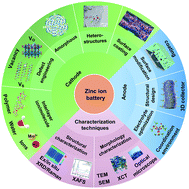
Aqueous zinc-ion batteries (ZIBs) have been increasingly studied in recent years due to their low cost and high safety and the high abundance of natural zinc resources. However, the practical application of ZIBs has been restricted due to some challenges, including the low electrochemical activity of their cathodes, sluggish diffusion kinetics of Zn2+, structural instability during long-term cycling, formation of dendrites and occurrence of side reactions on zinc anodes. Structural and defect engineering has been developed to address these challenges. Herein, recent progress regarding the structural and defect engineering of aqueous ZIBs is summarized, mainly focusing on introducing interlayer ions/molecules and vacancies/defects into the cathode crystal structure, designing amorphous structures and/or heterostructures of cathodes, decorating an inorganic/organic coating on cathodes, creating an artificial interfacial layer on anodes and constructing nanostructured anodes. Additionally, advanced techniques in structural and defect engineering that are used for aqueous ZIBs are further summarized. Furthermore, the existing challenges and future prospects of the structural and defect engineering of ZIBs are discussed.


image file: d1ta03620c-p1.tif

Min Du

Min Du obtained his B.S. degree from Qingdao University in China in 2017. She has been a Ph.D candidate in Prof. Hong Liu's group at the State Key Laboratory of Crystal Materials, Shandong University, China since September 2017. Her research interests are aqueous zinc batteries.

image file: d1ta03620c-p2.tif

Zhenyu Miao

Zhenyu Miao has been a doctoral student in Prof. Hong Liu's group at the State Key Laboratory of Crystal Materials, Shandong University, China since September 2017. His research interests are anode materials for aqueous zinc batteries.

image file: d1ta03620c-p3.tif

Houzhen Li

Houzhen Li has been a master's student in Prof. Hong Liu's group at the State Key Laboratory of Crystal Materials, Shandong University, China since September 2020. His research interests are lithium metal anode batteries.

image file: d1ta03620c-p4.tif

Yuanhua Sang

Prof. Dr Yuanhua Sang obtained his B.S. degree from Shandong University in China in 2007 and received his Ph.D degree from Shandong University in July 2012. Now, he works as an associate professor at the State Key Laboratory of Crystal Materials, Shandong University, China. His research interests are the structure and property investigation of inorganic crystal materials with neutron and X-ray diffraction, functional materials, and nano-materials for solar light conversion, especially for photocatalysis and photothermal applications.

image file: d1ta03620c-p5.tif

Hong Liu

Prof. Dr Hong Liu is a professor at the State Key Laboratory of Crystal Materials, Shandong University. He received his Ph.D degree in 2001 from Shandong University (China). His current research is mainly focused on the chemical processing of nanomaterials for energy related applications including photocatalysis and tissue engineering, especially the interaction between stem cells and the nanostructure of biomaterials, as well as nonlinear optical crystals.

image file: d1ta03620c-p6.tif

Shuhua Wang

Prof. Dr Shuhua Wang is a professor at the State Key Laboratory of Crystal Materials, Shandong University. She received her Ph.D degree in 2016 from the Beijing Institute of Nanoenergy and Nanosystems, Chinese Academy of Sciences. Her current research is mainly focused on rechargeable batteries, nanogenerators, and the application of nanomaterials in regulating the fate of stem cells and/or immune cells.


1. Introduction

In response to the current energy and environmental crises, the demand for new green energy sources, such as solar energy, geothermal energy, wind energy, and other renewable energy sources, is increasing.1–5 Currently, renewable energy is generally transported and stored in the form of electricity.6 Therefore, the development of reliable and stable power conversion and energy storage technologies is critical to enable the efficient use of renewable energy.7–9 Batteries, which are energy storage devices that convert chemical energy into electrical energy, have been increasingly studied and have undergone several developments since their invention.10,11 Currently, lithium-ion batteries (LIBs) are widely used as commercial batteries, and their high energy density (150–265 W h kg−1; 400–770 W h L−1) and long cycle life have become a research topic in the international energy storage field in recent years.12,13 Nevertheless, the development of LIB technology is constrained by potential safety hazards due to the flammable nature of their liquid electrolytes and the economic challenges of obtaining the scarce resources that are required.14,15 In this era of the emergence of a “smart society”, there is an urgent need for rechargeable secondary batteries with high energy density, low cost, good cycling performance, safety and environmental friendliness.

Aqueous rechargeable batteries based on multivalent metal cations such as zinc,16 aluminum,17 and magnesium ions18 have attracted considerable attention owing to their environmental friendliness, low cost, high safety, and high energy density. Among them, aqueous zinc ion batteries (ZIBs), consisting of cathode materials, separators, zinc anodes and electrolytes, are considered ideal green battery systems. When ZIBs are in operation, zinc ions transfer in an insertion/extraction mechanism on the cathode, while relevant zinc deposition/stripping occurs on the anode.19 Owing to the two-electron transfer in the redox reaction, ZIBs can provide high capacity and energy density.20 In addition, mild or slightly acidic aqueous electrolytes are less harmful to the human body and environment. However, many critical issues remain to be resolved. First, the poor intrinsic electrical conductivity of the cathode material limits electron and charge transport during the redox reaction.21 A higher electrical conductivity will certainly endow the cathode with superior reaction kinetics. Second, divalent zinc ions have strong electrostatic interactions with the cathode material, which limits the diffusion of zinc ions and its reversibility.22 Third, most cathode materials, such as vanadium-based materials (VO223 and V2O5 (ref. 24)) and manganese-based materials25 (Mn2O3 and MnO2), usually inevitably dissolve in the electrolyte, potentially resulting in irreversible capacity loss and decreased stability. Additionally, poor stability arises from the phase transition of the cathode during cycling, which results in a large volumetric change and structural collapse.26 Apart from the challenges associated with cathodes, the zinc anode suffers from the growth of Zn dendrites and side reactions.7,9 Owing to the irregular electric field and “tip effect”, Zn ions spontaneously diffuse and accumulate at preferential nucleation sites and form dendrites on the anode side, leading to ZIBs experiencing internal shorting failure. Moreover, due to the influence of active water molecules, side reactions including hydrogen evolution and Zn corrosion take place on the surface of the anode, leading to ZIBs demonstrating unsatisfactory stability and poor reversibility.14

Based on the above observations, extensive efforts have been made to alleviate these problems, and considerable advancements have been made. Structural and defect engineering has been recognized as an effective strategy and has been widely adopted in the realm of ZIBs. Recently, some excellent reviews have been reported on aqueous zinc-ion batteries from different perspectives,27–29 but a comprehensive review of structural and defect engineering for aqueous zinc-ion batteries has not yet been systematically reported. Hence, this study fills the above gap by focusing on the structural and defect engineering of high-performance rechargeable aqueous ZIBs. We first introduce the intercalation of ions and/or molecules in cathode materials and describe the function of ions and/or molecules in the crystal structure or interlayer. Then, the strategies and effects of defect engineering are discussed. Third, recent progress in structural and defect engineering for cathode materials, including amorphous structures, heterostructures, and surface coatings, is systematically summarized. Next, we summarize and discuss concerns about the Zn anode, including the formation of Zn dendrites and water-induced side reactions (hydrogen evolution and Zn metal corrosion). Then from a structural engineering point of view, we proposed possible solutions. In addition, some advanced characterization techniques used for the investigation of ZIBs are summarized. Finally, we propose our perspectives on new directions for the structural and defect engineering of zinc anodes, which may lead to the future development of high-performance aqueous ZIBs.

2. Structural and defect engineering of cathode materials

Although various kinds of materials have been reported as cathodes for aqueous ZIBs, their sluggish kinetics, poor electronic conductivity, structural collapse, and dissolution restrict the further development of ZIBs.30,31 Thus, a suitable design of the cathode material is crucial for improving the electrochemical performance of aqueous ZIBs. In this section, structural and defect engineering strategies to modulate the properties of cathode materials and improve their performance are presented in detail.

2.1 Ion/molecule intercalation

The introduction of interlayer ions (e.g., Li+, Na+, K+, Mg2+, Ca2+, Ba2+, Zn2+, Fe2+, Cu2+, Mn2+, Al3+, Ag+, La3+, NH4+, and N(CH3)4+) can effectively tune the crystal structure of cathode materials,32–44 which is beneficial for promoting zinc ion diffusion during the discharge–charge process. In addition, the introduced ions can act as pillars to prevent the collapse of the layered structure after Zn2+ (de)intercalation, thereby improving the stability of the cathode during long-term cycling.45 The reported preintercalated metal ions are summarized in a periodic table (Fig. 1a). Molecules have also been introduced into layered cathode materials. For example, structural water molecules have been verified to play a key role in weakening electrostatic interactions with the oxide framework, thus facilitating the reaction kinetics during the electrochemical process.46,47 Additionally, organic molecules have been demonstrated to reduce electrostatic interactions between zinc ions and oxides, enhancing the reversibility of Zn2+ (de)intercalation.48,49
image file: d1ta03620c-f1.tif
Fig. 1 (a) Periodic table of cations (marked with pink color) that have been introduced into cathode materials. (b) Crystal structure of Zn0.25V2O5·nH2O. Reproduced with permission.38 Copyright 2016, Springer Nature. (c) XRD pattern of Ca0.25V2O5·nH2O. Reproduced with permission.36 Copyright 2018, Wiley-VCH. (d) Element content of dissolved Mn2+ in a 2 M ZnSO4 aqueous electrolyte during the cycling of KMO and α-MnO2. (e) Schematic of the incorporation of K+ ions stabilizing the Mn polyhedrons. (d and e) Reproduced with permission.68 Copyright 2019, Wiley-VCH. (f) XRD patterns of MnVO and VOH. Reproduced with permission.69 Copyright 2019, Royal Society of Chemistry. (g) XRD patterns of Al–VOH and VOH. Reproduced with permission.40 Copyright 2020, Elsevier.
2.1.1 Introduction of single ions. Intercalated divalent zinc ions usually exhibit stronger electrostatic interactions with the host framework than monovalent Li+ ions,50,51 which hinders reversible zinc ion insertion/extraction and causes capacity fading. The preintroduction of ions has proven to be a positive strategy to solve the capacity fading problem of V-based cathodes during long-term cycling.52 The capacity retention could be improved by the pinning effect from the introduced metal ions, as the pillars stabilize the layered structure.53 The strong bonding between preintercalated metal ions and guest ions effectively prevents structural collapse during repeated Zn2+-ion (de)intercalation storage.36 For instance, V3O8 layers with sodium ions (NaV3O8·1.5H2O, NVO) as the cathode for aqueous ZIBs were reported to exhibit a capacity retention of 82% over 1000 cycles and the mass loading was 2 mg cm−2.54 The preintroduced sodium ions in the interlayers of NVO work as pillars to stabilize the crystal structure and prevent structural collapse upon zinc ion insertion/extraction. Divalent ions possess stronger ionic bonding with oxygen atoms in the VO framework than alkali metal ions,36 contributing to its superior structural durability. Nazar's group investigated Zn0.25V2O5·nH2O (ZVO) as a cathode for ZIBs,38 in which the V2O5 layers were pinned by ZnO6 octahedra, as shown in Fig. 1b. Zinc ions act as pillars in the interlayers of ZVO, which are conducive to stabilizing the crystal structure during cycling, thereby causing a reversible phase transformation process and reversible Zn2+ insertion/extraction. Similarly, divalent calcium ions were also introduced into the V2O5 layers (Ca0.25V2O5·nH2O, CVO) as the cathode for aqueous ZIBs.36 The Ca–O bonds (2.38–2.57 Å) are much longer than the Zn–O bonds (2.03–2.13 Å); thus, CVO exhibits a larger interlayer spacing than ZVO (Fig. 1c). Besides, compared with the chemical bonding of Zn–O (284.1 kJ mol−1),55 Ca atoms are deemed to possess larger chemical bonds with O atoms (464 kJ mol−1); thus, Ca can serve as much stronger “pillars” between the VO layers to improve the structural stability of the cathode material for reversible Zn2+ migration. Given the superior pinning effect, a small number of calcium ions have been reported to stabilize the V2O5 framework via a simple chemical pre-intercalation,56 demonstrating that the capacity does not decay even after 3000 cycles at 10 A g−1. Apart from the aforementioned metal ions, other metal ions such as K+, Ag+, Mn2+, Co2+, and Ba2+ have also been reported to work as pillars between two VO layers,34,37,43,57,58 preventing the crystal structure from being damaged. NH4+ ions have also been preintercalated into vanadium oxide to stabilize the layered framework during cycling because of its pillaring effect.59

This strategy is also suitable for manganese oxide cathodes. To date, (α-, β-, γ-, ε-, and δ-) MnO2, Mn2O3, and Mn3O4 have been used as cathodes for aqueous ZIBs.60–62 However, manganese oxides undergo structural transformation and collapse during cycling, resulting in poor stability.63,64 Preintercalated metal ions can effectively solve the above problem by acting as pillars that stabilize the framework. For example, a layered framework of MnO2 nanospheres with zinc-ion pillars as the cathode for ZIBs was prepared via a facile chemical reaction,65 which exhibited a high capacity of 124 mA h g−1 at a current density of 3 A g−1 and an outstandingly long lifespan of over 2000 cycles. Similarly, Ca ions were also verified to stabilize layered δ-MnO2 (Ca0.28MnO2·0.5H2O).66 Benefiting from the pinning effect of Ca2+ ions, the structural stability was strengthened. Thus, the cathode delivered a much higher capacity of 135 mA h g−1 at 1.5 A g−1 after 300 cycles than the δ-MnO2 cathode (54.9 mA h g−1) and manifested a significantly long cycle life of over 5000 cycles. Cu2+-intercalated layered MnO2 also exhibited long-term cycling stability for over 6000 cycles.67 The high reversibility and durability of the cathode during cycling can be ascribed to the redox reaction of the intercalated Cu2+. Cu2+ was reduced to Cu during the discharge process, which decreased the charge transfer resistance (Rct) during the redox reaction and ensured that δ-MnO2 underwent a reversible phase transition from the dissolved state (Mn(OH)2) to the initial state upon charging. In addition, preintercalated metal ions (K+) were also deemed to play a critical role in alleviating manganese dissolution and preventing structural degradation.68 Liang and coworkers found that the dissolution of Mn in Mn8O16 incorporated with K+ ions was effectively suppressed even after 50 cycles (Fig. 1d). As shown in Fig. 1e, the intercalated K+ ions bonded with oxygen atoms in the MnO6 polyhedrons, which strengthened the stability of the tunnel structure and suppressed Mn dissolution.

In addition to the pinning effect, the inserted metal ions could also enlarge the interlayer spacing of V-based oxides, providing more active sites for zinc ion storage. Because of the (de)intercalation-type storage mechanism of ZIBs, an abundance of zinc-ion storage spaces is a crucial factor for endowing active materials with excellent electrochemical performance. Moreover, an expanded interlayer distance reduces the strong interaction between the intercalated Zn2+ ions and host materials, thereby promoting zinc-ion diffusion. For example, Li+ was intercalated into the interlayer of V2O5·nH2O (LVO-250),32 increasing the d-spacing of (001) from 12.00 to 13.77 Å. The expanded lattice spacing was conducive to Zn2+ insertion and extraction, facilitating Zn2+ diffusion and enhancing structural stability. Thus, the LVO-250 cathode delivered a high capacity of 192 mA h g−1 at 10 A g−1 after 1000 cycles, while the cathode without Li+ intercalation exhibited inferior long-term cycling performance. Preinserted Mn2+ in hydrated vanadium pentoxide (MnVO) expands its lattice spacing.69 Hydrated vanadium pentoxide has an interlayer spacing of 11.9 Å (Fig. 1f), which enlarges to 12.9 Å after introducing Mn2+. Similarly, the X-ray diffraction (XRD) peaks of V2O5·nH2O preinserted with Al3+ (Al–VOH) also shifted toward a lower degree (Fig. 1g),40 suggesting the expansion of the interlayer spacing, which was calculated to be 13.4 Å. Although Al3+ and Mn2+ have similar ionic radii of 53.5 and 58 pm, respectively, the interlayer spacing of Al–VOH is much larger than that of MnVO. This can be ascribed to Al3+ exhibiting a higher valence than Mn2+; thus, Al3+ exhibits stronger electrostatic repulsion with V5+ in the VO framework. Benefiting from the widened interlayer spacing, Al–VOH delivers an obviously enhanced durability without any capacity fading during long term cycling for over 3000 cycles at 4 A g−1. In addition, the interlayer spacing was enlarged by 5.68 Å after the preintercalation of Cu2+ ions into the interlayer of V2O5 (CuVO-300).39 The zinc ion diffusion coefficient of CuVO-300 was demonstrated to increase by one order of magnitude compared to that of VO-300. Apart from Cu2+, other transition metal ion (Fe2+, Co2+, Ni2+, Mn2+, and Zn2+) intercalated V2O5 delivered higher zinc-ion diffusion coefficients than VO-300. The enhanced electrochemical performance of the cathode with intercalated metal ions was related to the enlarged interlayer spacing, which promoted ion migration during the zinc ion storage process.

The introduced metal ions also increase the electrical conductivity of the electrode to sufficiently improve electrochemical performance. For example, compared with Zn0.25V2O5·nH2O,38 Ca2+-inserted V2O5 (Ca0.24V2O5·0.83H2O) exhibited a fourfold higher electrical conductivity,36 which is conducive to electron transfer in electrochemical reactions and improves electrochemical performance. Transition metal ions have also been reported to optimize the electrochemical energy storage of cathodes for ZIBs, mainly because of their unique electronic structures. As shown in Fig. 2a and b, the calculated band structure shows that the indirect bandgap of V2O5 doped with Mn2+ ions is 0.90 eV,57 which is smaller than that of pure V2O5 (2.28 eV). This bandgap can boost the transfer of charge carriers to the conduction band and improve conductivity. The calculated projected density of states (PDOS) verified that the major 3d orbitals of vanadium and the minor 2(s + p) state of oxygen contribute together to the conduction and valence bands. In particular, a new energy level appears near the Fermi level after the introduction of Mn, which leads to a 40% decrease in the bandgap. Moreover, the charge distribution of layered V2O5 after Mn2+ intercalation was tuned, as shown in Fig. 2c. Specifically, electrons accumulated in the yellow region and depleted in the blue region. Thus, the electronic conductivity of layered V2O5 was significantly improved after doping with Mn2+. In addition, a multivalence cobalt-doped Mn3O4 (Co–Mn3O4) cathode has been reported for high-performance ZIBs,70 and the different chemical states of doped cobalt ions play different roles. Co2+ doping into the interlayer of [MnO6] octahedra acts as a pillar to strengthen the layered structure of δ-MnO2. The Co4+ ions located on the layers enhance the conductivity of Mn4+ in the [MnO6] octahedron. The calculated exfoliation energies (Eads) show that the doped Co2+ on δ-MnO2 has a larger Eads (1.28 eV) than the typical δ-MnO2 (0.19 eV), suggesting that the stability of the layered structure is strengthened after doping with Co2+. As shown in Fig. 2d, the density of states (DOS) results reveal that δ-MnO2 doped Co4+ shows a band gap of 1.04 eV, which is smaller than that of δ-MnO2 (1.16 eV). This result is related to the lower energy band gap of the layer-doped Co4+, which improves the conductivity. More importantly, the doped Co ions (Co2+ and Co3+) can effectively inhibit the Jahn–Teller effect of the discharge products. The Mn3+ derived from species (ZnMnOx or MnOOH) generated in the discharge state led to Mn(III) dissolution in the aqueous electrolyte. The crystal orbital Hamilton population (COHP) value of the MnOOH-doped Co ions (Co2+ and Co3+) is higher than that of MnOOH (Fig. 2e). That is, the bonding state increased, and the anti-bonding state decreased. Thus, the dissolution of Mn ions was effectively alleviated and the stability of the layered structure was enhanced.


image file: d1ta03620c-f2.tif
Fig. 2 (a and b) Calculated total band structures and electron density difference of pure V2O5 and Mn2+-doped V2O5. (c) Electron density difference of Mn2+-doped V2O5. (a–c) Reproduced with permission.57 Copyright 2019, Wiley-VCH. (d) DOS of MnO2 and Co4+–δ-MnO2. (e) COHP of MnO6 (the c-axis) at different positions of MnOOH. (d and e) Reproduced with permission.70 Copyright 2020, Wiley-VCH. (f) Schematic illustration of the energy versus DOS in Co0.247V2O5·0.944H2O and V2O5·nH2O cathodes. (g and h) The optimized configuration of Zn-adsorbed Co0.247V2O5·0.944H2O and V2O5·nH2O frameworks, respectively, and their corresponding adsorption energies. The gray spheres represent adsorbed Zn atoms, and Co atoms are depicted as blue spheres. (i) The diffusion energy barrier profiles of Co0.247V2O5·0.944H2O and V2O5·nH2O. (f-i) Reproduced with permission.58 Copyright 2019, Wiley-VCH.

Other interesting advancements have been reported after doping with metal ions in host materials. For instance, the voltage of the host cathode is improved after doping guest ions. Zhi's group found that cobalt ion-doped V2O5 (Co0.247V2O5·0.944H2O) as a cathode for ZIBs delivered a higher operational voltage of 1.7 V than that of the Zn/V2O5·nH2O battery (lower than 1 V).58 On the one hand, the increased voltage was caused by the unique electronic structure of Co0.247V2O5·0.944H2O. The interaction between the Co 3d and V 3d orbitals shifted the redox potential of V5+/V4+ to a higher level based on electronic structure analyses (Fig. 2f), thus increasing the operational voltage of the cathode. On the other hand, the high voltage is related to the increased absorption energy of Zn2+. As displayed in Fig. 2g and h, the adsorption energy for the Zn atom in V2O5·nH2O is 1.85 eV, which increases to 2.24 eV after doping with cobalt ions. Besides, the diffusion energy barrier significantly decreases from 0.58 eV to 0.15 eV after preintercalating Co ions into V2O5 (Fig. 2i), suggesting that Co0.247V2O5·0.944H2O is more suitable for fast Zn-ion diffusion. Thus, Co-doped V2O5 exhibits a capacity of 432 mA h g−1 at 0.1 A g−1 and the capacity above 1.0 V is 227 mA h g−1 (52.54% of its total capacity). In contrast, the capacity of the Zn/vanadium oxide system above 1.0 V is usually less than 19% of the total capacity, which is less than 70 mA h g−1. Apart from providing a high voltage, it has also been reported that the guest ions participate in the electrochemical reaction to boost the capacity of the cathode. For example, the redox reaction between Co3+ and Co4+ in cobalt-ion-doped Mn3O4 can contribute to additional capacity.70 Thus, the multiple electrochemical reactions for Zn ion storage endow the cathode with a high capacity. A novel layered iron vanadate (Fe5V15O39(OH)9·9H2O) cathode was prepared as for aqueous ZIBs,71 in which Fe and V were both subjected to oxidation–reduction reactions during the zinc-ion storage process and contributed to a high capacity of 385 mA h g−1 at 0.1 A g−1.

2.1.2 Introduction of single molecules. As a high-performance cathode material for aqueous ZIBs, it is generally believed that the crystal water in the cathode framework significantly affects its electrochemical performance. Specifically, crystal water plays a crucial role in facilitating zinc-ion migration, mainly owing to its “water-lubricating” effect and enlarged interlayer spacing (Fig. 3a).47 Structural water acting as a charge screening medium reduces the effective charge of H2O-solvated zinc ions and effectively weakens the electrostatic interactions between intercalated Zn2+ and the active species. Owing to the ‘‘water-lubricating” effect, V2O5·nH2O delivered excellent rate performance and a remarkably long lifespan compared to V2O5 without structural water. Density functional theory (DFT) calculations were performed to theoretically elucidate the vital role of structural water. Choi's group investigated the possible Zn-ion diffusion paths and kinetic energy barrier for zinc ion diffusion in V6O13 with and without structural water.72 As shown in Fig. 3b, because the strong electrostatic repulsion was reduced in the hydrous structure, the migration pathway of Zn2+ ions along the b-axis exhibits a zigzag route. The Zn2+ ion moves straight forward and leans to one side in the structure without water (Fig. 3c). In addition, as shown in Fig. 3d, the structure with water shows a larger cross-sectional area (formed by V and O) than the structure without water. This is related to the larger unit cell volumes in the hydrous structure when zinc ions intercalate into the structure. The DFT results also suggest that the kinetic barrier for Zn ion diffusion in V6O13 with structural water is much smaller than that of the vanadium oxide without structural water, which are 0.87 eV and 2.85 eV (Fig. 3e), respectively. This lower Zn2+ migration energy barrier was also verified in an inorganic open-framework (IOF) phosphovanadate cathode (KV2O4PO4·3.2H2O) with abundant lattice water.73 Benefiting from the “charge shield” of crystal water, the kinetic barrier for Zn ion diffusion in the hydrous structure is 0.66 eV along the b-axis, which is smaller than that in the structure without water (0.81 eV).
image file: d1ta03620c-f3.tif
Fig. 3 (a) The proposed crystal structures of pristine V2O5·nH2O, and V2O5·nH2O after charging to 1.3 V, and discharging to 0.2 V. Reproduced with permission.47 Copyright 2017, Wiley-VCH. Diffusion paths of Zn ions (b) with and (c) without water (projected down [001]). (d) Change in the cross-sectional area of the diffusion path during Zn intercalation with and without water. (e) Calculated diffusion barriers for paths in (b) and (c). (b–e) Reproduced with permission.72 Copyright 2019, Wiley-VCH. (f) Schematic of Na ion and water molecule pre-intercalated δ-MnO2 for Zn ion storage. Reproduced with permission.76 Copyright 2019, American Chemical Society. (g) Schematic illustration of the reaction mechanism of ρ-CaVO. Reproduced with permission.78 Copyright 2019, American Chemical Society.

Apart from the water-lubricating effect, the structural water intercalating into the layers of the host cathode can increase the interlayer distance. For example, layered manganese oxide containing crystal water (cw-MnO2) was proven to have a d-spacing of 7.25 Å,74 in which the content of crystal water was up to ∼10 wt%. To reveal the role of crystal water, cw-MnO2 was heat-treated at 100 and 300 °C to obtain samples with different water contents. As expected, the sample capacity and long-term cycling performance gradually decreased with a reduced water content. Thus, it can be concluded that the improved cycling stability of the cathode is associated with appropriate interlayer spacing and a high content of crystal water, which relieves the dissolution of manganese and maintains its structural stability. Besides, water-incorporated MoS2 nanosheets were reported. The XRD patterns showed that the diffraction peaks of the (002) plane in hydrated MoS2 shifted to a lower angle than that of dehydrated MoS2.75 This revealed that the intercalated structural water led to a larger interlayer spacing, which was beneficial for reducing the Zn2+ diffusion resistance. According to the electrochemical impedance spectroscopy (EIS) results, hydrated MoS2 exhibits a much smaller Rct (1.6 Ω) than dried MoS2 (150 Ω), suggesting that the charge transfer kinetics were effectively improved. In addition, the zinc-ion diffusion coefficient of hydrated MoS2 is three orders of magnitude higher than that of dried MoS2. Moreover, the desolvation barrier of hydrated zinc ions in MoS2 during the discharge process also decreased. This was attributed to the interlayer water could relay the solvation water of hydrated Zn2+ when the Zn2+ intercalated into the MoS2.75 Structural water incorporated with other ions can also be used to expand the interlamellar spacing. For instance, water with preintercalated Mg2+ into the interlayers of V2O5 delivers a wide interplanar spacing of 13.4 Å.35 Besides, Na+ ions and water molecules were cointroduced into layered δ-MnO2 (Na0.44Mn2O4·H2O) and the interlayer spacing increased to 0.72 nm (Fig. 3f).76 The synergy between the expanded interlayer spacing and water-lubricating effect is beneficial for reducing electrostatic interactions between the inserted zinc ions and VO framework and facilitating the diffusion of zinc ions, which endows the cathode with outstanding cycling stability and reversibility.

In addition to the preintercalated structural water in the preparation process mentioned above, water molecules in the electrolyte solution were also inserted into the interlayer of the cathode during the energy storage process. For instance, the d-spacing of the (001) plane of NH4V4O10 expands from 9.8 Å to 11.1 Å after immersion in an aqueous electrolyte,77 which is associated with the intercalation of solvent water to enlarge the interlayer distance. In addition, the (001) plane of the cathode in the charge state was still larger than that of the original NH4V4O10 powder, suggesting that the intercalated solvent water remained in the layered structure of NH4V4O10 during the zinc-ion insertion/extraction process. The inserted water synergizes with NH4+ to maintain structural stability, effectively reducing the strong electrostatic reaction between Zn2+ and the VO framework. Similarly, solvent water was intercalated into the layers of Ca0.67V8O20·3.5H2O (CaVO) after soaking in an aqueous electrolyte,78 expanding d001 from 10.68 to 13.03 Å. The solvent water was expelled from the interlayer of CaVO after the insertion of zinc ions in the discharge state. Upon charging, the solvent water was intercalated into the interlayer again, accompanied by zinc ion extraction (Fig. 3g).

In addition to the intercalation of water molecules, organic molecules have also been successfully intercalated into layered host materials. For instance, polyaniline (PANI) was intercalated into the layers of V2O5via an in situ hydrothermal reaction,79 causing an increased interlayer distance (13.90 Å) and effectively facilitating Zn2+ diffusion. More importantly, the special π-conjugated structure of PANI blocked the electrostatic interactions between Zn2+ and O2−. The DFT results show that the Fermi level is near the conduction band and that an intermediate level appears across the Fermi level after intercalating PANI, which accelerates electronic transport and zinc-ion migration. PANI was also successfully introduced into MnO2, which reinforced the layered structure.80 Moreover, the guest PANI synergized with nanosized (∼10 nm) MnO2 to eliminate the phase changes during cycling and maintain a stable layered structure. Thus, the cathode exhibited long-term cycling stability for 5000 cycles at a current density of 2 A g−1 with a capacity utilization of 40%. Additionally, poly(3,4-ethylenedioxythiophene) (PEDOT) was embedded into layered V2O5 near the grain surface via in situ polymerization,48 triggering zinc ions to reach deeper interlayers due to the cascading effect. DFT calculations show that there are three possible Zn2+ diffusion pathways based on the enlarged interlayer spacing of V2O5@PEDOT. In contrast, V2O5 possessed only one suitable site for Zn absorption and the corresponding absorption energy was higher than that of V2O5@PEDOT. Thus, the preintercalated PEDOT promotes zinc-ion diffusion kinetics in the layered V2O5 framework. Moreover, the shallow-layer pillaring of PEDOT tends to suppress the dissolution of the cathode due to its hydrophobic character.

2.1.3 Introduction of dual ions/molecules. As summarized in the previous section (2.1.1), various metal ions can be used as guest ions in cathode materials. Apart from single ions, dual ions were introduced into the crystal structure to optimize the electrochemical performance. For example, a Na+ and Ca2+ coinserted V3O8 layered structure (NaCa0.6V6O16·3H2O, NaCaVO) was successfully prepared (Fig. 4a).81 The intercalated cations (Na+/Ca2+) stabilized the layered structure during long-term cycling. More importantly, the diffusion barriers of Zn2+ in NaCaVO were obviously decreased, suggesting that the intercalated Na+/Ca2+ could promote zinc-ion migration. However, the introduction of Na+/Ca2+ into the crystal structure did not improve the conductivity of the cathode.
image file: d1ta03620c-f4.tif
Fig. 4 (a) Experimental and Rietveld-refined XRD patterns; inset: the crystal structure of NaCaVO viewed along the b-axis. Reproduced with permission.81 Copyright 2019, Wiley-VCH. (b) Density of states of NVO, Mn1-NVO, and MnVO. (c) Possible migration pathways for Zn2+ in Mn1-NVO. (d) Energy barriers along Zn2+-migration pathways for Mn1-NVO.82 (e) Schematic of Zn2+ diffusion in the discharged state in TMAVO. (f) Computation model of [N(CH3)4]V8O20. (g) Results of bond overlap populations of Zn–C and Zn–O for [N(CH3)4]V8O20. (e–g) Reproduced with permission.42 Copyright 2020, Zhengzhou University. Schematic illustration of the preparation process of PEDOT-intercalated NVO-layered material. (h) Illustration of structural changes. (i) Description of simulation changes. (h and i) Reproduced with permission.83 Copyright 2020, Elsevier.

According to a previous report, transition metal ions enhance the conductivity,39 resulting in the improvement of electrochemical performance. The ion transport and electronic conductivity of the cathode can be improved simultaneously through doping with different ions. Based on this, a transition metal ion and alkali metal cation were preinserted into a V8O20 electrode together.82 Preinserted Mn2+/Mn3+ increased the electrical conductivity of the vanadium-based cathode, and preinserted Na+ promoted zinc-ion diffusion. Notably, (Na0.97,Mn0.02)V8O20·0.32H2O (Mn1-NVO) exhibits a higher electron density near the Fermi level than NaV8O20 (NVO) (Fig. 4b), indicating that the preintercalated Mn ions contribute to an enhanced electrical conductivity. In addition, NVO shows a lower energy barrier for Zn2+-migration along the b-axis than Mn1-NVO and MnV8O20 (MnVO) (Fig. 4c and d), suggesting that compared to Mn ions, Na ions play a more crucial role in boosting zinc ion diffusion. Moreover, the Mott–Schottky plots show that NaV8O20 doped with transition metal (Mn, Fe, Co, and Ni) ions exhibits a higher charge carrier density than alkali metal (K and Ca) ion-intercalated NaV8O20. In addition, the Tafel curves demonstrated that the transition metal ions introduce the “catalytic effect” to accelerate the electron transfer and redox reaction.

The ionic radius of organic cations is usually larger than that of metal ions, which makes them promising candidates for interlayer intercalation. A V8O20 cathode cointercalated with metal ions (Zn2+) and organic ions ([N(CH3)4]+) was prepared as a cathode for ZIBs (Fig. 4e).42 The zinc ions cooperated with [N(CH3)4]+ and acted as pillars to stabilize the crystal structure. More importantly, as shown in Fig. 4f and g, Zn–C exhibits a lower bond overlap population (0.18) than Zn–O (0.33, 0.28, and 0.33) based on the DFT calculated results, and Zn–C has a longer bond length (2.43 Å) than Zn–O (2.16, 2.27, and 2.16 Å). These results suggest that the intercalated zinc ions during discharge form a weaker interaction with the carbon in [N(CH3)4]+ than with the oxygen atoms in the VO framework, which is conducive to reversible zinc-ion insertion/extraction. In addition to dual-ion cointercalation, conductive polymers cointercalated with inorganic ions have also been realized in vanadium-based host materials. For example, an NH4+ and PEDOT cointercalating V3O8 layered structure was used as a cathode for ZIBs.83 As shown in Fig. 4h and i, the interplanar spacing of the NH4V3O8 cathode is 7.8 Å, which is further expanded to 10.8 Å after introducing PEDOT. This enlarged spacing promoted the stability of the cathode due to the increased migration pathway for Zn2+ storage. Furthermore, based on DFT calculations, NH4V3O8 with inserted PEDOT was also demonstrated to have a lower zinc-insertion energy due to a larger interlayer space. Thus, the strategy of two dual-ion insertions may combine the advantages of different ions or polymers and endow the cathode with excellent energy storage behavior.

2.2 Defect engineering

Defect engineering is a powerful strategy that can significantly affect the electronic and crystal structures of electrode materials. For instance, introducing vacancies has been regarded as an important strategy to optimize the electrochemical performance of the cathode for ZIBs.84,85 Here, we summarize the strategies for introducing oxygen vacancies, sulfur vacancies, and cationic vacancies. In particular, we focus on the effect of defect engineering on Zn2+ storage. Defect engineering can promote the kinetics of electrode materials, form abundant active sites, and stabilize the electrode structure; these are discussed in detail below.
2.2.1 Strategies for introducing defects. Introducing anion defects is a promising strategy to modulate the electronic properties of cathode materials.86 Oxygen defects are the most common form of anionic defects. Introducing oxygen defects usually requires a reducing environment. One possible method involves the use of chemical reagents with strong reducibility. Because of the strong reducibility of H in NaBH4, the use of NaBH4 solution is a cost-effective and easy method to introduce oxygen defects at room temperature. For instance, VO2(B) with oxygen defects was prepared by reducing with NaBH4 solution.87 After the reduction process, oxygen defects were successfully introduced into the crystal structure and the chemical formula of VO2(B) changed to VO1.88.

Another method is heat treatment in a reducing atmosphere. Birnessite-MnO2 with oxygen defects was prepared through calcination with NaBH4 at 400 °C.88 A H2 reduction atmosphere was generated in situ when NaBH4 was heated at high temperature. The reducing H2 atmosphere could also be introduced by using a H2/N2 mixed gas flow. Oxygen-deficient ZnMn2O4 was successfully prepared by annealing ZnMn2O4 powder in a reducing atmosphere (H2/N2 mixed gas).89 The volume ratio of H2/N2 was 3/1 and the flow rate was 200 sccm with a ramp rate of 2 °C min−1. Apart from H2, PH3 and NH3 gases could also be used to create a reducing atmosphere. Nickel cobaltite (NiCo2O4) nanosheets were annealed in the presence of NaH2PO2·H2O at 300 °C in a N2 atmosphere.90 The generated PH3 gas from NaH2PO2·H2O was used to reduce NiCo2O4 and introduce oxygen vacancies into nickel cobaltite (NiCo2O4−x). Notably, MnO2 easily transforms into Mn3O4 if the heat treatment temperature rises above 300 °C.91 Thus, abundant oxygen defects were successfully introduced into the MnO2 branch through a low-temperature (200 °C) treatment process with a gas flow of NH3 for 2 h at a heating rate of 10 °C min−1. Meanwhile, N was doped into MnO2 in an atmosphere of NH3 gas.

In addition, oxygen-deficient active materials can be obtained only through annealing at high temperatures without a reducing atmosphere. For example, K0.8Mn8O16 with oxygen vacancies was prepared using a thermal treatment method at 800 °C in a muffle furnace.68 The oxygen atoms easily escape from the VO framework at high temperatures, leaving oxygen defects in K0.8Mn8O16. Apart from the oxygen defects in oxides, sulfur vacancies are ubiquitous in sulfides. Sulfur-deficient MoS2−x nanosheets were prepared by sintering in an argon atmosphere at 250 °C.92 Interestingly, when the sintering temperature was increased to 750 °C, defect-free MoS2 with high crystallinity was obtained. Thus, the introduction of defects can be realized at appropriate calcination temperatures.

Besides calcination, the hydrothermal method is a facile technique for introducing oxygen defects. Vanadium bronzes (NH4V4O10) with oxygen deficiencies (Od-NVO·nH2O) were fabricated through a one-step hydrothermal reaction.93 Oxygen vacancies were successfully introduced into the cathode materials after increasing the amount of oxalic acid and adding extra ammonium fluoride during synthesis. The synergistic effect between the reducing reagent (oxalic acid) and NH4F introduced oxygen defects and etched the microstructure of NH4V4O10. Apart from the hydrothermal reaction, the solid diffusion process is another effective technique for introducing oxygen defects under mild conditions. For instance, tunneled α-MnO2 with oxygen defects was synthesized through surface gradient Ti doping.50 First, MnO2 nanowires were prepared by the hydrothermal method, and then TiO2 was grown on MnO2 nanowires via atomic layer deposition. Owing to the substantial difference in the Fermi level between Ti4+ and Mn4+, the Ti atoms substituted the Mn atoms in the [MnO6] octahedra. Thus, Ti was doped into MnO2 and was simultaneously accompanied by the generation of oxygen vacancies.

Cation vacancies have also been introduced into cathode materials to improve their electrochemical performance. Recently, cation deficient Zn0.3(NH4)0.3V4O10·0.91H2O was reported as a cathode for aqueous ZIBs through a two-step hydrothermal reaction.94 First, NH4V4O10 was synthesized, followed by another hydrothermal reaction, in which Zn2+ was preintercalated into NH4V4O10 and simultaneously created cation vacancies. Also, a cation-deficient spinel ZnMn2O4 cathode was successfully prepared through a two-step method.95 In the synthesis process, NH3·H2O was added to the precursor, which assisted in oxidation precipitation. The mixture was then crystallized to the spinel phase with cation redistribution after heating at 180 °C in air, and cation deficiencies were produced. Cation defects can also be produced during an electrochemical reaction process. Mn-defect MnO was fabricated through an in situ electrochemical extraction approach.96 The X-ray photoelectron spectroscopy (XPS) results showed that the distance between the splitting peaks decreased after the first charging, indicating that the oxidation state of Mn increased. This was attributed to the Mn2+ extracted from the MnO framework into the aqueous electrolyte during the initial charge process, leaving Mn defects in the MnO host. Similarly, a disordered rocksalt vanadium oxynitride (VNxOy) with abundant vacancies/defects was constructed through a conversion reaction in an aqueous electrolyte during the initial charge process.97 The abundant low-valent oxygen (O2−) in the rocksalt vanadium oxynitride was substituted by high-valent anion nitrogen (N3−) during the initial charge, producing abundant vacancies previously occupied by vanadium.

2.2.2 Effect of defects. Defect engineering has been increasingly demonstrated to play a significant role in boosting the energy storage performance of cathodes for aqueous ZIBs. The introduced defects in a cathode structure ameliorate the inherent deficiencies in the zinc-ion storage process, such as its sluggish kinetics, poor conductivity, unstable crystal structure, and insufficient active sites. This section discusses the critical effects of defect engineering on promoting the electrochemical performance of cathodes, including promoting kinetics, improving conductivity, and increasing active sites.

(1) Defects can promote the kinetics of electrode materials. In particular, oxygen defects are among the most powerful strategies to effectively weaken the strong interaction between intercalated zinc ions and a vanadium oxide cathode. Various vanadium-based cathode materials (V4O10, V6O13, and VO2) with oxygen defects have been widely explored.93,98,99 For instance, oxygen-deficient V6O13 (Od-VO) has been reported as a cathode for ZIBs.98 Because of the extraction of electronegative oxygen atoms from the VO framework, reversible Zn2+ insertion/extraction is promoted during cycling. This is mainly because of the decreased interactions between the oxygen atoms and divalent Zn2+. Thus, the Od-VO cathode in the discharge and charge states exhibits much higher Zn2+ diffusion coefficient (DZn) values of 1.1 × 10⁻¹¹ and 0.4 × 10⁻¹¹ cm2 s−1 respectively, than the defect-free structure. Moreover, the zinc ion diffusion pathway is usually along the ab plane in the layered crystal structure of vanadium-based compounds.38,58 The presence of oxygen vacancies in Od-VO may open up the layered structure of vanadium oxide, enabling the diffusion of zinc ions along the c-axis except for the pathway along the ab plane (Fig. 5a and b), thus promoting the reaction kinetics. A similar function of oxygen defects providing another channel for ion transport was reported for a β-MnO2 cathode.100 The presence of oxygen defects not only provided an extra pathway in the [MnO6] polyhedron walls for guest-ion diffusion but also provided more ion absorption sites. Benefiting from this, oxygen-deficient β-MnO2 exhibited a higher capacity and reversibility than β-MnO2. The capacity retention of oxygen-deficient β-MnO2 was 94% after 300 cycles at 0.5 A g−1. In comparison, the commercial β-MnO2 cathode delivered a lower capacity retention of 78%.


image file: d1ta03620c-f5.tif
Fig. 5 Structure of (a) p-VO and (b) Od-VO. (a and b) Reproduced with permission.98 Copyright 2019, Wiley. (c) Calculated diffusion barriers for paths in perfect KVO and O-defective KVO. Reproduced with permission.101 Copyright 2019, Wiley. (d) Calculated Zn ion diffusion energy barriers in VO2 and VO1.75. Reproduced with permission.99 Copyright 2020, American Chemical Society. (e) The projected density of states (PDOS) and the total density of states (TDOS) of defective and perfect NVO. Reproduced with permission.93 Copyright 2020, Royal Society of Chemistry. (f) The calculated adsorption energies for Zn2+ on the surfaces of perfect σ-MnO2 and σ-MnO2 with oxygen vacancies. Reproduced with permission.102 Copyright 2019, Wiley. (g) Schematic illustration of interlayer expanded MoS2. (h) Schematic illustration of hydrophilicity tuning. (g and h) Reproduced with permission.103 Copyright 2019, American Chemical Society.

In addition, oxygen defects play a crucial role in reducing the Zn-ion diffusion energy barrier to promote zinc ion diffusion, which was further analyzed through DFT calculations. As shown in Fig. 5c, oxygen-defective potassium vanadate (KVO) exhibits a significantly lower Zn2+ diffusion barrier (0.63 eV) than the perfect KVO structure (1.34 eV),101 verifying that the oxygen vacancies can accelerate Zn2+ diffusion. Besides, the lower diffusion energy barrier in the structure with oxygen defects was also verified in a tunnel-like structure with values of 0.24–0.71 eV and 0.78 eV for VO1.75 and VO2 along the b tunnel,99 respectively, as shown in Fig. 5d. Thus, oxygen defects can reduce the migration energy barrier of Zn2+ ions in the cathode structure and promote the reaction kinetics.

(2) Oxygen defects can improve the electronic conductivity of the active material, which is one of the most important factors affecting electron transfer and electrochemical performance. For instance, enriched oxygen defects were introduced into a hydrated NH4V4O10 cathode (Od-NVO·nH2O) to regulate the electronic structures, exhibiting a higher capacity (435 mA h g−1) than that of NVO (405 mA h g−1).93 This superior electrochemical performance is associated with an improvement of conductivity. As shown in Fig. 5e, the calculation results demonstrate that the defect states (gap states) of the defective NVO were closer to the Fermi level than the perfect NVO. Also, the defect states (donor) were located near the conduction band minimum (CBM) based on the results of the projected density of states (PDOS) and the total density of states (TDOS). Thus, the electrons at the donor level can be easily excited into the conduction band, leading to the improved electronic conductivity of the defective NVO and accelerating electron transport during the electrochemical reaction process. In addition, electron migration was promoted by constructing an oriented electric field in oxygen-defective α-MnO2, which was prepared through surface gradient Ti doping.50 The substitution of Ti and derived oxygen vacancies in the crystal structure forms a depletion zone and induces a local in-plane electric field, which is beneficial for facilitating ion diffusion/electron transport. The redox reaction during the zinc ion storage process is strongly associated with the electron transport rate. Thus, the synergy between ion migration and electron transport contributed to the superior energy storage behavior of the cathode materials.

Apart from oxygen defects, cationic defects can also increase the conductivity. Mn atoms extracted from the MnO crystal structure into an electrolyte leave behind Mn cation defects (Mn0.610.39O, □ refers to the Mn defect) after the first charging process.96 The charge density of MnO with Mn defects around the Fermi level was higher than that of pristine MnO, as revealed by the DOS results, which resulted in better conductivity. Moreover, the Mn cation defects induced the accumulation of electrons near the defects and attracted the intercalation of zinc ions. The introduced defects in the host structure modulate the charge distribution and enhance the conductivity, promoting the reaction kinetics during the Zn2+ storage/release process and improving the electrochemical performance.

(3) The presence of defects provides abundant active sites for zinc-ion storage. For example, oxygen vacancies have been successfully introduced into manganese oxide to improve the attainable capacity. The Gibbs free energy of oxygen-deficient MnO2 for Zn2+ adsorption is approximately 0.05 eV around the oxygen vacancy (Fig. 5f),102 which is very close to thermoneutral values. In contrast, pristine MnO2 exhibits a much lower Gibbs free energy (≈−3.31 eV). This result indicates that the adsorption/desorption of zinc ions is more reversible on oxygen-deficient MnO2 than on pristine MnO2. Furthermore, a renewed active surface area is available for the next adsorption, which aids in enhancing the capacity. In addition, a larger number of electrons contribute to the delocalized electron cloud, further improving the capacity of the cathode. Hence, oxygen-deficient MnO2 exhibits a higher capacity of 345 mA h g−1 at a current density of 0.2 A g−1 than MnO2 (270 mA h g−1).

Apart from the above cathodes, defect engineering also endows the layered metal disulfides with more active sites. For example, sulfur-deficient MoS2−x nanosheets can act as cathodes for ZIBs,92 which ameliorate the poor electrochemical activities of 2H-MoS2 for Zn-ion storage. MoS2 with introduced defects possesses many edge sites and vacancies, which offer more active sites for zinc ion storage. In addition, the increased interlayer spacing also results in the availability of more sites for zinc-ion storage and the fast diffusion of Zn2+ ions. Thus, the defect-rich MoS2−x nanosheets delivered a high reversible capacity of 88.6 mA h g−1 even after 1000 cycles at 1 A g−1, and exhibited a capacity retention of 87.8%. In addition to sulfur defects, the incorporation of heteroatoms into MoS2 has also been demonstrated to provide more active sites. The inactive cathode for zinc-ion intercalation was converted into functionally active materials via oxygen incorporation (MoS2–O).103 The replacement of sulfur with oxygen atoms increased the interlayer spacing from 6.2 to 9.5 Å (Fig. 5g), which endowed the layered structure with more space to store zinc ions. In addition, the incorporation of oxygen atoms also played an important role in enhancing the hydrophilicity of MoS2 (Fig. 5h). Thus, the Zn2+ storage capacity improved 10-fold and the Zn2+ diffusivity of the MoS2–O cathode increased by three orders of magnitude.

2.3 Amorphous structures

Crystal structures exhibit sluggish zinc-ion migration and often undergo phase transitions and structural collapse.104–106 Compared with crystal materials, amorphous cathodes contain abundant defects and active sites, which enhance pseudocapacitive charge storage properties and high rate capability.106,107 A metal–organic framework-derived composite including amorphous V2O5 and carbon materials (a-V2O5@C) was prepared using an in situ electrochemical induction strategy.108 The prepared Zn/a-V2O5@C batteries exhibited major pseudocapacitance behavior in their capacity contribution compared with the c-V2O5 (crystalline V2O5) and a-V2O5 cathodes (Fig. 6a), which results in excellent rate capability. The dominant pseudocapacitance and superior rate performance can be ascribed to the amorphous structure of V2O5, which endows the composite cathode with more isotropic Zn2+ diffusion pathways and active sites. Thus, the amorphous composite of a-V2O5@C exhibits a high capacity of 620.2 mA h g−1 at 0.3 A g−1. Even when the current density reaches 200 A g−1, the composite displays a capacity of 72.8 mA h g−1. Besides, the a-V2O5@C cathode shows a higher Zn2+ diffusion rate than c-V2O5 and a-V2O5 (Fig. 6b), confirming that the amorphous structure helps to realize fast kinetics during zinc-ion insertion/extraction. Amorphous V2O5 has a lower Zn2+ (de)intercalation energy (1.02 eV) than the corresponding crystalline phase (2.28 eV) based on first-principles calculations (Fig. 6c), further indicating that the transport of Zn2+ in amorphous V2O5 is easier than that in crystalline V2O5. Moreover, the electrochemical performance of the composite is further enhanced due to the porous carbon framework, which endows the cathode material with abundant electron transport pathways and ion migration channels. Thus, the cathode exhibits unprecedented cycling performance. Even after 20[thin space (1/6-em)]000 cycles at a high current density of 40 A g−1, the capacity is still up to 249.2 mA h g−1 and the capacity retention is 91.4%.
image file: d1ta03620c-f6.tif
Fig. 6 (a) Capacitive contributions at various scan rates. (b) The Zn2+ diffusion coefficient during discharging. (c) Illustration of Zn2+ diffusion and Zn2+ (de)intercalation energy in crystalline and amorphous V2O5 from first-principles calculations. (a–c) Reproduced with permission.108 Copyright 2020, Wiley. (d) XRD patterns of FeVO-1. (e) Percentages of pseudocapacitive contribution at different scan rates of FeVO-1. Reproduced with permission.109 Copyright 2020, American Chemical Society.

Recently, amorphous ternary vanadium oxide (FeVO4) was calcined at 250 °C (FeVO-1) as a cathode for ZIBs and crystalline FeVO was obtained at a higher temperature of 500 °C (Fig. 6d).109 Amorphous FeVO-1 has a high specific surface area of 80.9 m2 g−1 and has abundant mesopores with an average pore width of ∼15.9 nm. These pores provide more spaces for zinc-ion storage and increases the contact area between the electrolyte and cathode. The kinetic mechanism of FeVO-1 was investigated by analyzing the CV curves at different scan rates. It was demonstrated that pseudocapacitance dominates the electrochemical reaction process (Fig. 6e), especially at high current density. Moreover, the bimetallic oxide exhibits higher electronic conductivity than V2O5. Benefiting from these advantages, amorphous FeVO4 exhibits improved zinc-ion diffusion kinetics and fast surface Zn2+ storage. Thus, compared to highly crystalline FeVO-1, amorphous FeVO-1 delivers a higher capacity and superior long-term cycling stability at 1 A g−1.

In addition to vanadium oxide, crystalline manganese oxide as an attractive cathode for aqueous ZIBs usually suffers from phase transitions and structural collapse during cycling, leading to poor long-term cycling performance.110,111 Thus, an amorphous manganese dioxide (A-MnO2−δ) was fabricated by generating short-range ordered distorted Mn–O polyhedra.106 A-MnO2−δ was verified to have a decreased Mn valence and abundant oxygen vacancies. The disordered network array provided more ion-storage active sites to enhance the capacity. In addition, the abundant structural defects endowed the cathode with a better capability to store ions, which boosted ion transfer across the interface between the A-MnO2−δ cathode and electrolyte. Furthermore, the A-MnO2−δ cathode exhibited a dominant pseudocapacitive contribution due to its abundant structural defects and intrinsic isotropic nature, which facilitated the reaction kinetics. As a result, the A-MnO2−δ cathode exhibited a high capacity of 301 mA h g−1 at 0.1 A g−1 and a high capacity retention of 78% after 1000 cycles at 1 A g−1. In short, an amorphous framework with the unique property of intrinsic isotropic nature endows the cathode materials with abundant structural defects and active sites for zinc ion storage, which makes a significant pseudocapacitive contribution during the electrochemical reaction process and promotes the reaction kinetics.

2.4 Designing heterostructures

The strategy for designing amorphous structures shows unique advantages in developing high-performance cathode materials with fast ion intercalation and high-rate performance. Constructing a heterostructure incorporated with a unique amorphous structure is a reliable strategy to fully exploit the merits of individual compounds. For example, a 2D sandwich-like heterostructure combining amorphous vanadium pentoxide and graphene (A-V2O5/G) was successfully prepared through an ion adsorption approach.107 The transmission electron microscopy (TEM) image shows heterostructures with an ultrathin flat morphology (Fig. 7a). The high resolution TEM (HRTEM) image without any lattice fringes and selected area electron diffraction (SAED) without diffraction spots both confirmed the amorphous structure (Fig. 7b). The A-V2O5/G heterostructure exhibited an ultrahigh capacity of 489 mA h g−1 at 0.1 A g−1 and a remarkable rate capability of 123 mA h g−1 even at an ultrahigh current density of 70 A g−1. Its outstanding energy storage behavior can be ascribed to strong synergy between the heterostructure materials. First, the amorphous structure provides abundant active sites for zinc-ion storage and tolerates the large volume variation upon cycling. Second, graphene with a high electrical conductivity accelerates electron transport. Third, the ultrathin nanosheet (∼5 nm) structure shortens the ion diffusion pathway. Thus, the heterostructure combines the advantages of the amorphous V2O5 structure and graphene to enhance the capacitive-controlled kinetic process and improves the conductivity, thereby achieving an ultrahigh capacity and rate capability.
image file: d1ta03620c-f7.tif
Fig. 7 (a) TEM image of A-V2O5/G heterostructures. (b) HRTEM image and SAED pattern (inset) of A-V2O5/G. Reproduced with permission.107 Copyright 2020, Wiley. (c and d) The migration energy barriers with the variation of the MoS2-to-graphene distance. (h) Density of states of bulk MoS2 and MoS2/graphene. (c, d and h) Reproduced with permission.112 Copyright 2021, Wiley. Low magnification (e) and high magnification (f) HRTEM images of α-(Mn2O3–MnO2). The inset of (f) shows the SAED pattern with diffraction spots for α-(Mn2O3– MnO2). (g) Fast Fourier transform image in HRTEM image (e). (e–g) Reproduced with permission.113 Copyright 2020, American Chemical Society. (i and j) The HRTEM images of VS2/VOx. (k) The cycling performance of VS2/VOx and VS2 at 1 A g−1. (i–k) Reproduced with permission.114 Copyright 2020, Wiley.

In addition, graphene was intercalated into the MoS2 framework, forming a sandwich-like heterostructure (MoS2/graphene) as a cathode for high-performance aqueous ZIBs.112 Notably, bulk MoS2 is almost purely the 2H-phase, while MoS2 in the heterostructure shows a high 1T-phase content. The synergistic effect of 1T-MoS2 and rGO with abundant oxygen-containing groups improved the hydrophilicity of MoS2. In addition, the interlayer spacing of MoS2 was 0.62 nm, which apparently enlarged to 1.16 nm after the introduction of graphene into the gallery. To investigate the diffusion dynamics of the heterostructure, the Zn2+ migration barriers were calculated via DFT computations. Bulk MoS2 exhibited an ion migration barrier of 0.991 eV (Fig. 7c), which was much higher than that of the MoS2/graphene heterostructure. Moreover, the DFT results showed that the Zn2+ migration barriers gradually decreased as the MoS2-to-graphene distance increased (Fig. 7d). When the distance between MoS2 and graphene was 4.86 Å, the Zn2+ migration barrier was 0.425 eV. After expanding the distance to 6.5 Å, the value of the Zn2+ migration barrier was reduced to 0.024 eV. The lower ion migration barriers indicate fast kinetics during the zinc-ion insertion/extraction process. DFT was also conducted to analyze the density of states (DOS) of the heterostructure and bulk MoS2. As displayed in Fig. 7h, the heterostructure shows considerable states at the Fermi level, revealing the metallic properties of MoS2/graphene with high electronic conductivity. In contrast, bulk MoS2 is a semiconductor because it has an ∼0.8 eV bandgap. Therefore, benefiting from the low Zn2+ migration barriers and improved conductivity, the heterostructure exhibits excellent electrochemical performance.

A similar DFT result was obtained for twinborn α-(Mn2O3–MnO2) heterostructures,113 which were prepared by an in situ phase transformation after calcination. The HRTEM images show the coexisting lattice fringes of α-Mn2O3 and α-MnO2, confirming the formation of heterojunctions (Fig. 7e–g). Mn2O3 and MnO2 show obvious band gaps, revealing their insulating nature. However, the α-(Mn2O3–MnO2) heterostructure shows a DOS peak crossing the Fermi level, suggesting its metallic nature. This results in improved electrical conductivity, which accelerates Zn2+ diffusion and promotes charge transport. Moreover, the heterostructure displays a DOS peak and its center is located at the Fermi level, indicating that the heterostructure possesses improved electronic conductivity and fast redox kinetics. Therefore, the α-(Mn2O3–MnO2) heterostructure shows superior reversibility and high chemical reactivity.

In addition, a heterostructure of VS2/VOx was fabricated by the in situ oxidation of VS2 to VOx during the initial charging process.114 The HRTEM images show that the VOx in the heterostructure consists of V6O13, V2O5 and VO2 (Fig. 7i and j). Owing to the electric field formed at the interfaces of the heterostructure, electronic migration is enhanced. Due to the high conductivity of VS2 and the high chemical stability of VOx, the heterostructure of VS2/VOx delivers superior long-term stability to pure VS2 (Fig. 7k). Furthermore, the average working voltage of VS2/VOx is higher than that of VS2, which is increased by 0.25 V. Thus, the heterostructure exhibits a higher energy density of 280 W h kg−1 compared to VS2 (208 W h kg−1) based on their similar capacities. As proven by these reports, the construction of a heterostructure is a promising strategy for producing a cathode with high electrochemical performance. The heterostructure combines the merits of both compounds to achieve high conductivity, abundant active sites, and a stable structure. As a result, the heterostructure shows the synergistic effect between them, thus enhancing the kinetics and improving capacity.

2.5 Surface coating

Generally, most active materials for ZIBs suffer from poor intrinsic conductivity, dissolution in aqueous electrolytes, and phase transition during long-term cycling, which leads to architectural collapse and capacity decay.115,116 Surface coating is an effective strategy to modulate the surface properties of the cathode. It not only forms a protective interfacial layer to prevent the cathode from directly contacting with the electrolyte but also inhibits the continuous side reactions between the cathode and electrolyte. In this section, the current coating layer is summarized and classified into two types, inorganic and organic surface coating layers.
2.5.1 Inorganic surface coating layers. A carbon coating layer has been widely applied to various cathode materials. The conductive carbon layer coating significantly improves the electrical conductivity of the cathode, which is beneficial for accelerating electron transfer during the redox reaction. A MnOx nanorod coating with N-doped carbon nanowalls (MnOx@N–C) was prepared, and a schematic of the structure is shown in Fig. 8a.117 The porous N-doped carbon was derived from a metal–organic framework (MOF) of ZIF-8 nanoparticles through a calcination process. The porous framework of the carbon coating layer promoted the reaction kinetics. On the one hand, due to the conductive carbon network, the electronic conductivity was enhanced and the electron transport was accelerated. On the other hand, the porous structure led to abundant ion transport channels, boosting zinc-ion transport. In addition, the dissolution of Mn ions is suppressed because of the carbon coating layer on the cathode surface, which avoids direct contact with MnOx and aqueous electrolytes. As a result of these merits of porous N-doped carbon, the MnOx@N–C composite delivers a high capacity of 305 mA h g−1 after 600 cycles at 0.5 A g−1. Besides, homemade waste litchi shell-derived mesoporous carbon materials (MCMs) were used to coat α-Mn3O4 particles.118 MCM4 (WMCMs[thin space (1/6-em)]:[thin space (1/6-em)]WKOH = 1[thin space (1/6-em)]:[thin space (1/6-em)]4) with abundant mesoporous structures provides a large number of channels for zinc-ion storage. MCM4 also enhances the electronic conductivity of the MCM4@Mn3O4 cathode and promotes electron transfer. In addition to these composites, other active cathode material coating carbon layers have been widely investigated, including Ni3S2/carbon,119 (NH4)2V3O8/C,120 ZnMn2O4@C,121 N-doped C/V2O3,122 MnO@N–C,123 and Mn3O4@NC.124
image file: d1ta03620c-f8.tif
Fig. 8 (a) Schematic of the structure of MnOx@N–C nanorods. Reproduced with permission.117 Copyright 2018, Wiley. (b) Schematic illustration of the structure of H2V3O8 NW/graphene. (c) TEM image of H2V3O8 NWs on graphene films. (b and c) Reproduced with permission.51 Copyright 2018, Wiley. (d) TEM images and SAED (inset) of α-MnO2/graphene scrolls. (e) The HRTEM of α-MnO2/graphene scrolls. (d and e) Reproduced with permission.126 Copyright 2018, Wiley. (f) Schematic illustration of a flexible and foldable ZIB cell. (g) Cycling stability of the ZIB cell under different mechanical deformations. (f and g) Reproduced with permission.129 Copyright 2020, Wiley. (h) The battery reaction mechanism schematic diagram of α-MnO2 and Ca2MnO4. Reproduced with permission.131 Copyright 2019, American Chemical Society. (i) Area% change of H2PO4 and PO3 at the surface of PCO as a function of annealed temperature. (j) Specific capacitances of different PCO samples prepared under various conditions as a function of scan rate. (i and j) Reproduced with permission.132 Copyright 2016, Wiley.

Other carbon materials, such as graphene, reduced graphene oxide (rGO), and carbon nanotubes (CNTs), have also been combined with cathodes to optimize their electrochemical performance. For example, graphene sheets were used to wrap H2V3O8 nanowires (NWs) via a simple hydrothermal method and the mass loading of the cathode was approximately 1 mg cm−2.51 The graphene network intimately surrounds the random NWs (Fig. 8b and c) and provides a large contact area with H2V3O8 NWs, which benefits the charge transport kinetics. Graphene also plays an important role in improving the surface area. As shown by the BET result, H2V3O8 NW/graphene has a larger surface area (21.5 cm2 g−1) than pure H2V3O8 NWs (14 cm2 g−1), which increases the contact area between the electrolyte and cathode. In addition, the high specific area of the graphene sheet enhances the capacity due to the capacitive effect. Thus, the composite cathode of H2V3O8 NW/graphene delivers a high capacity of 394 mA h g−1 at 1/3C, an excellent rate performance of 270 mA h g−1 at 20C and outstanding cycling stability (87% capacity retention after 2000 cycles). Besides, graphene combined with CNTs forms a unique three-dimensional (3D) scaffold (rGO/CNT),125 which was incorporated with one-dimensional (1D) NaxV2O5·nH2O (NVO) nanobelts to construct a 3D cross-linked structure. The 3D rGO/CNT architecture accelerates zinc-ion diffusion because of the enhanced contact area between the electrolytes. In addition, the 3D rGO/CNT architecture provides a 3D electron pathway, leading to fast electron transport. 3D rGO/CNT also works as an elastic medium to tolerate the volume change of the active material during Zn2+ insertion/extraction, resulting in long-term cycling stability.

Apart from vanadium-based compounds, this strategy has also been applied to manganese-based cathodes. As shown in Fig. 8d, graphene scroll-coated α-MnO2 nanowires were successfully fabricated.126 The HRTEM image shows that the thickness of multilayer rGO was 5 nm (Fig. 8e). On the one hand, the rGO coating layers prevent the dissolution of MnO2 in the aqueous electrolyte during cycling. On the other hand, rGO improves the electronic conductivity of MnO2 nanowires. Thus, the composite electrode shows an excellent long-term cycling stability (94% capacity retention after 3000 cycles at 3 A g−1) and a high energy density of 406.6 W h kg−1 at 0.3 A g−1. Due to its mechanical deformability, light weight, and high electrochemical conductivity,127 reduced graphene oxide was hybridized with other active materials as a flexible and foldable cathode.128 As shown in Fig. 8f, a self-standing hybrid membrane consisting of ultralong MnO2 nanowires and graphene nanosheets was fabricated as a highly flexible and lightweight cathode for ZIBs.129 The foldable ZIB cathodes showed no capacity decay when the flexible cell was bent and folded (Fig. 8g).

In addition to the carbon coating layer, other inorganic compounds were also coated on the cathode surface. For instance, rose-like VS2 nanosheets were coated with a protective layer of VOOH (VS2@VOOH) via a facile hydrothermal method.130 Hydrophilic VOOH with a thickness of 50–100 nm plays an important role in suppressing the dissolution of vanadium, which acts as a protective layer to separate VS2 and the aqueous electrolyte. This may be related to the O–H in VOOH, which exchanges with the O–H in water during cycling and keeps the VOOH structure stable. Additionally, electrolyte is beneficial to infiltrate into cathode due to the presence of hydrophilic O–H, which promotes the efficiency of zinc-ion diffusion. Thus, the VS2@VOOH composite delivers superior cycling stability and exhibits a 91.4 mA h g−1 capacity even after 400 cycles even at a high current density of 2.5 A g−1 and an 82% capacity retention.

The inorganic compound coating layer can also be generated through an in situ electrochemical method. An in situ formed solid electrolyte interface (SEI) layer (CaSO4·2H2O) was fabricated on the Ca2MnO4 cathode surface during the charging process.131 DFT calculations were performed to analyze the properties of the SEI layer. The DOS results reveal that the SEI layer is an electron insulator because its bandgap is 7.2 eV. Moreover, the zinc-ion diffusion energy barrier is only 0.357 eV in the SEI layer, suggesting that the SEI layer also has superior ionic conductivity. As shown in Fig. 8h, the insoluble SEI layer coating on the cathode surface suppresses the dissolution of Mn ions and prevent the crystal structure of the cathode from collapsing. In short, because of the in situ generation of the SEI film on the cathode surface, the ion transport kinetics at the interface are improved, the activation energy for zinc ion diffusion is reduced and dissolution is inhibited. This endows the Ca2MnO4 cathode with excellent capability and cycling stability, which shows a capacity of 100 mA h g−1 and a capacity retention of 80% after 1000 cycles at a current density of 1 A g−1.

Inorganic ion coating has also been exploited to improve electrochemical performance. The modified inorganic ion groups on the cathode surface play an important role in tuning the interfacial properties. For instance, surface-modified phosphate groups ((H2PO4) and (PO3)) have been demonstrated to effectively promote surface reactivity and efficient charge storage.132 Phosphate-ion-functionalized Co3O4 was used for pseudocapacitors. The effect of different contents of the two phosphate groups on the pseudocapacitive performance was analyzed. With an increase in PO3, the specific capacitance decreases while the rate capability increases (Fig. 8i and j). In addition, the electrode with the highest content of (H2PO4) shows the smallest equivalent series resistance. It was concluded that H2PO4 contributes to fast electron transport and that PO3 promotes interfacial redox reactions. Moreover, Co–OPO(OH)2 exhibits a higher degree of covalency than Co–O because Co–OPO(OH)2 shows a higher covalent character (67.7%) than Co–O (54.4%), indicating that the electrons in the 3d orbitals of the Co atom in Co–OPO(OH)2 possess higher energy. Besides, the Co–OPO(OH)2 bond possesses a longer length (≈2.09–2.19 Å) than the Co–O bond (≈1.9 Å). The longer bond and lower electronegativity weaken the attraction of electrons in the 3d orbitals of cobalt ions, which reduces the energy for electrons extracted/obtained during the redox reactions. Thus, the modified phosphate ions enhance the surface reactivity of the cathode and promote electrode kinetics, leading to fast faradaic reactions.

Similarly, cobalt molybdate (CoMoO4) nanosheets with surface-modified phosphate ions (P–CoMoO4) were fabricated via a phosphating process,133 which also introduced oxygen vacancies in the structure and generated CoP nanoparticles on the nanosheets. Due to the modified phosphate ions on the surface, the activation energy of redox reactions is decreased and the reaction kinetics are promoted. The CoP nanoparticles generated in situ on the nanosheets enhance the active sites and boost the charge transfer. The electronic conductivity is also enhanced because of the presence of oxygen vacancies. Thus, the optimized P–CoMoO4 cathode shows a higher capacity of 431.4 mA h g−1 at a current density of 10 A g−1 compared with CoMoO4 (157.5 mA h g−1), and delivers an outstanding energy density of 679.4 W h kg−1 at a power density of 8.6 kW kg−1.

The incorporation of inorganic compounds and inorganic ions was used to modify active materials for ZIBs. For instance, a P–MoO3−x@Al2O3 cathode was prepared as a cathode for ZIBs via unique interfacial engineering.134 First, α-MoO3 nanorods were prepared through a hydrothermal method, and then Al2O3 was coated on the nanorod surface by atomic layer deposition (ALD) technology. Finally, phosphating treatment was performed to introduce phosphate ions and oxygen vacancies. The unique structural design optimized the electrochemical performance of the electrode. On the one hand, the coated Al2O3 as a protective layer suppressed the dissolution of active materials and tolerated the volume variation of the cathode during cycling, resulting in long-term cycling performance. On the other hand, the introduced phosphate ions and oxygen vacancies enhanced the electrical conductivity and promoted surface reactivity. Therefore, the P–MoO3−x@Al2O3 sample exhibited the highest capacity and best cycling stability compared to the uncoated Al2O3 layer (P–MoO3−x) and pure MoO3 samples.

2.5.2 Organic surface coating. Generally, the electrical conductivity of the cathode significantly influences the electrochemical performance. The organic coating layer usually improves the electronic conductivity, but it exhibits relatively moderate ion diffusion compared to the inorganic coating layer.135 Various polymers have been reported as coating layers on the cathode surface to optimize the electrochemical performance, such as polyfurfural,136 polyaniline (PANI),137 polypyrrole (PPY),138 polydopamine (PDA),139 poly(3,3′-dihydroxybenzidine) (DHB),140 poly(3,4-ethylenedioxythiophene) (PEDOT),141 and poly(styrenesulfonate) (PSS).142

Specifically, a V2O5 array grown on carbon cloth (CC) was coated with a conductive layer of PEDOT through the electrodeposition method.141 The HRTEM image shows PEDOT coated V2O5 with a thickness of 5 nm (Fig. 9a). V2O5 with the PEDOT coating layer realizes a higher capacity retention of 65% compared to V2O5@CC (40%) and pure V2O5 (7%) when the current density is increased from 0.2 to 20 A g−1. In addition, the V2O5@PEDOT/CC composite electrode shows 89% capacity retention after 1000 cycles when cycled at a current density of 5 A g−1 (Fig. 9b), which is much higher than the 41% and 11% for V2O5@CC and V2O5, respectively. The optimized electrochemical performance of the V2O5@PEDOT/CC cathode can be ascribed to the following reasons: first, PEDOT acts as a conductive layer to improve the electronic conductivity of V2O5, which is beneficial for improving the reaction kinetics. Second, PEDOT works as an active material to improve the capacity of the composite cathode.


image file: d1ta03620c-f9.tif
Fig. 9 (a) TEM image of the as-prepared V2O5@PEDOT nanosheet arrays. (b) Cycling performances of V2O5@PEDOT/CC, V2O5/CC, and V2O5 powders at 5 A g−1 for 1000 cycles. Reproduced with permission.141 Copyright 2018 Wiley. (c) Schematic diagram of the polar direction of glutamate adsorbed on MoS2 when the electric double layer is formed. (d) Schematic diagram of zinc-ion hydration, migration and dehydration in a zinc-ion battery using Glu-MoS2. (e) Water contact angle test of the MoS2 film and Glu-MoS2 film. (f) Interfacial tension diagram of MoS2 and Glu-MoS2 with water. (c–f) Reproduced with permission.143 Copyright 2020, Elsevier. (g) Water contact angles of MnO2 and MNG cathodes before cycling. (h) Cycling performance and corresponding coulombic efficiency of MnO2 and MNGs at 5C after the activation process at 0.5C. (g and h) Reproduced with permission.144 Copyright 2020, Elsevier.

In addition to a single polymer, two different kinds of polymers have been used to optimize the electrochemical performance of the cathode material. A PEDOT:PSS film with the addition of 1-ethyl-3-methylimidazolium-hexafluorophosphate ionic liquid ([EMIM]PF6) was coated on a Bi2S3 electrode to construct a high-performance zinc-ion battery.142 The unique film performs several functions in improving the electrochemical performance. First, the PEDOT:PSS film greatly increases the cathode conductivity, resulting in accelerated electron transfer upon reaction. Second, the polymer layer prevents the inner Bi2S3 grains from pulverizing and alleviates the dissolution of sulfur. Benefiting from the versatile [EMIM]PF6–PEDOT:PSS polymer layer, the modified Bi2S3 cathode shows a reversible capacity of 275 mA h g−1 at 0.3 A g−1, and excellent long-term cycling stability (95.3% capacity retention for over 5300 cycles).

Apart from the aforementioned polymer layers, another organic coating layer plays a unique role in modulating the dehydration process and improving the wettability between the electrode and electrolyte. Hydrated zinc ions ([Zn(H2O)6]2+) in an aqueous electrolyte hardly intercalate into the host structure because of their large size of 5.5 Å.103 This means that hydrated zinc ions undergo dehydration during intercalation into the cathode framework. Thus, accelerating the dehydration process is a key factor for boosting the ion migration kinetics. Glutamate possesses –NH3+, which can trigger interfacial polarization to catalyze the dehydration of hydrated zinc ions, leading to fast Zn2+ intercalation. Thus, glutamate was adsorbed on the MoS2 surface (Glu-MoS2) to improve the electrochemical performance.143 As displayed in Fig. 9c, there is an electric double layer between the cathode and electrolyte after the cathode and anode form a closed circuit. On the one hand, the –NH3+ in glutamate bonds with oxygen ions in hydrated zinc ions (Fig. 9d), pulling water over and accelerating the dehydration process. On the other hand, the electric field of –NH3+ weakens the bond between Zn2+ and H2O and reduces the activation energy. The wetting properties of Glu-MoS2 in water are improved, which shows smaller contact angles than MoS2 (Fig. 9e and f). This higher hydrophilicity endows the cathode surface with good contact with the electrolyte. Thus, Glu-MoS2 exhibits a 2.5 times higher specific capacity than pure MoS2.

In addition to glutamate, cellulose was also applied to modulate the wettability of the electrode. Cellulose nanowhiskers (CNWs) and graphene coated on MnO2 nanowires were used to investigate the influence of electrode wettability on electrochemical performance.144 It is difficult for water molecules to infiltrate graphene due to its hydrophobicity. CNWs are amphiphilic compounds, which can be hybridized with graphene in water. The hydrophobic face of CNWs interacts with the π-conjugated system of graphene, forming a CH–π interaction. As a result, the hydrophilic face of CNWs with many hydroxyl groups is in contact with water. The wettability of the composite cathode can be further turned through changing the ratio of graphene to CNWs. As shown in Fig. 9g, with a decrease in the CNW content from 37.50% (MNG-1) to 16.67% (MNG-2) and then to 6.25% (MNG-3) and 3.85% (MNG-4), the hydrophobicity of the cathode is enhanced. The cycling performance initially increases with an increase in hydrophobicity (Fig. 9h). It was explained that the hydrophobic surface accelerated the desolvation of hydrated Zn2+, promoting the zinc-ion diffusion kinetics. However, the electrochemical performance decreased with a further increase in hydrophobicity, which led to slow zinc-ion transportation and charge transfer.

3. Metal Zn anode

3.1 Issues for the Zn anode

As mentioned above, intensive study efforts have been made on cathode materials via structural and defect engineering for high-performance rechargeable aqueous ZIBs.145–147 Compared with cathodes, Zn metal anodes have attracted increasing attention in the last two years. Although Zn metal anodes can mitigate negative issues to some extent in acidic or neutral electrolytes compared to alkaline electrolytes, they are still plagued by unsatisfactory stability, poor reversibility and a low coulombic efficiency (CE).7,14 This is mainly caused by the formation of Zn dendrites and water-induced side reactions (including hydrogen evolution and Zn metal corrosion). To achieve high-performance ZIBs, it is essential to construct a stable Zn metal anode. In this section, we concisely summarize the problems with Zn anodes, from the aspects of dendrite formation and side reactions.
3.1.1 Zn dendrite growth. Zinc dendrite growth is considered the primary challenge for the development of high-performance Zn metal anodes. Zn dendrites inevitably form and grow rapidly in alkaline electrolytes during cycling, which severely reduces the electrochemical performance of ZIBs. Although the growth of dendrites can be moderated to some extent in mild electrolytes, this remains a challenge that cannot be ignored.148 The reaction mechanisms of Zn metal anodes for ZIBs with neutral aqueous electrolytes such as ZnSO4 involve the reversible deposition/stripping of Zn2+, which can be summarized as follows:
Zn ↔ Zn2+ + 2e

Unfortunately, this process is usually inhomogeneous, mainly related to the uneven current density distribution on the electrode surface. In addition, it is acknowledged that diffusion plays a dominant role during plating. Specifically, Zn2+ is primarily adsorbed on the surface of the electrode through two-dimensional (2D) diffusion to accumulate at preferential nucleation sites and form the initial bulge, which increases the partial Zn2+ concentration and aggravates the uneven electric field distribution of the electrode.149 Subsequent Zn2+ tends to reduce at the existing bulge because of the higher curvature and larger surface energy, leading to bulge growth and ultimately evolving into Zn dendrites; this process is recognized as the “tip effect”.148 The “tip effect” induced aggregation of ions drastically reduces the number of nucleation sites, further aggravating the inhomogeneous plating of Zn ions. Thus, the key factors affecting the dendrites are mainly related to the uneven electric field distribution, heterogeneous concentration gradient and unhindered 2D diffusion of Zn2+. To suppress dendrites, reasonable structural engineering of zinc metal anodes has been accomplished, which might shed light on realizing practical rechargeable aqueous zinc-ion batteries.

3.1.2 Water-induced side reactions. Apart from the growth of zinc dendrites, side reactions have also severely obstructed the electrochemical performance of ZIBs. Side reactions, including Zn metal corrosion and hydrogen evolution, are induced mainly by water molecules in mild electrolytes. The constantly generated hydrogen leads to a low CE and an elevation of internal pressure or even battery explosion. Furthermore, the anode and electrolytes are continuously depleted, leading to unsatisfactory stability and the poor reversibility of ZIBs. In contrast to investigations on Zn dendrite growth, research on the problem of side reactions is still in its initial stages.

Considering that numerous free water molecules are the root cause of corrosion, a thorough understanding of zinc in electrolytes is important to comprehend side reactions. Generally, Zn2+ cations are coordinated by six H2O molecules in neutral aqueous electrolytes, in which Zn ions generally exist in the form of solvated (Zn(OH2)6)2+ because of the high availability of H2O molecules.150 Such cation–solvent interactions have a profound effect on the pH of the resultant solution. The increase in the OH concentration owing to H2 evolution corrosion leads to a local pH increase. Therefore, as the local pH increases, indissoluble by-products, such as ZnO and Zn(OH)2, are formed on the surface of the Zn electrode. In addition, some new reports have shown that by-products are related to the Zn corrosion reaction by generating Zn-based basic salts such as sulfate hydroxide hydrate (Zn4SO4(OH)6·xH2O).151 Different from the compact SEI layer on the Li metal anode, the SEI layer on the zinc anode is loose and unable to effectively prevent the electrolyte from contacting with the surface of the zinc anode. Thus, this loose layer cannot end the corrosion reactions by passivating the anode, so this reaction continues to damage the surface of the Zn electrode and wastes the electrolyte, resulting in an enhanced interphase resistance and limited cycling stability. Another side reaction that plagues the zinc metal anode is the hydrogen evolution reaction. It was discovered that immersing the zinc electrode in the electrolyte without an applied voltage will spontaneously produce hydrogen, and this can be summarized as the following reaction:

Zn + H2O + ZnSO4 ↔ Zn4SO4(OH)6·xH2O + H2

In addition, based on the Pourbaix diagram for Zn in an aqueous environment, the standard reduction potential of Zn/Zn2+ (−0.76 V vs. SHE) is much lower than the value of the hydrogen evolution potential (−0.41 V vs. SHE) in a mild neutral electrolyte, illustrating that H2 evolution is thermodynamically preferred.152,153 Despite this, the kinetic factors for the hydrogen evolution reaction (HER) should be accounted for when considering HER repression in practical ZIBs, which can be explained by the Tafel equation:

η = b[thin space (1/6-em)]log[thin space (1/6-em)]i + α,
where η is the overpotential for H2 evolution, b is a constant called the Tafel slope, and i is the current density. For different metals, b has an almost identical value (∼0.12 V). Therefore, the overpotential for H2 evolution is determined mainly by the constant α. Zinc metal has a high H2 overpotential and a high value of constant α, leading to the inhibition of H2 evolution on the zinc metal surface under practical circumstances. In addition, the H2 overpotential is also influenced by other factors, such as the interfacial roughness of the electrode, operating environment and temperature, and zinc ion concentration.

3.2 Current research progress

Significant efforts have been devoted to solving the abovementioned problems of zinc anodes, and some effective strategies have been developed. In this section, we summarize the significant progress of Zn anodes from a structural engineering point of view. This has been divided into three main categories: surface modification, structural design, and electrolyte optimization.
3.2.1 Surface modification. Planar zinc foil, owing to its easy processing, has become the most widely used zinc anode. However, planar zinc foil has some shortcomings, such as zinc dendrite growth, corrosion and the HER. To alleviate side reactions and inhibit Zn dendrite growth, constructing stable artificial interface layers on zinc electrodes via structural engineering is essential. This is mainly because a stable artificial interface can restrict the direct contact of the electrolyte with Zn metal. Therefore, surface modification strategies are extensively utilized to mediate the zinc interface, accordingly promoting homogeneous deposition and the growth of Zn while inhibiting side reactions. Many materials can be used as modified surface layers, and we have classified them into three categories: metal-modified layers, carbon-based decorated layers, and stable nonconductive layers.

Owing to their strong affinity for zinc and high electronic conductivity, numerous metals can increase the number of nucleation sites to reduce the energy barrier and uniform surface electric field for Zn plating. Many metals possess negative bonding energies with Zn, such as nickel, which exhibits a binding energy of −2.09 eV, and copper, which exhibits a binding energy of −1.58 eV.154 Thus, Zn atoms preferentially adsorb and bond with metal atoms. These metals can provide uniform nucleation sites for Zn deposition upon cycling. For example, through a facile and easy sputtering strategy, Au nanoparticles coat zinc anodes to induce the homogeneous deposition of Zn-flake arrays.155 The Au nanoparticles were uniformly plated on the zinc electrode and served as additional nucleation sites for zinc plating (Fig. 10a and b). The scanning electron microscopy (SEM) images showed that a compact, homogeneous, and flake-like Zn structure was generated on the Au-decorated zinc surface compared to the loose Zn structure on the bare Zn surface. Therefore, the symmetric cell based on the Au-decorated Zn electrode exhibited a much smaller polarization voltage for zinc plating and increased the cycling stability up to 2000 h (Fig. 10c and d). Considering the cost and methods, many reports have focused on nonnoble materials to modify the surface of zinc. For example, indium (In) has been indicated to be a valid coating material for improving the performance of zinc anodes.151 By a spontaneous replacement reaction, the In layer can be constructed in situ on the surface of Zn foil (Fig. 10e). Owing to In metal having a high HER overpotential and weak chemical activity (−0.338 V vs. the standard hydrogen electrode), it can serve as a corrosion inhibitor. In addition, similar to the Au-decorated Zn layer, Zn atoms will preferentially be deposited on the In layer. That is mainly because In has higher adsorption energy for Zn atoms. The effect of the In layer is that it can inhibit the formation of by-products (Zn4SO4(OH)6·3H2O) and guide the homogeneous deposition of Zn. As a result, the symmetric cell using the In-decorated anode can stably cycle for 500 h at a current density of 1 mA cm−2, and for 1500 h at a current density of 0.2 mA cm−2.


image file: d1ta03620c-f10.tif
Fig. 10 Typical SEM images of (a) B–Zn and (b) NA-Zn-60; initial (c) and long-term (d) galvanostatic discharge/charge profiles of Zn–Zn symmetrical cells with B–Zn (black lines) or NA-Zn-60 electrodes (red lines). Reproduced with permission.154 Copyright 2020 American Chemical Society. (e) Adsorption energy of a Zn atom on Zn and In substrates, detailed voltage profiles of bare Zn and Zn|In symmetric cells at cycling times of 100–105 h, and SEM images of bare Zn and Zn|In. Reproduced with permission.150 Copyright 2020 Wiley-VCH. (f) Schematic illustration of the modification process and the stability in a 2 mol L−1 ZnSO4 electrolyte of Zn and Zn–G anodes. (g) The electric field distributions for Zn and Zn–G electrodes. Brief illustration of Zn deposition on Zn and Zn–G electrodes. Reproduced with permission.160 Copyright 2020 Wiley-VCH.

Apart from the metal-modified layer, other conductive carbon-based materials, such as rGO,156 carbon black,157 MXenes158 and graphite,159 have been applied as protective layers. In contrast to the rigid metal layer, the carbon-based layer provides a flexible interface for zinc anodes. Thus, the volume change and surface deformation during Zn plating/stripping can be alleviated. In addition, the large specific surface area of carbon-based materials is conducive to homogeneous zinc plating. Therefore, layer-by-layer rGO on a zinc anode can conspicuously alleviate the growth of Zn dendrites, displaying outstanding cycling reversibility, owing to its large electrochemically active area and reduced local current density.160 In addition, a simple strategy using pencil drawing graphite on Zn was recently reported (Fig. 10f).161 The soft graphite interface provides the zinc electrode with a high ionic conductivity and a low Young's modulus, thereby presenting a low polarization voltage, homogeneous electric field distribution and satisfactory durability (Fig. 10g). Therefore, a full cell based on a Zn anode with graphite exhibited prominently enhanced stability for over 200 h with a small polarization voltage of 28 mV and a dendrite-free structure, showing superiority to that of the pure Zn anode.

Constructing a stable nonconductive layer is another likely structural engineering strategy to regulate the electrode interface. Various nonconductive layers, such as CaCO3,162 TiO2,163 ZrO2,164 ZnO,165 ZnF2,166 and ZnS,167 have been reported in recent years. For instance, Zhou et al.165in situ constructed a 3D nanoporous ZnO layer on a zinc anode through a solution phase deposition strategy. The geometrically optimized oxygen element can induce extra charge density at the interface which is proven by DFT calculations (Fig. 11a); moreover, the Zn2+ insertion energy barrier for bare Zn is much higher than that for Zn with a ZnO protective layer. The ZnO layer is conducive to electrostatic attraction of zinc ions rather than the solvated zinc ions in the electric double layers, thereby ensuring faster kinetics for Zn2+ plating and efficiently impeding hydrogen evolution. Therefore, the symmetric cell based on the ZnO coated Zn anode shows a zinc utilization of 99.55% and an ultralong cycle life. Additionally, a polyamide (PA) coating was designed to control Zn deposition behavior.149 The intrinsic dissolved gas and free H2O molecules in the aqueous electrolyte can be effectively restrained, thus prominently impeding zinc corrosion and by-product generation. The SEM images and digital photographs show numerous dendrites on the surface of bare Zn after zinc plating, while the Zn with the PA-decorated layer remained smooth and flat (Fig. 11b–g). This is because the two-dimensional (2D) diffusion of zinc ions on the PA-decorated layer is inhibited, resulting in an increase in the number of nucleation sites, which can finally enable a homogeneous zinc deposition (Fig. 11h). Owing to its strong coordination with Zn and an abundant hydrogen bond network, the PA coating layer can effectively protect the Zn anode. The cell based on the PA-coating anode exhibits a CE of 99% and a capacity retention rate of 88% after 1000 cycles (Fig. 11i). Apart from coating PA on zinc anodes, poly(vinyl butyral) (PVB),168 polyacrylonitrile (PAN)169 and Nafion–Zn–X polymer170 layers can also alleviate the growth of Zn dendrites and inhibit side reactions. Benefiting from the cyano groups (–CN) of PAN and the abundant polar functional groups of PVB, these insulating polymers show high ionic conductivity and good hydrophilicity, resulting in excellent electrochemical performance.


image file: d1ta03620c-f11.tif
Fig. 11 (a) Differential charge density distribution of Zn@ZnO-3D calculated by first-principles calculations. Electric double layer structure in the vicinity of the anode and the corresponding energy barrier. Reproduced with permission.164 Copyright 2020, Royal Society of Chemistry. Symmetrical Zn cells with (b) bare Zn plates and (e) coated Zn plates assembled in transparent tanks representing the side reactions visually during continuous Zn plating/stripping at a current density of 0.5 mA cm−2. The surface morphology of (c and d) a bare Zn plate and (f and g) a coated Zn plate after 100 cycles. (h) Chronoamperograms (CAs) of bare Zn and coated Zn at a −150 mV overpotential. (i) Cycling performance at a current density of 2C. Reproduced with permission.148 Copyright 2020, Royal Society of Chemistry.

Based on the above discussion, the surface-modifying materials should have the following features. (1) To maintain the integrity of the surface-modifying materials, sufficient mechanical and physical strength and strong adhesion of the coating layer with Zn foil are indispensable. (2) Surface-modifying materials should exhibit low electrical conductivity and good ionic conductivity to induce Zn plating underneath the modifying layer. Metal materials have a relatively high electrical conductivity, which can easily cause Zn deposition on the upper surface. Thus, conductive metal nanoparticles or layers with porous structures might be essential to induce the homogeneous deposition of zinc ions upon long-term cycling. (3) Surface-modifying materials should regulate interfacial diffusion behavior. For homogeneous electrodeposition, the diffusion of zinc ions at the surface plays a critical role. Notably, 2D random diffusion causes the preferred plating protuberance, strengthens the heterogeneous distribution of Zn ions, and eventually causes severe dendrite growth. From this point of view, a stable nonconductive layer can serve as a protective layer to restrict zinc-ion diffusion on the surface. (4) Hydrophobicity and electrochemical inactivity should be considered to suppress side reactions and limit the direct contact between the electrolyte and Zn anode. Stable nonconductive protective layers have a compact structure that can serve as a physical shield to avoid water molecule close to the electrode/electrolyte interface, and thereby reduce the number of active H2O molecules at the interface. It can be discovered that different surface modification layers can effectively enhance zinc anode properties especially the long-term lifespan. However, most of the surface modification research stays at the small-scale preparation stage. Given the complex synthesis methods and their limited compatibility with existing production processes, surface modification strategies are hardly, at present, applicable on a large scale. Therefore, achieving a simple synthesis method and reducing cost are the next to be focused on.

3.2.2 Structural design. Commercial Zn foil has been widely adopted as an anode in most ZIBs, in which the Zn foil is also directly adopted as a current collector. However, the side reactions of the electrode and electrolyte, as well as the dendrite formation, can cause the ZIBs to experience capacity decay. Rationally designing the internal structure of the Zn electrode is another effective strategy for constructing high-performance zinc anodes. The structural optimization of zinc electrodes can be classified into two categories: 3D zinc anodes and zinc alloy anodes.

Designing a 3D porous structure to increase the surface area of the zinc anode is an effective strategy for mitigating the problems of zinc electrodes. For example, a 3D monolithic zinc sponge anode was constructed to reduce the local current density. However, this type of pure zinc skeleton structure may eventually wear out and collapse during cycling owing to the lack of a collector.171 Therefore, to improve the stability of the 3D skeleton, the selection of a current collector is of great importance, given the significance of the energy and power density in the industrial application of ZIBs. Metal materials (e.g. Cu mesh,154 Cu foam,172 and porous Cu skeleton173), carbon-based materials (e.g. carbon cloth (CC)174 and graphene foam175), and metal–organic framework (MOF)-based materials (ZIF-8)176 can serve as collectors for building 3D zinc electrodes. These current collectors are promising because of their excellent physical and electrochemical stability, high ionic and electronic conductivity, strong mechanical strength to adapt plating, and strong affinity for zinc deposition. For instance, a 3D Cu mesh was utilized as a skeleton to support zinc (Fig. 12a–c).154 The 3D Cu mesh supported zinc anode enables homogeneous Zn plating/stripping, resulting in outstanding cycling stability, decreased voltage hysteresis, and nearly 100% CE. In addition, a carbon nanotube (CNT) structure for zinc plating has been constructed,174 and the flexible 3D Zn/CNT electrode enables a low polarization voltage (27 mV) and stable cycling performance with a high coulombic efficiency of 97.9%. This is because of the uniformly distributed electric field and the low nucleation overpotential (Fig. 12d). Although a pure carbon cloth collector can provide a 3D porous skeleton, a conspicuous weakness of the carbon collector is the weak binding interaction with Zn, which is not conducive to the plating kinetics and homogeneously distributed electric field. Therefore, optimizing the zincophilicity of carbon-based materials is a promising strategy. A tin (Sn)-modified 3D carbon felt host (SH) was reported for Zn deposition (Fig. 12e).177 The Sn component can be regarded as an extra nucleation site and provide a lower nucleation overpotential for zinc plating, thereby inducing the homogeneous plating of zinc. In addition, Sn can provide a higher hydrogen evolution overpotential owing to the good chemical inactivity of Sn metal. Furthermore, DFT calculations show that Sn has a stronger adsorption energy for Zn atoms than Ti, Ag, and C (Fig. 12f), resulting in a reduced plating overpotential of Zn, an increased HER overpotential and an improved cycle life at different current densities. In addition to current carbon-based current collectors, ZIF-8, in which ZnN4 tetrahedral units are bridged through imidazolate linkers to form a 3D structure with large cages interconnected via small six-membered ring apertures, has been illustrated as a collector for highly reversible and highly stable Zn deposition.176 After heat treatment, the inherent porous structure was well maintained without change and the Zn2+ in the framework is converted into Zn0 with a homogeneous distribution. Note that the trace amount of Zn0 provides homogeneous nucleation sites for zinc deposition, and the high overpotential for the HER restricts the consumption of electrolytes during cycling. The zinc plating morphology on the ZIF-8 is consistently glossy and compact, even at a higher current density and areal capacity. The zinc deposition mechanism is illustrated in Fig. 12g, where the initial Zn deposition occurs in and on the vacancies of ZIF-8 and the uniform zinc nucleation center results in subsequent dendrite-free deposition.


image file: d1ta03620c-f12.tif
Fig. 12 (a) SEM image and the corresponding EDX mapping of the three-dimensional dendrite-free zinc anode. Morphology comparison of the zinc anodes synthesized (b) with PAM and (c) without PAM. Reproduced with permission.153 Copyright 2020 Wiley-VCH. (d) Models of the electric field distributions for a Zn/CC electrode and a Zn/CNT electrode after Zn nuclei formation and the schematic illustrations of Zn deposition on CC and CNT electrodes. Reproduced with permission.173 Copyright 2020 Wiley-VCH. (e) Schematic illustration of the fabrication process of SH and the digital photograph and SEM images of the morphology of PH and SH. (f) Adsorption energy of carbon and Sn. Reproduced with permission.176 Copyright 2020 Wiley-VCH. (g) Schematic illustration of the Zn plating. Reproduced with permission.175 Copyright 2020 Elsevier.

Another way to optimize the zinc structure is to fabricate zinc alloys. Zinc corrosion is controlled mainly by the HER process, and zinc alloys have a higher hydrogen evolution overpotential, which can generally improve corrosion resistance. In addition, the electrochemical activity of zinc can be improved by alloying. Various zinc-alloyed metals, such as Zn–Cr,178 Zn–Ni,179 Zn–Hg,180 Zn–Pb,181 Zn–Sn,182 and Zn–Cu,183 have been reported. For example, zinc–aluminum (Zn–Al) alloys have been reported to optimize zinc anode performance.184 Zn–Al alloys with a lamellar structure are prepared by a facile metallurgical procedure, and the components of the alloy can be manipulated. The appropriate content of Al not only in situ forms stable interlamellar Al/Al2O3 during Zn stripping and conversely induces the subsequent growth of Zn but also ensures that the Zn lamellae do not transform to irreversible by-products such as ZnO and Zn(OH)2. As a result, the eutectic Zn88Al12 (at%) alloy anode displays excellent electrochemical performance, with ultra-long cycling stability, a small polarization voltage and a high CE. Moreover, the full cell based on eutectic alloys with the KxMnO2 cathode exhibits a capacity retention of almost 100% after 200 cycles and presents an energy density of 230 W h kg−1. The remarkable electrochemical performance of the eutectic Zn88Al12 alloy electrode demonstrates that the rational manipulation of the zinc alloy component and interlayer structure is important for obtaining desirable effects. In addition, Zn–Ni alloys with strong zinc affinity were proven to be effective in restraining the growth of Zn dendrites by guiding the form of deposition.179 This alloy was formed by adding a certain amount of nickel bi(trifluoromethylsulfonate) (Ni(TfO)2) into a Zn(TfO)2 electrolyte, which thoroughly changed the hexagonal nanosheet morphology into a nanoparticle morphology in the deposition process. Besides, a 3D Zn–Cu alloy with a regulated porous structure was constructed by a simple electrochemical treatment.183 The 3D porous structure ensures quick electron transfer and ion transport, which are conducive to homogeneous deposition/stripping behavior and thereby increase the reversibility and stability of batteries.

Structural engineering can effectively reduce the local current density and optimize the zinc plating morphology. However, 3D substrates are likely to collapse or be damaged in practical applications; furthermore, their increased production costs and difficult preparation process may reduce their production efficiency. In addition, 3D substrates with high surface areas may reduce the overpotential and facilitate the hydrogen evolution reaction. Therefore, in the next step of structural design engineering, these are the key points that need to be focused on.

3.2.3 Electrolyte optimization. Interface chemistry plays a vital role in determining the electrochemical features and ion transport kinetics in ZIBs. The in situ formed interface on a Zn anode is largely related to the reaction between the electrolyte and Zn surface. A perfect electrolyte is expected to display a stable electrochemical window within the operating voltage range and accomplish a reversible Zn deposition/stripping. Therefore, in addition to zinc anodes, aqueous electrolytes are another vital element to be discussed. Since the emergence of rechargeable ZIBs, most anodes have been studied in the ZnSO4 electrolyte. However, ZIBs using the ZnSO4 electrolyte are insufficient for satisfying practical requirements, because zinc anodes suffer from serious irreversibility problems. From this point of view, it is highly acceptable to optimize the present electrolyte to solve the issues that have continuously bothered zinc anodes. In this section, we discuss and review the optimized electrolytes that have been reported to date in regard to two aspects: electrolyte additives and high-concentration electrolytes.

The effect of a variety of electrolyte additives on zinc plating behavior, such as metal cations, has been extensively investigated. It has been indicated that adding an adequate amount of MnSO4 into the ZnSO4 electrolyte not only is conducive to forming a stable electrolyte interface but also inhibits the dissolution of the MnO2 cathode.63 Similarly, the addition of Na2SO4 can suppress the dissolution of the NaV3O8 cathode and induce a dendrite-free zinc deposition layer (Fig. 13a–c).185 During zinc plating, Na+, which has a lower reduction potential than Zn2+, tends to form a positively charged electrostatic shield layer, prompting zinc ions to be absorbed in the adjacent areas rather than at the initial bulge. In addition, some polar organic solvents can be adsorbed on the zinc electrode surface and modify the interfacial electrochemical process. For example, an appropriate amount of diethyl ether (Et2O) additive is introduced into a 3 M Zn(CF3SO3)2 electrolyte to improve the cycling stability of ZIBs. When 2 vol% Et2O is applied to a 3 M Zn(CF3SO3)2 electrolyte, the polar Et2O molecules tend to be adsorbed on the initial peaks of the bulge. Therefore, the electrostatic shield works as a protective layer and guides zinc ion diffusion to the uniform surface which are obscured by adsorbed Et2O.186 As a result, the tip effect is extremely undermined, forming a smooth zinc deposition surface (Fig. 13d). Besides, the addition of an ethylene glycol (EG) additive, a representative dihydric alcohol, was adopted to stabilize Zn electrochemistry.187 The Zn2+ coordination environment was adjusted with different EG concentrations in the H2O/EG hybrid electrolyte. High-EG-content electrolytes inhibit the diffusion of Zn2+ and occurrence of side reactions during cycling and enhance the overpotential for Zn deposition (Fig. 13e).


image file: d1ta03620c-f13.tif
Fig. 13 SEM images of the Zn anode surface after 500 cycles in (a) ZnSO4 and (b) ZnSO4/Na2SO4 electrolytes. (c) Schematic diagram: Na2SO4 additive suppresses the dissolution of NVO nanobelts and the formation of Zn dendrites. Reproduced with permission.184 Copyright 2018 Nature Publishing Group. (d) Schematics of morphology evolution for Zn anodes in a mild aqueous electrolyte with and without the Et2O additive during Zn stripping/plating cycling. Reproduced with permission.185 Copyright 2019 Elsevier. (e) Schematic illustration of dendrite inhibition of H2O/EG hybrid electrolytes. Reproduced with permission.186 Copyright 2021 Elsevier. (f) Schematic illustration of Zn surface evolution and the SEI formation mechanism. Reproduced with permission.187 Copyright 2021 Wiley-VCH. (g) Illustration of the surface evolution mechanism. Reproduced with permission.188 Copyright 2021 Wiley-VCH. (h) Schematic illustration of the surface chemistry on the Zn electrode in W4D1 and 2 m W electrolytes. Reproduced with permission.189 Copyright 2021, Royal Society of Chemistry.

Furthermore, unlike the compact SEI layer on the lithium metal anode, the SEI layer between the Zn anode and electrolyte is loose and unable to effectively prevent the electrolyte from contacting with the surface of the zinc anode. Thus, this loose layer is unable to end the corrosion reactions by passivating the anode. Therefore, through a reasonable electrolyte design strategy, constructing a stable SEI layer on the anode surface is a valid strategy to enhance the properties of ZIBs. Recently, by simply adding a trace amount of Zn(H2PO4)2 salt into the Zn (CF3SO3)2 electrolyte, a strong and highly Zn2+-conductive hopeite SEI layer was constructed in situ (Fig. 13f).188 Through directing uniform zinc deposition/stripping and inhibiting the persistent consumption of the electrolyte and electrode during cycling, this conductive SEI layer can provide a stabilized interface. In addition, the conductive SEI layer can also conspicuously enhance the cycling stability of full batteries under practical conditions, including a lean electrolyte, and limited zinc excess. Additionally, by introducing a 20 mM Zn(NO3)2 additive into an aqueous 3 M Zn(OTF)2 electrolyte, a strong inorganic ZnF2–Zn5(CO3)2(OH)6–organic SEI layer was chemically formed (Fig. 13g).189 First, a thin and dense Zn5(OH)8(NO3)2·2H2O passivation layer upon contact with Zn and the electrolyte was formed. Then, the Zn5(OH)8(NO3)2·2H2O passivation layer gradually converts into a more stabilized zinc-ion conductive Zn5(CO3)2(OH)6 layer via a metathesis reaction. Meanwhile Zn2+-conductive organic and ZnF2 layers were constructed from the reaction between (CF3SO3) and NO3 in the outer and inner parts respectively. The extremely soft organic layer prevents the SEI from cracking because of charge transfer and promotes the migration of solvated Zn ions. The hydrophobic ZnF2 inner layer further removes active water molecules and inhibits the decomposition of H2O and formation of zinc dendrites by avoiding the direct contact of zinc with water. This unique SEI increases the zinc anode deposition/stripping CE to 99.8%, and the full cell coupled with MnO2 exhibits high cycling stability with an almost 100% capacity retention rate for 700 cycles. Furthermore, the addition of an organic dimethyl carbonate (DMC) in Zn(OTf)2 allowed the formation of a ZnF2–ZnCO3-rich SEI layer,190 and adding dimethyl sulfoxide (DMSO) to the ZnCl2 electrolyte can in situ form a compact and self-repaired Zn12(SO4)3Cl3(OH)15·5H2O–ZnSO3–ZnS SEI on the surface of zinc electrodes (Fig. 13h).191 Compared with the loose Zn4(OH)6SO4·xH2O by-product layer formed by Zn corrosion, these dense SEI layers can effectively end the corrosion process by reacting with the fresh surface through the passivated layer. However, excess additives tend to increase the polarization voltage and interfacial resistance, resulting in reduced electrical conductivity of the anode. Therefore, a balance must be found between the additive content and electrode conductivity.

In addition to the addition of electrolyte additives, another effective method is to construct highly concentrated electrolytes. The solvation-sheath structure of the Zn2+ ion closely determines the cycling stability and reversibility of the Zn electrode. In neutral aqueous electrolytes, solvated (Zn(OH2)6)2+ is formed by zinc ions interacting with six H2O molecules, resulting in a high energy barrier for the desolvation of solvated (Zn(OH2)6)2+ during zinc deposition. Enhancing the concentration of the electrolyte is a significant strategy to mitigate the solvation effect by decreasing the number of water molecules around zinc ions. Besides, the active water molecules on the surface of the Zn electrode are the decisive cause of side reactions. Thus, to increase the depth of discharge (DOD) and CE of the Zn anode, the strategy of constructing highly concentrated electrolytes is widely adopted. The first inspiring report of ZIBs with high-concentrated electrolyte was constructed by 1 M Zn(TFSI)2 and 20 M LiTFSI.192 As shown in Fig. 14a, molecular dynamics studies have verified that a highly concentrated electrolyte can transform the solvation sheath structure of zinc ions. In a dilute electrolyte, the zinc ions are coordinated with six H2O molecules. When the LiTFSI concentration is increased to 20 M, H2O molecules are entirely replaced by TFSI ions. This special structure effectively mitigates the growth of dendrites and alleviates water-induced side reactions, thereby promoting excellent cycling stability and an almost 100% CE. The highly concentrated electrolyte benefits from this solvation sheath structure in battery systems, accelerating the progress of aqueous ZIBs for industrial applications. Inspired by this breakthrough, Ji et al. employed this method with a ZnCl2 electrolyte.193 A similar solvation structure can reasonably explain the increased cycling stability and plating/stripping reversibility of the Zn anode. However, considering the issues of cost, high concentration electrolytes are severely limited in their practical application. Therefore, through reasonable structural design, constructing a high-concentration electrolyte on an electrode surface may solve this problem. Recently, a MOF material was coating on the surface of a zinc anode to construct a super-saturated electrolyte.194 Owing to the unique and regular structure of the MOF (size of approximately 2.94), the ZnSO4 electrolyte presents a super-saturated coordination structure by removing H2O molecules inside the MOF channels (Fig. 14b and c), which is impossible to form in a saturated electrolyte. Owing to the super-saturated configuration, the symmetric Zn–Zn cells based on a MOF-coated Zn anode provided a long-term cycling stability up to 3000 h at 0.5 mA cm−2, and the full cell coupled with a MnO2 cathode maintained a reversible capacity of 180.3 mA h g−1 after 600 cycles. In addition, a well-tailored nanopore structure on the Zn anode can also enable the local increase of the concentration of the electrolyte (Fig. 14d).195 The interface-localized concentrated electrolyte could be achieved via the space charge effect in the accurately constructed nanopore. Therefore, the symmetric Zn–Zn cell using the nanopore Zn anode exhibited an ultra-long term cycling stability and a high reversibility for 750 h, and the full cell coupled with NaVO3 enabled an essentially stable cycling stability.


image file: d1ta03620c-f14.tif
Fig. 14 (a) MD studies of the Zn2+-solvation structure. Reproduced with permission.191 Copyright 2018 Nature Publishing Group. (b) Two solvation structures in saturated (3.3 m) ZnSO4 aqueous solutions; (c) schematic illustration of highly coordinated ion complexes of H2O–Zn2+·OSO32− migrating through MOF channels. Reproduced with permission.193 Copyright 2020 Wiley-VCH. (d) Schematic illustration of Zn plating processes on a Zn metal electrode with a conventional ZnSO4 electrolyte, a Zn metal electrode with a concentrated electrolyte, and a nanoporous Zn electrode with an interface-localized concentrated electrolyte. Reproduced with permission.194 Copyright 2021 Elsevier.

By optimizing the electrolyte, the growth of dendrites and gas evolution can be alleviated at the molecular level, thus realizing a Zn anode with a long lifespan. However, the current research on electrolyte optimization strategies is still in its infancy, and many of the reaction mechanisms and the solvation structures are still indistinct. Furthermore, the relatively low zinc ion conductivity caused by additives is a severe challenge. Therefore, designing novel electrolytes and investigating more electrolyte additive types are the trends of future electrolyte optimization.

4. Characterization techniques

Advanced characterization techniques are of great significance for conducting a multidimensional analysis of aqueous ZIBs, such as the morphological structure, phase transition, crystal structure evolution, and chemical composition. Comprehensive characterization analyses contribute to the understanding of the reaction process and guide the design of advanced ZIBs. In this section, the characterization techniques for investigating the structure and morphology of ZIBs at multilength scales are summarized.

4.1 Ex situ structural characterization techniques

The techniques used to investigate the detailed structural evolution upon cycling are of great significance in deeply understanding the energy storage mechanisms and optimizing the structural design. The characterization of structural changes in cathode materials during repetitive ion insertion and extraction helps clarify the factors influencing the electrochemical performance, such as the volume variation, phase evolution, and side reactions. Besides, monitoring the structural evolution of the anode surface is essential to investigate the growth of dendrites during Zn deposition and exfoliation processes.
4.1.1 Conventional XRD, Raman spectroscopy and XPS techniques. Cathode materials and Zn anodes are usually chemically stable in an air atmosphere. Thus, it is more convenient to characterize structural changes with fewer restrictions. XRD, established on the constructive interference of monochromatic X-rays and crystalline samples, is a powerful tool to investigate the phase composition and crystal structure transformation. For example, the structural changes (interlayer spacing or phase evolution) of cathode materials after the intercalation of guest ions or defects into their crystal structure can be studied using XRD. Raman spectroscopy is a common technique to analyze the chemical environment of materials, which is based on the Raman effect between the incident monochromatic laser and the bonds of molecules in the sample. The different Raman shifts correspond to certain vibrational modes of the molecules or crystals. Thus, the structural changes of the electrodes during electrochemical cycling can be revealed by Raman spectroscopy. XPS analysis is an effective technique to analyze surface chemical environments, including the valence state of elements and the elemental content. The valence of cathode materials changes during the redox reaction process. Thus, it is essential to analyze the elemental valence of the cathode and further clarify the mechanism of zinc-ion (de)intercalation.
4.1.2 X-ray absorption fine structure spectroscopy (XAFS). Compared with XPS, XAFS has a better accuracy. XAFS is a powerful method for structural analysis at the atomic and molecular scales and includes two parts: X-ray absorption near-edge structure (XANES) and extended X-ray absorption fine-structure spectroscopy (EXAFS). Recently, XAFS has been applied to study the localized chemical information and electronic structure of electrodes for aqueous ZIBs. For example, porous δ-Ni0.25V2O5·nH2O has been reported as a cathode for high-performance aqueous ZIBs.189 XAFS was performed to analyze the local chemical and electronic environment during the zinc-ion insertion/extraction process. The Ni L-edge near edge X-ray absorption fine structure (NEXAFS) spectra showed two absorption peaks corresponding to spin–orbital splitting, as shown in Fig. 15a. Peak B shifted toward a higher energy in the discharge state, suggesting that the p–d charge transfer energy Δ increased and the d–p hybridization strength decreased. This is related to the insertion of zinc ions, which bonded with oxygen atoms and withdrew the electrons of O. In addition, as shown in Fig. 15b, the two peaks at 515–520 eV and 520–528 eV are ascribed to V 2p3/2 and V 2p1/2, and the peak at 527 eV corresponds to the O K-edge. The absorption features of V 2p3/2 in the discharged state are weaker than those of the pristine and charged samples, indicating that vanadium was reduced during the discharging process. Besides, there was a small peak at 511.2 eV in the discharged sample, which was related to the second-order absorption feature of the Zn L3-edge. These results demonstrated the successful intercalation of zinc ions.
image file: d1ta03620c-f15.tif
Fig. 15 (a) Ni and (b) V L-edge NEXAFS spectra of fresh, 20th cycle discharged and 20th cycle charged Ni0.25V2O5·nH2O. Reproduced with permission.189 Copyright 2020, Wiley. (c) In situ XRD patterns of the α-MnO2 membrane cathode and corresponding discharge/charge profile during the initial cycle. Reproduced with permission.197 Copyright 2020, Wiley. (d) Operando-SXRD results of NaV3O8 during two cycles. Reproduced with permission.198 Copyright 2020, Wiley. (e) In situ Raman spectra of the V2O5 cathode cycled with the Zn@ZnF2 electrode as an anode. Reproduced with permission.200 Copyright 2021, Wiley. (f) 2D map of the operando Raman spectra of the NaV3O8-based cathode material in 1 M Zn(CF3SO3)2 solutions. Reproduced with permission.198 Copyright 2020, Wiley.

XAFS analysis was also successfully applied to investigate Zn dendrite deposition and dissolution through the surface-induced effect of porous silicon structures. The XANES and EXAFS spectra of Zn both showed that at pH = 3, 4, and 5 the chemical state of the deposits at early deposition times (20 s) could not be assigned to ZnO or Zn.196 To investigate the evolution of Zn deposition at different pH and deposition times, the Fourier transform (FT) of the EXAFS spectra was analyzed. Regardless of the pH value, the content of metallic Zn increased as the deposition time increased. The content of ZnO decreased as the pH value increased, and the content was negligible if the value was 5. In addition, the content of ZnO was the highest at the lowest pH and shortest deposition time.

4.2 In situ structural characterization techniques

In situ characterization techniques, which do not require the disassembly of cells, can more reliably reveal the structural evolution of the electrode in real time. Besides, the in situ characterization means that it is conducted when the cell is in operation. Thus, these techniques can precisely investigate the relationship between the electrode and electrolyte environment.
4.2.1 In situ XRD. Compared with ex situ XRD, in situ XRD can monitor the crystal structure evolution of the running cathode in real time. Fig. 15c shows the in situ XRD patterns of α-MnO2 and the corresponding galvanostatic discharge/charge profile during the first cycle.197 Some new diffraction peaks at approximately 8.1°, 16.3°, 24.4°, 26.2°, and 33.1° appeared and gradually strengthened when fully discharged to 0.9 V. The results indicate that a new phase is generated during the discharge process, which corresponds to zinc hydroxide sulfate ([Zn(OH)2]3ZnSO4·5H2O). However, the intensity of these new diffraction peaks continuously weakened and disappeared when charged back to 1.8 V, suggesting that the generated new phase is reversible during cycling. In addition, operando synchrotron XRD was also applied to analyze the phase transition of the NaV3O8 cathode during zinc ion insertion/extraction (Fig. 15d).198 The peaks of the NaV3O8 cathode shifted to lower angles when Zn2+ was intercalated into the crystal structure. The peaks completely recovered to those of the original cathode structure after Zn2+ extraction. Besides, the crystal structure maintained high reversibility during the second cycle. Some new peaks corresponding to Zn5(OH)8(CF3SO3)2·xH2O appeared after discharging to 0.3 V and disappeared after charging to 1.5 V, suggesting that the new phase was reversibly deposited and dissolved during cycling.

In addition to the cathode, in situ XRD characterization techniques were also used to monitor the evolution of the Zn anode. The peak intensity map of the XRD patterns shows two obvious diffraction peaks corresponding to the (112) and (201) crystal planes of Zn metal during the first reduction process, which gradually weaken and disappear after the first oxidation.199 Furthermore, the (210), (114), (212) and (105) diffractions of ZnO are generated. In the subsequent secondary reduction process, the ZnO peaks disappear, accompanied by the appearance of metallic Zn. These results indicate that residual ZnO not only exhibits high reactivity but also acts as a reservoir to supply zincate anions when the subsequent reduction process occurs.

4.2.2 In situ Raman spectroscopy. The operando Raman spectra with 2D maps clearly show the distribution of chemical bonds. In situ Raman spectroscopy was carried out to demonstrate the excellent cycling stability of the Zn@ZnF2//V2O5 cell.200 The peaks at 279, 403, 475, 520, 694, and 991 cm−1 correspond to the active material (V2O5), as shown in Fig. 15e. All these peaks were observed during cycling and without additional peaks, suggesting that the crystal structure of V2O5 remained after zinc-ion insertion/extraction. Thus, the V2O5 cathode with the anode of Zn@ZnF2 maintains high reversibility and stability upon cycling, revealing that the transport kinetics of Zn2+ ions are effectively regulated after the electrodeposition of the ZnF2 matrix on the Zn anode. In addition, the two peaks at 694 and 991 cm−1 blueshift during the discharge process. This may be associated with intercalated zinc ions, which affect the vibrational bands. The reversible structural evolution of V2O5 was further demonstrated because all peaks returned to their original positions after charging, confirming the excellent stability of the Zn@ZnF2//V2O5 cell.

Operando Raman spectroscopy was applied to investigate the chemical composition of the cathode during cycling. As displayed in Fig. 15f, the 2D map of the operando Raman spectra presents the Raman shifts of NaV3O8 during cycling.198 There were five peaks below 800 cm−1, which originated from the NaV3O8 active material. In addition, the Raman spectra also show the signals of the triflate (CF3SO3) anion. The peaks of NaV3O8 decrease during discharge and disappear below 0.8 V. The signals appear over 0.8 V in the charged state. The disappearance of the NaV3O8 active material signal is related to the generation of a new phase (Zn5(OH)8(CF3SO3)2·xH2O) on the cathode surface, which prevents the cathode surface from being exposed to the incident light.

4.3 Visualization techniques for morphology characterization

Visualization techniques are powerful techniques for monitoring the growth of Zn dendrites and the morphology evolution of cathodes clearly and vividly, which is of great value for obtaining an in-depth insight into the reaction mechanisms. Morphology characterization techniques, such as TEM, SEM, X-ray microcomputed tomography (CT), and optical microscopy, present the morphology evolution of the cathode and anode in various dimensions and scales.

TEM is an essential tool to characterize active materials at the nanometer scale and even at the atomic scale. It can be applied to distinguish the crystalline or amorphous phases of electrodes by the lattice fringe and diffraction rings of selected area electron diffraction (SAED). Another generally used application in aqueous cathodes is to confirm the structure and phase evolution, such as the lattice spacing, defects, and coated layers. The SEM image shows a lower spatial resolution than TEM, but it provides the surface morphology at a larger scale than TEM. The morphology evolution of the cathode during cycling was investigated by using SEM images to further understand the reaction process. In addition, it was also applied to monitor the morphology evolution and thickness of Zn dendrites during the zinc ion deposition and dissolution process (Fig. 16a–c).201


image file: d1ta03620c-f16.tif
Fig. 16 Cross-sectional SEM images of Zn deposits which were obtained in a Zn(TFSI)2-based eutectic solvent with 1 mA h cm−2 (0.25 mA cm−2) (a) and 2.5 mA h cm−2 (0.5 mA cm−2) (b) Zn on a Zn substrate, respectively. (c) A lower-magnification image of panel (b) showing a large area of uniform deposition.201 Cross-sectional Zn deposition morphology on (d) a coated Zn plate in a symmetrical Zn cell at a current density of 10 mA cm−2 obtained using an in situ optical microscope and (e) a bare Zn plate. Reproduced with permission.149 Copyright 2019, Royal Society of Chemistry. In situ optical microscopy images of the Zn electrodeposition process in (f) 0.5 M LiTFSI + 0.5 M Zn(TFSI)2 and (g) water-in-deep eutectic solvent at 0.2 mA cm−2. Reproduced with permission.202 Copyright 2018, Elsevier. (h) 3D volume rendering of the reconstructed electrode obtained by X-ray micro-CT of the fabricated Ni0.25V2O5·nH2O electrode. (i) 3D volume rendering of the electrode reconstructed by X-ray nano-CT. (h and i) Reproduced with permission.189 Copyright 2020, Wiley. (j) Zinc dendrite growth. Reproduced with permission.203 Copyright 2018, Elsevier.
4.3.1 Operando optical microscopy. Optical microscopy is easy to operate and can be applied in situ to present the evolution of the morphology at the micrometer scale. For instance, PA has been reported as a protective layer coating on Zn anodes to realize high reversibility and inhibit dendrite formation.149Operando optical microscopy was used to observe the Zn plating/stripping process to investigate the influence of PA on the evolution of Zn dendrites. As displayed in Fig. 16d, Zn dendrites did not appear on the coated anode surface during the plating process for 30 min and the anode maintained a smooth surface. However, the Zn anode without the PA layer showed obvious dendrites after 15 min of deposition (Fig. 16e).

In addition to monitoring the Zn dendrites, operando optical microscopy was also used to observe gas evolution during the Zn corrosion reaction. The “water-in-deep eutectic solvent (water-in-DES)” electrolyte was reported as an efficient strategy to keep the Zn anode stable and reversible.202 Furthermore, operando optical microscopy was used to observe the H2 generation. Apparently, bubbles were generated on the anode surface of the metallic Zn in a dilute aqueous electrolyte (0.5 M LiTFSI + 0.5 M Zn(TFSI)2), as shown in Fig. 16f. In contrast, no bubbles were produced on the metallic Zn surface even after 20 min at 0.2 mA cm−2 in a water-in-DES electrolyte (Fig. 16g), suggesting that the reactivity to water was effectively inhibited in the eutectic solvent electrolyte.

4.3.2 X-ray microscopy. X-ray microscopy is another powerful technique with a high spatial resolution to study the microstructures of anode/cathode materials. For instance, X-ray micro-CT was performed to analyze the 3D morphology of Ni0.25V2O5·nH2O cathode materials during zinc-ion insertion/extraction.189 The Ni0.25V2O5·nH2O active materials were coated on hydrophilic carbon paper to observe the 3D morphology, as shown in Fig. 16h. To provide a finer structure of the electrode, a higher resolution nano-CT was conducted (Fig. 16i) to show the 3D structure of the electrode and pore size distribution. In addition, the streamlines of the diffusion flux were simulated and the electrode possesses a porosity of 0.18 and a tortuosity factor of 2.57, endowing the cathode with an effective diffusion coefficient of 0.07.

In addition to cathode materials, X-ray microscopy has also been successfully applied to investigate the dendrite evolution of zinc anodes. For example, the growth, dissolution and regrowth of Zn dendrites were observed by synchrotron X-ray computed tomography (SXCT).203 As shown in Fig. 16j, dendrites were generated on the tip of the Zn anode after deposition for 214 s at a negative current density of 30 mA cm−2 and covered the anode surface as continuous deposition. After a period of deposition, new dendrites gradually grew on the primary dendrites, forming secondary dendrites and ternary dendrites. The process of Zn dendrite dissolution was also recorded in radiographic mode. The dendrites became thin and dissolved from the ternary dendrites to the primary dendrites, which is in contrast to the formation of dendrites. After 15 min of dissolution, the branches of the dendrites became thin and were retained on the tip of the Zn anode. In the subsequent regrowth process, the newly generated dendrites were connected with the dendrites formed in the first cycle, generating a dense and tortuous 3D region. Additionally, new dendrites would not be generated on the tip of the Zn anode due to the hindrance of the denser network. Thus, the tortuous dendrite networks on the zinc metal surface gradually increased after each cycle, finally leading to the degradation and failure of the battery. Visual analyses of Zn dendrite formation and dissolution provide a dynamic understanding of dendrite behavior.

5. Conclusions and prospects

Aqueous ZIBs have been deemed an alternative candidate for large-scale applications because of their low cost, inherent safety, and environmental friendliness. However, the further development and application of ZIBs are notably obstructed by many severe problems, such as their poor electronic conductivity, sluggish kinetics, structural collapse, active material dissolution, the irreversible phase transition of the cathode, the formation of Zn dendrites and the water-induced side reactions of Zn anodes. From the above analysis, structural and defect engineering strategies open a feasible and efficient avenue to handle the abovementioned problems. In this review, various structural and defect engineering strategies for the cathode materials and zinc anodes of aqueous ZIBs are systematically summarized. Nonetheless, the development of aqueous ZIBs is still in the infancy stage and many fundamental issues need to be urgently settled to satisfy future industrial applications.

First, most of the reported cathodes were fabricated with a low areal mass loading (approximately 1–2 mg cm−2).48,66 The specific capacity of the cathode cannot match well with that of Zn anodes. It is essential for the practical ZIBs to develop cathodes with a high loading to realize cell-level energy and power density. However, a higher mass loading may lead to a lower specific capacity because not all active materials participate in electrochemical reactions. Thus, to realize their practical application, designing cathodes with a high loading and excellent electrochemical performance should be considered. The energy density is another key factor to meet the demand for practical applications. Taking vanadium oxide as an example, it dominates other kinds of cathodes in capacity, but its operating voltage (usually below 1 V) needs to be further improved. The introduction of extra redox pairs such as Mn4+/Mn3+/Mn2+ into the VO framework might be feasible for improving the voltage. Additionally, the voltage can be further increased via the inductive effect from polyanions such as SO42− and PO43−. To improve the rate performance and long-term cycling of cathodes, they need to be composited with conductive materials to boost electron transport. Designing a conductive network both internally and externally is necessary for active materials. In addition, the dissolution of the cathode in aqueous electrolytes is the main reason for capacity fade, which seriously restricts the practical application of ZIBs. Surface coating is a common strategy to avoid direct contact with electrolytes, but the influence of the coated protective layer on the ion diffusion, electron transport and wettability should be considered. Carbon-based materials have been successfully used as coating layers. In terms of graphene, research on methods to realize uniform and whole coatings on active materials is limited. Moreover, considerable attention should be focused on the stability of the protective layer on the cathode upon cycling.

Second, structural and defect engineering has been rationally proposed to modulate the electrochemical properties of cathode materials. Defects have been demonstrated to be successfully introduced into the cathode structure and play a positive role in optimizing the electrochemical performance. However, whether defects still stably exist in the structure during cycling is unknown; furthermore, it's worth exploring the optimal concentration of defects in the structure for zinc-ion storage. Thus, in situ characterization techniques are necessary to synthetically reveal the evolution of the cathode structure with defects during long-term cycling and investigate the relationship between defect concentrations and electrochemical performance. Besides, the structural stability of cathode materials needs to be further investigated. The irreversible phase transition and side reactions that occur during cycling lead to damaged structures and poor electrochemical performance. Some electronegative functional groups can be considered to modify the cathode surface. Due to the repulsive force between functional groups and OH, the gathering of OH around the interface between the cathode and electrolyte is inhibited. Therefore, the design of an interfacial modification appears to be a rational strategy to alleviate the phase transition arising from the reaction of the cathode and OH. Additionally, it is still necessary to analyze the mechanisms for the phase transition and side reactions and design practical cathodes with high performance for aqueous ZIBs.

Third, the types, concentrations, pH values and additives of electrolytes play a decisive role in realizing aqueous ZIBs with high performance. The capacity of the battery rapidly decays in a ZnSO4 electrolyte but remains relatively stable in a much more expensive Zn(CF3SO3)2 electrolyte. The different electrolytes are closely related to the dissolution of active materials, occurrence of side reactions, and growth of Zn dendrites. Thus, optimizing electrolyte compatibility should be given more attention. Besides, to realize the practical application of ZIBs, it is necessary to exploit an electrolyte with an affordable price and wide stability window when triggering the high operating voltage of the cathode. Considering the application environment, the aqueous zinc ion battery should operate well at low temperatures. Thus, it is of great significance to develop a novel electrolyte and electrolyte additive that is beneficial for the ionic conductivity of electrolytes at low temperatures.

Fourth, the DOD of the Zn anode reveals the percentage of the Zn anode that takes part in the actual reaction, which is highly associated with the cost and energy density of practical ZIBs. However, most of the current research has ignored this important parameter. Thus, the DOD of the Zn anode should be considered in follow-up studies. Additionally, most aqueous electrolytes are mildly acidic solutions and the corrosion of Zn anodes is inevitable. Therefore, more effort should be devoted to fundamental research to clarify the factors that affect Zn corrosion in aqueous electrolytes. In addition, analyzing the evolution process of the anode interface plays a vital role in completely solving the dendrite problem. Thus, advanced characterization techniques, such as operando/in situ XRD, FTIR spectroscopy, Raman spectroscopy, XPS, and XAFS, should be further adopted to investigate the evolution process. Besides, the remaining challenge of increasing the working life to satisfy the demands of applications before battery failure needs additional work. The mechanism is not well understood, especially after the battery is enlarged to the cell level. There is a significant difference between laboratory studies and commercial products. Therefore, more research needs to be accomplished from laboratory studies using coin-type batteries to commercial-sized products.

Conflicts of interest

There are no conflicts to declare.

Acknowledgements

This work is supported by the National Natural Science Foundation of China (Grant no. 52072224, 51902187 and 51732007), the Natural Science Foundation of Shandong Province (ZR2020YQ35), the Young Elite Scientist Sponsorship Program by CAST (YESS), the Qilu Young Scholar Funding of Shandong University, and the Collaborative Innovation Center of Technology and Equipment for Biological Diagnosis and Therapy in Universities of Shandong.

References

  1. Y. Liang, H. Dong, D. Aurbach and Y. Yao, Nat. Energy, 2020, 5, 646–656 CrossRef CAS.
  2. J. Ming, J. Guo, C. Xia, W. Wang and H. N. Alshareef, Mater. Sci. Eng., R, 2019, 135, 58–84 CrossRef.
  3. L. Zhang, Y. Pan, Y. Chen, M. Li, P. Liu, C. Wang, P. Wang and H. Lu, Chem. Commun., 2019, 55, 4258–4261 RSC.
  4. O. Ellabban, H. Abu-Rub and F. Blaabjerg, Renewable Sustainable Energy Rev., 2014, 39, 748–764 CrossRef.
  5. D. Lin, Y. Liu and Y. Cui, Nat. Nanotechnol., 2017, 12, 194–206 CrossRef CAS PubMed.
  6. D. Larcher and J. M. Tarascon, Nat. Chem., 2015, 7, 19–29 CrossRef CAS PubMed.
  7. J. Hao, X. Li, X. Zeng, D. Li, J. Mao and Z. Guo, Energy Environ. Sci., 2020, 13, 3917–3949 RSC.
  8. L. E. Blanc, D. Kundu and L. F. Nazar, Joule, 2020, 4, 771–799 CrossRef CAS.
  9. P. He, Q. Chen, M. Yan, X. Xu, L. Zhou, L. Mai and C.-W. Nan, EnergyChem, 2019, 1, 100022 CrossRef.
  10. T. Wang, C. Li, X. Xie, B. Lu, Z. He, S. Liang and J. Zhou, ACS Nano, 2020, 14, 16321–16347 CrossRef CAS PubMed.
  11. M. Armand and J. M. Tarascon, Nature, 2008, 451, 652–657 CrossRef CAS PubMed.
  12. V. Etacheri, R. Marom, R. Elazari, G. Salitra and D. Aurbach, Energy Environ. Sci., 2011, 4, 3243–3262 RSC.
  13. J. M. Tarascon and M. Armand, Nature, 2001, 414, 359–367 CrossRef CAS PubMed.
  14. S. Huang, J. Zhu, J. Tian and Z. Niu, Chem.–Eur. J., 2019, 25, 14480–14494 CrossRef CAS PubMed.
  15. M. Rashad, M. Asif, Y. Wang, Z. He and I. Ahmed, Energy Storage Mater., 2020, 25, 342–375 CrossRef.
  16. C. Xu, B. Li, H. Du and F. Kang, Angew. Chem., Int. Ed., 2012, 51, 933–935 CrossRef CAS PubMed.
  17. M.-C. Lin, M. Gong, B. Lu, Y. Wu, D.-Y. Wang, M. Guan, M. Angell, C. Chen, J. Yang, B.-J. Hwang and H. Dai, Nature, 2015, 520, 324–328 CrossRef CAS PubMed.
  18. M. Mao, T. Gao, S. Hou and C. Wang, Chem. Soc. Rev., 2018, 47, 8804–8841 RSC.
  19. B. Tang, L. Shan, S. Liang and J. Zhou, Energy Environ. Sci., 2019, 12, 3288–3304 RSC.
  20. E. Hu and X.-Q. Yang, Nat. Mater., 2018, 17, 480–481 CrossRef CAS PubMed.
  21. K. Wang, P. Pei, Z. Ma, H. Chen, H. Xu, D. Chen and X. Wang, J. Mater. Chem. A, 2015, 3, 22648–22655 RSC.
  22. W. Lu, C. Xie, H. Zhang and X. Li, ChemSusChem, 2018, 11, 3996–4006 CrossRef CAS PubMed.
  23. L. Chen, Y. Ruan, G. Zhang, Q. Wei, Y. Jiang, T. Xiong, P. He, W. Yang, M. Yan, Q. An and L. Mai, Chem. Mater., 2019, 31, 699–706 CrossRef CAS.
  24. J. Li, K. McColl, X. Lu, S. Sathasivam, H. Dong, L. Kang, Z. Li, S. Zhao, A. G. Kafizas, R. Wang, D. J. L. Brett, P. R. Shearing, F. Corà, G. He, C. J. Carmalt and I. P. Parkin, Adv. Energy Mater., 2020, 10, 2000058 CrossRef CAS.
  25. T. Liu, X. Cheng, H. Yu, H. Zhu, N. Peng, R. Zheng, J. Zhang, M. Shui, Y. Cui and J. Shu, Energy Storage Mater., 2019, 18, 68–91 CrossRef.
  26. N. Zhang, F. Cheng, Y. Liu, Q. Zhao, K. Lei, C. Chen, X. Liu and J. Chen, J. Am. Chem. Soc., 2016, 138, 12894–12901 CrossRef CAS PubMed.
  27. Q. Yang, Q. Li, Z. Liu, D. Wang, Y. Guo, X. Li, Y. Tang, H. Li, B. Dong and C. Zhi, Adv. Mater., 2020, 32, 2001854 CrossRef CAS PubMed.
  28. W. Ling, P. Wang, Z. Chen, H. Wang, J. Wang, Z. Ji, J. Fei, Z. Ma, N. He and Y. Huang, ChemElectroChem, 2020, 7, 2957–2978 CrossRef CAS.
  29. T. C. Li, D. Fang, J. Zhang, M. E. Pam, Z. Y. Leong, J. Yu, X. L. Li, D. Yan and H. Y. Yang, J. Mater. Chem. A, 2021, 9, 6013–6028 RSC.
  30. G. Fang, J. Zhou, A. Pan and S. Liang, ACS Energy Lett., 2018, 3, 2480–2501 CrossRef CAS.
  31. H. Li, L. Ma, C. Han, Z. Wang, Z. Liu, Z. Tang and C. Zhi, Nano Energy, 2019, 62, 550–587 CrossRef CAS.
  32. Y. Yang, Y. Tang, G. Fang, L. Shan, J. Guo, W. Zhang, C. Wang, L. Wang, J. Zhou and S. Liang, Energy Environ. Sci., 2018, 11, 3157–3162 RSC.
  33. P. He, G. Zhang, X. Liao, M. Yan, X. Xu, Q. An, J. Liu and L. Mai, Adv. Energy Mater., 2018, 8, 1702463 CrossRef.
  34. B. Tang, G. Fang, J. Zhou, L. Wang, Y. Lei, C. Wang, T. Lin, Y. Tang and S. Liang, Nano Energy, 2018, 51, 579–587 CrossRef CAS.
  35. F. Ming, H. Liang, Y. Lei, S. Kandambeth, M. Eddaoudi and H. N. Alshareef, ACS Energy Lett., 2018, 3, 2602–2609 CrossRef CAS.
  36. C. Xia, J. Guo, P. Li, X. Zhang and H. N. Alshareef, Angew. Chem., Int. Ed., 2018, 57, 3943–3948 CrossRef CAS PubMed.
  37. X. Wang, B. Xi, X. Ma, Z. Feng, Y. Jia, J. Feng, Y. Qian and S. Xiong, Nano Lett., 2020, 20, 2899–2906 CrossRef CAS PubMed.
  38. D. Kundu, B. D. Adams, V. Duffort, S. H. Vajargah and L. F. Nazar, Nat. Energy, 2016, 1, 16119 CrossRef CAS.
  39. Y. Yang, Y. Tang, S. Liang, Z. Wu, G. Fang, X. Cao, C. Wang, T. Lin, A. Pan and J. Zhou, Nano Energy, 2019, 61, 617–625 CrossRef CAS.
  40. J. Zheng, C. Liu, M. Tian, X. Jia, E. P. Jahrman, G. T. Seidler, S. Zhang, Y. Liu, Y. Zhang, C. Meng and G. Cao, Nano Energy, 2020, 70, 104519 CrossRef CAS.
  41. W. Dong, M. Du, F. Zhang, X. Zhang, Z. Miao, H. Li, Y. Sang, J. J. Wang, H. Liu and S. Wang, ACS Appl. Mater. Interfaces, 2021, 13, 5034–5043 CrossRef CAS PubMed.
  42. F. Zhang, X. Sun, M. Du, X. Zhang, W. Dong, Y. Sang, J. Wang, Y. Li, H. Liu and S. Wang, Energy Environ. Mater., 2020 DOI:10.1002/eem2.12145.
  43. S. Guo, G. Fang, S. Liang, M. Chen, X. Wu and J. Zhou, Acta Mater., 2019, 180, 51–59 CrossRef CAS.
  44. J. He, X. Liu, H. Zhang, Z. Yang, X. Shi, Q. Liu and X. Lu, ChemSusChem, 2020, 13, 1568–1574 CrossRef CAS PubMed.
  45. L. Wang and J. Zheng, Mater. Today Adv., 2020, 7, 100078 CrossRef.
  46. N. Zhang, Y. Dong, M. Jia, X. Bian, Y. Wang, M. Qiu, J. Xu, Y. Liu, L. Jiao and F. Cheng, ACS Energy Lett., 2018, 3, 1366–1372 CrossRef CAS.
  47. M. Yan, P. He, Y. Chen, S. Wang, Q. Wei, K. Zhao, X. Xu, Q. An, Y. Shuang, Y. Shao, K. T. Mueller, L. Mai, J. Liu and J. Yang, Adv. Mater., 2018, 30, 1703725 CrossRef PubMed.
  48. Z. Yao, Q. Wu, K. Chen, J. Liu and C. Li, Energy Environ. Sci., 2020, 13, 3149–3163 RSC.
  49. V. Verma, S. Kumar, W. Manalastas, J. Zhao, R. Chua, S. Meng, P. Kidkhunthod and M. Srinivasan, ACS Appl. Energy Mater., 2019, 2, 8667–8674 CrossRef CAS.
  50. S. Lian, C. Sun, W. Xu, W. Huo, Y. Luo, K. Zhao, G. Yao, W. Xu, Y. Zhang, Z. Li, K. Yu, H. Zhao, H. Cheng, J. Zhang and L. Mai, Nano Energy, 2019, 62, 79–84 CrossRef CAS.
  51. Q. Pang, C. Sun, Y. Yu, K. Zhao, Z. Zhang, P. M. Voyles, G. Chen, Y. Wei and X. Wang, Adv. Energy Mater., 2018, 8, 1800144 CrossRef.
  52. W. Zhang, C. Zuo, C. Tang, W. Tang, B. Lan, X. Fu, S. Dong and P. Luo, Energy Technol., 2021, 9, 2000789 CrossRef CAS.
  53. L. Chen, Q. An and L. Mai, Adv. Mater. Interfaces, 2019, 6, 1900387 CrossRef.
  54. F. Wan, L. Zhang, X. Dai, X. Wang, Z. Niu and J. Chen, Nat. Commun., 2018, 9, 1656 CrossRef PubMed.
  55. Y.-R. Luo, Comprehensive Handbook of Chemical Bond Energies, CRC Press, 2007 Search PubMed.
  56. M. Du, F. Zhang, X. Zhang, W. Dong, Y. Sang, J. Wang, H. Liu and S. Wang, Sci. China: Chem., 2020, 63, 1767–1776 CrossRef CAS.
  57. H. Geng, M. Cheng, B. Wang, Y. Yang, Y. Zhang and C. C. Li, Adv. Funct. Mater., 2019, 30, 1907684 CrossRef.
  58. L. Ma, N. Li, C. Long, B. Dong, D. Fang, Z. Liu, Y. Zhao, X. Li, J. Fan, S. Chen, S. Zhang and C. Zhi, Adv. Funct. Mater., 2019, 29, 1906142 CrossRef CAS.
  59. Q. Li, X. Rui, D. Chen, Y. Feng, N. Xiao, L. Gan, Q. Zhang, Y. Yu and S. Huang, Nano-Micro Lett., 2020, 12, 67 CrossRef CAS PubMed.
  60. C. Wei, C. Xu, B. Li, H. Du and F. Kang, J. Phys. Chem. Solids, 2012, 73, 1487–1491 CrossRef CAS.
  61. C. Zhu, G. Fang, J. Zhou, J. Guo, Z. Wang, C. Wang, J. Li, Y. Tang and S. Liang, J. Mater. Chem. A, 2018, 6, 9677–9683 RSC.
  62. B. Jiang, C. Xu, C. Wu, L. Dong, J. Li and F. Kang, Electrochim. Acta, 2017, 229, 422–428 CrossRef CAS.
  63. H. Pan, Y. Shao, P. Yan, Y. Cheng, K. S. Han, Z. Nie, C. Wang, J. Yang, X. Li, P. Bhattacharya, K. T. Mueller and J. Liu, Nat. Energy, 2016, 1, 16039 CrossRef CAS.
  64. C. Guo, H. Liu, J. Li, Z. Hou, J. Liang, J. Zhou, Y. Zhu and Y. Qian, Electrochim. Acta, 2019, 304, 370–377 CrossRef CAS.
  65. J. Wang, J.-G. Wang, H. Liu, C. Wei and F. Kang, J. Mater. Chem. A, 2019, 7, 13727–13735 RSC.
  66. T. Sun, Q. Nian, S. Zheng, J. Shi and Z. Tao, Small, 2020, 16, 2000597 CrossRef CAS PubMed.
  67. G. G. Yadav, J. W. Gallaway, D. E. Turney, M. Nyce, J. Huang, X. Wei and S. Banerjee, Nat. Commun., 2017, 8, 14424 CrossRef PubMed.
  68. G. Fang, C. Zhu, M. Chen, J. Zhou, B. Tang, X. Cao, X. Zheng, A. Pan and S. Liang, Adv. Funct. Mater., 2019, 29, 1808375 CrossRef.
  69. C. Liu, Z. Neale, J. Zheng, X. Jia, J. Huang, M. Yan, M. Tian, M. Wang, J. Yang and G. Cao, Energy Environ. Sci., 2019, 12, 2273–2285 RSC.
  70. J. Ji, H. Wan, B. Zhang, C. Wang, Y. Gan, Q. Tan, N. Wang, J. Yao, Z. Zheng, P. Liang, J. Zhang, H. Wang, L. Tao, Y. Wang, D. Chao and H. Wang, Adv. Energy Mater., 2020, 11, 2003203 CrossRef.
  71. Z. Peng, Q. Wei, S. Tan, P. He, W. Luo, Q. An and L. Mai, Chem. Commun., 2018, 54, 4041–4044 RSC.
  72. J. Shin, D. S. Choi, H. J. Lee, Y. Jung and J. W. Choi, Adv. Energy Mater., 2019, 9, 1900083 CrossRef.
  73. X. Yang, W. Deng, M. Chen, Y. Wang and C. F. Sun, Adv. Mater., 2020, 32, 2003592 CrossRef CAS PubMed.
  74. K. W. Nam, H. Kim, J. H. Choi and J. W. Choi, Energy Environ. Sci., 2019, 12, 1999–2009 RSC.
  75. H. Liu, J.-G. Wang, W. Hua, Z. You, Z. Hou, J. Yang, C. Wei and F. Kang, Energy Storage Mater., 2021, 35, 731–738 CrossRef.
  76. D. Wang, L. Wang, G. Liang, H. Li, Z. Liu, Z. Tang, J. Liang and C. Zhi, ACS Nano, 2019, 13, 10643–10652 CrossRef CAS PubMed.
  77. B. Tang, J. Zhou, G. Fang, F. Liu, C. Zhu, C. Wang, A. Pan and S. Liang, J. Mater. Chem. A, 2019, 7, 940–945 RSC.
  78. K. Zhu, T. Wu and K. Huang, ACS Nano, 2019, 13, 14447–14458 CrossRef CAS PubMed.
  79. S. Liu, H. Zhu, B. Zhang, G. Li, H. Zhu, Y. Ren, H. Geng, Y. Yang, Q. Liu and C. C. Li, Adv. Mater., 2020, 32, 2001113 CrossRef CAS PubMed.
  80. J. Huang, Z. Wang, M. Hou, X. Dong, Y. Liu, Y. Wang and Y. Xia, Nat. Commun., 2018, 9, 2906 CrossRef PubMed.
  81. K. Zhu, T. Wu and K. Huang, Adv. Energy Mater., 2019, 9, 1901968 CrossRef CAS.
  82. M. Du, C. Liu, F. Zhang, W. Dong, X. Zhang, Y. Sang, J. J. Wang, Y. G. Guo, H. Liu and S. Wang, Adv. Sci., 2020, 7, 2000083 CrossRef CAS PubMed.
  83. D. Bin, W. Huo, Y. Yuan, J. Huang, Y. Liu, Y. Zhang, F. Dong, Y. Wang and Y. Xia, Chem, 2020, 6, 968–984 CAS.
  84. Y. Zhang, L. Tao, C. Xie, D. Wang, Y. Zou, R. Chen, Y. Wang, C. Jia and S. Wang, Adv. Mater., 2020, 32, 1905923 CrossRef CAS PubMed.
  85. T. Xiong, Y. Zhang, W. S. V. Lee and J. Xue, Adv. Energy Mater., 2020, 10, 2001769 CrossRef CAS.
  86. Y. Zhang, J. Xu, Y. Long, L. Tao, M. Ding and C. Jia, ChemNanoMat, 2020, 6, 1589–1600 CrossRef CAS.
  87. W. Zhang, Y. Xiao, C. Zuo, W. Tang, G. Liu, S. Wang, W. Cai, S. Dong and P. Luo, ChemSusChem, 2021, 14, 971–978 CrossRef CAS PubMed.
  88. Z. W. J. Ang, T. Xiong, W. S. V. Lee and J. Xue, ChemNanoMat, 2020, 6, 1357–1364 CrossRef CAS.
  89. H. Zhang, J. Wang, Q. Liu, W. He, Z. Lai, X. Zhang, M. Yu, Y. Tong and X. Lu, Energy Storage Mater., 2019, 21, 154–161 CrossRef.
  90. Y. Zeng, Z. Lai, Y. Han, H. Zhang, S. Xie and X. Lu, Adv. Mater., 2018, 30, 1802396 CrossRef PubMed.
  91. Y. Zhang, S. Deng, M. Luo, G. Pan, Y. Zeng, X. Lu, C. Ai, Q. Liu, Q. Xiong, X. Wang, X. Xia and J. Tu, Small, 2019, 15, 1905452 CrossRef CAS PubMed.
  92. W. Xu, C. Sun, K. Zhao, X. Cheng, S. Rawal, Y. Xu and Y. Wang, Energy Storage Mater., 2019, 16, 527–534 CrossRef.
  93. J. Li, N. Luo, F. Wan, S. Zhao, Z. Li, W. Li, J. Guo, P. R. Shearing, D. J. L. Brett, C. J. Carmalt, G. Chai, G. He and I. P. Parkin, Nanoscale, 2020, 12, 20638–20648 RSC.
  94. T. He, S. Weng, Y. Ye, J. Cheng, X. Wang, X. Wang and B. Wang, Energy Storage Mater., 2021, 38, 389–396 CrossRef.
  95. N. Zhang, F. Cheng, Y. Liu, Q. Zhao, K. Lei, C. Chen, X. Liu and J. Chen, J. Am. Chem. Soc., 2016, 138, 12894–12901 CrossRef CAS PubMed.
  96. C. Zhu, G. Fang, S. Liang, Z. Chen, Z. Wang, J. Ma, H. Wang, B. Tang, X. Zheng and J. Zhou, Energy Storage Mater., 2020, 24, 394–401 CrossRef.
  97. J. Ding, Z. Du, B. Li, L. Wang, S. Wang, Y. Gong and S. Yang, Adv. Mater., 2019, 31, 1904369 CrossRef CAS PubMed.
  98. M. Liao, J. Wang, L. Ye, H. Sun, Y. Wen, C. Wang, X. Sun, B. Wang and H. Peng, Angew. Chem., Int. Ed., 2020, 59, 2273–2278 CrossRef CAS PubMed.
  99. Z. Li, Y. Ren, L. Mo, C. Liu, K. Hsu, Y. Ding, X. Zhang, X. Li, L. Hu, D. Ji and G. Cao, ACS Nano, 2020, 14, 5581–5589 CrossRef CAS PubMed.
  100. M. Han, J. Huang, S. Liang, L. Shan, X. Xie, Z. Yi, Y. Wang, S. Guo and J. Zhou, iScience, 2020, 23, 100797 CrossRef CAS PubMed.
  101. W. Yang, L. Dong, W. Yang, C. Xu, G. Shao and G. Wang, Small Methods, 2019, 4, 1900670 CrossRef.
  102. T. Xiong, Z. G. Yu, H. Wu, Y. Du, Q. Xie, J. Chen, Y. W. Zhang, S. J. Pennycook, W. S. V. Lee and J. Xue, Adv. Energy Mater., 2019, 9, 1803815 CrossRef.
  103. H. Liang, Z. Cao, F. Ming, W. Zhang, D. H. Anjum, Y. Cui, L. Cavallo and H. N. Alshareef, Nano Lett., 2019, 19, 3199–3206 CrossRef CAS PubMed.
  104. L. Shan, Y. Yang, W. Zhang, H. Chen, G. Fang, J. Zhou and S. Liang, Energy Storage Mater., 2019, 18, 10–14 CrossRef.
  105. L. Qian, T. Wei, K. Ma, G. Yang and C. Wang, ACS Appl. Mater. Interfaces, 2019, 11, 20888–20894 CrossRef PubMed.
  106. Y. Cai, R. Chua, S. Huang, H. Ren and M. Srinivasan, Chem. Eng. J., 2020, 396, 125221 CrossRef CAS.
  107. X. Wang, Y. Li, S. Wang, F. Zhou, P. Das, C. Sun, S. Zheng and Z. S. Wu, Adv. Energy Mater., 2020, 10, 2000081 CrossRef CAS.
  108. S. Deng, Z. Yuan, Z. Tie, C. Wang, L. Song and Z. Niu, Angew. Chem., Int. Ed., 2020, 59, 22002–22006 CrossRef CAS PubMed.
  109. Y. Luo, L. Wei, H. Geng, Y. Zhang, Y. Yang and C. C. Li, ACS Appl. Mater. Interfaces, 2020, 12, 11753–11760 CrossRef CAS PubMed.
  110. M. Song, H. Tan, D. Chao and H. J. Fan, Adv. Funct. Mater., 2018, 28, 1802564 CrossRef.
  111. N. Zhang, F. Cheng, J. Liu, L. Wang, X. Long, X. Liu, F. Li and J. Chen, Nat. Commun., 2017, 8, 405 CrossRef PubMed.
  112. S. Li, Y. Liu, X. Zhao, Q. Shen, W. Zhao, Q. Tan, N. Zhang, P. Li, L. Jiao and X. Qu, Adv. Mater., 2021, 33, 2007480 CrossRef CAS PubMed.
  113. J. Long, F. Yang, J. Cuan, J. Wu, Z. Yang, H. Jiang, R. Song, W. Song, J. Mao and Z. Guo, ACS Appl. Mater. Interfaces, 2020, 12, 32526–32535 CrossRef CAS PubMed.
  114. D. Yu, Z. Wei, X. Zhang, Y. Zeng, C. Wang, G. Chen, Z. X. Shen and F. Du, Adv. Funct. Mater., 2020, 31, 2008743 CrossRef.
  115. X. Wang, Y. Li, P. Das, S. Zheng, F. Zhou and Z.-S. Wu, Energy Storage Mater., 2020, 31, 156–163 CrossRef.
  116. C. Liu, M. Tian, M. Wang, J. Zheng, S. Wang, M. Yan, Z. Wang, Z. Yin, J. Yang and G. Cao, J. Mater. Chem. A, 2020, 8, 7713–7723 RSC.
  117. Y. Fu, Q. Wei, G. Zhang, X. Wang, J. Zhang, Y. Hu, D. Wang, L. Zuin, T. Zhou, Y. Wu and S. Sun, Adv. Energy Mater., 2018, 8, 1801445 CrossRef.
  118. Q.-L. Gao, D.-S. Li, X.-M. Liu, Y.-F. Wang, W.-L. Liu, M.-M. Ren, F.-G. Kong, S.-J. Wang and R.-C. Zhou, Electrochim. Acta, 2020, 335, 135642 CrossRef CAS.
  119. X. Xiao, H. Zhang, W. Wu, C. Wang, S. Wu, G. Zhong, K. Xu, J. Zeng, W. Su and X. Lu, Part. Part. Syst. Charact., 2019, 36, 1900183 CrossRef.
  120. H. Jiang, Y. Zhang, L. Xu, Z. Gao, J. Zheng, Q. Wang, C. Meng and J. Wang, Chem. Eng. J., 2020, 382, 122844 CrossRef CAS.
  121. S. Wang, S. Zhang, X. Chen, G. Yuan, B. Wang, J. Bai, H. Wang and G. Wang, J. Colloid Interface Sci., 2020, 580, 528–539 CrossRef CAS PubMed.
  122. H. Zhang, Z. Yao, D. Lan, Y. Liu, L. Ma and J. Cui, J. Alloys Compd., 2021, 861, 158560 CrossRef CAS.
  123. F. Tang, T. He, H. Zhang, X. Wu, Y. Li, F. Long, Y. Xiang, L. Zhu, J. Wu and X. Wu, J. Electroanal. Chem., 2020, 873, 114368 CrossRef CAS.
  124. M. Sun, D. S. Li, Y. F. Wang, W. L. Liu, M. M. Ren, F. G. Kong, S. J. Wang, Y. Z. Guo and Y. M. Liu, ChemElectroChem, 2019, 6, 2510–2516 CrossRef CAS.
  125. G. Xu, X. Liu, S. Huang, L. Li, X. Wei, J. Cao, L. Yang and P. K. Chu, ACS Appl. Mater. Interfaces, 2020, 12, 706–716 CrossRef CAS PubMed.
  126. B. Wu, G. Zhang, M. Yan, T. Xiong, P. He, L. He, X. Xu and L. Mai, Small, 2018, 14, 1703850 CrossRef PubMed.
  127. H. Luo, B. Wang, C. Wang, F. Wu, F. Jin, B. Cong, Y. Ning, Y. Zhou, D. Wang, H. Liu and S. Dou, Energy Storage Mater., 2020, 33, 390–398 CrossRef.
  128. X. Dai, F. Wan, L. Zhang, H. Cao and Z. Niu, Energy Storage Mater., 2019, 17, 143–150 CrossRef.
  129. J. Wang, J. G. Wang, H. Liu, Z. You, Z. Li, F. Kang and B. Wei, Adv. Funct. Mater., 2020, 2007397 Search PubMed.
  130. X. Pu, T. Song, L. Tang, Y. Tao, T. Cao, Q. Xu, H. Liu, Y. Wang and Y. Xia, J. Power Sources, 2019, 437, 226917 CrossRef CAS.
  131. S. Guo, S. Liang, B. Zhang, G. Fang, D. Ma and J. Zhou, ACS Nano, 2019, 13, 13456–13464 CrossRef CAS PubMed.
  132. T. Zhai, L. Wan, S. Sun, Q. Chen, J. Sun, Q. Xia and H. Xia, Adv. Mater., 2017, 29, 1604167 CrossRef PubMed.
  133. Y. Shen, Z. Li, Z. Cui, K. Zhang, R. Zou, F. Yang and K. Xu, J. Mater. Chem. A, 2020, 8, 21044–21052 RSC.
  134. Y. Liu, J. Wang, Y. Zeng, J. Liu, X. Liu and X. Lu, Small, 2020, 16, 1907458 CrossRef CAS PubMed.
  135. B. Yong, D. Ma, Y. Wang, H. Mi, C. He and P. Zhang, Adv. Energy Mater., 2020, 10, 2002354 CrossRef CAS.
  136. Q. Zhao, X. Huang, M. Zhou, Z. Ju, X. Sun, Y. Sun, Z. Huang, H. Li and T. Ma, ACS Appl. Mater. Interfaces, 2020, 12, 36072–36081 CrossRef CAS PubMed.
  137. J. Huang, J. Tu, Y. Lv, Y. Liu, H. Huang, L. Li and J. Yao, Synth. Met., 2020, 266, 116438 CrossRef CAS.
  138. J. Huang, X. Tang, K. Liu, G. Fang, Z. He and Z. Li, Mater. Today Energy, 2020, 17, 100475 CrossRef.
  139. X. Yue, H. Liu and P. Liu, Chem. Commun., 2019, 55, 1647–1650 RSC.
  140. N. Wang, T. Xin, Y. Zhao, Q. Li, M. Hu and J. Liu, ACS Sustainable Chem. Eng., 2019, 7, 14195–14202 CrossRef CAS.
  141. D. Xu, H. Wang, F. Li, Z. Guan, R. Wang, B. He, Y. Gong and X. Hu, Adv. Mater. Interfaces, 2019, 6, 1801506 CrossRef.
  142. Y. Zhao, L. Ma, Y. Zhu, P. Qin, H. Li, F. Mo, D. Wang, G. Liang, Q. Yang, W. Liu and C. Zhi, ACS Nano, 2019, 13, 7270–7280 CrossRef CAS PubMed.
  143. Y. Q. Jin, H. Chen, L. Peng, Z. Chen, L. Cheng, J. Song, H. Zhang, J. Chen, F. Xie, Y. Jin, J. Shi and H. Meng, Chem. Eng. J., 2020, 416, 127704 CrossRef.
  144. X. Zhang, J. Li, H. Ao, D. Liu, L. Shi, C. Wang, Y. Zhu and Y. Qian, Energy Storage Mater., 2020, 30, 337–345 CrossRef.
  145. M. E. Pam, D. Yan, J. Yu, D. Fang, L. Guo, X. L. Li, T. C. Li, X. Lu, L. K. Ang, R. Amal, Z. Han and H. Y. Yang, Adv. Sci., 2021, 8, 2002722 CrossRef CAS PubMed.
  146. S. Liu, L. Kang, J. M. Kim, Y. T. Chun, J. Zhang and S. C. Jun, Adv. Energy Mater., 2020, 10, 2000477 CrossRef CAS.
  147. B. Yong, D. Ma, Y. Wang, H. Mi, C. He and P. Zhang, Adv. Energy Mater., 2020, 10, 2002354 CrossRef CAS.
  148. Q. Yang, G. Liang, Y. Guo, Z. Liu, B. Yan, D. Wang, Z. Huang, X. Li, J. Fan and C. Zhi, Adv. Mater., 2019, 31, 1903778 CrossRef CAS PubMed.
  149. Z. Zhao, J. Zhao, Z. Hu, J. Li, J. Li, Y. Zhang, C. Wang and G. Cui, Energy Environ. Sci., 2019, 12, 1938–1949 RSC.
  150. L. Ma, M. A. Schroeder, O. Borodin, T. P. Pollard, M. S. Ding, C. Wang and K. Xu, Nat. Energy, 2020, 5, 743–749 CrossRef CAS.
  151. D. Han, S. Wu, S. Zhang, Y. Deng, C. Cui, L. Zhang, Y. Long, H. Li, Y. Tao, Z. Weng, Q.-H. Yang and F. Kang, Small, 2020, 16, 2001736 CrossRef CAS PubMed.
  152. R. Woods, R. H. Yoon and C. A. Young, Int. J. Miner. Process., 1987, 20, 109–120 CrossRef CAS.
  153. B. Beverskog and I. Puigdomenech, Corros. Sci., 1997, 39, 107–114 CrossRef CAS.
  154. Q. Zhang, J. Luan, L. Fu, S. Wu, Y. Tang, X. Ji and H. Wang, Angew. Chem., Int. Ed., 2019, 58, 15841–15847 CrossRef CAS PubMed.
  155. M. Cui, Y. Xiao, L. Kang, W. Du, Y. Gao, X. Sun, Y. Zhou, X. Li, H. Li, F. Jiang and C. Zhi, ACS Appl. Energy Mater., 2019, 2, 6490–6496 CrossRef CAS.
  156. C. Shen, X. Li, N. Li, K. Xie, J.-g. Wang, X. Liu and B. Wei, ACS Appl. Mater. Interfaces, 2018, 10, 25446–25453 CrossRef CAS PubMed.
  157. W. Li, K. Wang, M. Zhou, H. Zhan, S. Cheng and K. Jiang, ACS Appl. Mater. Interfaces, 2018, 10, 22059–22066 CrossRef CAS PubMed.
  158. N. Zhang, S. Huang, Z. Yuan, J. Zhu, Z. Zhao and Z. Niu, Angew. Chem., Int. Ed., 2021, 60, 2861–2865 CrossRef CAS PubMed.
  159. X. Zhang, J. Li, D. Liu, M. Liu, T. Zhou, K. Qi, L. Shi, Y. Zhu and Y. Qian, Energy Environ. Sci., 2021, 14, 3120–3129 RSC.
  160. A. Xia, X. Pu, Y. Tao, H. Liu and Y. Wang, Appl. Surf. Sci., 2019, 481, 852–859 CrossRef CAS.
  161. Z. Li, L. Wu, S. Dong, T. Xu, S. Li, Y. An, J. Jiang and X. Zhang, Adv. Funct. Mater., 2021, 31, 2006495 CrossRef CAS.
  162. L. Kang, M. Cui, F. Jiang, Y. Gao, H. Luo, J. Liu, W. Liang and C. Zhi, Adv. Energy Mater., 2018, 8, 1801090 CrossRef.
  163. Q. Zhang, J. Luan, X. Huang, Q. Wang, D. Sun, Y. Tang, X. Ji and H. Wang, Nat. Commun., 2020, 11, 3961 CrossRef CAS PubMed.
  164. P. Liang, J. Yi, X. Liu, K. Wu, Z. Wang, J. Cui, Y. Liu, Y. Wang, Y. Xia and J. Zhang, Adv. Funct. Mater., 2020, 30, 1908528 CrossRef CAS.
  165. X. Xie, S. Liang, J. Gao, S. Guo, J. Guo, C. Wang, G. Xu, X. Wu, G. Chen and J. Zhou, Energy Environ. Sci., 2020, 13, 503–510 RSC.
  166. L. Ma, Q. Li, Y. Ying, F. Ma, S. Chen, Y. Li, H. Huang and C. Zhi, Adv. Mater., 2021, 33, 2007406 CrossRef CAS PubMed.
  167. J. Hao, B. Li, X. Li, X. Zeng, S. Zhang, F. Yang, S. Liu, D. Li, C. Wu and Z. Guo, Adv. Mater., 2020, 32, 2003021 CrossRef CAS PubMed.
  168. J. Hao, X. Li, S. Zhang, F. Yang, X. Zeng, S. Zhang, G. Bo, C. Wang and Z. Guo, Adv. Funct. Mater., 2020, 30, 2001263 CrossRef CAS.
  169. P. Chen, X. Yuan, Y. Xia, Y. Zhang, L. Fu, L. Liu, N. Yu, Q. Huang, B. Wang, X. Hu, Y. Wu and T. van Ree, Adv. Sci., 2021, 8, 2100309 CrossRef PubMed.
  170. Y. Cui, Q. Zhao, X. Wu, X. Chen, J. Yang, Y. Wang, R. Qin, S. Ding, Y. Song, J. Wu, K. Yang, Z. Wang, Z. Mei, Z. Song, H. Wu, Z. Jiang, G. Qian, L. Yang and F. Pan, Angew. Chem., Int. Ed., 2020, 59, 16594–16601 CrossRef CAS PubMed.
  171. J. F. Parker, C. N. Chervin, I. R. Pala, M. Machler, M. F. Burz, J. W. Long and D. R. Rolison, Science, 2017, 356, 415–418 CrossRef CAS PubMed.
  172. X. Shi, G. Xu, S. Liang, C. Li, S. Guo, X. Xie, X. Ma and J. Zhou, ACS Sustainable Chem. Eng., 2019, 7, 17737–17746 CrossRef CAS.
  173. Z. Kang, C. Wu, L. Dong, W. Liu, J. Mou, J. Zhang, Z. Chang, B. Jiang, G. Wang, F. Kang and C. Xu, ACS Sustainable Chem. Eng., 2019, 7, 3364–3371 CrossRef CAS.
  174. Y. Zeng, X. Zhang, R. Qin, X. Liu, P. Fang, D. Zheng, Y. Tong and X. Lu, Adv. Mater., 2019, 31, 1903675 CrossRef PubMed.
  175. D. Chao, C. Zhu, M. Song, P. Liang, X. Zhang, N. H. Tiep, H. Zhao, J. Wang, R. Wang, H. Zhang and H. J. Fan, Adv. Mater., 2018, 30, 1803181 CrossRef PubMed.
  176. Z. Wang, J. Huang, Z. Guo, X. Dong, Y. Liu, Y. Wang and Y. Xia, Joule, 2019, 3, 1289–1300 CrossRef CAS.
  177. Y. Yin, S. Wang, Q. Zhang, Y. Song, N. Chang, Y. Pan, H. Zhang and X. Li, Adv. Mater., 2020, 32, 1906803 CrossRef CAS PubMed.
  178. V. Chakarova, T. Boiadjieva-Scherzer, D. Kovacheva, H. Kronberger and M. Monev, Corros. Sci., 2018, 140, 73–78 CrossRef CAS.
  179. Z. Liu, T. Cui, G. Pulletikurthi, A. Lahiri, T. Carstens, M. Olschewski and F. Endres, Angew. Chem., Int. Ed., 2016, 55, 2889–2893 CrossRef CAS PubMed.
  180. M. Yano, S. Fujitani, K. Nishio, Y. Akai and M. Kurimura, J. Power Sources, 1998, 74, 129–134 CrossRef CAS.
  181. C. W. Lee, S. W. Eom, K. Sathiyanarayanan and M. S. Yun, Electrochim. Acta, 2006, 52, 1588–1591 CrossRef CAS.
  182. S. Fashu, C. D. Gu, J. L. Zhang, W. Q. Bai, X. L. Wang and J. P. Tu, Surf. Interface Anal., 2015, 47, 403–412 CrossRef CAS.
  183. Z. Cai, Y. Ou, J. Wang, R. Xiao, L. Fu, Z. Yuan, R. Zhan and Y. Sun, Energy Storage Mater., 2020, 27, 205–211 CrossRef.
  184. S.-B. Wang, Q. Ran, R.-Q. Yao, H. Shi, Z. Wen, M. Zhao, X.-Y. Lang and Q. Jiang, Nat. Commun., 2020, 11, 1634 CrossRef PubMed.
  185. F. Wan, L. Zhang, X. Dai, X. Wang, Z. Niu and J. Chen, Nat. Commun., 2018, 9, 1656 CrossRef PubMed.
  186. W. Xu, K. Zhao, W. Huo, Y. Wang, G. Yao, X. Gu, H. Cheng, L. Mai, C. Hu and X. Wang, Nano Energy, 2019, 62, 275–281 CrossRef CAS.
  187. R. Qin, Y. Wang, M. Zhang, Y. Wang, S. Ding, A. Song, H. Yi, L. Yang, Y. Song, Y. Cui, J. Liu, Z. Wang, S. Li, Q. Zhao and F. Pan, Nano Energy, 2021, 80, 105478 CrossRef CAS.
  188. X. Zeng, J. Mao, J. Hao, J. Liu, S. Liu, Z. Wang, Y. Wang, S. Zhang, T. Zheng, J. Liu, P. Rao and Z. Guo, Adv. Mater., 2021, 33, 2007416 CrossRef CAS PubMed.
  189. J. Li, K. McColl, X. Lu, S. Sathasivam, H. Dong, L. Kang, Z. Li, S. Zhao, A. G. Kafizas, R. Wang, D. J. L. Brett, P. R. Shearing, F. Corà, G. He, C. J. Carmalt and I. P. Parkin, Adv. Energy Mater., 2020, 10, 2000058 CrossRef CAS.
  190. Y. Dong, L. Miao, G. Ma, S. Di, Y. Wang, L. Wang, J. Xu and N. Zhang, Chem. Sci., 2021, 12, 5843–5852 RSC.
  191. L. Cao, D. Li, E. Hu, J. Xu, T. Deng, L. Ma, Y. Wang, X.-Q. Yang and C. Wang, J. Am. Chem. Soc., 2020, 142, 21404–21409 CrossRef CAS PubMed.
  192. F. Wang, O. Borodin, T. Gao, X. Fan, W. Sun, F. Han, A. Faraone, J. A. Dura, K. Xu and C. Wang, Nat. Mater., 2018, 17, 543–549 CrossRef CAS PubMed.
  193. C. Zhang, J. Holoubek, X. Wu, A. Daniyar, L. Zhu, C. Chen, D. P. Leonard, I. A. Rodríguez-Pérez, J.-X. Jiang, C. Fang and X. Ji, Chem. Commun., 2018, 54, 14097–14099 RSC.
  194. H. Yang, Z. Chang, Y. Qiao, H. Deng, X. Mu, P. He and H. Zhou, Angew. Chem., Int. Ed., 2020, 59, 9377–9381 CrossRef CAS PubMed.
  195. R. Xiao, Z. Cai, R. Zhan, J. Wang, Y. Ou, Z. Yuan, L. Wang, Z. Lu and Y. Sun, Chem. Eng. J., 2021, 420, 129642 CrossRef CAS.
  196. Á. Muñoz-Noval, K. Fukami, A. Koyama, T. Kuruma, A. Kitada, K. Murase, T. Abe, T. Sakka and S. Hayakawa, J. Phys. Chem. C, 2017, 121, 18047–18056 CrossRef.
  197. X. Gao, H. Wu, W. Li, Y. Tian, Y. Zhang, H. Wu, L. Yang, G. Zou, H. Hou and X. Ji, Small, 2020, 16, 1905842 CrossRef CAS PubMed.
  198. J. H. Jo, Y. Aniskevich, J. Kim, J. U. Choi, H. J. Kim, Y. H. Jung, D. Ahn, T. Y. Jeon, K. S. Lee, S. H. Song, H. Kim, G. Ragoisha, A. Mazanik, E. Streltsov and S. T. Myung, Adv. Energy Mater., 2020, 10, 2001595 CrossRef CAS.
  199. A. Nakata, H. Murayama, K. Fukuda, T. Yamane, H. Arai, T. Hirai, Y. Uchimoto, J.-i. Yamaki and Z. Ogumi, Electrochim. Acta, 2015, 166, 82–87 CrossRef CAS.
  200. Y. Yang, C. Liu, Z. Lv, H. Yang, Y. Zhang, M. Ye, L. Chen, J. Zhao and C. C. Li, Adv. Mater., 2021, 2007388 CrossRef CAS PubMed.
  201. H. Qiu, X. Du, J. Zhao, Y. Wang, J. Ju, Z. Chen, Z. Hu, D. Yan, X. Zhou and G. Cui, Nat. Commun., 2019, 10, 5374 CrossRef PubMed.
  202. J. Zhao, J. Zhang, W. Yang, B. Chen, Z. Zhao, H. Qiu, S. Dong, X. Zhou, G. Cui and L. Chen, Nano Energy, 2019, 57, 625–634 CrossRef CAS.
  203. V. Yufit, F. Tariq, D. S. Eastwood, M. Biton, B. Wu, P. D. Lee and N. P. Brandon, Joule, 2019, 3, 485–502 CrossRef.

Footnote

These authors contributed equally.

This journal is © The Royal Society of Chemistry 2021