Sulfurized polyacrylonitrile for high-performance lithium sulfur batteries: advances and prospects

Xiaohui Zhao *ab, Chonglong Wang c, Ziwei Li ab, Xuechun Hu ab, Amir Abdul Razzaq ab and Zhao Deng *ab
aSoochow Institute for Energy and Materials Innovations, College of Energy, Soochow University, Suzhou 215006, PR China. E-mail: zhaoxh@suda.edu.cn; zdeng@suda.edu.cn
bKey Laboratory of Advanced Carbon Materials and Wearable Energy Technologies of Jiangsu Province, Soochow University, Suzhou 215006, PR China
cSchool of Biology and Basic Medical Sciences, Soochow University, Suzhou, 215123, PR China

Received 19th April 2021 , Accepted 10th June 2021

First published on 10th June 2021


Abstract

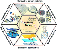
Lithium sulfur (Li–S) batteries have a high theoretical specific capacity (1675 mA h g−1) and energy density (2600 W h kg−1), possessing high potential as next-generation rechargeable batteries for long-distance transportation and large grid applications. Sulfurized polyacrylonitrile (SPAN) is known as an alternative sulfur cathode material for practical application in Li–S batteries, because of its capability of completely eradicating the shuttle of lithium polysulfides in comparison with elemental sulfur cathodes. It can be synthesized by simply heating polyacrylonitrile (PAN) and sulfur powder under the protection of an inert atmosphere and has good compatibility with carbonate-based electrolytes that are commonly used in Li-ion batteries, as well as adaptability to the manufacturing processes of current lithium-ion (Li-ion) batteries. In the past few decades, SPAN has been widely investigated with respect to its chemical structure, redox reaction and electrochemical performance. Thus, it is of great interest to thoroughly summarize the recent progress in engineering SPAN material for practical application in Li–S batteries. This review aims to describe the achievements in this promising material and gives a comprehensive overview in terms of structures, mechanisms and performances. The relationship between the cell performance between the strategies applied and the cell performance was statistically analyzed on the basis of metadata from the literature, which could give the research direction and clues for the further study. Challenges and possible directions are also discussed to shed light on its implementation in large-scale commercial production in the future.


image file: d1ta03300j-p1.tif

Xiaohui Zhao

Xiaohui Zhao received her bachelor's and master's degrees in automation control from Shandong University and Tongji University, China. She completed her second master's degree and PhD in chemical engineering at Gyeongsang National University, Korea. She joined Soochow University as an associate professor in 2016. Her research focuses on hybrid and flexible electrode nanomaterials and high energy density rechargeable batteries, including lithium–sulfur and metal–air batteries.

image file: d1ta03300j-p2.tif

Zhao Deng

Zhao Deng received his bachelor's and master's degree in chemical engineering from Shanghai Jiao Tong University, and his PhD in analytical chemistry from the University of California, Davis. He worked as a research associate at the Center for Nanoscale Science and Technology (CNST) at the National Institute of Science and Technology (NIST) after graduation. Before joining Soochow University as a full professor in 2016, he had worked in the oil & gas industry for about 5 years in the United States, serving as a senior scientist in companies including Halliburton and Afton Chemical Corporation. His current research interests include wearable energy solutions, metal–air batteries, and in situ characterization of electrode processes.


1. Introduction

With the advances in solar, wind and tide energy, an urgent demand is to develop efficient storage devices for clean energy. Lithium ion (Li-ion) batteries have witnessed application in most energy storage areas, but their energy densities are close to the ceiling value and hard to efficiently power larger grids.1,2 The prevailing applications of small-scale electronic devices and electric vehicles place even more stringent requirements on sustainability, low cost and high energy/power density of energy storage devices. The emergence of lithium sulfur (Li–S) batteries spotlights the development of this promising energy storage with high energy density (1675 mA h g−1) and energy density (2600 W h kg−1) far beyond the state-of-the-art Li-ion batteries.3,4 Naturally abundant sulfur is recognized as the most promising candidate owing to its environmentally benign and cost-effective properties. In the reduction of elemental sulfur, the final Li2S2/Li2S product is in a solid form, whereas lithium polysulfide (Li2Sn, n = 4–8) intermediates are soluble in ether-based electrolytes.5 This obstinate dissolution upon repeated redox reactions keeps Li–S batteries from practical application, as it results in the increase of electrolyte viscosity, active material loss, rapid capacity decay and poor cycle stability. Moreover, the sedimentary Li2S2/Li2S on the surface of lithium anodes also causes safety problems associated with surface erosion and pulverization. To address them, many great endeavors have been made in designing porous sulfur–carbon composite materials, modifying separators, developing new binders and electrolytes, creating catalytically active sites and protecting lithium anodes.6–9 However, the commercialization of Li–S batteries is still facing huge challenges concerning active material utilization, long cycle stability and safety concerns of lithium anodes.10

Unique sulfurized polyacrylonitrile (SPAN) has attracted chemical engineers’ attention because of its high active material utilization with almost 100% coulombic efficiency, excellent reversibility and cycle stability in the manipulation of Li–S batteries.11 SPAN can be simply synthesized via vulcanization of polyacrylonitrile (PAN) with sulfur, by which the –CN groups in the PAN polymer structure are cyclized as a stable conjugated polypyridine ring containing C[double bond, length as m-dash]C and C[double bond, length as m-dash]N double bonds.12 Sulfur is covalently bonded to the polymeric backbone of pyrolyzed PAN to form a stable molecular structure. The polysulfide shuttle is totally eradicated in lithium–SPAN (Li–SPAN) batteries to avoid the corrosion of the lithium anode and ensure an outstanding cycle stability, which typically present a high initial discharge capacity beyond the theoretical capacity of sulfur. Fig. 1 illustrates the distinct redox behavior of SPAN compared with pristine sulfur in its discharge/charge processes. The discharge plateau of Li–SPAN cells is a gradual slope, differing from the dual voltage plateau processes of Li–S cells. The first discharge of SPAN shows a low-voltage slope ramped to 1 V, which rises to 1.8 V in the following cycles with reduced polarization. It elucidates a solid–solid transformation upon reduction without the appearance of dissolved polysulfides. Also, SPAN has good thermal stability and flame retardancy to broaden its application within wide temperature ranges.13,14 However, the binding sites for sulfur are limited by the molecular structure of SPAN, resulting in the insufficient mass percentage of sulfur (∼40 wt%). Moreover, a great challenge also lies in the retarded redox kinetics and high polarization. To view the tremendous progress in the last few decades, a comprehensive summary is necessary to outline the development and challenges of SPAN, which would provide new insights into the manipulation of Li–SPAN batteries for practical applications in the future.


image file: d1ta03300j-f1.tif
Fig. 1 Different redox behaviors between a Li–S battery and Li–SPAN battery.

2. Chemical structures

To date, only a few possible molecular structures have been proposed to depict SPAN (Fig. 2). Initially, the polypyridine rings of PAN were recognized as the skeleton to wrap nano-scale elemental sulfur particles (molecules 1 and 2).15,16 FT-IR and Raman spectra evidenced the existence of C–S bonds in SPAN (molecule 3),17 and a model of the chemically linked sulfur on the polypyridine ring was proposed by Fanous et al. (molecule 4).18 A high initial capacity of 1750–1800 mA h g−1 was obtained, which exceeded the theoretical capacity of sulfur. The proposed molecule structure enables the interpretation of the extra capacity contribution from the conjugated conducting polymer backbones. Furthermore, the observation of C–H bonds in the elemental analysis of SPAN in molecule 5 explains the incomplete cyclization upon sulfurization.19 Given the totally different redox process of Li–SPAN cells and Li–S cells, small sulfur species (S2–3) were thus considered to be the group linked to the polypyridine ring (molecule 6).20 With the characterization of elemental analysis, X-ray photoelectron spectroscopy (XPS), electron paramagnetic resonance (EPR) and solid-state nuclear magnetism (ssNMR), molecules 7 and/or 8 with polypyridine rings connected by short S2–3 chains were widely accepted as possessing the structure of the SPAN molecule.21,22 A recent study revealed a new SPAN structure containing N–S and –N[double bond, length as m-dash]C–S bonds in addition to the C–S and S–S bonds (molecule 9),23 and the DFT calculation suggested the co-existence of pyrrolic and pyridinic rings in SPAN (molecules 10a and 10b).24 These reported molecular structures of SPAN hint at the extra capacity contribution in the initial discharge and the cleavage occurrence of C–S bonds upon repeated lithiation/delithiation processes.12,25 These nuances in the molecular structure perhaps suggest the good plasticity of SPAN and it being adaptive to its synthetic conditions; however, comprehensive molecular model remains to be generated for clear illustration.
image file: d1ta03300j-f2.tif
Fig. 2 The proposed chemical structures of SPAN in previous reports. Molecule 1,15 reproduced with permission. Copyright 2003, Wiley-VCH. Molecule 2,163,177,21 and 9,23 reproduced with permission. Copyright 2013, 2004, 2018 and 2020, respectively, Elsevier. Molecule 4,186,208,2210a and 10b,24 Copyright 2011, 2015, 2018 and 2021, respectively, American Chemical Society. Molecule 5,19 reproduced with permission. Copyright 2014, Multidisciplinary Digital Publishing Institute.

3. Redox reaction processes

Generally, pristine SPAN is reduced to form Li2S in the discharge process in Li–SPAN cells. A distinct phenomenon is that the initial discharge capacity is higher than the theoretical value of sulfur, which hints at a complicated redox reaction occurring in Li–SPAN cells. Some possible mechanisms were thus proposed to understand the lithium storage. Zhang et al. believed that SPAN underwent a reversible reaction of S–S and C–S bond cleavage to form lithium sulfide (Fig. 3a),19 although it is questionable to drive the cleavage and reformation of C–S bonds by just a sole redox reaction. To figure out the exceeding initial capacity, C[double bond, length as m-dash]N and C[double bond, length as m-dash]C double bonds in the pyridine ring were claimed to bond with lithium in the first discharge of Li–SPAN cells (Fig. 3b and c).17,21 The S–S bonds can be disrupted to form sulfur radicals and change the SPAN polymer to be in an ionic state, by which SPAN is competent for Li+ acceptance with high reactivity (Fig. 3d).22 Partial Li+ incorporated within SPAN, specifically linked with C and N atoms, fails to participate in redox cycles in the subsequent charge/discharge processes, likely causing irreversible capacity in the first discharge (Fig. 3e).26 To evidence it, S–S, C–S and N–S bonds were also observed to be broken and form Li–S, Li–N and Li–C bonds in the discharge process, while Li–N and Li–C bonds were still preserved in the recharged Li–SPAN cells (Fig. 3f).23 In addition, the first-principles molecular dynamics model and density functional theory (DFT) calculation also suggest the contribution of the incompletely stripped Li+ to irreversible capacity in the first discharge.27 A Co–N4S cluster was constructed in SPAN, resulting in a more conjugated polymeric matrix with faster charge transfer. Additionally, the crosslinking of Co centers in the molecular of SPAN provided extra binding sites for more sulfur content (Fig. 3g).28 Given that many possible redox processes have been proposed to explain the high initial capacity and cycle reversibility, it would be of great interest to minimize the capacity reduction after the discharge and maintain a high discharge voltage plateau by exquisite design of SPAN materials.
image file: d1ta03300j-f3.tif
Fig. 3 The proposed redox reaction mechanisms of SPAN in previous reports. (a) The cleavage of C–S bonds.19 Reproduced with permission. Copyright 2014, Multidisciplinary Digital Publishing Institute. (b and c) Lithium insertion mechanisms.17,21 Reproduced with permission. Copyright 2004 and 2018, Elsevier. (d) Sulfur free radical reaction.22 Reproduced with permission. Copyright 2018, American Chemical Society. (e) Pyridine ring takes lithium ions.26 Reproduced with permission. Copyright 2019, Wiley-VCH. (f) N–S–Li reaction.23 Reproduced with permission. Copyright 2020, Elsevier. (g) Co–N4S clusters.28 Reproduced with permission. Copyright 2021, Elsevier.

4. Cathode synthesis and modification

4.1 Material synthesis

The vulcanization process is affected by a series of reaction conditions due to the complex polymeric precursor. The different synthetic conditions of SPAN in previous studies result in an uncertainty in understanding its molecular structure as well as the redox reaction mechanism in the field, which are of importance in exploring the electrochemical performance of SPAN. The parameters including temperature, timespan, vapor pressure, molecular weight of PAN and sulfur content are comprehensively discussed below.
4.1.1 Synthesis temperature and timespan. The SPAN matrix can be synthesized in a wide range of sulfurization temperatures, which often imparts different merits to the polymeric matrix of PAN.13 Initially, SPAN was prepared at 280–300 °C, a temperature also for the dehydrogenation and cyclization of PAN.15 Based on the results from all previous reports listed in Table S1, a statistical analysis was performed as seen in Fig. 4 to illustrate the relationship between the annealing temperature and the initial/end capacity. Statistically, a better electrochemical performance of SPAN is mostly at 300–450 °C, and a capacity trough emerges at around 500 °C. The functionality-rich chemical environment of pyrolyzed PAN (pPAN) would provide more active sites for sulfur fixation towards higher capacity, and therefore a relatively high temperature is essential to form a conjugated backbone to bond the sulfur side chains,29 whereas the active C–S and C–N bonds are less detectable above 500 °C, which would be responsible for such a capacity fading.30,31
image file: d1ta03300j-f4.tif
Fig. 4 Statistical analysis of the temperature-dependent cell performance of SPAN. The orange and green dots indicate the specific capacity of initial and post cycling, respectively. The detailed information is available in Table S1. The edged dots are the mean of specific capacity for all the observations at according temperatures. The orange and green fitting curves represent the trends of specific capacity with temperature for initial and post cycling, respectively. The 95% confidence intervals were shadowed with color accordingly.

In comparison with temperature, the heating time has a less important effect on the binding mechanism between sulfur and PAN.16,29,31–33 Nevertheless, a critical timespan is necessary for the complete reaction between sulfur and PAN. A heating timespan of 2.5–4 h shows marginal chemical transformation in FT-IR analysis and SPANs with similar thermal properties were obtained with saturated sulfur, from which an upper limit of the sulfur content at 56 wt% was demonstrated.16 Thus, the majority of SPAN-based materials took 3–6 h to complete the formation of the SPAN matrix.

4.1.2 Vapor pressure. SPAN is usually produced within an excess sulfur atmosphere under ambient pressure. Whereas the vapor pressure that applied for fabricating SPAN materials should not be overlooked. Liu et al. studied the effect of vapor pressure on the performance of SPAN cell through operating the sulfurization process under different argon gas pressures. The morphology, chemical structure, surface area and electric conductivity are modulated by the vapor pressure. Also, tuning to an appropriate vapor pressure of 5 MPa tends to complete the cyclization of PAN with a high C/H ratio of 3[thin space (1/6-em)]:[thin space (1/6-em)]1 in SPAN.34 Thus the Li–SPAN cell delivered a high reversible discharge capacity of 1542 mA h g−1 in the second cycle. More related studies are necessary to consider the effect of vapor pressure, especially when subjected to sulfurization in sealed containers with sulfur vapor.
4.1.3 Molecular weight of PAN. Most reported SPAN materials employed PAN with an average molecular weight of 150[thin space (1/6-em)]000 g mol−1 as the precursor, which directly correlates with the conjugated chemical structure of SPAN as well as the binding sites for sulfur. It is generally perceived that PAN with a narrower molecular weight and higher structural purity would result in a better electrochemical performance of Li–SPAN cells.35 The in situ polymerization of acrylonitrile monomer with sulfur was proven to form the desired morphology and uniform structure.36,37 Adopting PAN with a molecular weight of 550[thin space (1/6-em)]000 g mol−1, a sulfur content of 55 wt% can be approached with sulfur utilization over 98%. The PAN precursor with a high molecular weight perhaps provides more space to accommodate chemically bonded sulfur and improve the interfacial resistance of SPAN.38

4.2 Sulfur content and areal loading

The mass percentage of sulfur in SPAN and sulfur loading in cathodes are directly associated with the energy density of Li–SPAN cells, which are thus recognized as significant engineering concerns. The dilemma between high sulfur content and excellent cell performance always challenges the experimental trials. Unfortunately, the inherent structure of PAN restricts the supply of enough sulfur storage sites. A confronted problem in SPAN is the limited sulfur content (∼40 wt%) and, as a consequence, the moderate energy density in Li–SPAN cells.12

Taking advantage of the facile synthesis method via heating sulfur and PAN, the sulfur content in SPAN can be easily altered. Fanous et al. used different weight ratios of PAN/sulfur from 1[thin space (1/6-em)]:[thin space (1/6-em)]3 to 1[thin space (1/6-em)]:[thin space (1/6-em)]60 to obtain SPAN with sulfur contents from 31 wt% to 44 wt%.39 Surprisingly, both SPAN prepared with a PAN/sulfur weight ratio of 1[thin space (1/6-em)]:[thin space (1/6-em)]15 and 1[thin space (1/6-em)]:[thin space (1/6-em)]60 gave the same sulfur content, indexing an upper limit of the mass percentage for sulfur that covalently bonded in SPAN. Notably, the covalently bonded sulfur provides a direct solid–solid reduction process to Li2S while the extra sulfur existed as an elemental state confined in the polymeric matrix still generates the polysulfide shuttling, thus resulting in degraded cell performance.40 Short-chain sulfur was reported to be confined in microporous carbons, and therefore the microporous carbon-encapsulated sulfur cathodes also enable working in the same carbonate-based electrolytes with SPAN.41 By virtue of such similarity, a microporous carbon-encapsulated sulfur composite was blended in SPAN fibers, by which a hybrid sulfur cathode with a total sulfur content of 52 wt% was achieved without elemental sulfur observed.42 Additionally, diphenyl guanidine was used as the vulcanization accelerator, by which the sulfur content in SPAN increased by 14% ascribed to its function in providing more sites to bond sulfur atoms upon the sulfurization process.43

The sulfur loading in the cathode exerts significant influence on the areal capacity and energy density of Li–SPAN cells. As listed in Table S1, most previous reports applied sulfur loadings of less than 3 mg cm−2. Obviously, the low sulfur content in SPAN is responsible for the limited sulfur loading. On the other hand, the low electric conductivity of SPAN requires extra conductive components and new cathode configurations to help deliver capacity. Highly conductive additives or modified current collectors beyond Al foil are critical and effective in fabricating high sulfur loading cathodes in building conductive pathways. The addition of ketjenblack, carbon nanotubes, etc. is found to increase the sulfur loading to above 4–6 mg cm−2.16,44 An ultrahigh sulfur loading of 30 mg cm−2 was obtained by casting on nickel foam,45 while graphene foam enabled a sulfur loading of 26.5 mg cm−2.46 Flexible and viscous binders also play key roles in fabricating high sulfur loading cathodes. A Se0.05S0.95PAN cathode using carboxymethyl cellulose (CMC) and styrene–butadiene rubber (SBR) binders obtained a high loading of 20–35 mg cm−2.47 Another useful strategy for improving the sulfur loading of SPAN cathodes is making freestanding films free of binders and current collectors. It aims to increase the active mass content to the maximum extent and will be discussed in the following as a separate part.

4.3 Cathode modifications

Many efficient strategies of cathode modification have been conducted to improve the electrochemical performance of Li–SPAN cells. Perhaps, the strategies can be briefly classified as augmenting conductive additives or polar accelerators, heteroatomic doping, and fabricating freestanding cathode configurations.
4.3.1 Cathode additives. Conductive carbon materials are required to improve the electric conductivity of SPAN for fast redox reactions in cells. Multiple carbonaceous additives, including carbon nanotubes,48,49 graphene,50–52 carbon fibers,53 and porous carbon particles,54,55 were harnessed to build electric conductive pathways in the SPAN matrix. With the combination of multiwalled nanotubes (MWNTs), a SPAN@MWNT composite showed a 20% increase in specific capacity over the MWNT free composite.48 In fact, the carbon additives not only improve the conductivity of SPAN cathodes but also help disperse the SPAN matrix. A graphene oxide (GO) blended composite was produced by uniformly dispersing only 4 wt% GO in in situ polymerized PAN to display a homogeneous morphology with a high sulfur content of 47 wt% (Fig. 5a), by which an initial discharge capacity of 1850 mA h g−1 and reversible capacity of 1200 mA h g−1 after 100 cycles were achieved (Fig. 5b).50
image file: d1ta03300j-f5.tif
Fig. 5 SPAN cathodes with different additives. (a) The synthesis and (b) cycle performance of SPAN with graphene oxide. Reproduced with permission.50 Copyright 2011, Royal Society of Chemistry. (c) The morphology and (d) work mechanism of SPAN with Mn0.6Ni0.4O. Reproduced with permission.56 Copyright 2013, Royal Society of Chemistry. (e) The morphology and (f) cycle performance of SPAN with NiS2. Reproduced with permission.57 Copyright 2017, Royal Society of Chemistry.

Polar metal oxides (e.g. Mg0.6Ni0.4O/SiO2) and sulfides (e.g. NiS2, CoS2, FeS, MoS2 and SeSx) have a strong affinity with sulfur and lithium sulfide.58–63 Mg0.6Ni0.4O was found to uniformly disperse in the SPAN matrix to form nanosized primary particles (Fig. 5c), which achieved higher sulfur utilization and improved the cycle stability with 1223 mA h g−1 in 100 cycles (Fig. 5d).56 NiS2 at a weight content less than 3 wt% was capable of optimizing the composite morphology in regular spherical particles. Serving as a polysulfide reduction accelerator, the NiS2–SPAN cell obtained an impressively high reversible capacity of 1533 mA h g−1 after 100 cycles at 0.2 A g−1 and good rate capacity up to 2 A g−1.57 Metal sulfides are naturally compatible additives with SPAN cathodes owing to their same synthetic process under vulcanization and synchronous electrochemical conversion upon lithiation/delithiation. A homogeneous combination of 52 wt% FeS and 48 wt% SPAN enabled a hybrid cathode to retain 91% of theoretical capacity after 500 cycles.64

Heteroatomic doping is proven to reduce the charge transfer resistance of the active material and promote the reduction of short-chain polysulfide ions.61,66–71 Besides, the dopants enable the improvement of the stability of the molecular structure and realize the excellent electrochemical performance of SPAN in both ether- and carbonate-based electrolytes. Selenium (Se) was introduced into the molecular structure of SPAN as proved by X-ray photoelectron spectroscopy (XPS) (Fig. 6a and b) and boosted the redox conversion rate with reduced polarization (Fig. 6c), by which accelerated Li+ migration in SexSPAN and suppressed polysulfide dissolution brought about 84% active material utilization and a rate capability up to 10 A g−1.65 The virtue of a tellurium (Te) eutectic accelerator was shown with a low decay rate of 0.05% per cycle in over 600 discharge/charge cycles, demonstrating its superior effect of heteroatomic doping on the improvement of the electrochemical performance of SPAN.72 Iodine (I) doping was reported to generate LiI and LiF in the cathode electrolyte interface (CEI) layer which contributed to enhancing the reaction kinetics and cell performance.73 Metals were also recommended as atomic dopants for coordination within the SPAN molecular structure. For instance, cobalt (Co) was coordinated with the pyridine rings of SPAN in an in situ transformation manner. With the aid of X-ray absorption near edge structure (XANES) and Fourier-transformed extended X-ray absorption fine structure (FT-EXAFS) analysis (Fig. 6d and e), a Co–N4S cluster was presented in the SPAN molecule. Such a metal coordination structure reinforced the charge transfer and served as a catalytic site for accelerating the redox reaction of sulfur.28 Electrochemical performance approached an initial discharge of 1865 mA h g−1 and an ultralong lifespan of 1500 cycles at 1C (Fig. 6f).


image file: d1ta03300j-f6.tif
Fig. 6 The heteroatomic doping in SPAN. (a–c) A dual-electrolyte compatible Se-doped cathode. Reproduced with permission.65 Copyright 2019. Nature Publishing Group. (d and e) The XAS spectra and (f) cycle performance of Co-doped SPAN. Reproduced with permission.28 Copyright 2021, Elsevier.

Binders are an indispensable component in fabricating electrodes, functioning to bridge the active materials with conductive carbon and current collectors. Adopting water-soluble sodium carboxymethyl cellulose (NaCMC) as a binder for the SPAN cathode, the Li–SPAN cell showed a better cycle performance of 450 cycles and a higher rate capability up to 5C compared to the cathode bonded by polyvinylidene fluoride (PVDF).74 Polyacrylic acid (PAA) enabled a SPAN cathode with good adhesion both to materials and current collectors.75 A more water-dissoluble and cost-effective binder of carbonyl-β-cyclodextrin exhibited strong bonding to electrode materials with moderate viscosity in water and wide electrochemical windows, and the Li–SPAN cell exhibited a high sulfur utilization of 92.2% and good cycle reversibility retaining 1456 mA h g−1 after 50 cycles.76 Chen et al. also investigated a flexible binder (AFB) to prepare high-load SPAN electrodes and achieved good battery performance under lean electrolytes.77

4.3.2 Freestanding cathodes. The minimization of inactive materials is also a practicable strategy as a substitute for casting electrodes to improve the sulfur loading of Li–SPAN cells. Freestanding SPAN cathode configurations are thus developed free of both a binder and current collector to increase energy density.26,78 To this end, electrospinning technology in combination with direct vulcanization is widely used for simple, effective and low-cost preparation of flexible composite SPAN materials. One solution is the use of sacrificial templates which allow forming holes in the fibers. The polymeric sacrifices such as polymethyl methacrylate (PMMA),79,80 polystyrene (PS),53,62 and polyethylene oxide (PEO)81 can decompose to produce pores during the vulcanization process and benefit the full reaction of SPAN.81

Notably, a one-pot trial of electrospinning multi-component solution containing sulfur, PAN and CNTs presented an integrated fibrous SPAN film with high porosity and electric conductivity, in which CNTs act as both the pore-forming agent and conductive pathway along the fiber (Fig. 7a).82 The vulcanization process does not destroy the morphology of PAN fibers, which can be well preserved within flexible SPAN cathodes. It is worth noting that the formation of the SPAN matrix begins from the fiber surface during the vulcanization process, and the resultant dense matrix hinders the access of the sulfur vapor, leading to incomplete SPAN formation. As such, the flexible SPAN electrode was endowed with higher discharge capacity and long-term cycle performance. A recent study reported metal organic framework (MOF) derived CoS2 anchored on the surface of SPAN–CNT fibers for improved fiber density and sulfur loading, by which a high initial areal capacity of 8.1 mA h cm−2 and sulfur loading of 5.9 mg cm−2 were achieved in a prototype pouch cell with a superior capacity of 1322 mA h g−1.58 Another attractive configuration is 3D holey graphene/SPAN aerogel (3DHG/PS),78 which greatly accelerated both ion and electron migration and successfully promoted the peak sulfur loading to 15.2 mg cm−2 and an ultralong cycle life of 1500 times with a low capacity fading rate of 0.012% per cycle (Fig. 7b).


image file: d1ta03300j-f7.tif
Fig. 7 The synthesis, morphology and cycle performances of freestanding SPAN cathodes. (a) Fibrous SPAN–CNT cathode. Reproduced with permission.82 Copyright 2019, Elsevier. (b) SPAN in graphene aerogel. Reproduced with permission.78 Copyright 2021, Wiley.

5. Electrolytes

Although the elemental sulfur dissolution is eliminated in SPAN cathodes, the kinetics of short-chain sulfur redox reactions still relies on the electrolyte composition, including lithium salts, solvents, gel polymer electrolytes (GPEs) and solid-state electrolytes (SSEs) in terms of their physical and chemical properties, which greatly affect the formation of a cathode electrolyte interphase (CEI) and solid electrolyte interface (SEI).7 In this section, the review summarizes the electrolyte formula and the cycle performance of Li–SPAN cells (Table 1).
Table 1 A summary of the electrolyte formula and the related cell performance of Li–SPAN cells
Cathode Electrolyte Voltage 1st Discharge capacity After cycles Ref.
S@pPAN 1 M LiODFB EC/DMC/FEC (4.5[thin space (1/6-em)]:[thin space (1/6-em)]4.5[thin space (1/6-em)]:[thin space (1/6-em)]1) 1–3 V 1875 mA h g−1, 1C 1246 mA h g−1, 1100th, 1C 87
SPAN 1 M LiPF6 EC/DMC/EMC (1[thin space (1/6-em)]:[thin space (1/6-em)]1:1) + 1 wt% LiBOB 1–3 V 1778 mA h g−1, 0.25C 1106 mA h g−1, 100th, 0.25C 86
SPAN 1 M LiPF6 EC/DEC (1[thin space (1/6-em)]:[thin space (1/6-em)]1) 1–3 V 895.6 mA h g−1, 0.25 mA cm−2 700 mA h g−1, 80th, 110 mA g−1 83
Se0.06SPAN 1 M LiTFSI DOL/DME (1[thin space (1/6-em)]:[thin space (1/6-em)]1) + 2 wt% LiNO3 1–3 V 1680 mA h g−1, 0.2 A g−1 881 mA h g−1, 800th, 0.4 A g−1 65
SPAN/CB 5 M LiTFSI DOL/DME (1[thin space (1/6-em)]:[thin space (1/6-em)]1) 3 M LiTFSI DOL/TEGDME (1[thin space (1/6-em)]:[thin space (1/6-em)]1) 1.5–3 V 1743 mA h g−1, 100 mA g−1 880 mA h g−1, 50th, 100 mA g−1 40
SPAN 4 M LiTFSI DOL/DME (1[thin space (1/6-em)]:[thin space (1/6-em)]1) + 0.5 M LiNO3 1–3 V 2050 mA h g−1, 0.12C 1190 mA h g−1, 100th, 0.1 A g−1 88
S@pPAN 1 M LiPF6 FEC/DMC (1[thin space (1/6-em)]:[thin space (1/6-em)]1) 1–3 V 1950 mA h g−1, 0.1C 1261 mA h g−1, 4000th, 6C 89
SPAN 1 M LiPF6 EC/EMC (1[thin space (1/6-em)]:[thin space (1/6-em)]1) + 11 wt% DMMP 1–3 V 1740 mA h g−1, 0.1C 1320 mA h g−1, 50th, 0.1C 90
S@PAN 1 M LiPF6 EC/DMC/EMC (1[thin space (1/6-em)]:[thin space (1/6-em)]1[thin space (1/6-em)]:[thin space (1/6-em)]1) + 25 vol%FEC–0.1 M KNO3 1–3 V 1625 mA h g−1, 0.1 A g−1 1479 mA h g−1, 100th, 0.1 A g−1 91
SPAN 1 M LiPF6 EC/DEC (1[thin space (1/6-em)]:[thin space (1/6-em)]1) + 5 wt% FEC 1–3 V 1530 mA h g−1, 0.5C 1478 mA h g−1, 100th, 0.5C 75
pPAN@S 1 M LiPF6 EC/DMC (1[thin space (1/6-em)]:[thin space (1/6-em)]1) + 10 wt% TTFP 1–3 V 2000 mA h g−1, 0.1C 1300 mA h g−1, 150th, 0.1C 92
SPAN 1 M LiBOB TEP/FEC (7[thin space (1/6-em)]:[thin space (1/6-em)]3) 1–3 V 2100 mA h g−1, 1C 1050 mA h g−1, 1000th, 1C 93
SPAN 1 M LiPF6 EC/DMC (1[thin space (1/6-em)]:[thin space (1/6-em)]1) + 5 wt% TPPi 1–3 V 1800 mA h g−1, 0.5C 1380 mA h g−1, 40th, 0.1C 94
S@pPAN 1 M LiPF6 EC/DMC (1[thin space (1/6-em)]:[thin space (1/6-em)]1) + 1 wt%TMSP–2 wt%VC 1–3 V 1830 mA h g−1, 1C 1243 mA h g−1, 800th, 1C 95
S@pPAN 1.1 M LiFSI TEP/TTE (1[thin space (1/6-em)]:[thin space (1/6-em)]3) 1–3 V 1900 mA h g−1, 0.5C 795 mA h g−1, 1000th, 0.5C 96
SPAN 1 M LiPF6 EC/DMC/DEC (1[thin space (1/6-em)]:[thin space (1/6-em)]1[thin space (1/6-em)]:[thin space (1/6-em)]1) + PMMA 1–3 V 1199.5 mA h g−1, 0.1C 975.3 mA h g−1, 50th, 0.1C 14
SPAN 1 M LiPF6 EC/DMC (1[thin space (1/6-em)]:[thin space (1/6-em)]1) + desolvated DGE 1–3 V 1951 mA h g−1, 60 mA g−1 1276 mA h g−1, 50th, 60 mA g−1 97
SPAN 1 M LiPF6 EC/DMC (1[thin space (1/6-em)]:[thin space (1/6-em)]1) + PVDF/PMMA (1[thin space (1/6-em)]:[thin space (1/6-em)]1 wt%) 1–3 V 2105 mA h g−1, 250 mA g−1 1052 mA h g−1, 100th, 1250 mA g−1 98
SPAN 1 M LiTFSI DOL/DME (1[thin space (1/6-em)]:[thin space (1/6-em)]1) + 1 wt% LiNO3 + PPC-LiTFSI@tissue paper 1–3 V 1672 mA h g−1, 0.1 A g−1 1422.1 mA h g−1, 500th, 0.1 A g−1 99
SPAN 1 M LiTFSI DOL/DME (1[thin space (1/6-em)]:[thin space (1/6-em)]1) + nano-SiO2@PPC 1–3 V 1884 mA h g−1, 0.1 A g−1 1465.6 mA h g−1, 200th, 0.1 A g−1 100
Se0.05S0.95@pPAN Li10GeP2S12 (LGPS) 1–3 V 840 mA h g−1, 0.1C 650 mA h g−1, 150th, 0.1C 101
Te0.05S0.95@pPAN@Li7P3S11 Li10GeP2S12 (LGPS) 1–3 V 1703.5 mA h g−1, 0.2C 932.9 mA h g−1, 100th, 0.2C 102
S/PAN Li3.25Ge0.25P0.75S4 (LGPS)/PEO 1–2.5 V 1772 mA h g−1, 0.1C 1183 mA h g−1, 50th, 0.2C 103
SPAN NASICON-type Li1.3Al0.3Ti1.7(PO4)3 (LATP) 1–3 V 1793 mA h g−1, 0.1C 784 mA h g−1, 120th, 0.1C 104


5.1 Li salts and alternatives

A Li salt as an indispensable component plays a significant role in ion conduction and SEI formation. Lithium hexafluorophosphate (LiPF6),83 LiTFSI,84 LiFSI,85 lithium bis(oxalate) borate (LiBOB),86 and lithium difluoro(oxalato)borate (LiODFB)87 have been investigated by modulating constituents and concentration within the interior environment of Li–SPAN cells. 1 wt% LiBOB is sufficient to form a protection layer for an increased capacity retention of SPAN over 100 cycles.86 A newly designed electrolyte of 1 M LiODFB/EC–DMC–FEC for Li–SPAN cells showed a high ionic conductivity (7.2 mS cm−1) and a wide electrochemical window (>5.5 V vs. Li/Li+) with superior compatibility with electrodes of Li and SPAN, by which the cycle life of Li–SPAN cells lasted up to 1000 times with a high capacity retention of 89%.

5.2 Electrolyte solvents and additives

Carbonate-based electrolytes such as ethylene carbonate (EC), dimethyl carbonate (DMC) and ethylmethyl carbonate (EMC) commonly used in Li-ion batteries can be adopted to Li–SPAN cells. However, an EC-based electrolyte is reported to elicit side reactions with sulfur species and deteriorate the cycle performance of SPAN.7 Fortunately, fluoroethylene carbonate (FEC) was reported to stabilize SEI formation and modulate the growth of lithium dendrites.85 By employing the LiPF6/FEC–DMC electrolyte, an uppermost lifespan of 4000 cycles at 6C with up to 96.3% capacity maintenance was achieved (Fig. 8a).89 This EC electrolyte also enabled to tolerate high capacity and rate capability (up to 30C), demonstrating superior compatibility of the FEC-based electrolyte with SPAN cathodes (Fig. 8b). The FEC-based electrolyte was beneficial to provide a LiF-rich coating on both the cathode and anode for uniform lithium deposition, and consequently display longer lifespan for Li–SPAN cells than an EC-based electrolyte (Fig. 8c and d).
image file: d1ta03300j-f8.tif
Fig. 8 FEC-based electrolyte for ultralong lifespan Li–SPAN batteries. (a) A 4000-round cycle performance and (b) high-rate capability up to 30C. (c) The function of the FEC-based electrolyte and (d) the performance comparison between FEC-based and EC-based electrolytes. Reproduced with permission.89 Copyright 2018, Elsevier.

Dimethyl ether (DME) combined with 1,3-dioxolane (DOL) is the most common solvent used in Li–S batteries. An ether-based electrolyte, using dibutyl ether (DBE) with a high concentration of 4 M lithium bis(fluorosulfonyl) imide (LiFSI), was used in Li–SPAN cells and enabled a high coulombic efficiency (99.2%) and smooth Li deposition.105 A different recipe with lithium bis(trifluoromethanesulfonyl) imide (LiTFSI) and lithium nitrate (LiNO3) as the co-salts showed a stable SEI layer and a crystalline CEI containing LiF and LiNO2 on the surface of SPAN, which allowed a much more stable delivery of the lithium anode.88 Compared to carbonate-based electrolytes, ether-based electrolytes tend to induce polysulfide dissolution and degrade the electrochemical performance. A breakthrough is to coordinate this electrolyte with a Se-doped SPAN cathode, which presented fast Li–S kinetics without sulfur loss via polysulfide dissolution and attractive rate capability and cycling stability.65 A new formula 1.8 M LiFSI in diethyl ether/bis(2,2,2-trifluoroethyl)ether (DEE/BTFE) endowed an enhanced charge rate and ultrahigh average coulombic efficiency of 99.37% with a long lifespan of 1200 cycles.106

The electrolyte additives are known to improve the electrochemical performance of lithium rechargeable batteries. Multifunctional electrolyte additives of FEC and KNO3 were reported to form a hybrid SEI layer consisting of LiF and LixNOy and meanwhile K+ ions exerted a self-healing electrostatic shield that efficiently suppresses the growth of lithium dendrites.91 Wang and coworkers designed a series of phosphorus (P)/boron (B)-containing electrolyte additives as a flame retardant to alleviate the safety concerns of Li–SPAN batteries, including dimethyl methyl phosphonate (DMMP),90 triphenyl phosphite (TPPi),94 tris(2,2,2trifluoroethyl) phosphite (TTFP),92 tris(trimethylsilyl) phosphite (TMSP),95 triethyl phosphate (TEP)93 and tris(trimethylsilyl)borate (TMSB).107 The use of these additives extends the engineers' recipes to develop novel electrolytes for lithium protection as well as promotion of the electrochemical performance of Li–SPAN batteries.

5.3 GPEs and SSEs

The GPE is attractive as a separator substitute in lithium rechargeable batteries owing to its properties of high ionic conductivity, electrolyte uptake and electrode compatibility.97,100 A GPE based on poly(vinylidene fluoride-co-hexafluoropropylene)/PMMA/montmorillonite nano clay (PVDF-HFP/PMMA/MMT) was fabricated for Li–SPAN cells and delivered a reversible capacity of 1071 mA h g−1 after 100 cycles.98 A multifunctional SiO2 filler is able to promote the ionic conductivity and interfacial stability to SPAN cathodes. The nano-SiO2-embedding endowed a poly(propylene carbonate) (PPC) based GPE with an enhanced cell performance of 85% capacity retention after 500 cycles.99 Interestingly, the synergic effect of SPAN and the GPE with a carbonate-based electrolyte allowed the cells to work at high temperature (60 °C), realizing the anticipated application of SPAN-based cells under an extreme environment.14

Solid-state lithium rechargeable batteries would be of the greatest interest with respect to safety concerns,104 although the use of SSEs causes degraded specific capacity and rate capability due to the solid–solid interfacial hindrances. Li10GeP2S12 (LGPS) has high ionic conductivity and good compatibility with sulfur. An initial capacity of 840 mA h g−1 was gained in the cells with this electrolyte and Se-doped SPAN cathodes.101 A similar synergic effect was also observed in a multiple functionalized Te0.05S0.95@pPAN@Li7P3S11 composite cathode, delivering a reversible capacity of 665.3 mA h g−1 after 500 cycles at 0.3C and exhibiting promoted reaction kinetics and a conformable interface between the electrode and SSE.102 Besides, introducing PEO, a polymer plasticizer, enabled the further improvement of the interfacial wettability.103

6. Anodes

The safety concerns of lithium anodes in Li–SPAN batteries provoked tremendous efforts towards protecting the lithium surface, constructing 3D anodes, and exploring substitutes to lithium anodes.45,108 The prolonged cycle life evidences the feasibility and superiority of anode modification strategies in suppressing the growth of lithium dendrites and avoiding the pulverization upon repeated redox cycles.109

2D reduced graphene oxide (rGO) was coated on the surface of the lithium anode to form a mosaic morphology full of cracking gaps, through which Li+ was able to transfer freely with smooth plating and stripping. This protected lithium anode was coupled with SPAN cathodes to deliver a reversible capacity of 1200 mA h g−1 for 1000 cycles at 1C.110 Li-based alloys (e.g. Li–Al, Li–Au and Li–Si) were also prepared in replacement of the ambient unstable lithium metal to assemble a Li-ion-sulfur full cell with enhanced capacity reversibility.111–113 A full cell with SiOx/C as the anode and prelithiated SPAN cathode showed a highly reversible capacity of 616 mA h g−1 at a voltage plateau of 1.6 V.114 3D composite cathodes were fabricated by pressing and heating a mixture of SPAN, MgO and lithium powder, in which an interface rich in Li3N and Li2S appeared on the surface of lithium (Fig. 9a). The hybrid framework demonstrated a fast ion transfer and suppressed lithium dendrite growth, enabling the inhibition of the volume fluctuations during the cycle processes for higher lithium activity and capability. A superb cell performance compared to the bare lithium anode was delivered for 500 cycles without great capacity fading (Fig. 9b).115 Based on the observation of lithium dendrites, a denser and regular deposit was shown, revealing a stable lithium plating and stripping process (Fig. 9c and d). An ultrathick lithium metal anode was also reconfigured via overlithiating SPAN to provide a Li2S-rich SEI.47 When paired with a high sulfur loading SPAN cathode (5 mg cm−2) and a lean electrolyte, the full cell with such an anode was able to run for 400 cycles at a low capacity decay, exhibiting promising prospects in the advancement of practical Li–S batteries.


image file: d1ta03300j-f9.tif
Fig. 9 A superb 3D composite lithium metal anode prepared by in situ lithiation of SPAN as a soft framework. (a) The schematic illustration of the formation of the hybrid interface, (b) a comparison of the 500-round cycle performance between the composite Li and bare Li, (c and d) the cross-sectional images of lithium dendrite growth and (e) the graphical diagram of the lithium deposition. Reproduced with permission.115 Copyright 2020, Elsevier.

Considering the reaction mechanism of SPAN in carbonate-based electrolytes as well as its affinity to lithium, a new configuration using SPAN as the anode for Li-ion batteries with LiMn2O4 (LMO) as the cathode exhibited an initial capacity of 1378 mA h g−1 at 0.1C and retained 90.8% after 150 cycles.116 Further modification of phosphorus doping on the lithiophilic matrix of SPAN led to a decrease of the voltage plateau of SPAN, and an increase in energy density for Li-ion batteries.71,117 A synthesized hybrid P–SPAN anode was designed to improve the conductivity and relieve the huge volume expansion by introducing P–S bonds.67 These strategies are effective alternatives for deposition and homogeneous distribution of lithium towards robust cells with high safety, high energy density and fastened reaction kinetics.47,115,116,118–120

7. Conclusions and outlook

The inherent merits of SPAN such as environmental benignity and low cost make it an attractive energy storage material with great research interest and wide application prospects. With SPAN as a promising cathode material, Li–SPAN cells exhibit superhigh capacity, outstanding reversibility and prolonged cycle stability compared to traditional Li–S batteries. Therefore, a comprehensive summary of SPAN should contribute to the fundamental understanding of the relationship between material modification strategies and electrochemical properties. In this review, the concerns on the development of SPAN cathode materials for Li–S batteries were summarized and discussed in terms of organic chemical structures, redox reactions and advances in cell performances with respect to cathode synthesis, electrolyte optimization and anode protection.

Nevertheless, the adoption of the SPAN cathode is challenging due to its unknown chemical structure and redox reaction mechanism. Great efforts have been involved to unfold the puzzles of the sulfur binding manner within the pyridine rings of pPAN, as well as the capacity contribution in the initial discharge and the lithiation/delithiation process involving the cleavage and reformation of C–S bonds. However, the current achievements regarding the understanding of SPAN are still in their infancy, and much more elaborate investigations are yet to be carried out. Many in situ or ex situ examination technologies such as X-ray absorption spectroscopy (XAS), ssNMR, XPS, time-of-flight mass spectrometry (TOF-MS), etc., are subjected to organic chemistry analyses, which would contribute to the discernment of the bona fide mechanism, especially the molecular change upon repeated redox reactions.

The processing temperature affords driving forces to fully vulcanize the PAN matrix with a certain sulfur content in the synthesis of SPAN. An appropriate temperature range at 300–500 °C is suggested according to the statistics based on previous reports. Besides, it is also worthy to consider the factors such as timespan and vapor pressure.

As for the cathode modification, highly smooth electronic and ionic pathways are extremely required to obtain outstanding electrochemical performances. Through the addition of multi-dimensional and extremely conductive carbon materials or polar additives, SPAN with a modified morphology and uniform dispersion endows the Li–SPAN cell with promoted sulfur utilization and rate capability. Heteroatomic doping is proven to be an effective strategy in optimizing the molecular structure and enhancing the reaction kinetics. To improve the active sulfur loading in cells, the development of freestanding SPAN cathodes would be a feasible solution by removing the binder and current collector. Four key factors associated with the electrochemical properties, namely, sulfur loading, initial discharge capacity, retained discharge capacity after long-term cycling (post-cycle capacity) and cycle lifespan, were thus extracted from reported data and are statistically evaluated in Fig. 10. The discharge capacities of the initial cycle broadly range from 1200 to 1800 mA h g−1 in most Li–SPAN cells, whereas the post-cycle capacities were preserved at 700–1300 mA h g−1 regardless of the cycle number and current rate the engineers adopted (Fig. 10a, left panel). The clear capacity gap between the initial and post-cycle remains to be overcome by developing more effective strategies. Besides, most researchers evaluate the lifespan and stability of their Li–SPAN cells within 100–200 cycles (Fig. 10a, right panel), which is probably insufficient to fairly assess their practical performance. Principal component analysis (PCA) of the reported cell performance was implemented to evaluate the contribution of different modification strategies (Fig. 10b). The PCA plot shows that a similar improvement can be gained by modifying the cathode additive, elemental doping, and adopting a freestanding cathode, while electrolyte engineering also exerts a significant effect on the electrochemical performance of SPAN. The detailed cell performances via these four modification strategies were evaluated by the radar plots in Fig. 10c. They all improve cell capacity, while the cycle life is still the key concern to upgrade in the future. Because of the remarkable influence of the electrolyte on both capacity and cycle life, a combined approach of two or more strategies would further promote the Li–SPAN cell performances in terms of sulfur utilization, cycle stability and rate capability in virtue of their synergic effect.


image file: d1ta03300j-f10.tif
Fig. 10 Statistics of the reported performance of Li–SPAN cells upon different modification strategies. (a) Violin plot of initial and post-discharge capacity and cycle life. The boxes and stretched lines represent the discharge capacity and cycle counts at quantile Q1–Q3 and 5–95%, respectively. Their distribution is fitted with a lognormal curve. (b) PCA plot of modification strategies. The PCA analysis can explain 68.4% of observations. The observed cell performance can be generally clustered according to modification strategies. (c) Radar plots of performance parameters upon modification strategies. Each parameter is normalized to the reported maximum. The “max”, “median” and “min” represent the maximum, median and minimum parameters for each cluster.

The binder and electrolyte are generally recognized as essential components in Li–SPAN cells, which ensure the structural stability of the cathode and ionic conduction in the process of redox reactions. Some novel flame-retardant electrolyte additives, GPEs and SSEs can alleviate the safety concerns. Besides, ether-based electrolytes are favorably compatible with the lithium surface, while carbonate-based electrolytes afford much higher capacity with a long lifespan for Li–SPAN cells. The structural stability of SPAN in these electrolytes, nevertheless, needs to be extensively studied in the future. Besides, novel redox mediators need to be explored in order to better the redox reaction of SPAN.121 Last but not least, the development of full cell configurations is highly required to render Li-SPAN cells with high energy density, in which important parameters such as high sulfur loading, low electrolyte/sulfur ratio and novel lithium anodes without dendrite growth are worthy of intensive investigation.

Conclusively, although progress has been made in the development of highly efficient SPAN cathodes, the establishment of low-cost manufacturing with a prolonged cycle life for Li–SPAN batteries is still challenging. Continuous endeavor on both material synthesis and cell engineering would surely make the application of promising SPAN based Li–S batteries a reality, hopefully in the nearest future.

Conflicts of interest

There are no conflicts to declare.

Acknowledgements

This work was supported by the National Natural Science Foundation of China (No. 21805201 and 21878198), the China Postdoctoral Science Foundation (No. 2018T110544 and 2017M611899) and the Key Technology Initiative of Suzhou Municipal Science and Technology Bureau (SYG201748). We also acknowledge the support by the Suzhou Key Laboratory for Advanced Carbon Materials and Wearable Energy Technologies. Wang C. also acknowledges a project funded by the Priority Academic Program Development of Jiangsu Higher Education Institutions (PAPD).

References

  1. P. G. Bruce, S. A. Freunberger, L. J. Hardwick and J. M. Tarascon, Nat. Mater., 2012, 11, 19–29 CrossRef CAS PubMed.
  2. M. Armand and J. M. Tarascon, Nature, 2008, 451, 652–657 CrossRef CAS PubMed.
  3. A. Manthiram, Y. Fu and Y. S. Su, Acc. Chem. Res., 2013, 46, 1125–1134 CrossRef CAS PubMed.
  4. A. Manthiram, S. H. Chung and C. Zu, Adv. Mater., 2015, 27, 1980–2006 CrossRef CAS PubMed.
  5. M. Wild, L. O'Neill, T. Zhang, R. Purkayastha, G. Minton, M. Marinescu and G. J. Offer, Energy Environ. Sci., 2015, 8, 3477–3494 RSC.
  6. M. Salama, Rosy, R. Attias, R. Yemini, Y. Gofer, D. Aurbach and M. Noked, ACS Energy Lett., 2019, 4, 436–446 CrossRef CAS.
  7. W.-J. Chen, B.-Q. Li, C.-X. Zhao, M. Zhao, T.-Q. Yuan, R.-C. Sun, J.-Q. Huang and Q. Zhang, Angew. Chem., Int. Ed., 2020, 59, 10732–10745 CrossRef CAS PubMed.
  8. S. Z. Huang, Z. H. Wang, Y. V. Lim, Y. Wang, Y. Li, D. H. Zhang and H. Y. Yang, Adv. Energy Mater., 2021, 11, 2003689 CrossRef CAS.
  9. A. Fu, C. Wang, F. Pei, J. Cui, X. Fang and N. Zheng, Small, 2019, 15, e1804786 CrossRef PubMed.
  10. T. Liu, H. Hu, X. Ding, H. Yuan, C. Jin, J. Nai, Y. Liu, Y. Wang, Y. Wan and X. Tao, Energy Storage Materials, 2020, 30, 346–366 CrossRef.
  11. J. L. Wang, J. Yang, J. Y. Xie and N. X. Xu, Adv. Mater., 2002, 14, 963–965 CrossRef CAS.
  12. H. Yang, J. Chen, J. Yang and J. Wang, Angew. Chem., Int. Ed., 2020, 59, 7306–7318 CrossRef CAS PubMed.
  13. X. U. Yu, J. Y. Xie, Y. Li, H. J. Huang, C. Y. Lai and K. Wang, J. Power Sources, 2005, 146, 335–339 CrossRef CAS.
  14. Y. Liu, D. Yang, W. Yan, Q. Huang, Y. Zhu, L. Fu and Y. Wu, iScience, 2019, 19, 316–325 CrossRef CAS PubMed.
  15. J. L. Wang, J. Yang, C. R. Wan, K. Du, J. Y. Xie and N. X. Xu, Adv. Funct. Mater., 2003, 13, 487–492 CrossRef CAS.
  16. T. N. L. Doan, M. Ghaznavi, Y. Zhao, Y. G. Zhang, A. Konarov, M. Sadhu, R. Tangirala and P. Chen, J. Power Sources, 2013, 241, 61–69 CrossRef CAS.
  17. X. G. Yu, J. Y. Xie, J. Yang, H. J. Huang, K. Wang and Z. S. Wen, J. Electroanal. Chem., 2004, 573, 121–128 CAS.
  18. J. Fanous, M. Wegner, J. Grimminger, A. Andresen and M. R. Buchmeiser, Chem. Mater., 2011, 23, 5024–5028 CrossRef CAS.
  19. S. S. Zhang, Energies, 2014, 7, 4588–4600 CrossRef.
  20. S. Wei, L. Ma, K. E. Hendrickson, Z. Tu and L. A. Archer, J. Am. Chem. Soc., 2015, 137, 12143–12152 CrossRef CAS.
  21. Z. Q. Jin, Y. G. Liu, W. K. Wang, A. B. Wang, B. W. Hu, M. Shen, T. Gao, P. C. Zhao and Y. S. Yang, Energy Storage Materials, 2018, 14, 272–278 CrossRef.
  22. W. X. Wang, Z. Cao, G. A. Elia, Y. Q. Wu, W. Wahyudi, E. Abou-Hamad, A. H. Emwas, L. Cavallo, L. J. Li and J. Ming, ACS Energy Lett., 2018, 3, 2899–2907 CrossRef CAS.
  23. M. A. Weret, C. F. J. Kuo, T. S. Zeleke, T. T. Beyene, M. C. Tsai, C. J. Huang, G. B. Berhe, W. N. Su and B. J. Hwang, Energy Storage Materials, 2020, 26, 483–493 CrossRef.
  24. C. J. Huang, K. Y. Lin, Y. C. Hsieh, W. N. Su, C. H. Wang, G. Brunklaus, M. Winter, J. C. Jiang and B. J. Hwang, ACS Appl. Mater. Interfaces, 2021, 13, 14230–14238 CrossRef CAS PubMed.
  25. C.-J. Huang, J.-H. Cheng, W.-N. Su, P. Partovi-Azar, L.-Y. Kuo, M.-C. Tsai, M.-H. Lin, S. Panahian Jand, T.-S. Chan, N.-L. Wu, P. Kaghazchi, H. Dai, P. M. Bieker and B.-J. Hwang, J. Power Sources, 2021, 492, 229508 CrossRef CAS.
  26. X. F. Wang, Y. M. Qian, L. N. Wang, H. Yang, H. L. Li, Y. Zhao and T. X. Liu, Adv. Funct. Mater., 2019, 29, 1902929 CrossRef.
  27. S. Perez Beltran and P. B. Balbuena, ACS Appl. Mater. Interfaces, 2021, 13, 491–502 CrossRef CAS PubMed.
  28. A. Abdul Razzaq, G. Chen, X. Zhao, X. Yuan, J. Hu, Z. Li, Y. Chen, J. Xu, R. Shah, J. Zhong, Y. Peng and Z. Deng, J. Energy Chem., 2021, 61, 170–178 CrossRef.
  29. L. Wang, X. M. He, J. J. Li, J. Gao, J. W. Guo, C. Y. Jiang and C. R. Wan, J. Mater. Chem., 2012, 22, 22077–22081 RSC.
  30. J. Fanous, M. Wegner, J. Grimminger, M. Rolff, M. B. M. Spera, M. Tenzer and M. R. Buchmeiser, J. Mater. Chem., 2012, 22, 23240–23245 RSC.
  31. H. L. Li, W. Y. Xue, W. C. Xu, L. A. Wang and T. X. Liu, Compos. Commun., 2021, 24, 100675 CrossRef.
  32. X. M. He, L. Wang, W. H. Pu, J. G. Ren, W. Wu, C. Y. Jiang and C. R. Wan, J. Therm. Anal. Calorim., 2008, 94, 151–155 CrossRef CAS.
  33. A. L. Páez Jerez, D. M. Chemes, E. L. Sham, L. E. Davies, A. Y. Tesio and V. Flexer, ChemistrySelect, 2020, 5, 5465–5472 CrossRef.
  34. Y. Liu, W. Wang, A. Wang, Z. Jin, H. Zhao and Y. Yang, RSC Adv., 2016, 6, 106625–106630 RSC.
  35. W. H. Pu, X. M. He, L. Wang, Z. Tian, C. Y. Jiang and C. R. Wan, Ionics, 2007, 13, 273–276 CrossRef CAS.
  36. Y. G. Zhang, Y. Zhao, Z. Bakenov, A. Konarov and P. Chen, J. Power Sources, 2014, 270, 326–331 CrossRef CAS.
  37. Y. Liu, A. K. Haridas, K. K. Cho, Y. Lee and J. H. Ahn, J. Phys. Chem. C, 2017, 121, 26172–26179 CrossRef.
  38. J. Lei, J. Chen, H. Zhang, A. Naveed, J. Yang, Y. Nuli and J. Wang, ACS Appl. Mater. Interfaces, 2020, 12, 33702–33709 CrossRef CAS PubMed.
  39. J. Fanous, M. Wegner, M. B. M. Spera and M. R. Buchmeiser, J. Electrochem. Soc., 2013, 160, A1169–A1170 CrossRef CAS.
  40. Y. Z. Zhang, S. Liu, G. C. Li, G. R. Li and X. P. Gao, J. Mater. Chem. A, 2014, 2, 4652–4659 RSC.
  41. S. Xin, L. Gu, N.-H. Zhao, Y.-X. Yin, L.-J. Zhou, Y.-G. Guo and L.-J. Wan, J. Am. Chem. Soc., 2012, 134, 18510–18513 CrossRef CAS.
  42. Y. Z. Zhang, Z. Z. Wu, G. L. Pan, S. Liu and X. P. Gao, ACS Appl. Mater. Interfaces, 2017, 9, 12436–12444 CrossRef CAS PubMed.
  43. Y. Wang, Y. Shuai and K. Chen, Chem. Eng. J., 2020, 388, 124378 CrossRef CAS.
  44. W. Wei, J. L. Wang, L. J. Zhou, J. Yang, B. Schumann and Y. N. NuLi, Electrochem. Commun., 2011, 13, 399–402 CrossRef CAS.
  45. T. Zhang, H. Lu, J. Yang, Z. Xu, J. Wang, S. I. Hirano, Y. Guo and C. Liang, ACS Nano, 2020, 14, 5618–5627 CrossRef CAS PubMed.
  46. F. Liu, S. Chiluwal, A. S. Childress, C. Etteh, K. Miller, M. Washington, A. M. Rao and R. Podila, ACS Appl. Nano Mater., 2021, 4, 53–60 CrossRef CAS.
  47. Z. Jiang, H. J. Guo, Z. Zeng, Z. Han, W. Hu, R. Wen and J. Xie, ACS Nano, 2020, 14, 13784–13793 CrossRef CAS PubMed.
  48. L. C. Yin, J. L. Wang, J. Yang and Y. N. Nuli, J. Mater. Chem., 2011, 21, 6807–6810 RSC.
  49. A. Mentbayeva, A. Belgibayeva, N. Umirov, Y. G. Zhang, I. Taniguchi, I. Kurmanbayeva and Z. Bakenov, Electrochim. Acta, 2016, 217, 242–248 CrossRef CAS.
  50. L. C. Yin, J. L. Wang, F. J. Lin, J. Yang and Y. Nuli, Energy Environ. Sci., 2012, 5, 6966–6972 RSC.
  51. J. Li, K. Li, M. Q. Li, D. Gosselink, Y. G. Zhang and P. Chen, J. Power Sources, 2014, 252, 107–112 CrossRef CAS.
  52. A. Konarov, Z. Bakenov, H. Yashiro, Y. K. Sun and S. T. Myung, J. Power Sources, 2017, 355, 140–146 CrossRef CAS.
  53. Y. Liu, A. K. Haridas, Y. Lee, K. K. Cho and J. H. Ahn, Appl. Surf. Sci., 2019, 472, 135–142 CrossRef CAS.
  54. H. Sohn, M. L. Gordin, M. Regula, D. H. Kim, Y. S. Jung, J. X. Song and D. H. Wang, J. Power Sources, 2016, 302, 70–78 CrossRef CAS.
  55. C. Hu, H. Chen, Y. Shen, D. Lu, Y. Zhao, A. H. Lu, X. Wu, W. Lu and L. Chen, Nat. Commun., 2017, 8, 479 CrossRef PubMed.
  56. Y. G. Zhang, Y. Zhao, A. Yermukhambetova, Z. Bakenov and P. Chen, J. Mater. Chem. A, 2013, 1, 295–301 RSC.
  57. Y. G. Liu, W. K. Wang, A. B. Wang, Z. Q. Jin, H. L. Zhao and Y. S. Yang, J. Mater. Chem. A, 2017, 5, 22120–22124 RSC.
  58. A. A. Razzaq, X. T. Yuan, Y. J. Chen, J. P. Hu, Q. Q. Mu, Y. Ma, X. H. Zhao, L. X. Miao, J. H. Ahn, Y. Peng and Z. Deng, J. Mater. Chem. A, 2020, 8, 1298–1306 RSC.
  59. Y. He, Z. Shan, T. Tan, Z. Chen and Y. Zhang, Polymers, 2018, 10, 930 CrossRef PubMed.
  60. V. H. Pham, A. Boscoboinik, D. J. Stacchiola, E. C. Self, P. Manikandan, S. Nagarajan, Y. X. Wang, V. G. Pol, J. Nanda, E. Paek and D. Mitlin, Energy Storage Materials, 2019, 20, 71–79 CrossRef.
  61. B. He, Z. Rao, Z. Cheng, D. Liu, D. He, J. Chen, Z. Miao, L. Yuan, Z. Li and Y. Huang, Adv. Energy Mater., 2021, 11, 2003690 CrossRef CAS.
  62. Z. Li, J. Zhang, Y. Lu and X. W. D. Lou, Sci. Adv., 2018, 4, eaat1687 CrossRef PubMed.
  63. F. Luo, X. Feng, L. Zeng, L. Lin, X. Li, B. Kang, L. Xiao, Q. Chen, M. Wei and Q. Qian, Chem. Eng. J., 2021, 404, 126430 CrossRef CAS.
  64. A. K. Haridas, J. Heo, Y. Liu, H. J. Ahn, X. Zhao, Z. Deng, M. Agostini, A. Matic, K. K. Cho and J. H. Ahn, ACS Appl. Mater. Interfaces, 2019, 11, 29924–29933 CrossRef CAS PubMed.
  65. X. Chen, L. Peng, L. Wang, J. Yang, Z. Hao, J. Xiang, K. Yuan, Y. Huang, B. Shan, L. Yuan and J. Xie, Nat. Commun., 2019, 10, 1021 CrossRef PubMed.
  66. J. Guo, Z. Y. Wen, Q. S. Wang, J. Jin and G. Q. Ma, J. Mater. Chem. A, 2015, 3, 19815–19821 RSC.
  67. Y. Hu, B. Li, X. X. Jiao, C. F. Zhang, X. H. Dai and J. X. Song, Adv. Funct. Mater., 2018, 28, 1801010 CrossRef.
  68. M. Jiang, K. L. Wang, S. Gao, R. X. Wang, J. Han, J. Yan, S. J. Cheng and K. Jiang, ChemElectroChem, 2019, 6, 1365–1370 CrossRef CAS.
  69. S. Ma, P. Zuo, H. Zhang, Z. Yu, C. Cui, M. He and G. Yin, Chem. Commun., 2019, 55, 5267–5270 RSC.
  70. S. Ma, Y. Wang, C. Fu, Y. Ma, Y. Gao, G. Yin and P. Zuo, Chem. Commun., 2020, 56, 12797–12800 RSC.
  71. A. Rabiei Baboukani, I. Khakpour, E. Adelowo, V. Drozd, W. Shang and C. Wang, Electrochim. Acta, 2020, 345, 136227 CrossRef CAS.
  72. S. P. Li, Z. L. Han, W. Hu, L. F. Peng, J. Q. Yang, L. H. Wang, Y. Y. Zhang, B. Shan and J. Xie, Nano Energy, 2019, 60, 153–161 CrossRef CAS.
  73. S. Ma, Z. Zhang, Y. Wang, Z. Yu, C. Cui, M. He, H. Huo, G. Yin and P. Zuo, Chem. Eng. J., 2021, 418, 129410 CrossRef CAS.
  74. Y. Li, Q. Zeng, I. R. Gentle and D.-W. Wang, J. Mater. Chem. A, 2017, 5, 5460–5465 RSC.
  75. H. M. Kim, J. Y. Hwang, D. Aurbach and Y. K. Sun, J. Phys. Chem. Lett., 2017, 8, 5331–5337 CrossRef CAS PubMed.
  76. J. L. Wang, Z. D. Yao, C. W. Monroe, J. Yang and Y. Nuli, Adv. Funct. Mater., 2013, 23, 1194–1201 CrossRef CAS.
  77. J. H. Chen, H. M. Zhang, H. J. Yang, J. Y. Lei, A. Naveed, J. Yang, Y. Nuli and J. L. Wang, Energy Storage Materials, 2020, 27, 307–315 CrossRef.
  78. T. Wang, Q. Zhang, J. Zhong, M. Chen, H. Deng, J. Cao, L. Wang, L. Peng, J. Zhu and B. Lu, Adv. Energy Mater., 2021, 11, 2100448 CrossRef CAS.
  79. M. Frey, R. K. Zenn, S. Warneke, K. Muller, A. Hintennach, R. E. Dinnebier and M. R. Buchmeiser, ACS Energy Lett., 2017, 2, 595–604 CrossRef CAS.
  80. K. Y. Wang, S. L. Ju, Q. L. Gao, G. L. Xia, G. F. Wang, H. X. Yan, L. X. Dong, Z. X. Yang and X. B. Yu, J. Alloys Compd., 2021, 860, 158445 CrossRef CAS.
  81. X. Y. Huang, J. Liu, Z. X. Huang, X. Ke, L. Y. Liu, N. G. Wang, J. P. Liu, Z. P. Guo, Y. Yang and Z. C. Shi, Electrochim. Acta, 2020, 333, 135493 CrossRef CAS.
  82. A. A. Razzaq, Y. Z. Yao, R. Shah, P. W. Qi, L. X. Miao, M. Z. Chen, X. H. Zhao, Y. Peng and Z. Deng, Energy Storage Materials, 2019, 16, 194–202 CrossRef.
  83. L. Wang, X. M. He, J. J. Li, M. Chen, J. Gao and C. Y. Jiang, Electrochim. Acta, 2012, 72, 114–119 CrossRef CAS.
  84. Y. Shuai, D. Wang, K. Chen, Z. Zhang, Y. Wang and J. Lou, Chem. Commun., 2019, 55, 11271–11274 RSC.
  85. S. Perez Beltran and P. B. Balbuena, J. Mater. Chem. A, 2021, 9, 7888–7902 RSC.
  86. F. Jin, C. J. Hu, C. H. Liu, Y. Zheng, H. W. Chen, Y. B. Shen and L. W. Chen, J. Electroanal. Chem., 2019, 835, 156–160 CrossRef CAS.
  87. Z. Xu, J. Wang, J. Yang, X. Miao, R. Chen, J. Qian and R. Miao, Angew. Chem., Int. Ed., 2016, 55, 10372–10375 CrossRef CAS PubMed.
  88. X. Xing, Y. J. Li, X. F. Wang, V. Petrova, H. D. Liu and P. Liu, Energy Storage Materials, 2019, 21, 474–480 CrossRef.
  89. H. J. Yang, A. Naveed, Q. Y. Li, C. Guo, J. H. Chen, J. Y. Lei, J. Yang, Y. N. Nuli and J. L. Wang, Energy Storage Materials, 2018, 15, 299–307 CrossRef.
  90. F. J. Lin, J. L. Wang, H. Jia, C. W. Monroe, J. Yang and Y. N. NuLi, J. Power Sources, 2013, 223, 18–22 CrossRef CAS.
  91. Y. Shuai, Z. Zhang, K. Chen, J. Lou and Y. Wang, Chem. Commun., 2019, 55, 2376–2379 RSC.
  92. J. Wang, F. Lin, H. Jia, J. Yang, C. W. Monroe and Y. NuLi, Angew. Chem., Int. Ed., 2014, 53, 10099–10104 CrossRef CAS PubMed.
  93. H. Yang, Q. Li, C. Guo, A. Naveed, J. Yang, Y. Nuli and J. Wang, Chem. Commun., 2018, 54, 4132–4135 RSC.
  94. H. Jia, J. Wang, F. Lin, C. W. Monroe, J. Yang and Y. NuLi, Chem. Commun., 2014, 50, 7011–7013 RSC.
  95. Q. Li, H. Yang, A. Naveed, C. Guo, J. Yang, Y. Nuli and J. Wang, Energy Storage Materials, 2018, 14, 75–81 CrossRef.
  96. H. Yang, C. Guo, J. Chen, A. Naveed, J. Yang, Y. Nuli and J. Wang, Angew. Chem., Int. Ed., 2019, 58, 791–795 CrossRef CAS PubMed.
  97. B. R. Wu, Q. Liu, D. B. Mu, Y. H. Ren, Y. Li, L. Wang, H. L. Xu and F. Wu, J. Phys. Chem. C, 2014, 118, 28369–28376 CrossRef CAS.
  98. Y. Zhang, Y. Zhao, Z. Bakenov, D. Gosselink and P. Chen, J. Solid State Electrochem., 2014, 18, 1111–1116 CrossRef CAS.
  99. H. Huang, F. Ding, H. Zhong, H. Li, W. Zhang, X. Liu and Q. Xu, J. Mater. Chem. A, 2018, 6, 9539–9549 RSC.
  100. H. Huang, C. Zhao, F. Ding, H. Li, S. Zhang, X. Liu and Q. Xu, Int. J. Energy Res., 2020, 44, 10295–10306 CrossRef CAS.
  101. Y. Y. Zhang, Y. L. Sun, L. F. Peng, J. Q. Yang, H. H. Jia, Z. R. Zhang, B. Shan and J. Xie, Energy Storage Materials, 2019, 21, 287–296 CrossRef.
  102. W. Zhang, Y. Zhang, L. Peng, S. Li, X. Wang, S. Cheng and J. Xie, Nano Energy, 2020, 76, 105083 CrossRef CAS.
  103. M. Li, J. E. Frerichs, M. Kolek, W. Sun, D. Zhou, C. J. Huang, B. J. Hwang, M. R. Hansen, M. Winter and P. Bieker, Adv. Funct. Mater., 2020, 30, 1910123 CrossRef CAS.
  104. Y. Wang, G. X. Wang, P. G. He, J. K. Hu, J. H. Jiang and L. Z. Fan, Chem. Eng. J., 2020, 393, 124705 CrossRef CAS.
  105. J. Zhou, Y. Guo, C. Liang, L. Cao, H. Pan, J. Yang and J. Wang, Chem. Commun., 2018, 54, 5478–5481 RSC.
  106. H. Liu, J. Holoubek, H. Zhou, A. Chen, N. Chang, Z. Wu, S. Yu, Q. Yan, X. Xing, Y. Li, T. A. Pascal and P. Liu, Mater. Today, 2021, 42, 17–28 CrossRef CAS.
  107. L. Wang, Q. Li, H. Yang, J. Yang, Y. Nuli and J. Wang, Chem. Commun., 2016, 52, 14430–14433 RSC.
  108. Z. Dai, M. Wang, Y. Zhang, B. Wang, H. Luo, X. Zhang, Q. Wang, Y. Zhang and H. Wu, Chem, 2020, 26, 8784–8793 CrossRef CAS.
  109. Y. Shuai, B. Zhang, X. Ding, J. Lou, Y. Wang, S. Y. Chen and K. H. Chen, Energy Technol., 2020, 8, 1901287 CrossRef CAS.
  110. Y. Yao, X. Zhao, A. A. Razzaq, Y. Gu, X. Yuan, R. Shah, Y. Lian, J. Lei, Q. Mu, Y. Ma, Y. Peng, Z. Deng and Z. Liu, J. Mater. Chem. A, 2019, 7, 12214–12224 RSC.
  111. J. Sun, Q. C. Zeng, R. T. Lv, W. Lv, Q. H. Yang, R. Amal and D. W. Wang, Energy Storage Materials, 2018, 15, 209–217 CrossRef.
  112. Y. Chen, X. Ke, Y. Cheng, M. Fan, W. Wu, X. Huang, Y. Liang, Y. Zhong, Z. Ao, Y. Lai, G. Wang and Z. Shi, Energy Storage Materials, 2020, 26, 56–64 CrossRef.
  113. T. Zhang, M. Hong, J. Yang, Z. Xu, J. Wang, Y. Guo and C. Liang, Chem. Sci., 2018, 9, 8829–8835 RSC.
  114. L. Shi, Y. Liu, W. Wang, A. Wang, Z. Jin, F. Wu and Y. Yang, J. Alloys Compd., 2017, 723, 974–982 CrossRef CAS.
  115. H. C. Lu, T. Zhang, Y. X. Kuai, J. Yang, J. L. Wang, Y. N. Nuli, Y. S. Guo and C. D. Liang, Energy Storage Materials, 2020, 33, 452–459 CrossRef.
  116. G. B. Berhe, W. N. Su, C. J. Huang, T. M. Hagos, T. T. Hagos, H. K. Bezabh, M. A. Weret, L. H. Abrha, Y. W. Yang and B. J. Hwang, J. Power Sources, 2019, 434, 126641 CrossRef CAS.
  117. Y. Wang, P. Zuo, S. Ma, B. Xie, Z. Yu and G. Yin, Chem. Commun., 2020, 56, 12857–12860 RSC.
  118. G. B. Berhe, W.-N. Su, L. H. Abrha, H. K. Bezabh, T. M. Hagos, T. T. Hagos, C.-J. Huang, N. A. Sahalie, B. A. Jote, B. Thirumalraj, D. Kurniawan, C.-H. Wang and B. J. Hwang, J. Mater. Chem. A, 2020, 8, 14043–14053 RSC.
  119. Z. Liu, S. Ma, X. Mu, R. Li, G. Yin and P. Zuo, ACS Appl. Mater. Interfaces, 2021, 13, 11985–11994 CrossRef CAS PubMed.
  120. Y. Wu, W. Wang, J. Ming, M. Li, L. Xie, X. He, J. Wang, S. Liang and Y. Wu, Adv. Funct. Mater., 2019, 29, 1805978 CrossRef.
  121. C. X. Zhao, W. J. Chen, M. Zhao, Y. W. Song, J. N. Liu, B. Q. Li, T. Yuan, C. M. Chen, Q. Zhang and J. Q. Huang, EcoMat, 2020, 3, e12066 Search PubMed.

Footnote

Electronic supplementary information (ESI) available. See DOI: 10.1039/d1ta03300j

This journal is © The Royal Society of Chemistry 2021