A high performance Li-rich β-Li2IrO3 electrode for symmetric lithium ion batteries†
Lei
Zhang
 *a,
Yuhai
Dou
b,
Mohammad
Al-Mamun
 *b and
Guowen
Meng
 *a
*a
aCentre for Catalysis and Clean Energy, Gold Coast Campus, Griffith University, Queensland 4222, Australia
bKey Laboratory of Materials Physics, Anhui Key Laboratory of Nanomaterials and Nanotechnology, Institute of Solid State Physics, HFIPS, Chinese Academy of Sciences, Hefei 230031, China. E-mail: lei.zhang@griffith.edu.au; m.al-mamun@griffith.edu.au; gwmeng@issp.ac.cn
First published on 19th April 2021
Abstract
A symmetric battery composed of a single electrode material as both the anode and cathode is a model battery configuration owing to its distinctive advantages over the existing asymmetric ones in terms of cost, production process and safety issues. However, the limited choice of suitable electrode materials limits the practical application of high-performance symmetric batteries. Herein, we report a novel Li-rich β-Li2IrO3 (LIO) symmetric electrode material with a reversible capacity of >200 mA h g−1 between 3.0 and 4.8 V (LIO-cathode) and >300 mA h g−1 between 0.1 and 3.0 V (LIO-anode), respectively. The synthesized LIO materials manifested a unique three dimensionally (3D) ordered hyperhoneycomb-like structure that endows the material with enhanced structural integrity and stability, leading to an outstanding cycle life of both the LIO-cathode and anode. Additionally, the symmetric full lithium ion battery (LIB) using LIO as both the anode and cathode exhibited a high reversible capacity of 160 mA h g−1 between 2.0 and 4.5 V with a high working potential of 3.5 V.
Introduction
A symmetric full battery consisting of an identical cathode and anode material has been regarded as an ideal battery configuration due to its advantages of easy fabrication process, low cost and better safety features compared to those of asymmetric batteries.1 In a symmetric full cell, a single material is used to fabricate both electrodes which makes the production process simpler and cost effective.2 Moreover, the underlying safety issue in traditional batteries arising from large volume changes during the charge–discharge process can be alleviated in a symmetric full cell where the cathodic volume shrinkage can be compensated for by anodic volume expansion to the same extent or vice versa, and therefore the overall cell volume remains constant.3However, the technological advancement in developing high performance symmetric batteries has been significantly hampered due to the shortfall of potential electrode materials with high working potential and good reversible capacity. So far, a number of promising symmetric electrode materials have been proposed such as titanate salt-based electrodes (O3-type Na0.8Ni0.4Ti0.6O2,4 P2-type Na0.6[Cr0.6Ti0.4]O2,5 P2-Na0.66LixMn0.5Ti0.5O2 (ref. 6) and Na0.55Mn1.4Ti0.6O4 (ref. 7)), phosphate salt-based electrodes (NASICON-type Li3V2(PO4)3,8,9 Na3Co0.5Mn0.5Ti(PO4)3,10 Na3MnTi(PO4)3,11 NaVPO4F,12 Na2VTi(PO4)3,13 Na7V4(P2O7)4(PO4),14 Na2V6O16 (ref. 15) and Na3V2(PO4)3 (ref. 16 and 17)), layered oxides (LiNi1/3Co1/3Mn1/3O2 (ref. 18 and 19)) and polymer electrodes (tetrasodium salt of 2,5-dihydroxyterephthalic acid20 and dual redox-active polyimides21). However, these existing electrode materials suffer from poor reversible capacities (<150 mA h g−1) and low working potentials (<2.5 V), resulting in a very limited energy output from the full cell. Therefore, the development of an efficient electrode with large theoretical capacity and operating potential could be of significant interest for high performance symmetric full batteries.
In 2017, a Li-rich β-Li2IrO3 polymorph was first introduced as an electrode material showing anionic redox activity.22 Different from the commercial layered oxide cathodes, such as LiCoO2, Li[Ni1/3Mn1/3Co1/3]O2 (Li-NMC) and Li-rich Li[LixNiyMnzCo1−x−y−z]O2, β-Li2IrO3 is composed of 3D edge-sharing IrO6 octahedra, leading to an unusual 3D-ordered hyperhoneycomb-like structure. Therefore, it is regarded as an extraordinary host for reversible lithiation/delithiation reactions due to this unique 3D structure which can effectively accommodate its structural fluctuation during the continuous electrochemical redox processes. Compared with 1D and 2D electrode materials, the 3D porous structure can contribute rich electronic/ionic pathways to improve the rate performance especially under high current densities. Additionally, 3D frameworks exhibit improved structural stability during continuous cycling due to the introduced porous interconnected skeleton, while the overall structural stability and integrity of 1D and 2D structured electrodes are relatively poor. Furthermore, β-Li2IrO3 can deliver a very high reversible capacity of 300 mA h g−1 between 2.0 and 4.8 V when it is used as a cathode material (LIO-cathode) in lithium ion batteries (LIBs). The high reversible capacity of the LIO-cathode is mainly the result of its stable 3D ordered Ir–O framework that maintains the structural integrity of β-Li2IrO3 even when reversibly losing all of the Li atoms after full oxidation/delithiation processes. This is a unique physico-chemical feature for 3D β-Li2IrO3 which was not identified in traditional Li-rich NMC layered oxides. However, the utilization of such attractive feature of β-Li2IrO3 electrode materials in LIBs has long been overlooked and deserves an in-depth investigation.
Like other symmetric electrodes, the Ir atom inside β-Li2IrO3 has variable oxidation states (Ir2+, Ir4+ and Ir6+) that offer electrochemical activity over a wide potential window. For example, β-Li2IrO3 may deliver a theoretical capacity of 422![[thin space (1/6-em)]](https://www.rsc.org/images/entities/char_2009.gif) mA h g−1 under a full reduction from Ir4+ to Ir0 when used as an anode (LIO-anode). Based on the dual advantages of volume tolerant 3D structure and wider potential activity, Li rich β-Li2IrO3 could be considered as a potential electrode material for symmetric LIBs. This is the first time we report LIO-based symmetric cells showing high reversible capacities of 210 and 390 mA h g−1 with outstanding cycling stability for the LIO-cathode and LIO-anode, respectively. Also, the performance of LIBs with LIO based electrodes was realized in a symmetric full cell where a reversible capacity of 160 mA h g−1 with a high working potential of 3.5 V was obtained.
mA h g−1 under a full reduction from Ir4+ to Ir0 when used as an anode (LIO-anode). Based on the dual advantages of volume tolerant 3D structure and wider potential activity, Li rich β-Li2IrO3 could be considered as a potential electrode material for symmetric LIBs. This is the first time we report LIO-based symmetric cells showing high reversible capacities of 210 and 390 mA h g−1 with outstanding cycling stability for the LIO-cathode and LIO-anode, respectively. Also, the performance of LIBs with LIO based electrodes was realized in a symmetric full cell where a reversible capacity of 160 mA h g−1 with a high working potential of 3.5 V was obtained.
Results and discussion
Structural characteristics
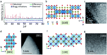
The scanning electron microscopy (SEM) images in Fig. S1a and b† indicate that β-Li2IrO3 is composed of interconnected microspheres with a uniform size distribution of about 1 μm. All the β-Li2IrO3 microspheres were found to be interconnected by a β-Li2IrO3 sheet where both the β-Li2IrO3 microspheres and β-Li2IrO3 sheet consist of aggregated β-Li2IrO3 nanoparticles, leading to a sea-island structure. We believe that the reason for the formation of this sea-island structure was mainly due to the two-step synthesis method. The original precursors were first ground into smaller sized particles during the ball-milling process. Then, the adjacent particles were automatically aggregated into microspheres and connected by extra sheet-like particles during the annealing process, resulting in the unique sea-island structure. The energy dispersive X-ray spectroscopy (EDS) mapping images in Fig. S1c and d, and Fig. S2† demonstrate the uniform elemental distribution of Ir within the material in both the sheet and microspheres, while the elemental distribution of O is mainly concentrated on the β-Li2IrO3 microspheres. Moreover, according to the transmission electron microscopy (TEM) images in Fig. S3,† the single β-Li2IrO3 nanoparticle with a diameter of about 20 nm is composed of smaller nanoparticles with size ranging from 3 to 5 nm. The Raman spectrum in Fig. S4† demonstrates the successful synthesis of β-Li2IrO3 with typical Ir–O vibrations at Eg, A1g, and B2g modes (the peaks of A1g and B2g are overlapped).23Fig. 1a shows the experimental and simulated XRD patterns (λ = 1.5406 Å) of the prepared β-Li2IrO3 with Rietveld refinement with reasonably low R-factor (6.15%) and x2 (0.9218) values, confirming its orthorhombic Fddd structure with a, b and c of 5.8903, 8.4261, and 17.7924 Å, respectively. β-Li2IrO3 is constructed on an edge-sharing IrO6 octahedron that forms a 3D framework where Li+ occupies all available octahedral positions which allows the Li migration via corrugated interconnected pathways. Fig. 1b–g show the [110], [001] and [100] high-resolution scanning transmission electron microscopy (STEM) images with their corresponding 3D frameworks along the main crystallographic axis of β-Li2IrO3. According to the [110], [001] and [100] STEM images, a high crystalline degree can be detected which confirms the single crystal structure of β-Li2IrO3.Lithium ion storage performance of LIO-based electrodes in half LIBs
Fig. 2a illustrates the charge/discharge profiles of β-Li2IrO3 at a current density of 50 mA g−1 between 3.0 and 4.8 V (used as a cathode, LIO-cathode). The staircase profiles of the LIO-cathode during the first charge/discharge can clearly be observed, corresponding to a multi-step electrochemical reaction between LIO and Li+. Additionally, such multi-step delithiation/lithiation plateaus were well maintained in the 2nd cycle, demonstrating the reversible phase evolution of the LIO-cathode. The initial charge and discharge capacities of the LIO-cathode were 250 and 210 mA h g−1, respectively, corresponding to a high initial coulombic efficiency (ICE) of 84%. The high reversible capacity indicates that the Li atoms can be mostly extracted in a reversible fashion from β-Li2IrO3 during delithiation processes (β-Li2IrO3 − 2Li ↔ IrO3). Fig. 2b shows the CV profiles of the LIO-cathode at a scan rate of 0.1 mV s−1 in the voltage range of 3.0–4.8 V. The three reversible oxidation/reduction peaks in the range of 3.0–4.0 V, 4.0–4.2 V and 4.2–4.5 V could be related to three delithiation/lithiation plateaus in Fig. 2a. As expected, these three oxidation/reduction peaks were well maintained in the subsequent cycles. However, the CV curves had a poor repeatability when the charging voltage increased over 4.6 V. We believe that this was mainly due to the decomposition of the electrolyte under high voltage. Therefore, further study of the electrolyte to maintain stable electrochemical properties under a high voltage window is necessary. The ex situ XRD results in Fig. S5† were consistent with the previous report, indicating that the orthorhombic Fddd structure of β-Li2IrO3 was maintained after the first charging platform at 4.0 V and transformed into the monoclinic C2/c structure after the second charging platform at 4.2 V.22 The relevant STEM images of the LIO-cathode at different voltages during the first charge–discharge process are provided in Fig. S6.† It can be seen that the crystal structure of the LIO-cathode was well preserved during the whole process. However, an amorphous layer at the edges of the LiO-cathode (Fig. S6d†) was observed after the first discharge process at 3.0 V, indicating the reaction with electrolyte.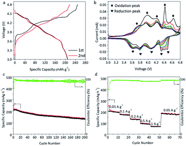 | ||
| Fig. 2 Electrochemical performance of the LIO-cathode in half cells. The charge–discharge profiles (a), CV data (b), and cycling (c) and rate performance (d) of the LIO-cathode. | ||
The cycling performance of the LIO-cathode in Fig. 2c shows a 67% retention of reversible capacity after 200 cycles, indicating its outstanding structural stability. Therefore, we believe that the 3D-ordered hyperhoneycomb-like structure has a unique capability to accommodate the gradual phase evolution of the Li-rich β-Li2IrO3 under operational conditions, leading to the improved cycle life and excellent rate performance (Fig. 2d). A high and stable capacity of about 50 mA h g−1 was achieved under a current density of 1000 mA g−1. Therefore, we presume that the rigid 3D open framework inside Li-rich β-Li2IrO3 provides fast Li ion diffusion pathways without adversely affecting its structural integrity. The interfacial charge transfer resistance (Rct) was investigated by electrochemical impedance spectroscopy (EIS) and the Nyquist plot is presented in Fig. S7.† The LiO-cathode displayed a small charge transfer resistance (Rct) of ≈160 Ω, indicating the fast transfer of ions and electrons within the LIO microstructure.
Fig. 3a shows the charge and discharge profiles of β-Li2IrO3 at a current density of 50 mA g−1 between 0.1 and 3.0 V (used as an anode, LIO-anode). Similar to the LIO-cathode, a multi-step discharge profile can also be observed during the initial lithiation process. However, the multiple discharging stages disappeared during subsequent charge–discharge processes. The discharge and charge capacities during the first cycle were about 407 and 390 mA h g−1, corresponding to an ICE of 95.8%. Fig. 3b shows the CV profiles of the LIO-anode at a scan rate of 0.1 mV s−1 in the voltage range of 0.1–3.0 V. Three main reduction peaks during the first cycle can be identified at about 1.6 V, 1.2 V and 0.8 V, consistent with the voltage profile depicted in Fig. 3a. The intensities of these redox peaks were recorded to be reduced in the following cycles. As shown in Fig. 3c, the LIO-anode demonstrates good cycling stability with a reversible capacity over 300 mA h g−1 after 300 cycles, corresponding to a high capacity retention of 77.7%. Furthermore, superior rate behavior of the LIO-anode is obtained (Fig. 3d) with a high reversible capacity of 145 and 120 mA h g−1 at 500 and 1000 mA g−1, respectively.
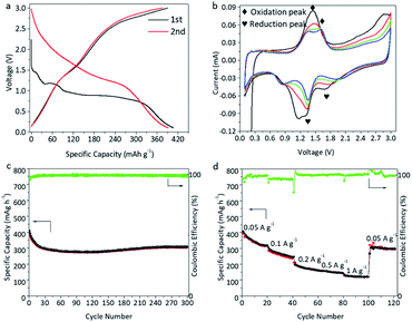 | ||
| Fig. 3 Electrochemical performance of the LIO-anode in half cells. The charge–discharge profiles (a), CV data (b), and cycling (c) and rate performance (d) of the LIO-anode. | ||
In situ Raman analysis of the LIO-anode
With the aid of in situ Raman spectroscopy, the reaction mechanism and crystal structure evolution of the LIO-anode upon lithiation/delithiation between 0.1 and 3.0 V were investigated. Fig. 4 shows the in situ Raman spectra along with the charge–discharge curves of the LIO-anode during the first cycle at 50 mA g−1. The well-defined peak located at 710 cm−1 can be assigned to typical Ir–O vibrations at B2g and A1g of β-Li2IrO3. The peak intensities of B2g and A1g were noticed to be gradually decreased with the discharge process. All the peaks disappeared after the first discharge process at 0.1 V and no peaks can be detected in the following charging process, indicating that the crystalline β-Li2IrO3 was irreversibly transformed into the amorphous LixIrOy after the first discharge process. The peak intensity changes are summarized in Fig. S8.† It decreased from 100% to 2% after the first discharge process with no recovery in the following charging process. According to the STEM image of the LIO-anode after the first discharge at 0.1 V in Fig. S9a,† the original crystal structure of β-Li2IrO3 was fully transformed into its corresponding amorphous structure. Moreover, this amorphous structure was retained after the following charging process at 3.0 V (Fig. S9b†). Therefore, it can be concluded that the β-Li2IrO3 crystal was irreversibly converted to the amorphous Li2IrO3 when used as an anode in LIBs, which is significantly different from the electrochemical behavior of the LIO-cathode.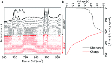 | ||
| Fig. 4 The in situ Raman results with the charge–discharge profiles of the LIO-anode during the first cycle. | ||
Lithium ion storage performance of LIO electrodes in the symmetric full LIBs
Due to the outstanding electrochemical performance of both the LIO-cathode and LIO-anode, we further created a symmetric full cell model battery based on the β-Li2IrO3 electrode. For this full cell, LIO was used as both the cathode and anode, named LIO//LIO. Fig. 5a shows the CV curves of LIO//LIO at a scan rate of 0.1 mV s−1 in the voltage range of 2.0–4.5 V. Broad redox peaks can be seen in the CV curves, corresponding to the broad slopes in the charge–discharge profiles in Fig. 5b. The working potential for this symmetric full cell is located at about 3.5 V. The initial charge and discharge capacities of LIO//LIO were 90 and 150 mA h g−1, corresponding to an ICE of 60%. However, the coulombic efficiency (CE) increased to 94% in the 2nd cycle. The cycling performance of LIO//LIO is shown in Fig. 5c where the reversible capacity was calculated to be about 93 mA g−1 after 50 cycles under a current density of 50 mA g−1, which indicates a retention of 62% reversible capacity. The LIO//LIO full cell also exhibited acceptable rate performance with reversible capacities of 50 mA h g−1 and 40 mA h g−1 under high current densities of 300 mA g−1 and 400 mA g−1, respectively. The Nyquist plot of the LIO//LIO full cell was further collected to evaluate the electrical conductivity (Fig. S10†) and the Rct for LIO//LIO was found to be about 250 Ω which is higher than that of the LIO-based half-cell.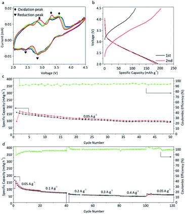 | ||
| Fig. 5 Electrochemical performance of LIO//LIO full cells. (a) CV data, (b) charge–discharge profiles, and (c) cycling and (d) rate performance of LIO//LIO full cells. | ||
To monitor the structural changes of electrode materials after continuous charge/discharge processes, SEM images of the LIO-cathode (Fig. S11†) and LIO-anode (Fig. S12†) were obtained for the LIO//LIO full cell.24,25 According to the SEM images and their relevant elemental mapping results, the original structure of β-Li2IrO3 electrodes was well maintained with a uniform Ir and O distribution. However, the surface of the LIO-anode was observed to be coated with thick SEI film, which is different from the original LIO powder.
Experimental
Fabrication of the β-Li2IrO3 electrode material
IrO2 (Sigma Aldrich) and Li2CO3 (Sigma Aldrich) with 20% excess were mixed by ball-milling for 30![[thin space (1/6-em)]](https://www.rsc.org/images/entities/char_2009.gif) min to ensure a uniform distribution of IrO2 and Li2CO3. Then, the mixture was calcined at 1000
min to ensure a uniform distribution of IrO2 and Li2CO3. Then, the mixture was calcined at 1000![[thin space (1/6-em)]](https://www.rsc.org/images/entities/char_2009.gif) °C for 86
°C for 86![[thin space (1/6-em)]](https://www.rsc.org/images/entities/char_2009.gif) h under air followed by cooling to room temperature.
h under air followed by cooling to room temperature.
Characterization
The morphologies of all the prepared samples in this work were characterized using scanning electron microscopy (SEM, JEOL 7100). High-angle annular dark-field (HAADF)-scanning transmission electron microscopy (STEM) imaging and energy dispersive X-ray spectroscopy (EDS)-STEM mapping were carried out on a JEM ARM 200. The XRD results were achieved using a Shimadzu XRD-6000 diffractometer with Cu Kα radiation (λ = 1.5418 Å). Raman spectra were obtained using a Renishaw inVia Raman system with a 532 nm excitation laser.Electrochemical tests
The electrochemical properties, such as the cycle life, rate ability and cyclic voltammetry (CV) curves, were tested using a LAND-CT-2001A battery tester and CHI660D electrochemical workstation. Coin-cell (CR2032) batteries were assembled in a SIEMENS-MBRAUN argon-filled glovebox. The electrode was composed of 70 wt% β-Li2IrO3 as an active material, 20 wt% carbon black as a conducting agent, and 10 wt% poly(vinylidene fluoride) (PVDF) as a binder, which were mixed uniformly with N-methyl pyrrolidone (NMP) as the solvent. Al and Cu foil were used as the current collector for the cathode and anode, respectively. The electrolyte was a mixture of 1.0 M LiPF6 in ethylene carbonate (EC), propylene carbonate (PC) and dimethyl carbonate (DMC) in the ratio of 1![[thin space (1/6-em)]](https://www.rsc.org/images/entities/char_2009.gif) :
:![[thin space (1/6-em)]](https://www.rsc.org/images/entities/char_2009.gif) 1
1![[thin space (1/6-em)]](https://www.rsc.org/images/entities/char_2009.gif) :
:![[thin space (1/6-em)]](https://www.rsc.org/images/entities/char_2009.gif) 3 by weight. For the symmetric full cell fabrication, the mass ratio between the cathode and anode was 2
3 by weight. For the symmetric full cell fabrication, the mass ratio between the cathode and anode was 2![[thin space (1/6-em)]](https://www.rsc.org/images/entities/char_2009.gif) :
:![[thin space (1/6-em)]](https://www.rsc.org/images/entities/char_2009.gif) 1. The capacity of the full cell was calculated based on the mass of the cathode. CV was performed using a Biologic VMP-3 electrochemical workstation between 0.1 V and 3.0 V at a scan rate of 0.1 mV s−1 for the anode, 3.0 V−4.8 V at 0.1 mV s−1 for the cathode, and 2.0 V−4.5 V at 0.1 mV s−1 for the symmetric full cell. Electrochemical impedance spectroscopy (EIS) of the fresh cells was performed in the frequency range from 0.1 Hz to 105 Hz. All the electrochemical tests were conducted at room temperature.
1. The capacity of the full cell was calculated based on the mass of the cathode. CV was performed using a Biologic VMP-3 electrochemical workstation between 0.1 V and 3.0 V at a scan rate of 0.1 mV s−1 for the anode, 3.0 V−4.8 V at 0.1 mV s−1 for the cathode, and 2.0 V−4.5 V at 0.1 mV s−1 for the symmetric full cell. Electrochemical impedance spectroscopy (EIS) of the fresh cells was performed in the frequency range from 0.1 Hz to 105 Hz. All the electrochemical tests were conducted at room temperature.
Conclusions
In conclusion, a symmetric full lithium ion battery (LIB) was fabricated using the newly proposed Li-rich β-Li2IrO3 electrodes as both the anode and cathode. A detailed analysis of the phase evolution of the β-Li2IrO3-based cathode and anode was performed by ex situ XRD and in situ Raman spectroscopy. Both the β-Li2IrO3-based cathode and anode showed outstanding electrochemical performance in the half cells. After the fabrication of symmetric full cells, a high reversible capacity (150 mA h g−1), good cycling stability (62% reversible capacity was maintained after 50 cycles) and large working potential (3.5 V) were obtained. Compared with the existing asymmetric LIBs, this symmetric design might offer improved safety with a simplified fabrication process. We believe that this work may contribute relevant knowledge and understanding for the future development of symmetric energy storage systems.Conflicts of interest
The authors declare that they have no competing interests.Acknowledgements
This work is supported by the Australian Research Council Discovery Projects (DP180103430 and DP200100965) and a 2020 Griffith University Postdoctoral Fellowship (CEE2550 LEZHA). The authors acknowledge the scientific and technical input from the Microscopy Australia node at the University of Sydney (Sydney Microscopy & Microanalysis).Notes and references
- L. Zhang, B. W. Zhang, C. R. Wang, Y. H. Dou, Q. Zhang, Y. J. Liu, H. Gao, M. Al-Mamun, W. K. Pang, Z. P. Guo, S. X. Dou and H. K. Liu, Nano Energy, 2019, 60, 432–439 Search PubMed
.
- L. Zhang, S. X. Dou, H. K. Liu, Y. H. Huang and X. L. Hu, Adv. Sci., 2016, 3, 1600115 Search PubMed
.
- C. R. Wang, L. Zhang, M. Al-Mamun, Y. H. Dou, P. R. Liu, D. W. Su, G. X. Wang, S. Q. Zhang, D. Wang and H. J. Zhao, Adv. Energy Mater., 2019, 9, 1900909 Search PubMed
.
- S. Guo, H. Yu, P. Liu, Y. Ren, T. Zhang, M. Chen, M. Ishida and H. Zhou, Energy Environ. Sci., 2015, 8, 1237–1244 Search PubMed
.
- Y. Wang, R. Xiao, Y. S. Hu, M. Avdeev and L. Chen, Nat. Commun., 2015, 6, 6954 Search PubMed
.
- F. D. Hu and X. L. Jiang, Adv. Powder Technol., 2018, 29, 1049–1053 Search PubMed
.
- G. D. Zou, B. C. Ge, H. Zhang, Q. R. Zhang, C. Fernandez, W. Li, J. Y. Huang and Q. M. Peng, J. Mater. Chem. A, 2019, 7, 7516–7525 Search PubMed
.
- E. Kobayashi, L. S. Plashnitsa, T. Doi, S. Okada and J.-i. Yamaki, Electrochem. Commun., 2010, 12, 894–896 Search PubMed
.
- Y. Kee, N. Dimov, E. Kobayashi, A. Kitajou and S. Okada, Solid State Ionics, 2015, 272, 138–143 Search PubMed
.
- H. Wang, C. Chen, C. Qian, C. Liang and Z. Lin, RSC Adv., 2017, 7, 33273–33277 Search PubMed
.
- H. C. Gao and J. B. Goodenough, Angew. Chem., 2016, 55, 12768–12772 Search PubMed
.
- C. C. Chen, T. J. Li, H. Tian, Y. B. Zou and J. C. Sun, J. Mater. Chem. A, 2019, 7, 18451–18457 Search PubMed
.
- J. Dong, G. M. Zhang, X. G. Wang, S. Zhang and C. Deng, J. Mater. Chem. A, 2017, 5, 18725–18736 Search PubMed
.
- L. B. Tang, J. H. Zhang, Z. Li, X. H. Liu, Q. J. Xu, H. M. Liu, Y. G. Wang, Y. Y. Xia and Z. F. Ma, J. Power Sources, 2020, 451, 227734 Search PubMed
.
- S. Yuan, Y. Zhao and Q. Wang, J. Alloys Compd., 2016, 688, 55–60 Search PubMed
.
- Y. Noguchi, E. Kobayashi, L. S. Plashnitsa, S. Okada and J.-i. Yamaki, Electrochim. Acta, 2013, 101, 59–65 Search PubMed
.
- X. W. Liu, X. Y. Jiang, F. P. Zhong, X. M. Feng, W. H. Chen, X. P. Ai, H. X. Yang and Y. L. Cao, ACS Appl. Mater. Interfaces, 2019, 11, 27833–27838 Search PubMed
.
- Y. S. Wang, Z. M. Feng, S. Z. Yang, C. Gagnon, V. Gariepy, D. Laul, W. Zhu, R. Veillette, M. L. Trudeau, A. Guerfi and K. Zaghib, J. Power Sources, 2018, 378, 516–521 Search PubMed
.
- Y. L. Jin, W. W. He, F. Ren, P. G. Ren and Y. L. Xu, Electrochim. Acta, 2019, 325, 134932 Search PubMed
.
- S. Wang, L. Wang, Z. Zhu, Z. Hu, Q. Zhao and J. Chen, Angew. Chem., Int. Ed. Engl., 2014, 53, 5892–5896 Search PubMed
.
- N. Casado, D. Mantione, D. Shanmukaraj and D. Mecerreyes, Chemsuschem, 2020, 13, 2464–2470 Search PubMed
.
- P. E. Pearce, A. J. Perez, G. Rousse, M. Saubanere, D. Batuk, D. Foix, E. McCalla, A. M. Abakumov, G. Van Tendeloo, M. L. Doublet and J. M. Tarascon, Nat. Mater., 2017, 16, 580 Search PubMed
.
- J. J. Gao, C. Q. Xu, S. F. Hung, W. Liu, W. Z. Cai, Z. P. Zeng, C. M. Jia, H. M. Chen, H. Xiao, J. Li, Y. Q. Huang and B. Liu, J. Am. Chem. Soc., 2019, 141, 3014–3023 Search PubMed
.
- L. Zhang, B. W. Zhang, Y. H. Dou, Y. X. Wang, M. Mamun, X. L. Hu and H. K. Liu, ACS Appl. Mater. Interfaces, 2018, 10, 20422–20428 Search PubMed
.
- L. Zhang, Y. H. Dou, H. P. Guo, B. W. Zhang, X. X. Liu, M. Wan, W. J. Li, X. L. Hu, S. X. Dou, Y. H. Huang and H. K. Liu, J. Mater. Chem. A, 2017, 5, 12073–12079 Search PubMed
.
Footnote |
| † Electronic supplementary information (ESI) available. See DOI: 10.1039/d1ta02368c |
| This journal is © The Royal Society of Chemistry 2021 |

