
 Open Access Article
 This Open Access Article is licensed under a
 Creative Commons Attribution 3.0 Unported Licence
Multi-length scale 5D diffraction imaging of Ni–Pd/CeO2–ZrO2/Al2O3 catalyst during partial oxidation of methane†
Dorota
Matras‡§
 *ab,
Antonis
Vamvakeros
cde,
Simon D. M.
Jacques
*c,
Marco
di Michiel
d,
Vesna
Middelkoop
f,
Ilyas Z.
Ismagilov
g,
Ekaterina V.
Matus
g,
Vadim V.
Kuznetsov
g,
Robert J.
Cernik
a and
Andrew M.
Beale
*bce
*ab,
Antonis
Vamvakeros
cde,
Simon D. M.
Jacques
*c,
Marco
di Michiel
d,
Vesna
Middelkoop
f,
Ilyas Z.
Ismagilov
g,
Ekaterina V.
Matus
g,
Vadim V.
Kuznetsov
g,
Robert J.
Cernik
a and
Andrew M.
Beale
*bce
aSchool of Materials, University of Manchester, Manchester, Lancashire M13 9PL, UK. E-mail: matras.dorota@gmail.com
bResearch Complex at Harwell, Harwell Science and Innovation Campus, Rutherford Appleton Laboratory, Didcot, Oxon OX11 0FA, UK
cFinden Limited, Merchant House, 5 East St Helen Street, Abingdon, OX14 5EG, UK. E-mail: simon@finden.co.uk
dESRF- The European Synchrotron, Grenoble, 38000, France
eDepartment of Chemistry, University College London, 20 Gordon Street, London, WC1H 0AJ, UK. E-mail: andrew.beale@ucl.ac.uk
fFlemish Institute for Technological Research, VITO NV, Boeretang 200, 2400 Mol, Belgium
gBoreskov Institute of Catalysis SB RAS, Pr. Akademika Lavrentieva 5, 630090 Novosibirsk, Russia
First published on 22nd April 2021
Abstract
A 5D diffraction imaging experiment (with 3D spatial, 1D time/imposed operating conditions and 1D scattering signal) was performed with a Ni–Pd/CeO2–ZrO2/Al2O3 catalyst. The catalyst was investigated during both activation and partial oxidation of methane (POX). The spatio-temporal resolved diffraction data allowed us to obtain unprecedented insight into the behaviour and fate of the various metal and metal oxide species and how this is affected by the heterogeneity across catalyst particles. We show firstly, how Pd promotion although facilitating Ni reduction, over time leads to formation of unstable Ni–Pd metallic alloy, rendering the impact of Pd beyond the initial reduction less important. Furthermore, in the core of the particles, where the metallic Ni is primarily supported on Al2O3, poor resistance towards coke deposition was observed. We identified that this preceded via the formation of an active yet metastable interstitial solid solution of Ni–C and led to the exclusive formation of graphitic carbon, the only polymorph of coke observed. In contrast, at the outermost part of the catalyst particle, where Ni is predominantly supported on CeO2–ZrO2, the graphite formation was mitigated but sintering of Ni crystallites was more severe.
1. Introduction
The abundance of methane, the main ingredient of natural gas, coupled with the continuous consumption of crude oil has led to high interest in methane reforming and upgrading processes.1,2 Methane can be directly converted to light olefins (such as ethylene) following both oxidative3–6 and non-oxidative routes7–9 or converted first into synthesis gas (a mixture of CO and H2) and then to higher hydrocarbon molecules via the Fischer–Tropsch reaction.10,11 There are several processes that can be used to prepare synthesis gas with the most well-known ones being: steam reforming,12–14 dry reforming15–18 partial oxidation of methane19–21 and autothermal reforming (which is essentially a combination of partial oxidation and steam reforming).22–24 The partial oxidation of methane (POX), a mildly exothermic reaction, is considered to be a promising alternative process to the highly endothermic processes of steam and dry reforming of methane.25,26The most well studied catalyst candidate for the POX reaction is Ni/Al2O3 due to its good performance and lower cost, when compared to noble metals such as Pd, Pt or Rh.27,28 However, the Ni based catalysts are prone to fast deactivation due to multiple reasons which include coke deposition on the metallic Ni active sites and sintering of Ni particles.28 More importantly, coke deposition has a detrimental effect, as it leads to encapsulation of the catalyst active sites, particles expansion and blocking their pores, or even to physical blockage of the reactor itself.29 It is generally accepted that there are two mechanisms of coke deposition:
 | (1) |
 | (2) |
In order to improve the catalyst performance, a large number of studies focused on investigating the preparation method35,36 as well as the addition of promoters such as noble metals (e.g. Pd, Pt, Rh)37,38 and modification to support material by adding the alkali earth and rare earth metal oxides (e.g. MgO, CaO, BaO, CeO2, ZrO2, La2O3).23,39–43 The role of the noble metal promoters has been associated to an increased stability towards coke deposition44 and an increased reducibility of oxidised Ni species to metallic Ni, through a hydrogen spillover mechanism from noble metal clusters to the Ni species. As reported by Mukainakano et al.,45 doping Ni catalysts with Pt or Pd resulted in suppression of hot spot formation (in the autothermal reforming of methane) through the formation of bimetallic Ni–Pd particles and enhanced reducibility of Ni species. As reported in several studies, the promoting effect of noble metals is also related to increased activity of the bimetallic catalysts and improved physico-chemical properties, such as enhanced dispersion of the active metals.46,47 However, to the authors' knowledge there have been no studies investigating the state or stability of these metal-containing species/alloys under real reaction conditions.
Modification of the conventional Al2O3 support with CeO2 is expected to supress coke formation as the CeO2 has the ability to store and release oxygen (CeO2 redox properties).48 Especially when doped with ZrO2, the binary solid solution of CeO2–ZrO2 has been proved to possess a higher thermal stability and improved oxygen storage capacity.17,49–52 All these materials combined in the state-of-the-art Ni–Pd/CeO2–ZrO2/Al2O3 catalyst make it a promising candidate for the POX reaction. More importantly, the 10 wt% Ni–0.2 wt Pd/10 wt% CeO2–ZrO2/Al2O3 has been previously reported to show an excellent performance with stoichiometric POX reaction (CH4![[thin space (1/6-em)]](https://www.rsc.org/images/entities/char_2009.gif) :O2 = 2), reaching a H2 yield above 90%.19,22
:O2 = 2), reaching a H2 yield above 90%.19,22
This study aims to gain a deeper insight into the evolving solid-state chemistry of this complex catalyst during the partial oxidation of methane through synchrotron tomographic X-ray diffraction imaging. X-ray diffraction computed tomography (XRD-CT) is a powerful characterisation technique which has been lately applied to study a variety of functional materials and devices including operating solid catalysts, fuel cells and batteries.53–64 The radial distribution of the various crystalline catalyst components under operating conditions was investigated with the 3D-XRD-CT technique. In addition, the fast solid-state changes occurring along the catalyst bed were followed with X-ray diffraction mapping. Both approaches led to complementary information that allowed us to rationalise the observed solid-state chemistry changes taking place in the working catalyst at different length-scales. Our ambition was to follow the evolving solid-state chemistry at play in order to understand the salient features of the catalyst and how the active and deactivated states look like.
2. Experimental section
2.1 Catalyst preparation
The 10 wt% Ni–0.2 wt Pd/10 wt% CeO2–ZrO2/Al2O3 catalyst was prepared by sequential impregnation. First, the CeO2–ZrO2/Al2O3 was prepared by the co-impregnation method. The (γ + δ)-Al2O3 support (a fraction between 250–500 μm) was impregnated by aqueous solution of salts (cerium nitrate Ce(NO)3·6H2O and oxychloride of zirconium ZrOCl·8H2O) at the required ratio. The CeO2–ZrO2/Al2O3 was then dried at 120 °C for 6 h and calcined in air at 850 °C for 6 h with a heating rate of 2 °C min−1. Next, the 10 wt% CeO2–ZrO2/Al2O3 support was impregnated by aqueous solution of nickel nitrate salt Ni(NO3)2·6H2O of the appropriate concentration and then the Ni/CeO2–ZrO2/Al2O3 was dried at 120 °C for 6 h and calcined in air at 500 °C for 4 h with a heating rate of 2 °C min−1. The Ni/CeO2–ZrO2/Al2O3 was subsequently impregnated using an aqueous solution of palladium nitrate Pd(NO3)2 salt of the appropriate concentration. The catalyst was then dried at 120 °C for 6 h and calcined in air at 500 °C for 4 h with a heating rate of 2 °C min−1.2.2 Operando diffraction imaging measurements at ID15A, ESRF
95 mg of catalyst sample was placed inside a quartz tube reactor (external diameter 6 mm, internal diameter 5 mm) to form a catalyst bed of 7 mm length, supported by glass wool. Pure gases O2, CH4 and He and mixture of 20% H2/He were delivered to the reactor by mass flow controllers (Brooks). The catalyst was heated under an atmosphere of He (30 sccm) up to 800 °C with a temperature ramp of 20 °C min−1, using a custom-built furnace. The POX reaction was performed at atmospheric pressure and the outlet gases were analysed by mass spectrometry using an EcoSys portable mass spectrometer. The gas conditions and experimental protocol are presented in the Table 1. The last stage of experiment (POX reaction mixture 2:1) was only kept for ∼60 minutes and only five full XRD-CT slices were collected during this period. Finally, the sample was cooled down to room temperature under an atmosphere of He (30 sccm) for the subsequent TGA analysis. The photograph of the experimental set up and reactor is presented in Fig. S1 in the ESI.†
| Experiment type | Reduction | POX1 2:1 |
POX2 4:1 |
POX3 2:1 |
| Conditions | 20% H2/He for 2 h (50 sccm) | CH4:O2:He (2:1:1.5) for 2 h (45 sccm) |
CH4:O2:He (4:1:3) for 2 h (45 sccm) |
CH4:O2:He (2:1:1.5) for 1 h (45 sccm) |
| Measurements order | 2 XRD maps | 2 XRD maps | 2 XRD maps | 2 XRD maps |
| 10 XRD-CT | 10 XRD-CT | 10 XRD-CT | 5 XRD-CT | |
| 1 XRD map | 1 XRD map | 1 XRD map | ||
| 1 XRD map |
The XRD-CT measurements were performed at ID15A beamline at the ESRF65 using a monochromatic beam of 91 keV with a size of 20 μm × 40 μm (H × V). Diffraction patterns were collected using a PILATUS3 X 2M CdTe (Dectris) area detector, calibrated with a CeO2 NIST standard. One XRD-CT scan of the catalytic reactor was performed using 150 translation steps and 125 angular steps, with the translation step of 40 μm, angular step of 1.44° and 10 ms of exposure time. Time of measurement for one XRD-CT scan was ∼9 min. The 3D-XRD-CT measurements consisted of 10 consecutive XRD-CT slices, collected in the middle of catalyst bed with the step of 80 μm between them. Every 2D diffraction image was converted to 1D powder diffraction pattern using the nDTomo and PyFAI software package66,67 with implemented trimmed mean filter (10%)68 to remove the artefacts due to hot spots of (single) crystalline material. The data integration was performed with fast GPU processing.69 The reconstructed images were obtained using the filtered back projection algorithm. The collected data were corrected in respect to synchrotron current. The analysis of diffraction data was performed with Topas 5 software.70
The XRD mapping measurements (i.e. YZ grid) were collected with 40 μm translation step, 500 μm z step and 50 ms of exposure time. Each XRD map consisted of 150 columns (translation steps across the reactor) and 14 rows (z steps). Time of measurement for one complete XRD map was ∼5 min.
2.3 Rietveld refinement
The diffraction patterns analysed herein were taken only from tomographic voxels where the catalyst was present (i.e. regions of air, reactor vessel and voids between particles were removed). Each XRD-CT scan consisted of ca. 5000 diffraction patterns (i.e. taken from the catalyst particles region only) that were analysed with Rietveld refinement. Regarding the XRD map, the regions of the reactor vessel and air were masked prior to the Rietveld analysis. Also, the signal generated by the reactor vessel was subtracted from the catalyst signal in order to ease the data analysis. Each XRD map consisted of ca. 1300 diffraction patterns that were analysed with Rietveld refinement. To decrease the total number of parameters and thus improve the stability of the refinements, the parameters related to the Al2O3 support (low symmetry θ-Al2O3 corresponding to a monoclinic unit cell) were only refined once at room temperature and at high temperature and their values were kept constant in the input file for batch refinement. In this study, the presented results are based on normalised scale factors, separately for the spatially-resolved data from tomographic and for the diffraction maps (YZ). The scale factors for each phase were normalised with respect to the maximum value obtained throughout the entire experiment. All identified phases together with their crystallographic details and ICSD database codes are presented in Table S1 in the ESI.†3. Results and discussion
3.1 Initial catalyst composition
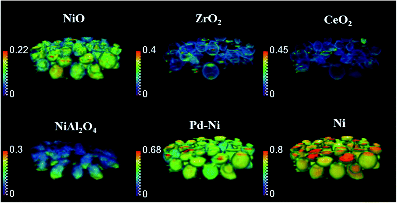
The phase distribution volume results of the 3D-XRD-CT scan performed at room temperature are presented in Fig. 1. Full profile Rietveld analysis of the reconstructed diffraction patterns revealed that the initial catalyst comprised NiO, ZrO2, CeO2 and PdO distributed on a θ-Al2O3 support (Fig. S2 in the ESI†). NiO was found in all catalyst particles, with a rather uniform distribution and a few particles were seen to be particularly rich in this phase, predominantly near the core. The distribution of ZrO2 was mainly observed to be located on the edges of the catalyst particles. The ZrO2 was not present in every catalyst particle; it was possible to identify particles without any ZrO2 as well as a few particles rich in this phase. As reported in our previous study,19 the ZrO2 phase possessed an egg-shell distribution. Regarding the CeO2 phase, its distribution varied for each particle. Indeed we observed the whole range of particle distributions, ranging from cores rich in CeO2, uniform distributions, to some particles containing CeO2 only at the edges, similar to the distribution of ZrO2.71 The distribution of PdO was challenging to extract due to its low loading (0.2 wt%) and also due to peak overlap with ZrO2 (Fig. S4 in the ESI†). | ||
| Fig. 1 Volume rendering of the normalised scale factors data volume (normalised over the maximum value of the scale factor in the entire process) for NiO, Zr O 2 and Ce O 2 phases, obtained from the Rietveld analysis of the 3D-XRD-CT data collected at room temperature. | ||
The spatial distribution of ZrO2 and CeO2 in one of the XRD-CT cross sections (cross section from the middle of 3D volume presented in Fig. 1) collected at room temperature as well as the distribution of their lattice parameter a and crystallite size are presented in Fig. 2 (cross-section taken from the middle of catalyst bed volume). Regarding the distribution of the ZrO2 phase, regions with hot spots (high intensity) of this material are characterised by a larger crystallite size (∼20 nm) and a lower lattice parameter a, meaning that the phase comprised relatively pure ZrO2. In addition, as previously shown, two regions of mixed ZrO2–CeO2 phases could be identified, one with a lattice parameter a ∼ 3.61 Å and crystallite size of ∼12 nm and second region with a greater lattice parameter a being around 3.63 Å and 8 nm crystallite size.19 As the size of the ionic radius of Ce4+ is ∼20% greater than the ionic radius of Zr4+ (0.97 Å and 0.78 Å respectively72), we propose that substitution of Ce4+ into the structure of ZrO2 occurs and leads to an increased lattice parameter.73
 | ||
| Fig. 2 Spatial distribution of normalised scale factor (in respect to maximum value in this XRD-CT image), spatial distribution of crystallite size and lattice parameter a for CeO2 and ZrO2 collected at room temperature (fresh catalyst). | ||
Finally, the distribution of a fourth phase, consisting of a relatively pure CeO2, was found to be present in the core of the particles, with a uniform distribution of lattice parameter ∼5.38 Å and crystallite size of ∼10 nm. Summarising the results of CeO2–ZrO2 distribution, the reported four species are in a good agreement with our previous study on this catalyst.19
These CeO2 and ZrO2 components, although having different symmetry (cubic-fluorite type with space group Fm![[3 with combining macron]](https://www.rsc.org/images/entities/char_0033_0304.gif) m and tetragonal lattice with P42/nmc space group respectively), are known to form solid solutions with multiple configurations. The analysis of such structures which aims to determine the structure–composition relationships is anything but trivial. As reported by Yashima et al.74–76 these mixed phases can be categorised into three different tetragonal phases, according to the ratio between the lattice parameters a/c. In addition, the mixed solution with quantities of CeO2 above 80 wt% crystallises in a cubic structure (fluorite type).73,77 Although multiple solid solutions with different crystal structures are possible, it has been proposed that CeO2–ZrO2 (and the solid solutions) comprise a crucial component for yielding an optimal POX catalyst due to its thermal stability and its ability to supress coke formation through its enhanced redox properties and improved oxygen storage capacity.78,79 As reported in the work of Ismagilov et al.,80 increasing the content of Zr in the mixed CeO2–ZrO2 oxide improves the catalytic performance of the resulting catalyst in terms of CH4 conversion as well as CO and H2 yield. However, there is an optimal composition with Ce and Zr ratio being 1:1 after which no further improvement is observed, possibly even a slight decrease in CO and H2 yield.
m and tetragonal lattice with P42/nmc space group respectively), are known to form solid solutions with multiple configurations. The analysis of such structures which aims to determine the structure–composition relationships is anything but trivial. As reported by Yashima et al.74–76 these mixed phases can be categorised into three different tetragonal phases, according to the ratio between the lattice parameters a/c. In addition, the mixed solution with quantities of CeO2 above 80 wt% crystallises in a cubic structure (fluorite type).73,77 Although multiple solid solutions with different crystal structures are possible, it has been proposed that CeO2–ZrO2 (and the solid solutions) comprise a crucial component for yielding an optimal POX catalyst due to its thermal stability and its ability to supress coke formation through its enhanced redox properties and improved oxygen storage capacity.78,79 As reported in the work of Ismagilov et al.,80 increasing the content of Zr in the mixed CeO2–ZrO2 oxide improves the catalytic performance of the resulting catalyst in terms of CH4 conversion as well as CO and H2 yield. However, there is an optimal composition with Ce and Zr ratio being 1:1 after which no further improvement is observed, possibly even a slight decrease in CO and H2 yield.
3.2 Temperature ramping
A series of XRD maps were collected during the temperature ramp from room temperature to 800 °C under He flow. In order to follow the solid-state changes occurring in the catalyst as a function of temperature, all diffraction patterns from each line scan were summed (150 diffraction patterns collected in one line scan); these diffraction patterns are presented in Fig. 3. Only after heating to 780 °C does a new peak (position 2θ = 3.45°) appear in the diffraction patterns. This peak was associated to a new phase, identified as a cubic Pd–Ni alloy and it was found to be formed in the entire catalyst bed (i.e. axially). The formation of this alloy is a consequence of PdO reducing to metallic Pd (thermal reduction under He flow at high temperatures).81 The refined position of the principal reflection (111 reflection with d = 2.25 Å), shown in Fig. 3, indicated that the major element present in the metallic alloy was Pd.82 | ||
| Fig. 3 (Top) summed diffraction patterns collected with diffraction mapping (150 diffraction patterns summed for one line scan) during the temperature ramp in He. The chosen region of interest shows the two last maps (from 680 °C to 800 °C with the step of around 5 °C between the line scans). The red lines indicate the beginning of each map and the data are presented from the inlet of reactor towards the outlet of reactor. Bottom: simulated diffraction patterns for NiO, NiAl2O4, Al2O3 and Pd–Ni. | ||
In addition, the phase identification of the diffraction data collected at temperatures above 780 °C revealed the formation of NiAl2O4. Although the structures of Al2O3, NiO and NiAl2O4 possess overlapping reflections (Fig. 3, bottom panel), when using the Rietveld analysis it was possible to identify the presence of the NiAl2O4 phase and the corresponding disappearance of NiO36 (see Fig. S5 in the ESI†).
After reaching 800 °C, three XRD-CT datasets were collected at different positions in catalyst bed: reactor inlet, middle of reactor and reactor outlet (Fig. 4). During the temperature ramp NiO was seen to react with the Al2O3 support, forming the new phase NiAl2O4. As the solid-state reaction between NiO and Al2O3 proceeded during the XRD-CT data collection at 800 °C, the apparent gradient between NiO/NiAl2O4 in Fig. 4 is due to a time effect (XRD-CT data at the reactor inlet collected first) rather than a thermal gradient in the catalyst reactor (see Fig. S6 in the ESI†).
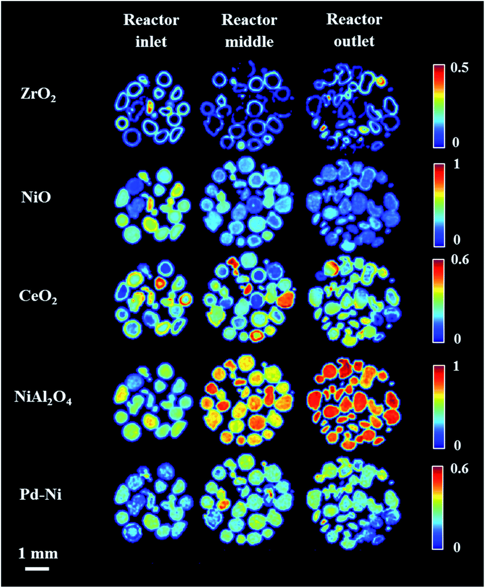 | ||
| Fig. 4 Phase distribution maps created from the Rietveld analysis of XRD-CT data collected (normalised scale factors) collected at three different positions: reactor inlet, middle of reactor and outlet of reactor under atmosphere of He at 800 °C (according to the order of data collection). | ||
The newly formed phase, Pd–Ni alloy was uniformly distributed in the catalyst bed (i.e. as a function of bed height). Also, its composition (i.e. amount of Ni and Pd in the Pd–Ni alloy) in the catalyst bed remained uniform (as verified by the diffraction patterns collected at 800 °C under He presented in Fig. S7 in the ESI†). It is important to note that with the resolution of the reconstructed XRD-CT images in this work (i.e. voxel size 40 × 40 × 80 μm 3) the distribution of the Pd-containing species can only be treated as an estimate of the real distribution. As shown with the SEM/EDX measurements (Fig. S8–S9 in the ESI†) and in our previous work on this catalytic material (with a voxel size of 1 × 1 × 1 μm3),19 the exact distribution of Pd-containing species is in the form of discrete regions around the particles edge.
3.3 In situ reduction
For the reduction/activation step, the catalyst was reduced in an H2 environment (20% H2/He) for 2 h. During the first 10 min of reduction two XRD maps were collected to investigate the temporal changes during gas introduction (Fig. 5 and 6). 3D-XRD-CT data were collected in between the XRD maps (Fig. 7).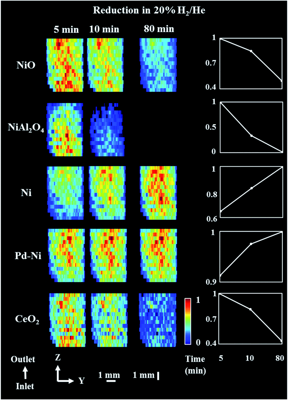 | ||
| Fig. 5 Phase distribution maps of NiO, NiAl2O4, Ni, Pd–Ni and CeO2 corresponding to the normalized scale factors obtained through Rietveld analysis of the XRD maps collected during reduction step. (Right) relative changes of each phase during the reduction step. XRD maps are presented from the inlet of reactor towards the outlet of reactor. The NiO phase is already present in traces when compared to initial composition at room temperature. Corresponding diffraction patterns can be found in the ESI (Fig. S12†). | ||
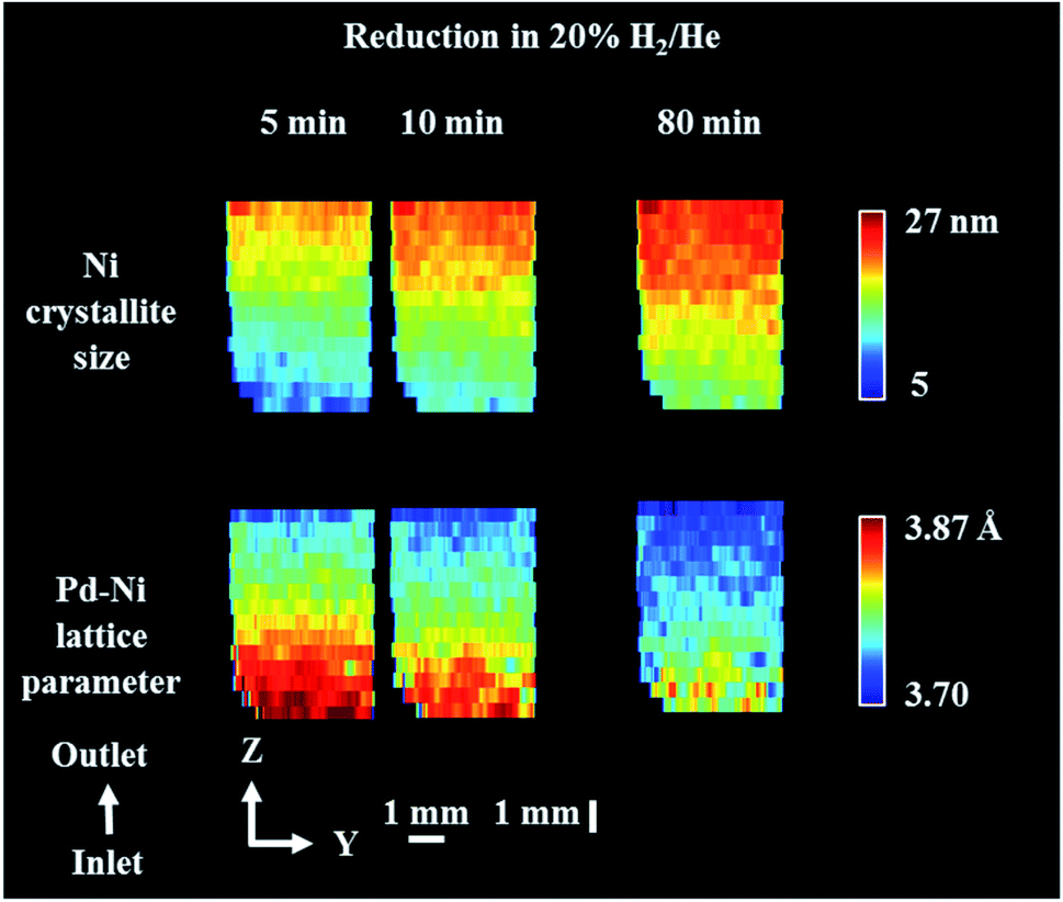 | ||
| Fig. 6 Phase distribution maps of Ni crystallite size and Pd–Ni lattice parameter obtained through Rietveld analysis of the XRD maps collected during reduction step. XRD maps are presented from the inlet of reactor towards the outlet of reactor. Corresponding diffraction patterns can be found in the ESI (Fig. S14†). | ||
 | ||
| Fig. 7 Volume rendering of the normalised scale factors data volume (normalised over the maximum value of scale factor in the entire process) obtained from the Rietveld analysis of the 3D-XRD-CT data collected during the reduction process at 800 °C under 20% of H2/He. | ||
During the reduction, both NiO and NiAl2O4 were observed to reduce to metallic Ni. As reported in our previous study,19 the reduction of NiO and NiAl2O4 to metallic Ni did not depend on the position in the catalyst bed and it was only related to the time-on-stream. As the XRD map was collected starting from the bottom to the top of reactor (reactor inlet to reactor outlet direction), it is clear than the difference in composition was related to time of measurement (Fig. 5). Regarding the CeO2, its quantity decreased in the entire catalyst bed and this can possibly be explained by the formation of a CeAlO3 structure. As previously reported,40,48,49,83 at high temperatures and under reducing conditions Ce4+ was found to readily reduce to Ce3+ and form crystalline CeAlO3 (110 reflection at d = 2.66). In our study it was not possible to identify this phase unambiguously, as there were no new peaks formed during reduction. However, taking into consideration that concomitant CeO2 disappeared from core of catalyst particles (Fig. S10 in the ESI†) and a slight decrease in Al2O3 intensity was also observed (based on the scale factors, Fig. S11 in the ESI†) this could be attributed to the formation of poorly crystalline/amorphous CeAlO3. The possible role of CeAlO3 phase has been discussed and there are disagreements as to its significance in the literature. In some reports the CeAlO3 phase has been suggested to be inactive,49 whereas in others CeAlO3 was thought to provide an improvement in catalyst stability and suppression of coke formation.40,84 Finally, no changes were observed in the ZrO2 distribution map during the reduction step (Fig. S11 in the ESI†).
Fig. 6 presents the distribution of Pd–Ni lattice parameter and the distribution of Ni crystallite size. The crystallite size of metallic Ni in the catalyst bed showed a gradient from the reactor inlet to the reactor outlet; the crystallite size of Ni is higher for catalyst particles closer to reactor outlet (27 nm and 10 nm for outlet and inlet of reactor respectively) and during the reduction process the crystallite size of metallic Ni gradually increased. At the same time, we observed that the lattice parameter of the Pd–Ni changed as a function of bed height (see Fig. S13 in the ESI†). The bottom of the reactor (reactor inlet) has a higher lattice parameter, meaning that the Pd–Ni contained more Pd in its structure, as the size of Pd atomic radius is ∼10% larger than Ni (atomic radius of Pd 137 pm and atomic radius of Ni 125 pm.82 The top of the reactor (reactor outlet) contained less Pd, however the mixed metallic alloy appeared to be retained. During the reduction step the lattice parameter of this mixed phase decreased, meaning that more Ni was incorporated in its structure as the reduction of Ni containing species (mainly NiAl2O4) proceed. Regarding the crystallite size of metallic Ni, the observed gradient in the length of catalyst reactor may be a result of temperature gradients induced with the sample movement during the mapping measurements (i.e. in order to probe the top of reactor the sample stage needs to move down and thus the bottom of the reactor is exposed to lower temperatures during the mapping measurements); at the end of the reduction process the crystallite size of Ni species became more uniform with the crystallise size range between 16–25 nm.
The distribution of the various catalyst components during the reduction is shown in Fig. 7 (3D-XDR-CT data collected after first two XRD maps and before the third XRD map). The distribution of all Ni-containing phases was seen to be uniform. As concluded from the XRD maps in Fig. 5, the quantity of CeO2 decreased during the reduction and the new distribution of CeO2 was mainly found on the edges of catalyst particles, being now very similar to ZrO2. Also, the distribution of NiAl2O4 during the reduction step was not uniform; during the data collection the NiAl2O4 phase was found to be more reduced (i.e. more of NiAl2O4 disappeared) in the upper parts of the catalyst bed (closer to reactor outlet) due to the time effect of measurement; the 3D-XRD-CT data were also collected in the order from reactor inlet to reactor outlet.
3.4 Partial oxidation of methane
Upon completion of the reduction/activation process, the POX reaction mixture was introduced into the reactor. Three different reaction conditions were tested: first a reaction mixture with CH4:O2 2:1 (POX1), then a reaction mixture with CH4:O2 4:1 (POX2) and at the end again a reaction mixture with CH4:O2 2:1 (POX3). The chosen experimental protocol aimed to investigate the solid-sate chemistry under optimal conditions for syngas synthesis (CH4:O2 2:1) as well as under conditions with higher CH4:O2 ratio (4:1) where significant coking is expected to occur. The introduction of the final reaction mixture with optimal CH4:O2 ratio intended to evaluate the impact of the changes in the catalyst structure and its performance, induced with the coke deposition.
During each reaction mixture, two XRD maps were collected (during the first 10 minutes after the introduction of reactive gases) in order to study the relatively fast solid-state changes taking place after introducing the reaction mixture to the reactor. Then, 10 cross sections were collected during reaction (what we recently termed a 5D-XRD-CT imaging experiment) and finally, after 80 min reaction a final XRD map was collected (two XRD map for the reaction mixture POX2). In the case of the last reaction mixture (POX3), only five XRD-CT datasets were collected due to experimental time limitations.
Fig. 8 shows the distribution maps of CeO2, Pd–Ni and graphite, based on normalised scale factors, as well as the distribution of lattice parameter and crystallite size of metallic Ni. The changes of note include the disappearance of the Pd–Ni phase, which is quite noticeable at the end of POX1 reaction and occurs predominantly at the reactor inlet (Fig. S17 in the ESI†). The Pd–Ni peak was seen to continuously shift towards higher scattering angles during the reaction, at the same time becoming broader and of lower intensity. This phenomenon could be explained through the temperature-driven incorporation of Ni in the Pd–Ni structure resulting in the formation of a large spread of solid solutions with different Ni/Pd ratios85,86 (Fig. S13 in the ESI†). For this reason, at the end of POX1 reaction the main reflection of the Pd–Ni phase significantly decreased.
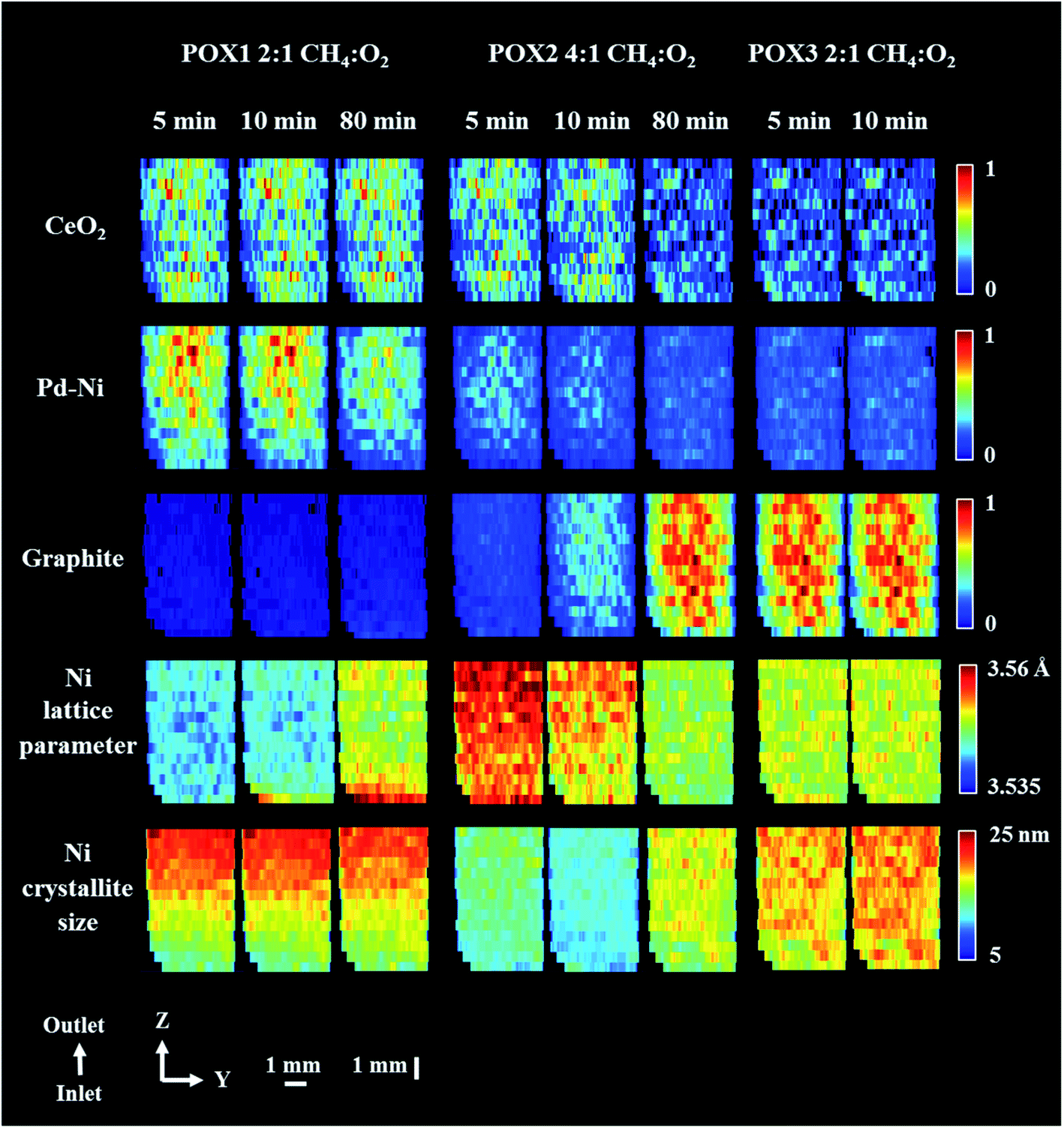 | ||
| Fig. 8 Phase distribution maps of normalised scale factors for CeO2, Pd–Ni and graphite, Ni lattice parameter and Ni crystallite size obtained through Rietveld analysis of the XRD maps collected during POX reaction. XRD maps are presented from the inlet of reactor towards the outlet of reactor. Corresponding diffraction patterns can be found in the ESI (Fig. S17 and S22 in the ESI.†). The XRD map collected at the end of POX2 reaction conditions (after 120 minutes) is presented in Fig. S23 in the ESI.† | ||
In contrast reflections for the metallic Ni phase (111 and 200) showed remarkably little change in height, a gradual shift towards lower scattering angle and only after 80 min reflection broadening (Fig. S18 in the ESI†); we propose that this phenomenon is due to intercalation of carbon into the Ni crystal structure. Although the formation of Ni–C occurs along the entire catalyst bed, it is more pronounced at the reactor inlet where the first deposits of graphitic carbon were also identified. In this study, we modelled this phenomenon by refining the Ni crystallite size and lattice parameter values. We note that the changes seen in the behaviour of the metallic Ni species maps remarkably well onto the catalytic behaviour (CO/H2 production) from both the operando study and a separate laboratory experiment (see Fig. S19†). More specifically, the catalyst reached its best performance during the POX1 reaction mixture after 2 h of time on stream which could suggest that the interstitial solution of Ni–C is part of catalyst active species. It should be noted that we did not observe any reoxidation of Ni species for the duration of the POX experiment.
After introducing a methane rich gas stream (reaction mixture POX2), significant formation of graphitic carbon could be observed in the first five minutes of reaction, this time occurring uniformly along the entire length of the catalyst bed. As expected, the deposition of coke was coincident with a decrease in crystallite size of Ni (observed as peak broadening) and an increase in its lattice parameter (observed as peak shift towards lower scattering angles),87 suggesting that the prerequisite for graphite formation is the intercalation of carbon into the Ni lattice. Although, the presence of Ni–C was found to be crucial for the catalyst activity, its progressing carbonatation during the POX2 reaction mixture led eventually to a catalyst with lower activity. The accumulation of carbon species over Ni catalyst can effectively block the access to active components, through the formation of coke, filamentous carbon and/or metallic carbides.88–91
The coke formation can possibly be explained with two different mechanisms: (1) methane dehydrogenation occurring for the high partial pressure of methane, observed in this study mainly at the reactor inlet at the end of POX1 reaction mixture and (2) CO disproportionation to carbon and CO2, observed in this study in the higher parts of reactor (towards reactor outlet) as the CO is expected to form through the reaction between CH4 and CO2 (formed through the initial combustion of CH4 at the reactor inlet).29,30,33 Under the employed reaction conditions in the present study (C/O ≥ 2) the formation of carbon is predicted and in good agreement with the C–H–O diagram determined from the thermodynamic calculations.92 It is important to note that when the Ni–Pd/CeO2–ZrO2/Al2O3 catalyst operates in the carbon-free region (C/O < 2), it shows high stability and no apparent formation of coke deposits.93,94
The coke formation was seen to slow down at the end of reaction mixture POX2 while its quantity remained high for the duration of the POX3 reaction mixture measurements. The diffraction data show the presence of crystalline graphite till the end of the experiment (Fig. S20†) and complementary laboratory TGA measurements (see Fig. S21†) performed on the recovered catalyst sample did not reveal the presence of any other forms of coke.
The phase distribution volumes of all components present during the studied POX conditions (i.e. POX1, POX2 and POX3 reaction mixtures) are shown in Fig. 9 (the overall changes in normalised mean scale factors during the entire experiment are shown in Fig. S24†). During the POX reaction, the distribution of the mixed CeO2–ZrO2 solution remained unchanged. More importantly, the formation of graphite was found to develop on the particles rich in metallic Ni and supported on Al2O3, thus suggesting that the carbon was being built up in the catalyst particles, significantly changing their shape (i.e. particles cracking) and density (i.e. particle expansion) (Fig. S25–S26 in the ESI†). Therefore, the apparent overall decrease in scattering signal intensity of all other catalyst components during the POX2 and POX3 reaction mixture is associated with a decrease in the density of the catalyst particles.
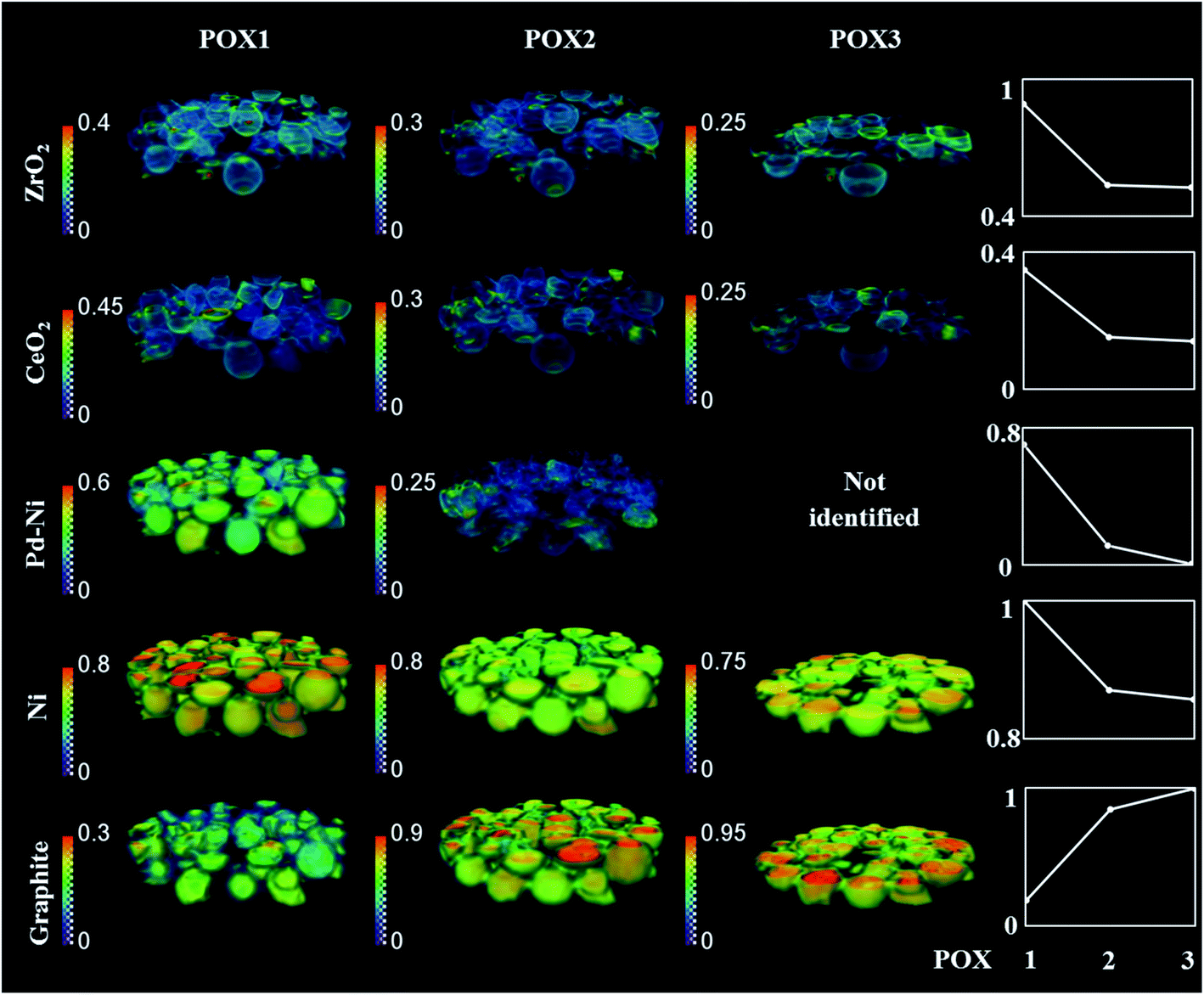 | ||
| Fig. 9 Volume rendering of the normalised scale factors data volume (normalised over the maximum value scale factor reading in the entire process) obtained from the Rietveld analysis of the 3D-XRD-CT data collected during the reaction mixture POX1, POX2 and POX3. Plots on the right corresponds to normalise mean scale factors 3D volume during the POX reaction conditions (for normalised mean scale factors during the entire experiment see Fig. S24†). The normalisation was done with respect to maximum value for the entire experiment. Note that only five XRD-CT slices were collected for POX3 reaction mixture. | ||
To gain further insight into the evolution of graphite and Ni crystallite size, a binary mask was created for each dataset based on the ZrO2 distribution maps presented in Fig. 10A and applied to the graphite and Ni crystallite size maps. The average values for each dataset were calculated and the results are plotted in Fig. 10B. It can be clearly seen that the graphite forms and grows predominantly at the regions of the catalyst particles where CeO2–ZrO2 is absent. However, it can also be seen that although CeO2–ZrO2 can provide enhanced resistance to graphite it cannot prevent its growth (Fig. S25–S26†).
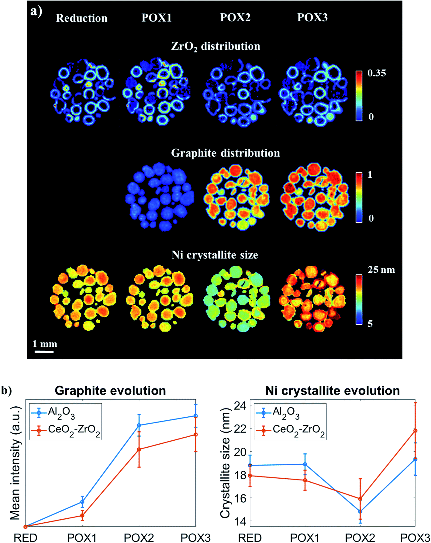 | ||
| Fig. 10 (Panel a) Spatial distribution of ZrO2, graphite and metallic Ni crystallite size obtained through Rietveld analysis performed on XRD-CT data collected for various conditions: reduction, POX1, POX2 and POX3 from the middle of catalyst bed (middle of 3D-XRD-CT data volume). The observed reduction of Ni crystallite size is in fact a result of carbon intercalation. (Panel b) Evolution of graphite concentration and Ni crystallite size at the catalyst particles where CeO2–ZrO2 (shell) and Al2O3 (core) are primarily present. | ||
The distribution of the Ni crystallite size during the reduction process and during the reaction mixture POX1 were comparable (Fig. 10). Generally, the core of the catalyst particles was seen to contain larger Ni crystallites when compared to the edges which is also evident from Fig. 10B. This provides evidence of a direct correlation between the presence of the CeO2–ZrO2 promoter and the dispersion of Ni crystallites.48,95 As the reaction mixture POX2 was introduced to the reactor, the Ni crystallite size generally decreased in the catalyst particles (with simultaneous increase in lattice parameter), which suggests the intercalation of carbon into the Ni structure. It can also be seen that the slope between POX1 and POX2 is more negative for the areas in the catalyst particles where CeO2–ZrO2 is absent. This is consistent with the graphite results as it implies that the incorporation of the interstitial carbon in the Ni structure is taking place at a higher extent in the Ni supported on Al2O3. However, a reversed egg-shell distribution for the Ni crystallite size is observed when comparing the results obtained from POX1 and POX3 reaction conditions. This implies that the metal–support interaction between Ni and CeO2–ZrO2 is not sufficiently strong and indeed weaker compared to the Ni–Al2O3 interaction and as a result the Ni crystallites gradually sinter under POX reaction conditions. The strong interaction between the metallic species and the support material was shown to be crucial in preventing the Ni species from sintering as well as improving the resistance to coke formation and growth, since larger crystallites are more prone to carbon deposits.18,96,97
These results are further supported by the histograms presented in Fig. 11; these histograms are derived from the images that yielded the average values shown in Fig. 10. Specifically, it can be seen that the shape of the Ni crystallite size distribution is similar for both the Al2O3 and the CeO2–ZrO2 areas but there is a right hand asymmetry towards larger values for the former. Importantly, in POX2, the Ni crystallite size distribution corresponding to the Al2O3 areas is becoming wider and is shifted significantly towards lower values which, as previously discussed, is attributed to the interstitial carbon formation. Under POX3, this distribution is becoming narrower and shifted to higher values implying the partial disappearance of this species. On the other hand, it is evident that the Ni crystallites are beginning to sinter significantly in the CeO2–ZrO2 areas; the wider and shifted distribution towards larger values implies a weaker metal–support interaction.
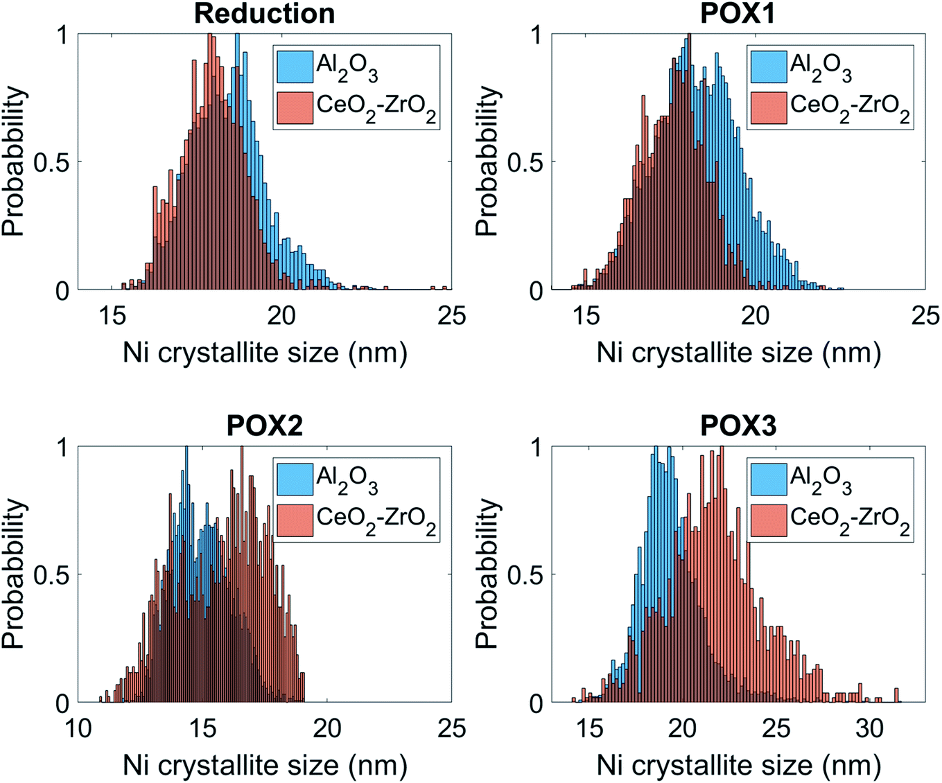 | ||
| Fig. 11 Histograms describing the distribution of graphite intensity under POX1, POX2 and POX3 reaction conditions for the Al2O3 and CeO2–ZrO2 areas. | ||
The growth of graphitic coke had a detrimental effect on physical structure of catalyst particles as it led to their expansion, formation of cracks in their structure and even their breakage (Fig. S27–S28†). In addition, the formation of coke significantly decreased the catalyst performance verified by operando mass spectrometry and laboratory quantitative measurements (Fig. S19†). The catalyst showed an excellent performance with stoichiometric POX1 reaction mixture (2:1), reaching a H2 yield above 90% and CH4 conversion of 84%. Switching to POX2 reaction mixture resulted in a decrease of both H2 yield and CH4 conversion, as during these conditions there was not enough O2 to convert the rich in CH4 inlet stream resulting in significant catalyst coking. After introduction of POX3 reaction mixture, the H2 yield was lower when compared to POX1 reaction mixture (70% according to quantitative analysis) and the decrease in catalyst performance was due to the multiple physico-chemical solid-state chemistry changes and mechanical changes occurring during the POX2 reaction mixture (i.e. coke deposition and Ni crystallites sintering on the catalyst surface).
4. Summary and conclusions
In this work we presented the results from an operando 5D chemical imaging experiment during the reduction/activation and POX reaction employing a Ni–Pd/CeO2–ZrO2/Al2O3 catalyst. Specifically, we investigated in 3D the real-time evolution of the solid-state chemistry of this complex catalytic system under POX operating conditions. We aimed to gain a better understanding of the role of each catalyst component by looking at the changes in their physico-chemical properties upon placing the catalyst under both stoichiometric and CH4-rich reaction conditions. This multi-length scale chemical imaging experiment performed with a combination of 3D XRD-CT and XRD mapping allowed us to track the evolving solid-state chemistry taking place in the catalyst both at the particle and at the reactor level, investigating the changes in the range of μm to nm. We were able to observe significant chemical gradients present both at the single catalyst particle level (i.e. intraparticle radial gradients) and along the reactor (i.e. reactor axial gradients). More specifically we showed:(1) At operating temperatures (i.e. 800 °C), the Pd-containing species are present in the form of a solid solution of Pd–Ni metallic alloys. The formation of such alloys under the flow of He clearly illustrates the promoting role of Pd, as the reduction of the Ni species occurred in an inert gas atmosphere. During the reduction stage, the quantity of metallic Ni incorporated in the Pd–Ni alloy was increased due to the reduction of the Ni-containing species (i.e. mainly NiAl2O4). The further incorporation of Ni into the Pd–Ni resulted in the spread of the alloy mass population, leading to gradual decrease in the intensity of Pd–Ni diffraction peak, until it was no longer possible to observe it. The resolution of the reconstructed XRD-CT images (voxel size of 40 μm × 40 μm × 40 μm) was not high enough to allow us to extract any further information regarding the Pd–Ni metallic alloy during this experiment. However, our results suggest that the metallic Pd–Ni alloy is not stable under reaction conditions and one can argue that the significant alloying of Pd with Ni may hinder the promoting role of Pd in this catalyst.
(2) During the POX reaction, the growth of crystalline graphite was observed with XRD mapping; first deposits were identified at the reactor inlet after 80 minutes under the initial reaction mixture with CH4:O2 ratio of 2:1. This was coincident with the broadening and shift of Ni diffraction peaks towards lower scattering angles, which suggested that the presence of graphite was preceded by the formation of an interstitial solid solution of Ni–C, considered as the intermediate species formed in the methane activation step. In fact, the presence of such species in the structure of catalyst at its highest performance can only suggest that Ni–C is part of the catalyst active species. After switching to reaction mixture with CH4:O2 ratio of 4:1 (reducing conditions) the formation graphite was observed instantaneously, while the activity of catalyst was gradually decreasing with time on stream. The accumulation of carbon species due to their insufficient removal (both through gas and bulk oxygen reaction) suggests that the catalyst active species are susceptible to changes in the gas phase composition. It is important to note that both the analysis of the diffraction data and post-reaction thermogravimetric measurements do not suggest the presence of any other major carbonic species, such as amorphous carbon.
(3) The coke deposition during the POX reaction, especially when the CH4 rich stream was applied, occurred predominantly in regions where the mixed binary solution of CeO2–ZrO2 was absent. With the diffraction imaging technique, we showed that across one catalyst particle it is possible to differentiate between two regions: (1) core of catalyst particles where the Ni is supported over Al2O3 and (2) shell of catalyst particles, where the Ni is supported on CeO2–ZrO2/Al2O3. The first region is characterised with the metallic Ni strongly interacting with Al2O3 support, which provides a good resistance towards the Ni particles sintering. However, the Al2O3 support, with both Lewis and Brønsted acidity, promotes coke deposition in the POX reaction. The second region, which contains the CeO2–ZrO2 support, although it exhibits enhanced resistance to coke formation due to the oxygen storage properties of CeO2–ZrO2, it does not prevent the Ni crystallites from sintering under reaction conditions, which is most likely caused by a weaker metal–support interaction. The characterisation of catalysts with such design, where the support materials exhibit different properties (inactive and acidic Al2O3vs. redox CeO2–ZrO2), should be performed with spatially-resolved techniques as the conventional bulk measurements provide only average information and do not take into account the intraparticle heterogeneities.
(4) During the catalyst activation/reduction step, the CeO2 species were stabilised only in the regions where the ZrO2 was present (i.e. catalyst particle shell) in the form of a binary CeO2–ZrO2 solution. The CeO2 species present initially in the particle core were seen to disappear during the reduction, most likely interacting with the Al2O3 support and forming the CeAlO3 phase. Although it has been proposed that the CeAlO3 phase may be effective in carbon removal, through the chemical cycle of Ce3+/Ce4+40,98 our results suggest that only the interaction of CeO2 with ZrO2 yields a support that can successfully prevent coke deposition whereas the interaction between CeO2 and Al2O3 decreases the redox properties of the CeO2 oxygen storage material. This observation also showed that more attention should be paid to the preparation method, aiming towards improved distribution of the ZrO2 in the catalyst core, which would help to stabilise the CeO2 and mitigate the coke deposition on the metallic Ni.
With the 5D diffraction imaging technique we were able to investigate an inhomogeneous by design Ni/Al2O3 based catalyst. The analysis of the spatially-resolved diffraction patterns provided new insight into the structural changes induced by the operating conditions, not possible to obtain with conventional bulk measurements. The current composition yields a catalyst with high initial performance and we believe that its stability can be further improved by dispersing more uniformly the Pd-containing species and enhancing the interplay between the two distinctive particle regions (i.e. core and shell regions).
Author contributions
Experimental plan, D. M., A. V., S. D. M. J. and A. M. B.; material preparation, I. Z. I., E.V. M., V.V. K., synchrotron measurements, D. M., A. V. and S.D.M. J., beamline support, M.M., data analysis, D. M. and A. V.; SEM/EDX measurements, V. M.; original draft preparation, D. M. and A. V.; writing—review and editing, all authors.; supervision, S. D. M. J., R. J. C. and A. M. B.; funding acquisition, S. D. M. J. and A. M. B.Data availability
All data are available from the corresponding authors on reasonable request.Conflicts of interest
There are no conflicts to declare.Acknowledgements
Dorota Matras and Antonis Vamvakeros were supported through funding received from the European Union Horizon 2020 research and innovation programme under grant agreement no. 679933 (MEMERE project). Andrew M. Beale acknowledges EPSRC (grants EP/R026815/1 and EP/S016481/1). We acknowledge the European Synchrotron Radiation Facility for beamtime.References
- R. Horn and R. Schlögl, Methane Activation by Heterogeneous Catalysis, Catal. Lett., 2015, 145, 23–39 CrossRef CAS.
- A. I. Olivos-Suarez, À. Szécsényi, E. J. M. Hensen, J. Ruiz-Martinez, E. A. Pidko and J. Gascon, Strategies for the Direct Catalytic Valorization of Methane Using Heterogeneous Catalysis: Challenges and Opportunities, ACS Catal., 2016, 6, 2965–2981 CrossRef CAS.
- J. S. Lee and S. T. Oyama, Oxidative Coupling of Methane to Higher Hydrocarbons, Catal. Rev., 1988, 30(2), 249–280 CrossRef CAS.
- G. J. Hutchings, M. S. Scurrell and J. R. Woodhouse, Oxidative Coupling of Methane Using Oxide Catalysts, Chem. Soc. Rev., 1989, 18(0), 251–283 RSC.
- K. Otsuka, K. Jinno and A. Morikawa, Active and Selective Catalysts for the Synthesis of C2H4 and C2H6via Oxidative Coupling of Methane, J. Catal., 1986, 100(2), 353–359 CrossRef CAS.
- A. Galadima and O. Muraza, Revisiting the Oxidative Coupling of Methane to Ethylene in the Golden Period of Shale Gas: A Review, J. Ind. Eng. Chem., 2016, 37, 1–13 CrossRef CAS.
- T. V. Choudhary, E. Aksoylu and D. Wayne Goodman, Nonoxidative Activation of Methane, Catal. Rev., 2003, 45(1), 151–203 CrossRef CAS.
- X. Guo, G. Fang, G. Li, H. Ma, H. Fan, L. Yu, C. Ma, X. Wu, D. Deng and M. Wei, et al., Direct, Nonoxidative Conversion of Methane to Ethylene, Aromatics, and Hydrogen, Science, 2014, 344(6184), 616–619 CrossRef CAS PubMed.
- C. Karakaya and R. J. Kee, Progress in the Direct Catalytic Conversion of Methane to Fuels and Chemicals, Prog. Energy Combust. Sci., 2016, 55, 60–97 CrossRef.
- H. Jahangiri, J. Bennett, P. Mahjoubi, K. Wilson and S. Gu, A Review of Advanced Catalyst Development for Fischer–Tropsch Synthesis of Hydrocarbons from Biomass Derived Syn-Gas, Catal. Sci. Technol., 2014, 4(8), 2210–2229 RSC.
- M. E. Dry, High Quality Diesel via the Fischer–Tropsch Process – a Review, J. Chem. Technol. Biotechnol., 2002, 77(1), 43–50 CrossRef CAS.
- Y.-S. Oh, H.-S. Roh, K.-W. Jun and Y.-S. Baek, A Highly Active Catalyst, Ni/Ce–ZrO2/θ-Al2O3, for on-Site H2 Generation by Steam Methane Reforming: Pretreatment Effect, Int. J. Hydrogen Energy, 2003, 28, 1387–1392 CrossRef CAS.
- A. J. de Abreu, A. F. Lucrédio and E. M. Assaf, Ni Catalyst on Mixed Support of CeO2–ZrO2 and Al2O3: Effect of Composition of CeO2–ZrO2 Solid Solution on the Methane Steam Reforming Reaction, Fuel Process. Technol., 2012, 102, 140–145 CrossRef CAS.
- T. de Freitas Silva, J. A. C. Dias, C. G. Maciel and J. M. Assaf, Ni/Al2O3 Catalysts: Effects of the Promoters Ce, La and Zr on the Methane Steam and Oxidative Reforming Reactions, Catal. Sci. Technol., 2013, 3, 635–643 RSC.
- H. Li, H. Xu and J. Wang, Methane Reforming with CO2 to Syngas over CeO2-Promoted Ni/Al2O3–ZrO2 Catalysts Prepared via a Direct Sol–Gel Process, J. Nat. Gas Chem., 2011, 20, 1–8 CrossRef CAS.
- R. Benrabaa, A. Barama, H. Boukhlouf, J. Guerrero-Caballero, A. Rubbens, E. Bordes-Richard, A. Löfberg and R.-N. Vannier, Physico-Chemical Properties and Syngas Production via Dry Reforming of Methane over NiAl2O4 Catalyst, Int. J. Hydrogen Energy, 2017, 42, 12989–12996 CrossRef CAS.
- S. Corthals, J. Van Nederkassel, J. Geboers, H. De Winne, J. Van Noyen, B. Moens, B. Sels and P. Jacobs, Influence of Composition of MgAl2O4 supported NiCeO2ZrO2 catalysts on Coke Formation and Catalyst Stability for Dry Reforming of Methane, Catal. Today, 2008, 138, 28–32 CrossRef CAS.
- T. V. Choudhary and V. R. Choudhary, Energy-Efficient Syngas Production through Catalytic Oxy-Methane Reforming Reactions, Angew. Chem., Int. Ed., 2008, 47(10), 1828–1847 CrossRef CAS PubMed.
- A. Vamvakeros, S. D. M. Jacques, M. Di Michiel, D. Matras, V. Middelkoop, I. Z. Ismagilov, E. V. Matus, V. V. Kuznetsov, J. Drnec and P. Senecal, et al., 5D Operando Tomographic Diffraction Imaging of a Catalyst Bed, Nat. Commun., 2018, 9, 4751 CrossRef CAS PubMed.
- R. Horn, K. A. Williams, N. J. Degenstein, A. Bitsch-Larsen, D. Dalle Nogare, S. A. Tupy and L. D. Schmidt, Methane Catalytic Partial Oxidation on Autothermal Rh and Pt Foam Catalysts: Oxidation and Reforming Zones, Transport Effects, and Approach to Thermodynamic Equilibrium, J. Catal., 2007, 249, 380–393 CrossRef CAS.
- G. P. Berrocal, A. L. M. Da Silva, J. M. Assaf, A. Albornoz and M. d. C. Rangel, Novel Supports for Nickel-Based Catalysts for the Partial Oxidation of Methane, Catal. Today, 2010, 149, 240–247 CrossRef CAS.
- M. A. Kerzhentsev, E. V. Matus, I. A. Rundau, V. V. Kuznetsov, I. Z. Ismagilov, V. A. Ushakov, S. A. Yashnik and Z. R. Ismagilov, Development of a Ni–Pd/CeZrO2/Al2O3 Catalyst for the Effective Conversion of Methane into Hydrogen-Containing Gas, Kinet. Catal., 2017, 58, 601–609 CrossRef CAS.
- I. Z. Ismagilov, E. V. Matus, D. V. Nefedova, V. V. Kuznetsov, S. A. Yashnik, M. A. Kerzhentsev and Z. R. Ismagilov, Effect of Support Modification on the Physicochemical Properties of a NiPd/Al2O3 Catalyst for the Autothermal Reforming of Methane, Kinet. Catal., 2015, 56, 394–402 CrossRef CAS.
- X. Cai, Y. Cai and W. Lin, Autothermal Reforming of Methane over Ni Catalysts Supported over ZrO2–CeO2–Al2O3, J. Nat. Gas Chem., 2008, 17, 201–207 CrossRef CAS.
- J. R. Rostrup-Nielsen. Production of Synthesis Gas; 1993, Vol. 18 Search PubMed.
- B. Li, K. Maruyama, M. Nurunnabi, K. Kunimori and K. Tomishige, Temperature Profiles of Alumina-Supported Noble Metal Catalysts in Autothermal Reforming of Methane, Appl. Catal., A, 2004, 275, 157–172 CrossRef CAS.
- Z. Boukha, C. Jiménez-González, B. de Rivas, J. R. González-Velasco, J. I. Gutiérrez-Ortiz and R. López-Fonseca, Synthesis, Characterisation and Performance Evaluation of Spinel-Derived Ni/Al2O3 Catalysts for Various Methane Reforming Reactions, Appl. Catal., B, 2014, 158–159, 190–201 CrossRef CAS.
- B. Christian Enger, R. Lødeng and A. Holmen, A Review of Catalytic Partial Oxidation of Methane to Synthesis Gas with Emphasis on Reaction Mechanisms over Transition Metal Catalysts, Appl. Catal., A, 2008, 346, 1–27 CrossRef.
- J. M. Ginsburg, J. Piña, T. El Solh and H. I. De Lasa, Coke Formation over a Nickel Catalyst under Methane Dry Reforming Conditions: Thermodynamic and Kinetic Models, Ind. Eng. Chem. Res., 2005, 44, 4846–4854 CrossRef CAS.
- J. B. Claridge, M. L. H. Green, S. C. Tsang, A. P. E. York, A. T. Ashcroft and P. D. Battle, A Study of Carbon Deposition on Catalysts during the Partial Oxidation of Methane to Synthesis Gas, Catal. Lett., 1993, 22, 299–305 CrossRef CAS.
- K. Y. Koo, H. S. Roh, U. H. Jung, D. J. Seo, Y. S. Seo and W. L. Yoon, Combined H2O and CO2 reforming of CH4 over Nano-Sized Ni/MgO-Al2O3 catalysts for Synthesis Gas Production for Gas to Liquid (GTL): Effect of Mg/Al Mixed Ratio on Coke Formation, Catal. Today, 2009, 146, 166–171 CrossRef CAS.
- I. H. Son, S. J. Lee, I. Y. Song, W. S. Jeon, I. Jung, D. J. Yun, D. W. Jeong, J. O. Shim, W. J. Jang and H. S. Roh, Study on Coke Formation over Ni/γ-Al2O3, Co-Ni/γ-Al2O3, and Mg-Co-Ni/γ-Al2O3 catalysts for Carbon Dioxide Reforming of Methane, Fuel, 2014, 136, 194–200 CrossRef CAS.
- J. R. Rostrup-Nielsen and D. L. Trimm, Mechanisms of Carbon Formation on Nickel-Containing Catalysts, J. Catal., 1977, 48, 155–165 CrossRef CAS.
- V. A. Tsipouriari and X. E. Verykios, Catalytic Partial Oxidation of Methane to Synthesis Gas over Ni-Based Catalysts II. Transient, FTIR, and XRD Measurements, J. Catal., 1998, 179, 292–299 CrossRef CAS.
- Q. Zhang, M. Shen, J. Wen, J. Wang and Y. Fei, Partial Oxidation of Methane on Ni/CeO2-ZrO2/γ-Al2O3 Prepared Using Different Processes, J. Rare Earths, 2008, 26, 347–351 CrossRef.
- G. Li, L. Hu and J. M. Hill, Comparison of Reducibility and Stability of Alumina-Supported Ni Catalysts Prepared by Impregnation and Co-Precipitation, Appl. Catal., A, 2006, 301, 16–24 CrossRef CAS.
- C. Mirodatos, A. C. van Veen, S. A. Pokrovskaya, N. A. Chumakova, N. N. Sazonova and V. A. Sadykov, Modeling of Transient Studies on the Reaction Kinetics over Catalysts with Lattice Oxygen Mobility: Dry Reforming of CH4 over a Pt/PrCeZrO Catalyst, Chem. Eng. J., 2018, 343, 530–543 CrossRef CAS.
- P. S. Roy, J. Song, K. Kim, J. M. Kim, C. S. Park and A. S. K. Raju, Effects of CeZrO2–Al2O3 support Composition of Metal-Foam-Coated Pd–Rh Catalysts for the Steam-Biogas Reforming Reaction, J. Ind. Eng. Chem., 2018, 62, 120–129 CrossRef CAS.
- Z. Alipour, M. Rezaei and F. Meshkani, Effect of Alkaline Earth Promoters (MgO, CaO, and BaO) on the Activity and Coke Formation of Ni Catalysts Supported on Nanocrystalline Al2O3 in Dry Reforming of Methane, J. Ind. Eng. Chem., 2014, 20, 2858–2863 CrossRef CAS.
- R. Chai, Z. Zhang, P. Chen, G. Zhao, Y. Liu and Y. Lu, Ni-Foam-Structured NiO-MOx-Al2O3 (M = Ce or Mg) Nanocomposite Catalyst for High Throughput Catalytic Partial Oxidation of Methane to Syngas, Microporous Mesoporous Mater., 2017, 253, 123–128 CrossRef CAS.
- V. A. Tsipouriari, Z. Zhang and X. E. Verykios, Catalytic Partial Oxidation of Methane to Synthesis Gas over Ni-Based Catalysts I. Catalyst Performance Characteristics, J. Catal., 1998, 179, 283–291 CrossRef CAS.
- C. Alvarez-Galvan, M. Melian, L. Ruiz-Matas, J. L. Eslava, R. M. Navarro, M. Ahmadi, B. Roldan Cuenya and J. L. G. Fierro, Partial Oxidation of Methane to Syngas Over Nickel-Based Catalysts: Influence of Support Type, Addition of Rhodium, and Preparation Method, Front. Chem., 2019, 104 CrossRef CAS PubMed.
- S. Kim, B. S. Crandall, M. J. Lance, N. Cordonnier, J. Lauterbach and E. Sasmaz, Activity and Stability of NiCe@SiO2 Multi–Yolk–Shell Nanotube Catalyst for Tri-Reforming of Methane, Appl. Catal., B, 2019, 259, 118037 CrossRef CAS.
- Z. Hou, P. Chen, H. Fang, X. Zheng and T. Yashima, Production of Synthesis Gas via Methane Reforming with CO2 on Noble Metals and Small Amount of Noble-(Rh-) Promoted Ni Catalysts, Int. J. Hydrogen Energy, 2006, 31, 555–561 CrossRef CAS.
- Y. Mukainakano, K. Yoshida, K. Okumura, K. Kunimori and K. Tomishige, Catalytic Performance and QXAFS Analysis of Ni Catalysts Modified with Pd for Oxidative Steam Reforming of Methane, Catal. Today, 2008, 132, 101–108 CrossRef CAS.
- D. Li, Y. Nakagawa and K. Tomishige, Methane Reforming to Synthesis Gas over Ni Catalysts Modified with Noble Metals, Appl. Catal., A, 2011, 408, 1–24 CrossRef CAS.
- S. Katheria, G. Deo and D. Kunzru, Rh-Ni/MgAl2O4 Catalyst for Steam Reforming of Methane: Effect of Rh Doping, Calcination Temperature and Its Application on Metal Monoliths, Appl. Catal., A, 2019, 570, 308–318 CrossRef CAS.
- S. Damyanova, B. Pawelec, R. Palcheva, Y. Karakirova, M. C. Capel-Sanchez, G. Tyuliev, E. Gaigneaux and J. L. G. Fierro, Structure and Surface Properties of Ceria-Modified Ni-Based Catalysts for Hydrogen Production, Appl. Catal., B, 2018, 225, 340–353 CrossRef CAS.
- M. Gil-Calvo, C. Jiménez-González, B. De Rivas, J. I. Gutiérrez-Ortiz and R. López-Fonseca, Novel Nickel Aluminate-Derived Catalysts Supported on Ceria and Ceria-Zirconia for Partial Oxidation of Methane, Ind. Eng. Chem. Res., 2017, 56, 6186–6197 CrossRef CAS.
- W.-S. Dong, K.-W. Jun, H.-S. Roh, Z.-W. Liu and S.-E. Park, Comparative Study on Partial Oxidation of Methane over Ni/ZrO2, Ni/CeO2 and Ni/Ce–ZrO2 Catalysts, Catal. Lett., 2002, 78, 215–222 CrossRef CAS.
- A. Chen, Y. Zhou, N. Ta, Y. Li and W. Shen, Redox Properties and Catalytic Performance of Ceria–Zirconia Nanorods, Catal. Sci. Technol., 2015, 5, 4184–4192 RSC.
- H.-F. Wang, H.-Y. Li, X.-Q. Gong, Y.-L. Guo, G.-Z. Lu and P. Hu, Oxygen Vacancy Formation in CeO2 and Ce1−xZrxO2 Solid Solutions: Electron Localization, Electrostatic Potential and Structural Relaxation, Phys. Chem. Chem. Phys., 2012, 14, 16521–16535 RSC.
- D. Matras, A. Vamvakeros, S. Jacques, N. Grosjean, B. Rollins, S. Poulston, G. B. G. Stenning, H. Godini, J. Drnec and R. J. Cernik, et al., Effect of Thermal Treatment on the Stability of Na-Mn-W/SiO2 Catalyst for the Oxidative Coupling of Methane, Faraday Discuss., 2021 10.1039/C9FD00142E.
- S. W. T. Price, D. J. Martin, A. D. Parsons, A. S. Wojciech, A. Vamvakeros, S. J. Keylock, A. M. Beale and J. F. W. Mosselmans, Chemical Imaging of Fischer-Tropsch Catalysts under Operating Conditions, Sci. Adv., 2017, 3, 1602838 CrossRef PubMed.
- I. Martens, A. Vamvakeros, R. Chattot, M. V. Blanco, M. Rasola, J. Pusa, S. D. M. Jacques, D. Bizzotto, D. P. Wilkinson and B. Ruffmann, et al., X-Ray Transparent Proton-Exchange Membrane Fuel Cell Design for in Situ Wide and Small Angle Scattering Tomography, J. Power Sources, 2019, 437, 226906 CrossRef CAS.
- T. Li, T. M. M. Heenan, M. F. Rabuni, B. Wang, N. M. Farandos, G. H. Kelsall, D. Matras, C. Tan, X. Lu and S. D. M. Jacques, et al., Design of Next-Generation Ceramic Fuel Cells and Real-Time Characterization with Synchrotron X-Ray Diffraction Computed Tomography, Nat. Commun., 2019, 10, 1497 CrossRef PubMed.
- A. Vamvakeros, D. Matras, S. D. M. Jacques, M. di Michiel, S. W. T. Price, P. Senecal, M. A. Aran, V. Middelkoop, G. B. G. Stenning and J. F. W. Mosselmans, et al., Real-Time Multi-Length Scale Chemical Tomography of Fixed Bed Reactors during the Oxidative Coupling of Methane Reaction, J. Catal., 2020, 386, 39–52 CrossRef CAS.
- P. Senecal, S. D. M. Jacques, M. Di Michiel, S. A. J. Kimber, A. Vamvakeros, Y. Odarchenko, I. Lezcano-gonzalez, J. Paterson, E. Ferguson and A. M. Beale, Real-Time Scattering-Contrast Imaging of a Supported Cobalt-Based Catalyst Body during Activation and Fischer - Tropsch Synthesis Revealing Spatial Dependence of Particle Size and Phase on Catalytic Properties, ACS Catal., 2017, 7, 2284–2293 CrossRef CAS.
- D. S. Wragg, M. G. O'Brien, M. Di Michiel and F. Lonstad-Bleken, Rietveld Analysis of Computed Tomography and Its Application to Methanol to Olefin Reactor Beds, J. Appl. Crystallogr., 2015, 48, 1719–1728 CrossRef CAS.
- T. L. Sheppard, S. W. T. Price, F. Benzi, S. Baier, M. Klumpp, R. Dittmeyer, W. Schwieger and J. Grunwaldt, In Situ Multimodal 3D Chemical Imaging of a Hierarchically, J. Am. Chem. Soc., 2017, 139, 7855–7863 CrossRef CAS PubMed.
- P. Sprenger, M. Stehle, A. Gaur, J. Weiß, D. Brueckner, Y. Zhang, J. Garrevoet, J.-P. Suuronen, M. Thomann and A. Fischer, et al., Chemical Imaging of Mixed Metal Oxide Catalysts for Propylene Oxidation: From Model Binary Systems to Complex Multicomponent Systems, ChemCatChem, 2021, 13, 1–12 CrossRef.
- M. Gambino, M. Veselý, M. Filez, R. Oord, D. Ferreira Sanchez, D. Grolimund, N. Nesterenko, D. Minoux, M. Maquet and F. Meirer, et al., Nickel Poisoning of a Cracking Catalyst Unravelled by Single-Particle X-Ray Fluorescence-Diffraction-Absorption Tomography, Angew. Chem., Int. Ed., 2020, 59, 3922–3927 CrossRef CAS PubMed.
- E. H. R. Tsai, J. Billaud, D. F. Sanchez, J. Ihli, M. Odstrčil, M. Holler, D. Grolimund, C. Villevieille and M. Guizar-Sicairos, Correlated X-Ray 3D Ptychography and Diffraction Microscopy Visualize Links between Morphology and Crystal Structure of Lithium-Rich Cathode Materials, iScience, 2019, 11, 356–365 CrossRef CAS PubMed.
- D. P. Finegan, A. Vamvakeros, L. Cao, C. Tan, T. M. M. Heenan, S. R. Daemi, S. D. M. Jacques, A. M. Beale, M. Di Michiel and K. Smith, et al., Spatially Resolving Lithiation in Silicon–Graphite Composite Electrodes via in situ High-Energy X-Ray Diffraction Computed Tomography, Nano Lett., 2019, 19(6), 3811–3820 CrossRef CAS PubMed.
- G. B. M. Vaughan, R. Baker, R. Barret, J. Bonnefoy, T. Buslaps, S. Checchia, D. Duran, F. Fihman, P. Got and J. Kieffer, et al., ID15A at the ESRF – a Beamline for High Speed Operando X-Ray Diffraction, Diffraction Tomography and Total Scattering, J. Synchrotron Radiat., 2020, 27, 515–528 CrossRef CAS PubMed.
- G. Ashiotis, A. Deschildre, Z. Nawaz, J. P. Wright, D. Karkoulis, F. E. Picca and J. Kieffer, The Fast Azimuthal Integration Python Library: PyFAI, J. Appl. Crystallogr., 2015, 48, 510–519 CrossRef CAS PubMed.
- A. Vamvakeros nDTomo Software Suite. 2018, https://github.com/antonyvam/nDTomo Search PubMed.
- A. Vamvakeros, S. D. M. Jacques, M. Di Michiel, V. Middelkoop, C. K. Egan, R. J. Cernik and A. M. Beale, Removing Multiple Outliers and Single-Crystal Artefacts from X-Ray Diffraction Computed Tomography Data, J. Appl. Crystallogr., 2015, 48, 1943–1955 CrossRef CAS.
- J. Kieffer, S. Petitdemange and T. Vincent, Real-Time Diffraction Computed Tomography Data Reduction, J. Synchrotron Radiat., 2018, 25, 612–617 CrossRef CAS PubMed.
- A. A. Coelho, IUCr. TOPAS. and TOPAS-Academic, An Optimization Program Integrating Computer Algebra and Crystallographic Objects Written in C++, J. Appl. Crystallogr., 2018, 51, 210–218 CrossRef CAS.
- A. V. Neimark, L. I. Khelfez and V. B. Fenelonov, Theory of Preparation of Supported Catalysts, Ind. Eng. Chem. Prod. Res. Dev., 1981, 20, 439–450 CrossRef CAS.
- R. D. Shannon, Revised Effective Ionic Radii and Systematic Studies of Interatomic Distances in Halides and Chalcogenides, Acta Crystallogr., Sect. A: Cryst. Phys., Diffr., Theor. Gen. Crystallogr., 1976, 32, 751–767 CrossRef.
- A. Varez, E. Garcia-Gonzalez and J. Sanz, Cation Miscibility in CeO2-ZrO2 oxides with Fluorite Structure. A Combined TEM, SAED and XRD Rietveld Analysis, J. Mater. Chem., 2006, 16, 4249–4256 RSC.
- M. Yashima, T. Mitsuhashi, H. Takashina, M. Kakihana, T. Ikegami and M. Yoshimura, Tetragonal-Monoclinic Phase Transition Enthalpy and Temperature of ZrO2-CeO2 Solid Solutions, J. Am. Ceram. Soc., 1995, 78, 2225–2228 CrossRef CAS.
- M. Yashima, K. Morimoto, N. Ishizawa and M. Yoshimura, Diffusionless Tetragonal-Cubic Transformation Temperature in Zirconia-Ceria Solid Solutions, J. Am. Ceram. Soc., 1993, 76, 2865–2868 CrossRef CAS.
- M. Yashima, K. Ohtake, H. Arashi, M. Kakihana and M. Yoshimura, Determination of Cubic-tetragonal Phase Boundary in Zr 1− X Y X O 2− X/2 Solid Solutions by Raman Spectroscopy, J. Appl. Phys., 1993, 74, 7603–7605 CrossRef CAS.
- R. Di Monte and J. Kašpar, Nanostructured CeO2-ZrO2 Mixed Oxides, J. Mater. Chem., 2005, 15, 633–648 RSC.
- F. B. Passos, E. R. de Oliveira, L. V. Mattos and F. B. Noronha, Partial Oxidation of Methane to Synthesis Gas on Pt/CexZr1−xO2 Catalysts: The Effect of the Support Reducibility and of the Metal Dispersion on the Stability of the Catalysts, Catal. Today, 2005, 101, 23–30 CrossRef CAS.
- S. Xu and X. Wang, Highly Active and Coking Resistant Ni/CeO2–ZrO2 Catalyst for Partial Oxidation of Methane, Fuel, 2005, 84, 563–567 CrossRef CAS.
- I. Z. Ismagilov, E. V. Matus, V. V. Kuznetsov, N. Mota, R. M. Navarro, M. A. Kerzhentsev, Z. R. Ismagilov and J. L. G. Fierro, Nanoscale Control during Synthesis of Me/La2O3, Me/CexGd1−xOy and Me/CexZr1−xOy (Me=Ni, Pt, Pd, Rh) Catalysts for Autothermal Reforming of Methane, Catal. Today, 2013, 210, 10–18 CrossRef CAS.
- A. Baylet, P. Marécot, D. Duprez, P. Castellazzi, G. Groppi and P. Forzatti, In Situ Raman and in situ XRD Analysis of PdO Reduction and Pd° Oxidation Supported on γ-Al2O3 Catalyst under Different Atmospheres, Phys. Chem. Chem. Phys., 2011, 13, 4607 RSC.
- A. Martínez de Yuso, J. M. Le Meins, Y. Oumellal, V. Paul-Boncour, C. Zlotea and C. Matei Ghimbeu, Facile and Rapid One-Pot Microwave-Assisted Synthesis of Pd-Ni Magnetic Nanoalloys Confined in Mesoporous Carbons, J. Nanopart. Res., 2016, 18, 380 CrossRef.
- J. Z. Shyu and K. Otto, Characterization of Pt/γ-Alumina Catalysts Containing Ceria, J. Catal., 1989, 115, 16–23 CrossRef CAS.
- W. Chen, G. Zhao, Q. Xue, L. Chen and Y. Lu, High Carbon-Resistance Ni/CeAlO3-Al2O3 Catalyst for CH4/CO2 Reforming, Appl. Catal., B, 2013, 136–137, 260–268 CrossRef CAS.
- I. K. Suh, H. Ohta and Y. Waseda, High-Temperature Thermal Expansion of Six Metallic Elements Measured by Dilatation Method and X-Ray Diffraction, J. Mater. Sci., 1988, 23, 757–760 CrossRef CAS.
- L. R. Bidwell and R. Speiser, Unit-Cell Dimensions of Ni–Pd Alloys at 25 and 900°C, Acta Crystallogr., 1964, 17, 1473–1474 CrossRef CAS.
- V. K. Portnoi, A. V. Leonov, S. N. Mudretsova and S. A. Fedotov, Formation of Nickel Carbide in the Course of Deformation Treatment of Ni–C Mixtures, Phys. Met. Metallogr., 2010, 109, 153–161 CrossRef.
- A. C. Lua and H. Y. Wang, Decomposition of Methane over Unsupported Porous Nickel and Alloy Catalyst, Appl. Catal., B, 2013, 132–133, 469–478 CrossRef CAS.
- W. Gac, A. Denis, T. Borowiecki and L. Kępiński, Methane Decomposition over Ni–MgO–Al2O3 Catalysts, Appl. Catal., A, 2009, 357, 236–243 CrossRef CAS.
- N. A. Jarrah, J. G. van Ommen and L. Lefferts, Mechanistic Aspects of the Formation of Carbon-Nanofibers on the Surface of Ni Foam: A New Microstructured Catalyst Support, J. Catal., 2006, 239, 460–469 CrossRef CAS.
- C. Vogt, J. Kranenborg, M. Monai and B. M. Weckhuysen, Structure Sensitivity in Steam and Dry Methane Reforming over Nickel: Activity and Carbon Formation, ACS Catal., 2020, 10(2), 1428–1438 CrossRef CAS.
- W.-H. Chen, M.-R. Lin, J.-J. Lu, Y. Chao and T.-S. Leu, Thermodynamic Analysis of Hydrogen Production from Methane via Autothermal Reforming and Partial Oxidation Followed by Water Gas Shift Reaction, Int. J. Hydrogen Energy, 2010, 35, 11787–11797 CrossRef CAS.
- I. Z. Ismagilov, E. V. Matus, V. V. Kuznetsov, M. A. Kerzhentsev, S. A. Yashnik, I. P. Prosvirin, N. Mota, R. M. Navarro, J. L. G. Fierro and Z. R. Ismagilov, Hydrogen Production by Autothermal Reforming of Methane over NiPd Catalysts: Effect of Support Composition and Preparation Mode, Int. J. Hydrogen Energy, 2014, 39, 20992–21006 CrossRef CAS.
- Z. R. Ismagilov, E. V. Matus, I. Z. Ismagilov, O. B. Sukhova, S. A. Yashnik, V. A. Ushakov and M. A. Kerzhentsev, Hydrogen Production through Hydrocarbon Fuel Reforming Processes over Ni Based Catalysts, Catal. Today, 2019, 323, 166–182 CrossRef CAS.
- S. Wang and G. Q. Lu, Role of CeO2 in Ni/CeO2-Al2O3 catalysts for Carbon Dioxide Reforming of Methane, Appl. Catal., B, 1998, 19, 267–277 CrossRef CAS.
- Q. Wei, G. Yang, X. Gao, N. Yamane, P. Zhang, G. Liu and N. Tsubaki, Ni/Silicalite-1 Coating Being Coated on SiC Foam: A Tailor-Made Monolith Catalyst for Syngas Production Using a Combined Methane Reforming Process, Chem. Eng. J., 2017, 327, 465–473 CrossRef CAS.
- R. K. Singha, A. Shukla, A. Yadav, L. N. Sivakumar Konathala and R. Bal, Effect of Metal-Support Interaction on Activity and Stability of Ni-CeO2 Catalyst for Partial Oxidation of Methane, Appl. Catal., B, 2017, 202, 473–488 CrossRef CAS.
- I. Luisetto, S. Tuti, C. Battocchio, S. Lo Mastro and A. Sodo, Ni/CeO2-Al2O3 catalysts for the Dry Reforming of Methane: The Effect of CeAlO3 content and Nickel Crystallite Size on Catalytic Activity and Coke Resistance, Appl. Catal., A, 2015, 500, 12–22 CrossRef CAS.
Footnotes |
| † Electronic supplementary information (ESI) available: (1) Experimental information, (2) solid-state chemistry at room temperature, (3) solid-state chemistry during temperature ramp under He, (4) scanning electron microscopy and elemental analysis mapping, (5) solid-state chemistry during the reduction process, (6) solid-state changes and catalyst performance during the partial oxidation of methane reaction, (7) physical changes due to coke deposition, (8) references. See DOI: 10.1039/d1ta01464a. |
| ‡ Present address: The Faraday Institution, Quad One, Harwell Science and Innovation Campus, Didcot, OX11 0RA, United Kingdom. |
| § Present address: Diamond Light Source, Harwell Science and Innovation Campus, Didcot, Oxfordshire OX11 0DE, United Kingdom. |
| This journal is © The Royal Society of Chemistry 2021 |