Organic electrode materials for non-aqueous, aqueous, and all-solid-state Na-ion batteries

Kathryn Holguin a, Motahareh Mohammadiroudbari a, Kaiqiang Qin a and Chao Luo *ab
aDepartment of Chemistry and Biochemistry, George Mason University, Fairfax, VA 22030, USA. E-mail: cluo@gmu.edu
bQuantum Science & Engineering Center, George Mason University, Fairfax, VA 22030, USA

Received 20th January 2021 , Accepted 4th March 2021

First published on 4th March 2021


Abstract

Na-ion batteries (NIBs) are promising alternatives to Li-ion batteries (LIBs) due to the low cost, abundance, and high sustainability of sodium resources. However, the high performance of inorganic electrode materials in LIBs does not extend to NIBs because of the larger ion size of Na+ than Li+ and more complicated electrochemistry. Therefore, it is vital to search for high-performance electrode materials for NIBs. Organic electrode materials (OEMs) with the advantages of high structural tunability and abundant structural diversity show great promise in developing high-performance NIBs. To achieve advanced OEMs for NIBs, a fundamental understanding of the structure–performance correlation is desired for rational structure design and performance optimization. In this review, recent advances in developing OEMs for non-aqueous, aqueous, and all-solid-state NIBs are presented. The challenges, advantages, mechanisms, development, and applications of advanced OEMs in NIBs are also discussed. Perspectives for the innovation of structure design principle and future research direction of OEMs in non-aqueous, aqueous, and all-solid-state NIBs are provided.
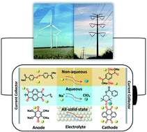

image file: d1ta00528f-p1.tif

Kathryn Holguin

Kathryn Holguin received her Bachelor's degree in 2009 and Master's degree in 2011 from George Mason University. She is currently a PhD candidate under the supervision of Prof. Chao Luo in the Chemistry and Biochemistry Department, George Mason University. Her research interests focus on organic electrode materials for next-generation energy storage devices.

image file: d1ta00528f-p2.tif

Motahareh Mohammadiroudbari

Motahareh Mohammadiroudbari received her B.S. and M.S. in Polymer Engineering from Amirkabir University of Technology and Sahand University of Technology, respectively. She is currently a PhD student in the Department of Chemistry and Biochemistry at George Mason University. Her research interests focus on polymeric structure engineering for sodium-ion and multivalent metal batteries.

image file: d1ta00528f-p3.tif

Kaiqiang Qin

Dr. Kaiqiang Qin obtained his PhD from Tianjin University (China) in 2018. He joined the University of California, Los Angeles (UCLA, USA) as a postdoc from 2018 to 2020. He is currently a postdoc in Prof. Luo's lab at George Mason University (USA). His current research interests focus on next-generation energy storage materials.

image file: d1ta00528f-p4.tif

Chao Luo

Prof. Chao Luo received Bachelor's degree from Wuhan University in 2008. Then, he entered Technical Institute of Chemistry and Physics, Chinese Academy of Sciences and received Master's degree in 2011. After that, he obtained PhD degree at University of Maryland, College Park in 2015 and worked as a postdoc at University of Maryland, College Park from 2016 to 2019. Prof. Luo is currently an assistant professor at George Mason University. His research interests focus on developing new materials and new chemistries for high-performance and sustainable energy storage devices.


1. Introduction

The rapid development of modern technologies, including smart devices, electric vehicles, renewable energy, and grid-scale electrical energy storage, has stimulated a substantial demand for cost-effective and sustainable energy storage devices. State-of-the-art Li-ion batteries (LIBs), consisting of graphite anodes and cobalt-rich cathodes, cannot satisfy this demand because of the high cost and limited availability of lithium resources, as well as the high cost, scarcity, and high toxicity of the cobalt resources.1,2 To overcome these challenges, it is pivotal to exploit advanced battery systems beyond LIBs. Among them, Na-ion batteries (NIBs) have attracted considerable research interests because of the low cost, abundance, and high sustainability of sodium resources.3–6 The fundamental chemical and physical properties of Li, Na, and K elements in various rechargeable battery systems are compared in Table 1. Though the specific/volumetric capacity of Na is lower than Li, the cost of Na is much lower than Li, and the abundance of Na in the earth's crust is three orders of magnitude higher than Li.7 From the overview of different types of metal anodes in rechargeable batteries (Fig. 1), Na shows advantages over Li and K in terms of cost and abundance, which makes Na resources promising for developing cost-effective and sustainable energy storage devices.8 In the last decade, a rich variety of inorganic electrode materials were developed for NIBs, including sodium transition metal oxides, sodium transition metal phosphates, sulfur, selenium, metal sulfides, graphite, tin, phosphorus, hard carbons, etc.9–24 However, compared to lithium ion, sodium ion shows similar chemical/physical properties but a larger ion size and more complicated electrochemistry in NIBs, and thus the electrochemical performance of these inorganic electrode materials in NIBs is not comparable to that in LIBs in terms of specific capacity and cycle life.25,26 The development and applications of cost-effective and sustainable NIBs as next-generation energy storage devices are highly dependent on the performance of advanced electrode materials. Developing low-cost, high-capacity, long-lifetime and high-efficiency electrode materials plays a vital role in the prospect of NIBs.
Table 1 A summary of the fundamental chemical and physical properties of metal elements in various rechargeable battery systems
Atomic mass Ionic radius (Å) E o (V) vs. SHE Volumetric capacity (mA h mL−1) Specific capacity (mA h g−1) Cost (USD kg−1) Abundance in crust (ppm)
Li 6.94 0.76 −3.04 2062 3861 19.2 20
Na 22.99 1.02 −2.713 1129 1166 3.1 23[thin space (1/6-em)]600
K 39.1 1.38 −2.924 610 685 13.1 20[thin space (1/6-em)]900


image file: d1ta00528f-f1.tif
Fig. 1 Overview of the fundamental properties of different types of metal anodes in rechargeable batteries.7,8

The research on sodium batteries initiated in the mid-1960s, when the liquid form of sodium metal was used as a negative electrode in rechargeable batteries at high temperatures (245 °C to 350 °C).27,28 The low cost, lightweight, nontoxicity and abundance of sodium resources stimulated the research on high-temperature sodium–sulfur and sodium–nickel chloride (Zebra) batteries in the last century. However, the commercialization of room-temperature LIBs in the 1990s retarded the development and large-scale applications of high-temperature sodium batteries. Since then, the renaissance of sodium batteries has been dependent on the exploration of room-temperature NIBs.29,30 Due to the success of advanced material synthetic techniques and nanotechnology, the research on room-temperature NIBs thrived in the last decade. Numerous sodium-based energy storage materials and nanostructures were invented to improve the capacity, cycle life, coulombic efficiency, fast charging capability, and energy density of NIBs, whereas the performance of state-of-the-art NIBs is still not comparable with LIBs. To further promote the battery performance, developing advanced electrode materials for NIBs is pivotal.

As universal electrode materials for alkali-ion batteries, organic electrode materials (OEMs) extend their high performance in LIBs to NIBs.31,32 The lightweight, low cost, abundance, high sustainability, and high structural tunability of OEMs enable the rational structure design of cost-effective and sustainable energy storage organic materials for NIBs. To date, there are five types of reaction mechanisms in organic NIBs, including the carbonyl (C[double bond, length as m-dash]O) reaction, imine (C[double bond, length as m-dash]N) reaction, azo (N[double bond, length as m-dash]N) reaction, thioketone/thioester (C[double bond, length as m-dash]S) reaction, and free radical (N–O˙) reaction.33–39Scheme 1 summarizes these five types of reaction mechanisms by using the representative OEMs to illustrate the reversible reaction between OEMs and Na-ions/electrons in each type of reaction mechanism. The conjugated structure plays an essential role in the electrochemical properties of OEMs based on the carbonyl, imine, and thioketone/thioester reactions, enabling intramolecular electron transfer within these conjugated molecules during the reaction between functional groups and Na-ions. Therefore, when designing these OEMs, two or more carbonyl, imine, or thioketone/thioester groups are always connected by a conjugated structure such as a benzene ring to make electrochemically active organic materials. In contrast, the intramolecular electron transfer is not necessary for azo- and free radical-based OEMs, so the structural design can be more flexible. For example, a conjugated structure is not required in free radical-based OEMs.40,41 (2,2,6,6-Tetramethylpiperidin-1-yl)oxidanyl, commonly known as TEMPO, is widely used in designing free radical-based OEMs. The conjugated structure is not necessary for TEMPO-based OEMs. Due to the abundant nature of organic materials, various functional groups and backbone structures can be used to manipulate their electrochemical performance in NIBs.


image file: d1ta00528f-s1.tif
Scheme 1 The reaction mechanisms of various types of organic electrode materials in NIBs.33–39

Though OEMs show great promise in NIBs, there are still three major challenges for their development and applications: (1) low electronic conductivity, which leads to sluggish reaction kinetics; (2) high solubility in the electrolyte, which reduces the cyclic stability; (3) particle pulverization triggered by the large volume change during the sodiation/de-sodiation process, which destroys the structural integrity of organic electrodes and results in poor reaction kinetics and cyclic stability.42–44 To overcome these challenges, a variety of approaches have been adopted to improve the conductivity, stability, and integrity of organic electrodes. For example, a large amount (30 wt% ∼60 wt%) of conductive carbon such as carbon black, graphene, or carbon nanotube, is used to build three-dimensional (3D) conductive networks and enhance the conductivity of the organic electrodes.45–47 Organic salt formation and polymerization of small organic compounds are two effective approaches to tuning the polarity and lipophilicity of OEMs, reducing their solubility in the liquid electrolyte.48–58 To mitigate the particle pulverization in organic electrodes, graphene oxide protection, and self-healing chemistry were used to retain the structural integrity of organic electrodes.43,59 Though great achievements have been obtained, the electrochemical performance of organic NIBs is still not comparable with those of commercial LIBs. The design and synthesis of novel advanced OEMs are demanded for cost-effective and sustainable NIBs. This review summarizes the recent advances in developing high-performance OEMs for non-aqueous, aqueous, and all-solid-state NIBs. The rational structure design principles and future research directions of OEMs in various types of NIBs are also discussed.

2. OEMs for non-aqueous NIBs

OEMs featuring low cost, lightweight, high flexibility, abundant structural diversity, and high recyclability have been extensively studied for non-aqueous NIBs.60–63 To fulfill the goal of cost-effective and sustainable energy storage devices, OEMs that can be derived from biomass or synthesized by natural derivatives, are promising alternatives to inorganic electrode materials in non-aqueous NIBs.64 There are a wide range of organic compounds such as quinones, polyimides, Schiff bases, azo compounds, carboxylates, etc., which have been studied as electrode materials in non-aqueous NIBs.65–67 The focus is to improve their electrochemical reaction kinetics and cycling stability by tailoring their molecular structure, mitigating particle pulverization, and reducing the solubility in the liquid electrolyte. Table 2 summarizes the chemical structure and electrochemical performance of state-of-the-art OEMs in non-aqueous NIBs.
Table 2 Summary of OEMs for non-aqueous NIBsa
Compound Structure Electrolyte Average discharge voltage Initial reversible capacity at current density Cycle life (n) Rate capability
a * The electrochemical performances of the OEMs are collected from the full-cell data, because the half-cell data were not reported.
2DPI126 image file: d1ta00528f-u1.tif 1 M NaClO4 in EC/DEC, 1[thin space (1/6-em)]:[thin space (1/6-em)]1 by volume ∼0.2 V 312 mA h g−1 at 0.1 A g−1 1100 137 mA h g−1 at 10 A g−1
Na2C8H4O4 (ref. 51, 52 and 114) image file: d1ta00528f-u2.tif 1 M NaFSI in EC/DEC, 4[thin space (1/6-em)]:[thin space (1/6-em)]6 0.29 V 282 mA h g−1 at 0.1C 60 ∼150 mA h g−1 at 2C
0.8 M NaClO4 in EC/DEC, 1[thin space (1/6-em)]:[thin space (1/6-em)]1 by volume 0.3 V 295 mA h g−1 at 30 mA g−1 (0.1C) 90 100 mA h g−1 at 10C
1 M NaOTf diglyme ∼0.3 V 245.2 mA h g−1 at 30 mA g−1 N/A 88.2 mA h g−1 at 1 A g−1
DHBQDS50 image file: d1ta00528f-u3.tif 0.8 M NaClO4 in EC/DEC, 1[thin space (1/6-em)]:[thin space (1/6-em)]1 by volume 0.3 V 295 mA h g−1 at 30 mA g−1 (0.1C) 90 100 mA h g−1 at 10C
Na2NDC104 image file: d1ta00528f-u4.tif 1 M NaClO4 in PC + 3 wt% FEC ∼0.3 V 200 mA h g−1 at 0.5C 200 133 mA h g−1 at 5C
CHDA145 image file: d1ta00528f-u5.tif 1.0 M NaClO4 in EC/PC, 1[thin space (1/6-em)]:[thin space (1/6-em)]1 by volume, + 5 wt% FEC ∼0.3 V 307 mA h g−1 at 0.1 A g−1 100 125 mA h g−1 at 2.0 A g−1
NaHBDC54 image file: d1ta00528f-u6.tif 1 M NaPF6 EC/EMC, 3[thin space (1/6-em)]:[thin space (1/6-em)]7 by weight ∼0.34 V 273 mA h g−1 at 10 mA g−1 50 N/A
SSDC68 image file: d1ta00528f-u7.tif 1 M NaClO4 in PC 0.39 V 375 mA h g−1 at 50 mA g−1 400 72 mA h g−1 at 10 A g−1
Na3BTC105 image file: d1ta00528f-u8.tif 1 M NaBF4 in tetraglyme 0.42 V 558 mA h g−1 at 0.2C 1500 ∼210 mA h g−1 at 1C
PTCDA60 image file: d1ta00528f-u9.tif 1 M NaPF6 in EC/DMC, 1[thin space (1/6-em)]:[thin space (1/6-em)]1 by weight ∼0.50 V 436.1 mA h g−1 at 25 mA g−1 300 67.7 mA h g−1 at 2 A g−1
BTAQ107 image file: d1ta00528f-u10.tif 1 M NaBF4 in EC/DEC/DMC, 1[thin space (1/6-em)]:[thin space (1/6-em)]1:1 by volume 0.5 V 275.8 mA h g−1 at 25 mA g−1 100 105.7 mA h g−1 at 200 mA g−1
PCT110 image file: d1ta00528f-u11.tif 1 M NaBF4 in EC/DEC, 1[thin space (1/6-em)]:[thin space (1/6-em)]1 by volume, +10 wt% FEC 0.5 V 133 mA h g−1 at 200 mA g−1 500 ∼40 mA h g−1 at 2 A g−1
TsNiPc@GO127 image file: d1ta00528f-u12.tif 1 M NaPF6 in EC/DMC, 1[thin space (1/6-em)]:[thin space (1/6-em)]1 by volume ∼0.5 V 600 mA h g−1 at 10 mA g−1 100 N/A
PDA61 image file: d1ta00528f-u13.tif 1 M NaPF6 in EC/DEC,1[thin space (1/6-em)]:[thin space (1/6-em)]1 by weight ∼0.5 V 581 mA h g−1 at 50 mA g−1 1024 122 mA h g−1 at 3.2 A g−1
D/A-CON-10 (ref. 67) image file: d1ta00528f-u14.tif 1 M NaClO4 in PC/FEC, 98[thin space (1/6-em)]:[thin space (1/6-em)]2 by weight ∼0.5 V 860 mA h g−1 at 100 mA g−1 150 133 mA h g−1 at 1 A g−1
D/A-CON-16 (ref. 67) image file: d1ta00528f-u15.tif 1 M NaClO4 in PC/FEC, 98[thin space (1/6-em)]:[thin space (1/6-em)]2 by weight ∼0.5 V 880 mA h g−1 at 100 mA g−1 150 245 mA h g−1 at 1 A g−1
SCID@CNT77 image file: d1ta00528f-u16.tif 1 M NaClO4 in EC/PC/FEC, 1[thin space (1/6-em)]:[thin space (1/6-em)]1:0.05 by volume ∼0.5 V 231 mA h g−1 at 50 mA g−1 500 N/A
Cabpdc103 image file: d1ta00528f-u17.tif 1 M NaClO4 in EC/DEC, 1[thin space (1/6-em)]:[thin space (1/6-em)]1 by volume, +5% FEC 0.5 V 434.6 mA h g−1 at 100 mA g−1 100 150 mA h g−1 at 1 A g−1
TBC65 image file: d1ta00528f-u18.tif 1 M NaPF6 in DME 0.55 V 195 mA h g−1 at 50 mA g−1 600 50 mA h g−1 at 400 mA g−1
Oligomeric Schiff bases62 image file: d1ta00528f-u19.tif 1 M NaFSI in Me-THF ∼0.6 V 250 mA h g−1 at C/10 50 ∼30 mA h g−1 at 5C
Oligomeric Schiff bases62 image file: d1ta00528f-u20.tif 1 M NaFSI in Me-THF ∼0.6 V 250 mA h g−1 at C/10 50 ∼50 mA h g−1 at 5C
Na4C10H2O8 (ref. 144) image file: d1ta00528f-u21.tif 1 M NaPF6 in EC/DEC, 1[thin space (1/6-em)]:[thin space (1/6-em)]1 by volume 0.65 V 192.7 mA h g−1 at 20 mA g−1 1000 78 mA h g−1 at 2000 mA g−1
NaPTCDA60 image file: d1ta00528f-u22.tif 1 M NaPF6 in EC/DMC, 1[thin space (1/6-em)]:[thin space (1/6-em)]1 by weight ∼0.7 V 182.3 mA h g−1 at 25 mA g−1 120 N/A
DBD-CMP2 (ref. 116) image file: d1ta00528f-u23.tif 1 M NaBF4 in EC/DMC/EMC, 1[thin space (1/6-em)]:[thin space (1/6-em)]1:1 by volume ∼0.75 V 414 mA h g−1 at 50 mA g−1 100 ∼50 mA h g−1 at 2 A g−1
Polymeric Schiff base53 image file: d1ta00528f-u24.tif 1 M NaFSI in Me-THF ∼0.8 V 360 mA h g−1 at 26 mA g−1 (0.1C) 75 190 mA h g−1 at 1C
DAAQ-COF79 image file: d1ta00528f-u25.tif 1 M NaClO4 in EC/DMC, 1[thin space (1/6-em)]:[thin space (1/6-em)]1 by volume ∼1.0 V 420 mA h g−1 at 100 mA g−1 10[thin space (1/6-em)]000 198 mA h g−1 at 5 A g−1
PI-2 (ref. 140) image file: d1ta00528f-u26.tif 1 M NaClO4 in EC/DEC, 1[thin space (1/6-em)]:[thin space (1/6-em)]1 by volume ∼1.0 V ∼280 mA h g−1 at 0.1 A g−1 1000 69.4 mA h g−1 at 5 A g−1
BCP142 image file: d1ta00528f-u27.tif 1 M NaPF6 in DME ∼1.0 V 480.9 mA h g−1 at 1 A g−1 400 339 mA h g−1 at 10 A g−1
CADS43 image file: d1ta00528f-u28.tif 1 M NaClO4 in EC/DMC, 1[thin space (1/6-em)]:[thin space (1/6-em)]1 by volume ∼1.1 V 293 mA h g−1 at 20 mA g−1 100 N/A
DHBQDS50 image file: d1ta00528f-u29.tif 1 M NaClO4 in FEC/DMC, 1[thin space (1/6-em)]:[thin space (1/6-em)]1 by volume 1.2 V 290 mA h g−1 at 20 mA g−1 300 68 mA h g−1 at 1 A g−1
ADASS76 image file: d1ta00528f-u30.tif 1 M NaPF6 in DEGDME 1.2 V and 1.26 V ∼220 mA h g−1 at 0.2C 1000 71 mA h g−1 at 40C
Na2DBQ139 image file: d1ta00528f-u31.tif 1 M NaClO4 in EC/DMC, 1[thin space (1/6-em)]:[thin space (1/6-em)]1 by volume ∼1.2 V 398 mA h g−1 at 0.1C 300 160 mA h g−1 at 5C
PI-1 (ref. 140) image file: d1ta00528f-u32.tif 1 M NaClO4 in EC/DEC, 1[thin space (1/6-em)]:[thin space (1/6-em)]1 by volume ∼1.2 V ∼500 mA h g−1 at 0.1 A g−1 1000 102 mA h g−1 at 5 A g−1
E-FCTF125 image file: d1ta00528f-u33.tif 1 M NaClO4 in EC/DEC, 1[thin space (1/6-em)]:[thin space (1/6-em)]1 by volume ∼1.2 V 332 mA h g−1 at 0.1 A g−1 200 68 mA h g−1 at 2 A g−1
Na2C10H2N2O4 (ref. 120) image file: d1ta00528f-u34.tif 0.8 M NaPF6 in PC ∼1.2 V ∼230 mA h g−1 at 1 Na/20 h 100 ∼10 mA h g−1 at 5C
AQ26ONa141 image file: d1ta00528f-u35.tif 1 M NaPF6 in DME ∼1.2 V 245 mA h g−1 at 50 mA g−1 2500 139 mA h g−1 at 500 mA g−1
ALP-8 (ref. 101) image file: d1ta00528f-u36.tif 1 M NaPF6 in DEGDME 1.2–1.5 V 315 mA h g−1 at 0.3C 150 42 mA h g−1 at 40C
TQA66 image file: d1ta00528f-u37.tif 1 M NaPF6 in diglyme ∼1.5 V 423.3 mA h g−1 at 100 mA g−1 100 N/A
TSAQ69 image file: d1ta00528f-u38.tif 1 M NaClO4 in EC/DMC, 1[thin space (1/6-em)]:[thin space (1/6-em)]1 by weight ∼1.5 V 395 mA h g−1 at 50 mA g−1 2500 220 mA h g−1 at 1000 mA g−1
Na2PDHBQS/RGO121 image file: d1ta00528f-u39.tif 1 M NaClO4 in TGM ∼1.5 V 179 mA h g−1 at 100 mA g−1 150 147 mA h g−1 at 1 A g−1
DAPT-TFP-CPF124 image file: d1ta00528f-u40.tif 1 M NaPF6 in DME ∼1.6 V 257.5 mA h g−1 at 1 A g−1 1400 100 mA h g−1 at 5000 mA g−1
PAQS109 image file: d1ta00528f-u41.tif 1 M NaTFSI in DOL/DME, 1[thin space (1/6-em)]:[thin space (1/6-em)]1 by volume 1.3 V and 1.76 V 134 mA h g−1 at 100 mA g−1 200 ∼120 mA h g−1 at 1 A g−1
AQDS102 image file: d1ta00528f-u42.tif 1 M NaClO4 in EC/DEC, 1[thin space (1/6-em)]:[thin space (1/6-em)]1 by volume 1.73V and 1.62 V 195 mA h g−1 at 30 mA g−1 100 114 mA h g−1 at 480 mA g−1
DHAQNa111 image file: d1ta00528f-u43.tif 1 M NaClO4 in EC/DMC, 1[thin space (1/6-em)]:[thin space (1/6-em)]1 by volume ∼1.75 V 176 mA h g−1 at 0.1C 100 ∼40 mA h g−1 at 2C
Na2AQ26DS132 image file: d1ta00528f-u44.tif 1 M NaPF6 in DME ∼1.75 V 137 mA h g−1 at 50 mA g−1 1200 N/A
ALX47 image file: d1ta00528f-u45.tif 1 M NaPF6 in DEGDME ∼1.8 V 255 mA h g−1 at 50 mA g−1 N/A N/A
LC47 image file: d1ta00528f-u46.tif 1 M NaPF6 in DEGDME ∼1.8 V ∼222 mA h g−1 at 50 mA g−1 N/A N/A
Na4DHTPA78 image file: d1ta00528f-u47.tif 1 M NaClO4 in EC/DMC, 1[thin space (1/6-em)]:[thin space (1/6-em)]1 by volume 1.8 V 223 mA h g−1 at 19 mA g−1 (C/10) 100 ∼190 mA h g−1 at 37.4 mA g−1 (0.2C)
UP113 image file: d1ta00528f-u48.tif 1 M NaBF4 in DME 1.8 V 148.3 mA h g−1 at 100 mA g−1 1000 91.8 mA h g−1 at 3 A g−1
OAP113 image file: d1ta00528f-u49.tif 1 M NaBF4 in DME 1.8 V 137.8 mA h g−1 at 100 mA g−1 1000 107.8 mA h g−1 at 3 A g−1
PDI-Ur108 image file: d1ta00528f-u50.tif 1 M NaClO4 in EC/DEC, 1[thin space (1/6-em)]:[thin space (1/6-em)]1 molar ratio 1.9 V 119 mA h g−1 at 25 mA g−1 50 ∼112 mA h g−1 at 200 mA g−1
Na2C6O6 (ref. 59 and 70) image file: d1ta00528f-u51.tif 1 M NaClO4 in FEC/EC/DMC, 2[thin space (1/6-em)]:[thin space (1/6-em)]3:5 by volume ∼2.0 V 205 mA h g−1 at 20 mA g−1 500 ∼102 mA h g−1 at 1 A g−1
Na2C6O6 (ref. 59 and 70) image file: d1ta00528f-u52.tif 0.6 M NaPF6 in DEGDME ∼2.0 V 484 mA h g−1 at 50 mA g−1 50 371 mA h g−1 at 1 A g−1
Ni-TTO63 image file: d1ta00528f-u53.tif 1 M NaPF6 in DME ∼2.0 V 155 mA h g−1 at 0.1 A g−1 100 118 mA h g−1 at 5 A g−1
PHATN71 image file: d1ta00528f-u54.tif 4 M NaPF6 in DME 2.12 V 251 mA h g−1 at 50 mA g−1 50[thin space (1/6-em)]000 105 mA h g−1 at 25C
TQBQ-COF72 image file: d1ta00528f-u55.tif 1 M NaPF6 in DEGDME 2.2 V 452 mA h g−1 at 20 mA g−1 1000 134.3 mA h g−1 at 10 A g−1
PTCDA60,73 image file: d1ta00528f-u56.tif 1 M NaClO4 in PC ∼2.2 V ∼135 mA h g−1 at 100 mA g−1 500 76 mA h g−1 at 71C
PT75 image file: d1ta00528f-u57.tif 0.3 M Na[TFSI]/ILs ∼2.2 V 301 mA h g−1 at 20 mA g−1 100 ∼180 mA h g−1 at 300 mA g−1
NTCDA115 image file: d1ta00528f-u58.tif 1 M NaClO4 in EC/DMC/EMC, 1[thin space (1/6-em)]:[thin space (1/6-em)]1:1 by volume, + 2% FEC 2.2 V 157 mA h g−1 at 100 mA g−1 500 112 mA h g−1 at 1 A g−1
PI143 image file: d1ta00528f-u59.tif 1 M NaPF6 in EC/DMC, 1[thin space (1/6-em)]:[thin space (1/6-em)]1 by volume ∼2.2 V 207 mA h g−1 at 200 mA g−1 100 39 mA h g−1 at 500 mA g−1
PTCDA138 image file: d1ta00528f-u60.tif 1 M NaPF6 in EC/DEC, 1[thin space (1/6-em)]:[thin space (1/6-em)]1 by volume ∼2.2 V 140 mA h g−1 at 10 mA g−1 300 91 mA h g−1 at 1000 mA g−1
PI2 (ref. 137) image file: d1ta00528f-u61.tif 1 M NaPF6 in EC/DMC, 1[thin space (1/6-em)]:[thin space (1/6-em)]1 by weight ∼2.2 V 148.9 mA h g−1 at 0.1C 5000 50 mA h g−1 at 40C
TAPQ123 image file: d1ta00528f-u62.tif 4 M NaTFSI in TEGDME ∼2.2 V ∼250 mA h g−1 at 0.5C NA NA
PYT-TABQ/rGO129 image file: d1ta00528f-u63.tif 1 M NaPF6 in DME ∼2.2 V ∼210 mA h g−1 at 1 A g−1 1400 141.5 mA h g−1 at 8 A g−1
PPTS122 image file: d1ta00528f-u64.tif 1 M NaPF6 in DME 1.2–2.4 V 290 mA h g−1 at 1 A g−1 2000 155 mA h g−1 at 10 A g−1
P5Q74 image file: d1ta00528f-u65.tif 1 M NaClO4 in EC/DMC/FEC 2.5 V 418 mA h g−1 at 0.1C 300 201 mA h g−1 at 1C
C4Q75 image file: d1ta00528f-u66.tif 0.3 M Na[TFSI]/ILs ∼2.5 V 406 mA h g−1 at 20 mA g−1 300 343 mA h g−1 at 45 mA g−1
BPOE56 image file: d1ta00528f-u67.tif 1 M NaClO4 in PC ∼2.5 V ∼200 mA h g−1 at 10 mA g−1 7000 ∼40 mA h g−1 at 5 A g−1
Q-TTF-Q130 image file: d1ta00528f-u68.tif 2.5 M NaTFSI in PC 2.6 V 232 mA h g−1 at 40 mA g−1 10 N/A
PP-PS135 image file: d1ta00528f-u69.tif 1 M NaPF6 in EC/DEC, 1[thin space (1/6-em)]:[thin space (1/6-em)]1 by volume ∼3.15 V 75 mA h g−1 at 40 mA g−1 350 N/A
PDPPD128 image file: d1ta00528f-u70.tif 0.5 M NaPF6 in EC/PC, 1[thin space (1/6-em)]:[thin space (1/6-em)]1 by volume 3.38V 94 mA h g−1 at 1C 1000 ∼35 mA h g−1 at 100C
PVK-3 (ref. 131) image file: d1ta00528f-u71.tif 1 M NaPF6 in EC/DEC, 1[thin space (1/6-em)]:[thin space (1/6-em)]1 by volume 3.4 V 110 mA h g−1 at 50 mA g−1 900 33 mA h g−1 at 500 mA g−1
Ppy/DS133 image file: d1ta00528f-u72.tif 1 M NaPF6 in EC/DEC, 1[thin space (1/6-em)]:[thin space (1/6-em)]1 by volume ∼3.5 V 115 mA h g−1 at 50 mA g−1 70 85 mA h g−1 at 50 mA g−1
OPr136 image file: d1ta00528f-u73.tif 1 M NaClO4 in PC ∼3.5 V 121 mA h g−1 at 20 mA g−1 50 10 mA h g−1 at 500 mA g−1
PTPAn134 image file: d1ta00528f-u74.tif DOL/DME, 1[thin space (1/6-em)]:[thin space (1/6-em)]1 by volume, Saturated with NaPF6 ∼3.6 V 98 mA h g−1 at 50 mA g−1 200 88 mA h g−1 at 20C
DCBQ106 image file: d1ta00528f-u75.tif 1 M NaBF4 in PC N/A 175.8 mA h g−1 at 10 mA g−1 1000 82.1 mA h g−1 at 200 mA g−1


2.1 Molecular structure design

The extension of π conjugated structures is a feasible strategy to improve the electrochemical reaction kinetics and achieve the fast-charging capability of OEMs in non-aqueous NIBs. The conjugated structure is able to stabilize the charged/discharged states while facilitating ion diffusion. Wang et al. synthesized (sodium 4,4-stilbene-dicarboxylate) SSDC through a one-pot eco-friendly reaction (Fig. 2a), offering an extended π-conjugation linkage between two carboxylate groups.68 The SSDC anodes were tested in half cells with the sodium metal as a counter electrode at high current densities to evaluate the capacity and cycle life. The SSDC anode delivered a specific capacity of 247 mA h g−1 at 1 A g−1 in the first cycle with an initial coulombic efficiency of 80% (Fig. 2b). The coulombic efficiency was enhanced to 98% after 5 cycles while the capacity stabilized at 160 mA h g−1. After 400 cycles, a reversible capacity of 112 mA h g−1 was retained with capacity retention higher than 70%, demonstrating exceptional cycle life at a high current density. Moreover, the SSDC anode delivered reversible capacities of 105 mA h g−1 at 2 A g−1 and 72 mA h g−1 at 10 A g−1, demonstrating fast-charging capability in non-aqueous NIBs. This superior high-rate performance is attributed to the extended π-conjugation structure, which not only improves the charge transport and stabilizes the charged/discharged states but also enhances the intermolecular interaction and the resulting terrace packing structure.
image file: d1ta00528f-f2.tif
Fig. 2 (a) Schematic diagram for the synthesis and reversible Na-ion insertion/extraction mechanism of SSDC. (b) Cyclability of SSDC (black, the rate capability of Super-P (blue) and SBDC (red) are also presented for comparison) under a current density of 1 A g−1. Reproduced with permission.68 Copyright 2015 American Chemical Society. (c) Design of β-ketoenamine-linked compound-based organic electrode. Chemical structure of TSAA and TSAQ. (d) Rate performance of TSAA and TSAQ electrodes at various current densities. (e) Cycle performance and the corresponding coulombic efficiency of TSAQ at a current density of 1000 mA g−1 in the voltage range of 3–0.05 V for more than 2500 cycles. Reproduced with permission.69 Copyright 2016 Springer Nature. (f) A schematic of the proposed de/sodiation mechanism of Na2C6O6. During charging, the structural change from the α-to the γ-phase is kinetically suppressed. This leads to a premature desodiation, which results in limited sodium storage in subsequent cycles. Nevertheless, the reversible phase transformation becomes possible by decreasing the particle size and selecting a proper electrolyte, which in turn facilitates ideal four-sodium storage in Na2C6O6. (g) Rate capability and corresponding cycle performance (inset) of Na2C6O6 electrodes from 0.5–3.3[thin space (1/6-em)]V. (h) Voltage profiles of Na2C6O6 electrodes with high active content (80% Na2C6O6, 5.3 mg cm−2) and high mass loading (60% Na2C6O6, 20 mg cm−2) compared with the original condition (60% Na2C6O6, 3 mg cm−2). Reproduced with permission.70 Copyright 2017 Macmillan Publishers Limited.

Another strategy to improve the electrochemical performance of OEMs in non-aqueous NIBs is stabilizing α-C intermediate radicals by the resonance and steric effects. The highly reactive α-C radicals are formed in OEMs during the sodiation/de-sodiation process, triggering undesired side reactions and thus reducing the electrochemical performance. To design a stabilized α-C radical intermediate, Wu et al. fabricated highly stable tri-carbonyl-based anodes by diminishing the reactivity of radical intermediates.69 Tris N-salicylideneanthramine, TSAA, and tris N-salicylideneanthraqunoylamine, TSAQ, were synthesized by a facile metallic catalyst-free condensation reaction (Fig. 2c). The carbonyl group (C[double bond, length as m-dash]O) in TSAA and TSAQ could undergo the electron reduction, leading to the breakage of the tri-β-ketoenamine system and the formation of a benzyl radical (α-C radical) intermediate. Subsequently, the resonance effect of the aromatic ring structures together with the steric hindrance of the large-size substitution groups in TSAA and TSAQ was able to stabilize the benzyl radical intermediate. The reversible specific capacities of 172 mA h g−1 and 366 mA h g−1 were achieved for TSAA and TSAQ at 50 mA g−1, respectively, suggesting ∼5.5 and ∼11.5 Na+ per molecule could participate in the electrochemical redox reactions. More importantly, TSAQ delivered a high-rate performance of 220 mA h g−1 at 1000 mA g−1 (Fig. 2d) and showed no obvious capacity degradation after 2500 cycles (Fig. 2e), demonstrating excellent rate capability and cycle life. This work provided a structure design strategy to stabilize the α-C radical intermediate formed in organic anodes during the sodiation/de-sodiation process, which may also be beneficial for the structure design of other organic energy storage systems.

In addition to these organic anodes, the structure design for organic cathodes in non-aqueous NIBs is also significant. Lee et al. studied the four-sodium ion storage mechanism of disodium rhodizonate (Na2C6O6) as one of the best candidates for cathodes in NIBs.70 The redox mechanism of disodium rhodizonate is demonstrated in Fig. 2f. The α-phase of Na2C6O6 transfers into γ-phase due to the thermodynamic preference. The removal of sodium ions during the charge mitigates the reverse structural change, leading to permanent desodiation. As a result, the charged electrode remains as partially sodiated intermediate (Na2+xC6O6) in γ-phase. The research suggested the redox capability can be significantly improved by reducing the particle size and selecting a good electrolyte. The selected electrolyte, diethylene glycol dimethyl ether (DEGDME), could diminish the cation–anion interactions and result in the most efficient phase transformation. The four-electron process in the Na-ion cell was evaluated at a large potential window of 0.5–3.2 V. The nanoparticle electrode (Nano/DEGDME) revealed a reversible capacity of 498 mA h g−1 at 50 mA g−1, which is about 95% of the theoretical capacity as shown in Fig. 2g. Even with an increased mass loading of up to 20 mg cm−2, Na2C6O6 still retained a reversible capacity of 428 mA h g−1 along with an areal capacity of 8.56 A h cm−2 (Fig. 2h), demonstrating great promise for practical applications. The complete utilization of organic cathodes at high mass loading offers opportunities for developing cost-effective and sustainable organic NIBs.

The polymeric structure design for OEMs can also affect the electrochemical performance in non-aqueous NIBs. Mao et al. suggested hexaazatrinaphthalene (HATN), which contains imine functional groups with a high theoretical capacity of 418 mA h g−1, to be used as a cathode for non-aqueous NIBs.71 By polymerizing this organic compound, the more stable PHATN was obtained which was not only used in NIBs but also in multivalent (Mg and Al) rechargeable batteries. The simulated geometry and insertion potential versus Na/Na+ for Nam(HATN)n was calculated by density functional theory (DFT), and the discharge voltage profile was found in different ratios (Fig. 3a). The rate capability and cycle life of PHATN in 4 M NaPF6/dimethoxyethane (DME) electrolyte were tested in NIBs with sodium metal as the counter electrode. As shown in Fig. 3b, a small capacity decrease from 220 mA h g−1 to 164 mA h g−1 was observed with elevated current density from C/8 to 5C. Even at high current densities of 12C and 25C, PHATN still retained the reversible capacities of 138 mA h g−1 and 105 mA h g−1, respectively, and an ultra-long cycle life of 50[thin space (1/6-em)]000 cycles was achieved at 25C with 83.8% capacity retention (Fig. 3c), indicating the fast reaction kinetics and stable cyclic stability. The excellent electrochemical performance of PHATN makes it a promising cathode for rechargeable batteries. In addition to PHATN, covalent–organic frameworks (COFs) with porous structures while containing active groups such as C[double bond, length as m-dash]O and C[double bond, length as m-dash]N offer redox sites for sodium-ion storage. The size of pores is very important, and it should be adjusted based on the size of sodium ions to make the ion transport facile and efficient. The synthesis of triquinoxalinylene and benzoquinone (TQBQ) by using a triple condensation reaction between tetraminophenone and cyclohexanehexone yielded a new COF skeleton to be used in NIBs.72 The carbonyl groups provide multiple redox sites to store up to 12 Na+, while pyrazine groups link the building blocks in TQBQ-COF two-dimensional structures (Fig. 3d). The reaction mechanism was exploited by characterizing the corresponding absorption peaks for the active groups (C[double bond, length as m-dash]O/C[double bond, length as m-dash]N) during charge and discharge using in situ Fourier-transform infrared spectroscopy (FTIR, Fig. 3e), confirming that carbonyl groups and imine groups are redox-active centers to reversibly react with Na-ions and electrons. The TQBQ-COF-based electrode delivered a high capacity of 452.0 mA h g−1 at 0.02 A g−1 (Fig. 3f) and high cycling stability of ∼96% capacity retention after 1000 cycles at a high current density of 1.0 A g−1 (Fig. 3g). The honeycomb-like morphology of the insoluble TQBQ-COF combined with doped nitrogen improved the electronic conductivity and ion/electron transport. The porous architecture of nitrogen-rich COFs promises high-power NIBs.


image file: d1ta00528f-f3.tif
Fig. 3 (a) Optimized geometries and insertion potentials vs. Na/Na+ of the Nam(HATN)n complexes surrounded by implicit solvent from DFT calculations using M05-2X/6-31+G(d,p) and PBE-GD3/6-31+G(d,p) DFT calculations. (b) Rate capability at various current densities from C/8 to 25C. (c) Long-term cycling performance of PHATN under the current densities of 10 A g−1 (25C) for 50[thin space (1/6-em)]000 cycles. Reproduced with permission.71 Copyright 2019 Wiley-VCH Verlag GmbH & Co. KGaA. (d) The chemical structure and possible electrochemical redox mechanism of TQBQ-COF with a theoretical capacity of 515 mA h g−1. (e) In situ FTIR spectra collected at different states. (f) Charge–discharge profiles of the TQBQ-COF electrode at 0.02 A g−1. (g) Long cycling stability of TQBQ-COF electrodes at different current densities (0.1, 0.5, and 1.0 A g−1). The capacities are all calculated based on the mass of TQBQ-COF. Reproduced with permission.72 Copyright 2020 Springer Nature.

2.2 Particle pulverization mitigation

The large volume change during cycling is another existing challenge for high-energy NIBs. Luo et al. developed two approaches to overcome this challenge: (1) wrapping OEMs with graphene oxide to accommodate the volume change and mitigate particle pulverization;43 (2) employing self-healing chemistry to suppress the resulting mechanical fracture by establishing connections between the polymer binder and active material.59 In the first approach, graphene oxide wrapped croconic acid disodium salt (CADS) was designed and synthesized.43 The particle pulverization of CADS was alleviated by graphene oxide, resulting in an improved reversible capacity and cycle life. In the second approach, sodium rhodizonate dibasic (SRD) was used as a model to study the self-healing chemistry between the active material and the polymer binder in non-aqueous NIBs.59 Although SRD contains the highest number of oxygen atoms among organic electrodes (Fig. 4a), it undergoes pulverization caused by large volume expansion. The two of carbonyl groups in fully sodiated SRD could form hydrogen bonds with hydroxyl-rich binders. Sodium alginate (SA) as a hydroxyl-rich binder and polyvinylidene fluoride (PVDF) as a hydroxyl-free binder were chosen to demonstrate the self-healing chemistry between the electrode material and the binder (Fig. 4b). FTIR spectra confirmed the formation of hydrogen bonds, which results in the deformation of pyranose rings in the SA binder. This was confirmed by the disappearance of the FTIR peak at ∼1300 cm−1 for the SRD-SA film. To investigate the role of the binder, the electrochemical performance of SRD with the SA binder and the PVDF binder was compared. As shown in Fig. 4c and d, SRD-SA electrodes showed much better cycle life of 500 cycles and higher rate capability up to 1 A g−1 in non-aqueous NIBs due to the self-healing chemistry between SRD and the SA binder. This work opened a new door for the application of self-healing chemistry in rechargeable batteries.
image file: d1ta00528f-f4.tif
Fig. 4 (a) The sodiation–desodiation mechanism for SRD. (b) Schematic illustration of hydrogen bonding between SRD and SA. (c) Cycle life of the SRD-PVDF and SRD-SA electrodes at a current density of 50 mA g−1. (d) Rate capability of the SRD-SA and SRD-PVDF electrodes. Reproduced with permission.59 Copyright 2017 Elsevier Inc.

2.3 Dissolution inhibition

Due to the high solubility of OEMs in the liquid electrolyte, their dissolution induces fast active material loss and capacity decline in non-aqueous NIBs. Several strategies such as surface coating, carbon encapsulation, electrolyte optimization, organic salt formation, and polymerization have been used to mitigate the dissolution of OEMs. Recently, surface modification at the atomic level was introduced as an effective strategy to stabilize organic electrodes. Zhao et al. and Luo et al. used a gas-phase atomic layer deposition (ALD) technique to deposit a thin layer (2–5 nm) of Al2O3 on the surface of disodium terephthalate and 2,5-dihydroxy-1,4-benzoquinone disodium salt electrodes to improve their cyclic stability in non-aqueous NIBs.50 The Al2O3 coating acts as an artificial solid electrolyte interphase (SEI) layer to protect the organic electrode from dissolution into the liquid electrolyte and enhance the electrochemical performance. Thangavel et al. also applied ultrathin metal oxide coatings on the surface of perylene-3,4,9,10-tetracarboxylicacid dianhydride (PTCD) via the ALD technique.73 Two of the carbonyl groups in PTCD act as active centers to reversibly react with Na-ions and electrons (Fig. 5a). The metal oxide coatings (Al2O3, ZnO, and TiO2) can form a stable interphase to protect the PTCD electrodes from dissolution and improve the electrochemical kinetics and cyclic stability of PTCD electrodes. All the coated electrodes showed better cycle life and higher rate capability than the pristine electrodes, because the PTCD dissolution in the organic electrolyte was mitigated by the coating layer (Fig. 5b and c). The PTCD electrode coated with TiO2 (Ti-PTCD) exhibited better electrochemical performance than the other two coatings (Al2O3 and ZnO) in terms of rate capability and cycle life. The Ti-PTCD electrode showed a stable cycle life and low polarization for 500 cycles. These results demonstrated that surface modification is an effective method to enhance the interphase stability and cycle life of organic electrodes.
image file: d1ta00528f-f5.tif
Fig. 5 (a) Sodium-ion storage mechanism in a PTCD organic molecule. (b) Cyclic stability for different metal oxide-coated (2 cycles) PTCD samples at 18C (2.5 A g−1). (c) Rate performance of PTCD, and metal oxide-coated PTCD (2 cycles). Reproduced with permission.73 Copyright 2020 Wiley-VCH GmbH. (d) Schematic of the discharge–charge of P5Q cathode and sodium-metal anode. During the discharge, electrons in sodium metal lose and pass through the separator to reach P5Q. At the same time, the carbonyl groups gain electrons and sodium ions are embedded in the carbonyl groups of P5Q. The charging process is the opposite way. (e) Discharge capacities of P5Q and P5Q/CMK-3 at 0.1C and coulombic efficiency of P5Q/CMK-3 (1[thin space (1/6-em)]:[thin space (1/6-em)]2). Reproduced with permission.74 Copyright 2019 American Chemical Society. (f) Chemical structures of six ionic liquids in this study. (g) Schematic comparison of polarity, donor ability, and quinone-solvent interactive energy for DME and ionic liquids. (h) Cycling stability of C4Q cathode at 130 mA g−1 (0.29C) in 0.3 M Na[TFSI]/DME and 0.3 M Na[TFSI]/[PY13][TFSI] electrolyte. The cathode consists of 50 wt% C4Q, 40 wt% conducting carbon, and 10 wt% binder. Reproduced with permission.75 Copyright 2018 Elsevier Inc.

Quinone-based organic electrodes have been widely studied in non-aqueous NIBs due to their low cost, abundance, and high sustainability. However, the quinone derivatives also suffer from high solubility in the liquid electrolyte. To circumvent this challenge, the composite structure of Pillar[5]quinone (P5Q) was built by encapsulating P5Q in ordered mesoporous carbon (CMK-3) and single-walled carbon nanotubes (SWCNT).74 Xiong et al. further introduced poly(ethylene glycol) (PEG) as a gel polymer electrolyte to restrain the solubility of P5Q. The discharge–charge mechanism of the P5Q cathode is illustrated in Fig. 5d, indicating that carbonyl groups play an important role in the redox reaction with Na-ions and electrons. The large surface area of CMK-3 allows better diffusion and absorption of sodium ions while SWCNTs are beneficial in creating a 3D conductive network around the P5Q. The initial capacity of 418 mA h g−1 at 0.1C was achieved for the P5Q/CMK-3/SWCNT cathode, and a reversible capacity of 290 mA h g−1 was retained after 300 cycles (Fig. 5e), demonstrating superior cycling stability. Furthermore, P5Q/CMK-3 with a ratio of 1[thin space (1/6-em)]:[thin space (1/6-em)]2 delivered higher rate capability and better cycle life than pure P5Q and P5Q/CMK-3 with a ratio of 1[thin space (1/6-em)]:[thin space (1/6-em)]1 in non-aqueous NIBs, suggesting that a higher content of CMK-3 could reduce capacity decay and stabilize the cathode. The P5Q/CMK-3 composites represent a promising structure for stabilizing organic cathodes in non-aqueous NIBs.

The effort to improve the stability of quinone-based cathodes has not been limited to structure optimization. Selecting the best electrolyte with adjustable physicochemical properties such as weaker polarity and lower donor numbers is another method to enhance the performance of organic cathodes.75 Among various organic electrolytes, ionic liquids (ILs) have been exploited in non-aqueous NIBs based on organic quinone cathodes. In general, ILs were composed of cations such as N-methyl-N-propylpyrrolidinium [PY13], N-butyl-N-methylpyrrolidinium [PY14], and N-methyl-N-propyl piperidinium [PP13], and anions such as bis(fluorosulfonyl)imide [FSI] and bis(trifluoromethanesulfonyl)imide [TFSI] (Fig. 5f). Wang et al. evaluated the performance of five types of para-quinone small molecules including 1,4-benzoquinone (p-BQ), 4,4′-dimethyl-1,1′-bi(cyclohexa-3,6-diene)-2,2′,5,5′-tetraone (DBT), 9,10-anthraquinone (AQ), 5,7,12,14-pentacenetetrone (PT), Calix[4]quinone (C4Q) in non-aqueous NIBs. The inhibitory effect of different ILs toward the dissolution of quinone electrode materials is shown in Fig. 5g. Weaker polarity, lower donor number of ILs, and small interaction energy between the active material and ILs suppress the dissolution of OEMs in the electrolyte. The interaction energy between quinone cathodes and ILs was calculated using DFT. According to the results, [PY13][TFSI]–p-BQ and [PY14][FSI]–p-BQ showed the smallest and largest interaction energy, respectively. Therefore, [PY13][TFSI], in which p-BQ has the lowest solubility, was selected for the electrochemical test. As shown in Fig. 5h, the [PY13][TFSI] based electrolyte in the Na/C4Q cell exhibited a much better cycle life (300 cycles) than the DME-based electrolyte, demonstrating that developing ILs-based electrolytes is a promising method to address the dissolution challenge of OEMs in non-aqueous NIBs.

In addition to surface coating, carbon encapsulation, and electrolyte optimization, organic salt formation and polymerization of small organic molecules are also effective strategies to overcome the dissolution challenge of OEMs in the electrolytes. A novel azo group based organic anode was designed by Luo et al.76 The azo compounds with and without carboxylate groups in Fig. 6a showed different electrochemical behaviors in non-aqueous NIBs because of the dissolution of azo compounds. Azobenzene (AB) without a carboxylate group is highly soluble in the electrolyte and suffers from very fast capacity fading, while 4-(phenylazo)benzoic acid sodium salt (PBASS) with one carboxylate group attached to azobenzene shows improved cyclic stability. Azobenzene-4,4′-dicarboxylic acid sodium salt (ADASS) with two carboxylate groups exhibited the best electrochemical performance (Fig. 6b and c) in terms of fast charging capability (up to 40C) and long cycle life (2000 cycles). The carboxylated azo compounds represent a new family of organic anodes for high-performance NIBs. Another example of organic salts in non-aqueous NIBs is sodium 5,5′-carbonylbis(isobenzofuran-1,3-dione) (SCID) synthesized from two sodium phthalate bridged by carbonyl groups.77 The structure and mechanism of Na ion insertion/extraction in SCID is illustrated in Fig. 6d. The bridging carbonyl group is able to activate the adjacent carbonyl groups in SCID, accommodating four sodium ions and leading to a high initial capacity of 231 mA h g−1 at 50 mA g−1. At a higher current density of 100 mA g−1, an initial capacity of 155 mA h g−1 is achieved, and a reversible capacity of 83 mA h g−1 can still be retained after 500 cycles (Fig. 6e). This work confirmed that organic salt formation is an effective strategy to overcome the high solubility challenge of OEMs in non-aqueous NIBs.


image file: d1ta00528f-f6.tif
Fig. 6 (a) Molecular structure of AB, PBASS, and ADASS. (b) Rate performance at various C-rates. (c) De-sodiation capacity and coulombic efficiency versus cycle number at 20C. Reproduced with permission.76 Copyright 2018 Wiley-VCH Verlag GmbH & Co. KGaA. (d) The proposed mechanism of Na ion insertion/extraction into/from the molecular structure of SCID. Electrochemical performance of SCID/Na half cells in the voltage range of 0.01–3.0 V. (e) Cycling performance of SCID@CNT at current densities of 100 mA g−1. Reproduced with permission.77 Copyright 2020 The Royal Society of Chemistry. (f) Electrochemical redox reaction mechanism of Na+ ions with Na4C8H2O6/Na6C8H2O6 and Na2C8H2O6/Na4C8H2O6 at potentials of 0.3 V and 2.3 V, respectively. (g) Galvanostatic charge/discharge voltage profiles of the full cells assembled with Na4DHTPA under a current density of 19 mA g−1. (h) Cycling and coulombic efficiency under a current density of 19 mA g−1. Reproduced with permission.78 Copyright 2014 Wiley-VCH Verlag GmbH & Co. KGaA. (i) Synthetic route and simulated structures of DAAQ-COF and illustration of the Layer-by-Layer Stacking in 2D-COF with different thickness. Reproduced with permission.79 Copyright 2019 American Chemical Society.

To use OEMs as both the cathode and anode in all-organic batteries for high-sustainability energy storage devices, Wang et al. developed a unique organic salt, organic tetrasodium salt of 2,5-dihydroxyterephtalic acid (Na4C8H2O6) with enolate and carboxylate groups.78 The redox couples of Na2C8H2O6/Na4C8H2O6 at 2.3 V in the positive electrode and Na4C8H2O6/Na6C8H2O6 at 0.3 V in the negative electrode were employed in the all-organic NIBs. The reaction mechanism is shown in Fig. 6f, indicating the alkoxide groups act as active centers in the positive electrode and carboxylate groups act as active centers in the negative electrode. The conjugated benzene ring, combined with both types of functional groups, stabilizes the redox intermediates in the electrochemical process. The excellent performance of Na4C8H2O6 in the symmetric full cell was confirmed by various electrochemical tests. In the cutoff window from 0.2 V to 2.6 V, the full cell delivered high charge and discharge capacities of 223 mA h g−1 and 198 mA h g−1 with an average discharge voltage of ∼1.8 V (Fig. 6g). In addition, the full cell was stably tested for 100 cycles with the coulombic efficiency close to 99% (Fig. 6h), demonstrating great promise for high-sustainability NIBs. Therefore, organic salt formation is an effective strategy to overcome the high solubility challenge of OEMs and achieve high-performance organic cathodes and anodes for non-aqueous NIBs.

As is well known, the solubility of organic compounds decreases as their molecular weight increases. Hence, redox-active polymers are widely used in non-aqueous NIBs to solve the high solubility challenge. As previously discussed, COFs with crystalline structures and π-conjugated skeletons can offer high electrochemical performance in non-aqueous NIBs. To gain fundamental understanding of electrochemical behaviors of COFs, facile synthesis of β-ketoenamine linked DAAQ-COF from 1,3,5-triformylphloroglucinol was used to prepare the two dimensional (2D)-COFs with different thicknesses (Fig. 6i).79 The effect of thickness on the electrochemical performance of COFs was investigated at different conditions. The results demonstrated a lower thickness is more favorable in improving the capacity and cyclic stability. The high capacity of 420 mA h g−1, excellent rate capability of 198 mA h g−1 at a high current density of 5 A g−1, and outstanding cycling stability (10[thin space (1/6-em)]000 cycles) for the DAAQ-COF with a thickness of 4–12 nm confirm that the thin 2D-COFs are promising for non-aqueous NIBs. Further studies can be done to design an exfoliated structure of COFs, where the thickness remains low enough for high-rate electrochemical reactions in non-aqueous NIBs. Therefore, based on the knowledge gained from the recent progress of OEMs in non-aqueous NIBs, more research efforts could be devoted to the rational design of molecular structures, organic electrolytes, interphase layers, hybrid composites, and polymeric frameworks to further optimize the electrochemical performance of OEMs in non-aqueous NIBs.

3. OEMs in aqueous NIBs

Aqueous NIBs are promising alternatives to LIBs due to their high affordability, sustainability, and environmental benignity. However, their performance was limited by the narrow electrochemical stability window of aqueous electrolytes due to electrochemical water splitting at high and low potentials.80 Many high-performance electrode materials such as graphite, silicon, sodium metal, hard carbons, and sodium transition metal oxides do not show good performance in aqueous NIBs. It is of great significance to develop high-performance electrode materials for aqueous NIBs. Here, the tunable molecular structure and adjustable redox potentials make OEMs promising electrode materials for aqueous NIBs.81–83 A number of high-performance OEMs compatible with aqueous battery systems have been explored and are presented in this section, including carbonyl compounds and imine compounds. Table 3 summarizes the chemical structure and electrochemical performance of state-of-the-art OEMs in aqueous NIBs.
Table 3 Summary of OEMs for aqueous NIBsa
Compound Structure Electrolyte Average discharge voltage Initial reversible capacity at current density Cycle life (n) Rate capability
a *The electrochemical performances of the OEMs are collected from the full-cell data, because the half-cell data were not reported.
PTCDI112* image file: d1ta00528f-u76.tif 1 M Na2SO4 aqueous electrolyte −0.5 V vs. Ag/AgCl 357 F g−1 at 200 mA g−1 1000 103 F g−1 at 9 A g−1
PPTO86* image file: d1ta00528f-u77.tif 5 M NaNO3 in H2O ∼0 V 201 mA h g−1 at 1C 80 N/A
NatMel-Na118 image file: d1ta00528f-u78.tif 1 M Na2SO4 in H2O ∼0.1 V vs. MSE 30.4 ± 1.6 mA h g−1 at 10 mA g−1 30 N/A
SynMel-Na118 image file: d1ta00528f-u79.tif 1 M Na2SO4 in H2O ∼0.15 V vs. MSE 31.1 ± 2.0 mA h g−1 at 10 mA g−1 30 N/A
E-SynMel-Na118 image file: d1ta00528f-u80.tif 1 M Na2SO4 in H2O ∼0.2 V vs. MSE 24.1 ± 2.0 mA h g−1 at 10 mA g−1 30 N/A
MNV94* image file: d1ta00528f-u81.tif 2.5 M NaClO4 in H2O ∼0.4 V 63 mA h g−1 at 0.3 A g−1 700 ∼50 mA h g−1 at 2.4 A g−1
PNTCDA91* image file: d1ta00528f-u82.tif 1 M Na2SO4 in H2O ∼0.5 V 134.4 mA h g−1 at 10C 1000 112 mA h g−1 at 1.8 A g−1
Polyimide90* image file: d1ta00528f-u83.tif 5 M NaNO3 in H2O ∼0.6 V 184 mA h g−1 at 500C 20 N/A
4-HT-Benzene88* image file: d1ta00528f-u84.tif 8 M NaClO4 in H2O ∼0.6 V vs. SCE 52 mA h g−1 at 0.075 A g−1 100 ∼62 mA h g−1 at C/10
PTAm119 image file: d1ta00528f-u85.tif 0.1 M NaBF4 in H2O 0.66 V vs. Ag/AgCl 114 mA h g−1 at 60C 1000 N/A
PNZ93* image file: d1ta00528f-u86.tif 10 M NaOH in H2O ∼0.7 V 277 mA h g−1 at 0.5 A g−1 1500 92 mA h g−1 at 30 A g−1
PNP89* image file: d1ta00528f-u87.tif 1 M Na2SO4 in H2Oat pH 7 ∼0.8 V 132.2 mA h g−1 at 10C 500 92 mA h g−1 at 20C
PNTCDA92* image file: d1ta00528f-u88.tif 1 M NaNO3 in H2O ∼0.8 V 95 mA h g−1 at 20 A g−1 50[thin space (1/6-em)]000 28 mA h g−1 at 100 A g−1
ALO95* image file: d1ta00528f-u89.tif 1 M CF3SO3Na in H2O 1 V 149 mA h g−1 at 0.2 A g−1 100 146 mA h g−1 at 10C
Alizarin87* image file: d1ta00528f-u90.tif Gel electrolyte (2.2 g PVA, 1.4 g NaClO4 in 10 mL H2O) ∼1 V 233.1 mA h g−1 at 5 A g−1 N/A 115.8 mA h g−1 at 15 A g−1
SNDI84* image file: d1ta00528f-u91.tif 1 M Na2SO4 in H2O at pH 7 ∼1.1 V 76 mA h g−1 at 500 mA g−1 500 N/A


Carbonyl compounds are widely used in rechargeable batteries due to their low cost, abundance, and flexible structural tunability. The redox potentials for some carbonyl compounds such as quinone derivatives and imides are in the range of 1.5 V to 3.0 V versus Na/Na+, which is within the stability window of the electrolyte in aqueous NIBs. Kim et al. developed disodium naphthalene diimide (SNDI) as an anode for aqueous NIBs (Fig. 7a).84,85 SNDI is partially protonated and becomes (H)-SNDI when exposed to the aqueous electrolyte. The (H)-SNDI delivered sodiation and desodiation peaks at −0.25 V and −0.03 V versus standard hydrogen electrode (SHE), respectively, and when evaluated in a half cell at 6C (516 mA g−1), the organic anode delivered a reversible capacity of 62 mA h g−1 (Fig. 7b). These reduction/oxidation peaks and capacity indicate that 0.7 Na+ ions reversibly bind with SNDI. A hybrid aqueous sodium-ion full cell based on the (H)-SNDI anode and a Prussian blue analogue (KCo0.5Cu0.5Fe(CN)6) cathode, demonstrated an average potential of ∼1.1 V, and a specific capacity of 34 mA h g−1 at a high rate of 20C (1720 mA g−1) during charging and 10C (860 mA g−1) during discharging (Fig. 7c). The full cell exhibited a stable cycle life of 100 cycles with 88% capacity retention, demonstrating great promise in aqueous NIBs.


image file: d1ta00528f-f7.tif
Fig. 7 (a) Structure of (H)SNDI. (b) Discharging cycling performance of (H)SNDI measured at 6C. The C-rates were the same for charge and discharge in each cycle. 1C = 86 mA g−1. (c) The cycling performance and coulombic efficiency of the given full cell. Reproduced with permission.84 Copyright 2014 WILEY-VCH Verlag GmbH & Co. KGaA. (d) Reaction mechanism for common quinones, (e) Cycling performance of PPTO-Na3V2(PO4)3 full cell (5 M NaNO3 at 1C). Reproduced with permission.86 Copyright 2017 Macmillan Publishers Limited. (f) Preparation of alizarin nanowires via antisolvent self-assembly. (g) Schematic and mechanism of alizarin–polypyrrole full cell. (h) Galvanostatic curves of the full cell with alizarin nanowires and polypyrrole at different current densities. Reproduced with permission.87 Copyright 2018 WILEY-VCH Verlag GmbH & Co. KGaA.

Quinone derivatives, which are widely used as electrode materials in non-aqueous NIBs, have also been used in aqueous NIBs. These compounds undergo an ion-coordination mechanism whereby, during reduction, cations (Na+) bind to the reduced carbonyl group (C–O) and then during oxidation, cations (Na+) are dissociated with the restored carbonyl group (Fig. 7d).86 Recently, Liang et al. developed multiple aqueous battery systems (H+, Li+, Na+, K+, and Mg2+), utilizing quinone-based monomers and polymers. A quinone-based monomer, pyrene-4,5,9,10-tetraone (PTO), was initially investigated as an anode material, however, it was found to be soluble in aqueous electrolytes.86 To address this challenge, PTO was polymerized to generate polymerized pyrene-4,5,9,10-tetraone (PPTO), which was proved to be insoluble in aqueous electrolytes. The PPTO anode delivered a high specific capacity of 201 mA h g−1 with 79% capacity retention over 80 cycles, when paired with a Na3V2(PO4)3 cathode in a neutral 5 M NaNO3 aqueous electrolyte (Fig. 7e). Long et al. investigated another quinone derivative, Alizarin, as an organic anode in aqueous NIBs.87 Alizarin nanowires were obtained through an antisolvent self-assembly method (Fig. 7f). The nanowire electrode delivered a high specific capacity of 233.1 mA h g−1 at a current density of 5 A g−1, representing one of the best anodes in aqueous NIBs. When paired with polypyrrole (Fig. 7g), a biodegradable and highly compatible cathode material, the full cell demonstrated an average discharge potential of ∼1.06 V and an initial specific capacity of 151.8 mA h g−1 at a current density of 1 A g−1. The cell retained a discharge capacity of 62.8 mA h g−1 even at a high current density of 5 A g−1 (Fig. 7h). All these results confirm that carbonyl compounds are promising for developing aqueous NIBs.

Nitroxyl free-radical compounds with free radicals as the redox-active centers are a known and well demonstrated option for organic cathodes in aqueous rechargeable battery systems. The nitroxyl radical, 2,2,6,6-tetramethylpiperidinyl-N-oxyl (TEMPO), undergoes a one-electron oxidation process to produce an oxoammonium cation (Fig. 8a), and the positive charge is counterbalanced by taking an anion from the surrounding electrolyte.88 Perticarari et al. evaluated a commercially available compound, 4-hydroxy TEMPO benzoate (4HT-benzene), as the cathode (Fig. 8b) with a bipyridinium–naphthalene diimide oligomer (DNVBr) as the anode in a highly concentrated electrolyte (8 M NaClO4) in aqueous NIBs (Fig. 8c). DNVBr was chosen as the anode because it has multi-functional groups, which are able to release and store both anions and cations. The 4HT-benzene/DNVBr full cell represents a novel aqueous battery system, operating simultaneously in an anion-rocking chair manner and a dual-ion manner. The full cell delivered an average voltage of 0.96 V with an areal capacity of 5.3 mA h cm−2 at a C rate for 500 cycles, demonstrating a superior all-organic aqueous battery system.


image file: d1ta00528f-f8.tif
Fig. 8 (a) Schematic of the redox reaction of TEMPO derivatives, (b) structure of TEMPO derivative, 4HT-benzene. (c) Schematic of 4HT-benzene|DNVBr full cell in 8 M NaClO4. Reproduced with permission.88 Copyright 2019 American Chemical Society. (d) Reaction mechanism of NTCDA. Discharge–charge curves of (e) NTDCA electrode and (f) NTDCA|NaVPO4F full cell in 5 M NaNO3 at 50 mA g−1. Reproduced with permission.90 Copyright 2013 Elsevier B.V. (g) Reaction mechanism of PNFE. (h) Cyclic voltammetry (CV) curves (10 mV s−1) demonstrating reduction and oxidation peaks. (i) Long-term cycling stability of full PNFE cell at 10C (1.0–0 V voltage window). Reproduced with permission.91 Copyright 2015 The Royal Society of Chemistry. (j) Mechanism of reversible redox reactions of I/I3− for PNTCDA. (k) Cycle life of full cell with PNTCDA anode and liquid cathode I/I3−. Reproduced with permission.92 Copyright 2016 American Association for the Advancement of Science.

Polyimides, which are a type of carbonyl group-based OEMs, are widely used in non-aqueous NIBs because of their negligible solubility, high structure tunability, and high cyclic stability. The high performance of polyimides in non-aqueous NIBs is extended to aqueous NIBs. By designing and synthesizing polyimide skeletons from dianhydride and diamine monomers, a number of research groups have achieved high-performance polyimides for aqueous NIBs.89 Qin et al. presented a 1,4,5,8-naphthalenetetracarboxylic dianhydride (NTCDA) derived polyimide as an anode in aqueous NIBs (Fig. 8d).90 Upon Na+ ion insertion/extraction, intramolecular electron transfer occurs in the polyimide. The polymer framework remains intact during the cycling, granting the polyimide material great structural stability and fast reaction kinetics. The NTCDA-based polyimide anode in the 5 M NaNO3 aqueous electrolyte delivered discharge/charge capacities of 184 mA h g−1 and 165 mA h g−1 in aqueous NIBs (Fig. 8e). When paired with a NaVPO4F cathode, a full cell was assembled and exhibited an initial capacity of 40 mA h g−1 in the first cycle and 30 mA h g−1 after 20 cycles (Fig. 8f).

Deng et al. explored a redox-active water-insoluble polyimide, poly-(naphthalene-4-formyl ethylene diamine) (PNFE), synthesized from NTCDA and ethylenediamine.91 The reaction mechanism of the PNFE electrode involves a reversible two-electron redox reaction of the polyimide (Fig. 8g), exhibiting two reduction peaks at −0.55 V and −0.9 V and two oxidation peaks at −0.75 V and −0.25 V vs. Ag/AgCl in Fig. 8h. PNFE delivered a high capacity of 140 mA h g−1 at 1C (100 mA g−1) when cycled between −1.0 V and 0 V. When the current density was increased to 12C (1200 mA g−1), the reversible capacity of PNFE dropped from 134 mA h g−1 to 112 mA h g−1. At the high rate of 18C (1800 mA g−1), the cell still retained a reversible capacity of ∼95 mA h g−1. When evaluated for long-term stability at 10C (1000 mA g−1), PNFE demonstrated high coulombic efficiency with virtually no capacity loss over 1000 cycles (Fig. 8i). Dong et al. also investigated the same NTCDA-derived polyimide, named PNTCDA.92 Their research focused on PNTCDA as the anode and a unique aqueous cathode dependent upon the reversible redox reactions of I/I3− couple in a liquid (NaNO3) cathode (Fig. 8j). As shown in Fig. 8j, during charging, I ions are oxidized to I3− ions, while Na-ions are simultaneously diffused across the ion exchange separator and react with PNTCDA to form Nax-polyimide through the enolization process (C[double bond, length as m-dash]O)n → (C–O–Na)n. An aqueous full cell based on a solid-state PNTCDA anode and a liquid-state I/I3− cathode was assembled and evaluated. The cell delivered a reversible capacity of 95 mA h g−1 at 110C (20[thin space (1/6-em)]000 mA g−1), and a reversible capacity of 28 mA h g−1 at 550C (100[thin space (1/6-em)]000 mA g−1). This unique cell system further exhibited high cyclic stability over 50[thin space (1/6-em)]000 cycles at 27C (5000 mA g−1) with 70% capacity retention (Fig. 8k), demonstrating a supercapacitor-like high-rate performance and an ultra-long cycle life.

In addition to carbonyl compounds, conjugated imine compounds have also demonstrated high specific capacities and superb cycling performance in aqueous NIBs attributed to the reversible reaction between imine compounds and cations, occurring at the conjugated C[double bond, length as m-dash]N bonds.93 Phenazine (PNZ), a conjugated imine compound, possesses a high theoretical specific capacity of 290 mA h g−1 in aqueous batteries. It was found that PNZ was insoluble in highly concentrated alkaline electrolytes, making it an attractive anode material for aqueous NIBs. Therefore, PNZ was evaluated by Sun et al. as an anode material in aqueous rechargeable batteries with different charge carriers, Li+, Na+, and K+ (Fig. 9a). A full cell utilizing a PNZ anode, a Na0.44MnO2 (NMO) cathode, and a 10 M NaOH electrolyte was assembled and evaluated. It was demonstrated that rapid kinetics of the redox reaction of PNZ in the highly concentrated alkaline electrolyte can be achieved. The cell delivered a reversible capacity of 176 mA h g−1 at 4C (1200 mA g−1) with an excellent cycle life of 13[thin space (1/6-em)]000 cycles and exhibited a fast-charging capability up to 100C (Fig. 9b and c). More importantly, the PNZ-NMO full cell can be cycled in a wide temperature range from −20 °C to 70 °C, indicating great application potential. Penticarari et al. explored a bipolar organic material with both n-type naphthalene tetracarboxylic diimide (NDI) and p-type viologen (Violo) moieties in one molecule to further increase the performance of OEMs.94 The NDI was combined with a Violo moiety to create a new compound, named MNV, which can undergo two sets of electrochemical reactions with both cations and anions. The theoretical capacity of 70 mA h g−1 can be achieved by MNV upon 3-electron reduction of the two Violo (Violo2+) units to a viologen radical (Violo˙+) and the naphthalene diimide core from (NDI) to (NDI˙) radicals (Fig. 9d). In the aqueous batteries, it was determined that the initial 1/3 of the capacity from MNV corresponded to the mixed p/n-type redox behavior of both the Violo and NDI cores, leading to a dual cation/anion insertion mechanism, while the remaining 2/3 of the capacity was attributed to the Violo moiety and the associated insertion/extraction of solvated anions. Though the specific capacity of MNV is not high, this work provides a new strategy to design advanced OEMs for aqueous NIBs.


image file: d1ta00528f-f9.tif
Fig. 9 (a) Reaction mechanism of PNZ and molecular potential energy surface diagram. (b) Long-term cycling performance of PNZ/NMO full cell in 10 M NaOH at 4C. (c) Reversible rate capability profiles of PNZ/NMO full cell in 10 M NaOH. Reproduced with permission.93 Copyright 2020 Springer Nature. (d) Anticipated electrochemistry of MNV in an aqueous electrolyte. Reproduced with permission.94 Copyright 2017 WILEY-VCH Verlag GmbH & Co. KGaA. (e) Diagram and mechanism of the full cell ALO/CMK-3|polyacrylamide hydrogel electrolyte|NVP@C. (f) CV curves of the full cell demonstrating reduction and oxidation peaks, (g) rate performance of the full cell, (h) cycling profiles at 2C for the full cell. Reproduced with permission.95 Copyright 2018 American Chemical Society.

Another type of imine compounds for aqueous NIBs is alloxazine (ALO), which has gained great success in non-aqueous LIBs and NIBs. Zhong et al. explored its application in aqueous NIBs with a hydrogel electrolyte and carbon-coated Na3V2(PO4)3 (NVP@C) as a cathode.95 ALO has a high theoretical capacity of 250 mA h g−1. However, a major challenge in its application is the severe dissolution of sodiated ALO in H2O and poor electrical conductivity of ALO. To address the conductivity challenge, the addition of the conductive carbon (CMK-3) to fabricate the ALO/CMK-3 anode remarkably enhance the conductivity of the organic anode. To curb the dissolution challenge, polyacrylamide hydrogel electrolyte was investigated. An ideal solid content of 60% hydrogel was determined to inhibit the dissolution of sodiated ALO in H2O, thereby increasing the electrochemical performance. Hence, a full cell was assembled using a NVP@C cathode, an ALO/CMK-3 anode, and the 60% solid content hydrogel electrolyte (Fig. 9e). The full cell exhibited a pair of redox peaks at 1.19 V and 1.03 V in cyclic voltammogram (Fig. 9f). In the rate capability and galvanostatic charge/discharge test, a high-rate capability of 146 mA h g−1 at 10C (1C = 250 mA g−1) and good capacity retention of 90% after 100 cycles at 2C were achieved (Fig. 9g and h). Compared to the electrochemical performance of bare ALO, the significantly improved performance of ALO/CMK-3 composite demonstrates the success of the conductive carbon on the enhancement of rate capability and cycle life of OEMs in aqueous NIBs.

4. OEMs in all-solid-state NIBs

Optimization of the electrochemical performance of OEMs in NIBs has been pursued through tailoring the molecular structure, carbon encapsulation, electrolyte optimization, organic salt formation, and polymerization. However, these methods still cannot overcome all the challenges of OEMs in NIBs, including low electrical conductivity, low cyclic stability, and high solubility in conventional liquid electrolytes.96 To search for advanced techniques to circumvent these challenges, all-solid-state battery technology, which can ultimately solve the high solubility challenge, has been explored. Recently, all-solid-state NIBs (ASSNIBs) based on OEMs were exploited by combining an organic cathode with an inorganic/organic anode in the presence of a solid-state electrolyte. Improved cyclability, capacity, and efficiency have been achieved in organic ASSNIBs. This section discusses recent advances in developing OEMs in ASSNIBs in detail. Table 4 summarizes the chemical structure and electrochemical performance of state-of-the-art OEMs in ASSNIBs.
Table 4 Summary of OEMs for all-solid-state NIBsa
Compound Structure Electrolyte Average discharge voltage Initial reversible capacity at current density Cycle life (n) Rate capability
a *The electrochemical performances of the OEMs are collected from the full-cell data, because the half-cell data were not reported.
PAQS97* image file: d1ta00528f-u92.tif 5 mol% NaClO4–SCN PCE solid-state electrolyte ∼1.9 V 205 mA h g−1 at 50 mA g−1 50 120 mA h g−1 at 800 mA g−1
Na2C6O6 (ref. 98)* image file: d1ta00528f-u93.tif Na3PS4 solid-state electrolyte ∼2.0 V 182 mA h g−1 at 20 mA g−1 400 94 mA h g−1 at 0.5C
PTO99,100* image file: d1ta00528f-u94.tif Na3PS4 solid-state electrolyte ∼2.0 V 376 mA h g−1 at 0.01C 500 200 mA h g−1 at 1C
Beta-alumina solid electrolyte (BASE) ∼2.4 V 362 mA h g−1 at 0.1C 50 180 mA h g−1 at 0.5C
P(AN–NA)97* image file: d1ta00528f-u95.tif 5 mol% NaClO4–SCN PCE solid-state electrolyte ∼3 V 120 mA h g−1 at 50 mA g−1 50 120 mA h g−1 at 800 mA g−1


4.1 All-organic ASSNIBs

In an effort to explore the impact of utilizing n-type and p-type polymers in ASSNIBs, Zhu et al. fabricated all-organic ASSNIBs composed of poly(anthraquinonyl sulfide) (PAQS) as the anode and poly(aniline/o-nitroaniline) (P(AN–NA)) as the cathode and a plastic crystal electrolyte (PCE) based on succinonitrile (N[triple bond, length as m-dash]C–CH2–CH2–C[triple bond, length as m-dash]N, SCN) and NaClO4 as the solid electrolyte (Na+-PCEs).97 The Na+-PCEs were formed by dissolving ionic salts in a polar organic molecular solid and were developed for use in rechargeable Li batteries, fuel cells, and dye-sensitized solar cells. However, their application in NIBs was rare. The prepared Na+-PCEs exhibited a high ionic conductivity of ∼10−3 S cm−1 at ambient temperature, comparable with liquid electrolytes in non-aqueous NIBs. Additionally, it displayed a plastic phase in a wide temperature range (−35 °C to 62 °C), a wide electrochemical window (1.3–4.9 V vs. Na/Na+), and good mechanical flexibility, indicating great promise for ASSNIBs. Redox-active polymers, PAQS and P(AN–NA), represent n-type and p-type OEMs, respectively. During the battery charge process, PAQS anode accepts electrons from the external circuit and Na+ ion insertion occurs, while the P(AN–NA) cathode is electrochemically oxidized, releasing its electrons to the external circuit with “p-doping” of ClO4 anions into the cathode host. This unique cell exhibits symmetric charge/discharge curves with a sloping voltage output from 0.8–2.6 V (Fig. 10a) and a reversible capacity of 200 mA h g−1 (determined by the PAQS anode). It retains a reversible capacity of 160 mA h g−1 over 50 cycles with 80% capacity retention. Furthermore, the all-organic ASSNIBs demonstrate 60% capacity retention even when cycled at a high current density of 800 mA g−1 (Fig. 10b), which is comparable to reported rate performances of non-aqueous NIBs.
image file: d1ta00528f-f10.tif
Fig. 10 (a) Discharge–charge profiles for PAQS/P(AN–NA) cell at 50 mA g−1 (0.8–2.6 V voltage window), (inset a) cycling curve of capacity versus cycle number for PAQS/P(AN–NA), (b) discharge–charge profiles for PAQS/P(AN–NA) at different current densities. Reproduced with permission.97 Copyright 2015 Elsevier Ltd. (c) Structure of Na4C6O6, organic salt anode–cathode material. (d) Cycling of a symmetric Na4C6O6/Na3PS4/Na4C6O6 full cell (inset: cell schematic). Reproduced with permission.98 Copyright 2018 Wiley-VCH Verlag GmbH & Co. KGaA. (e) Structure and mechanism of PTO. (f) Sn layer deposited via thermal evaporation onto the surface of BASE. (g) A comprehensive survey of the redox potentials and experimentally demonstrated specific capacities of all-solid-state full cells with sodium metal anodes and various cathodes. Reproduced with permission.99 Copyright 2019 Elsevier Ltd. (h) SEM imaging of PTO-NR demonstrating 1 μm sizing, (i) galvanostatic voltage profiles of PTO-NR at different C rates (1C = 409 mA g−1), (j) capacity and CE% versus cycle number for PTO-NR-based cell at 0.3C. Reproduced with permission.100 Copyright 2019 Elsevier Inc.

4.2 Organic ASSNIBs based on inorganic solid-state electrolytes

In addition to the PCEs, other inorganic solid-state electrolytes were also used in organic ASSNIBs. Chi et al. fabricated a symmetric all-solid-state battery utilizing an organic salt, Na4C6O6 (Fig. 10c) as both the anode and cathode, and a sulfide-based solid-state electrolyte, Na3PS4 (NPS).98 Sulfide electrolytes are promising electrolyte alternatives due to their high ionic conductivity, but they suffer from a narrow stability window (1.5–2.7 V vs. Na+/Na) and are prone to forming resistive interfacial layers when high-voltage cathodes or Na metal anodes are used. To address this interfacial challenge, the cell system was cycled within the stability window of NPS. The organic ASSNIBs using Na4C6O6 as a cathode with a Na14Sn4 anode, demonstrated good performance with a reversible capacity of 140 mA h g−1 (76% capacity retention) at 0.1C (20 mA g−1) for 100 cycles and 107 mA h g−1 (70% capacity retention) at 0.2C (40 mA g−1) for 400 cycles, representing the record cycling performance reported to date for ASSNIBs.98 Na4C6O6 contains two phenolate groups and two carbonyl groups that can participate in the electrochemical redox reactions in both cathode and anode. The two phenolate groups act as active centers in the cathode to provide 2 sodium ions at high potentials, while two carbonyl groups can act as active centers in the anode to store additional 2 sodium ions at low potentials. The symmetric organic ASSNIBs using Na4C6O6 as both the cathode and anode (Fig. 10d) demonstrated stable cycling performance at 0.1C (20 mA g−1) for 50 cycles with 66% capacity retention. This work successfully developed an OEM as both the cathode and anode that is compatible with sulfide-based solid-state electrolytes in ASSNIBs.

Chi et al. also developed an organic ASSNIBs based on pyrene-4,5,9,10-tetraone (PTO), a quinone-based compound, as the cathode material.99 PTO was selected because it contains four carbonyl groups capable of storing four cations and shows a high capacity of 409 mA h g−1 (Fig. 10e). However, PTO is known to suffer from the dissolution challenge and shuttling reaction in liquid electrolytes, causing rapid capacity decay. To remedy this challenge, the PTO cathode was paired with an oxide-based solid-state electrolyte, the beta-alumina solid electrolyte (BASE), which exhibits high electrochemical stability in a voltage window of 0–3.5 V vs. Na+/Na. The rigid surface of BASE poses a challenge during the formation of interfacial layers between PTO and sodium metal, resulting in high interfacial resistance, poor cycle life, and fluctuating voltage profiles. Hence, a Sn layer was deposited via thermal evaporation onto the rigid surface of BASE, lowering surface roughness and surface tension of sodium metal, increasing the wettability, and improving ionic/electronic conductivity for Na plating/stripping (by forming ‘sodiophobic to sodiophilic contact’) (Fig. 10f).99 Furthermore, to address the interfacial barrier issues at the cathode and electrolyte interphase (causing poor ionic transport), a PTO-poly(ethylene oxide) (PEO) composite cathode was fabricated, in which PEO served to increase interfacial contact between the cathode and BASE. With these improvements, a full cell, Na|Sn|BASE|PTO-PEO, was assembled and demonstrated an initial energy density of ∼900 W h kg−1 and an average voltage of 2.46 V vs. Na/Na+ (Fig. 10g).

Although the PTO cathode exhibited high energy density in ASSNIBs, its cyclic stability is limited by the BASE electrolyte. To further improve its cycle life, PTO was coupled with Na3PS4, a sulfide-based solid-state electrolyte in ASSNIBs.100 The PTO cathode was optimized by creating a PTO-carbon composite with 10 wt% carbon, resulting in an initial charge capacity of 314 mA h g−1, the first-cycle coulombic efficiency of 82%, and 93% capacity retention after 20 cycles. In contrast, the bare PTO cathode only delivered a specific capacity of ∼200 mA h g−1 (49% of its theoretical capacity) with the first-cycle coulombic efficiency of 75%. Therefore, carbon plays an essential role in improving the electrochemical performance of the PTO cathode. To further evaluate the interfacial challenge between the cathode and electrolyte interface, in situ electrochemical impedance spectroscopy (EIS) measurements were performed and determined a reversible interfacial resistance evolution during cycling for the first time. This reversible behavior is attributed to the conversion between the conductive Na3PS4 phase and resistive phases within the operating voltage window of PTO (1.1–3.1 V vs. Na+/Na). Moreover, PTO with low modulus maintains intimate interfacial contact with solid electrolytes during cycling, improving the cyclic stability of ASSNIBs. PTO-nanorods (PTO-NRs) were prepared via antisolvent precipitation method to reduce the particle size from an average diameter of 5 μm and a thickness of 1 μm to ∼1 μm in length and ∼300 nm in thickness, shortening the ionic and electronic pathways, increasing reaction kinetics, and improving battery performance. PTO-NRs based ASSNIBs delivered specific energy of 587 W h kg−1 at 0.1C and 335 W h kg−1 at 1C with 89% capacity retention for 500 cycles at 0.3C (Fig. 10h–j), representing the best electrochemical performance in organic ASSNIBs so far. The exceptional performance of OEMs opens up a new door for the development of ASSNIBs towards the direction of cost-effective and sustainable energy storage devices.

5. Summary and outlook

OEMs are extensively used in non-aqueous, aqueous, and all-solid-state NIBs due to flexible structural tunability and the abundant nature of organic compounds and polymers. This review summarized recent advances in developing OEMs as cathode and anode materials in various NIBs, as well as the correlation between molecular structure and electrochemical performance for rational structure design and performance optimization. Fig. 11 shows the application of advanced OEMs in various NIBs and emphasizes the functional groups that are used in each type of NIBs. To date, considerable research efforts have been devoted to developing OEMs in NIBs, and significant achievements have been obtained. A rich variety of approaches such as tailoring molecular structures, extending π conjugated structure, self-healing chemistry, fabricating composite structure with carbon, organic salt formation, and polymerization, are utilized to overcome the three challenges of OEMs in NIBs (low conductivity, high solubility, and particle pulverization). As discussed throughout this review, a rich variety of approaches have been utilized to overcome the high-solubility challenge of OEMs in liquid electrolytes to improve the specific capacity, coulombic efficiency, and cycling stability of OEMs in NIBs.
image file: d1ta00528f-f11.tif
Fig. 11 The schematic illustration for the application of representative OEMs in non-aqueous, aqueous, and all-solid-state NIBs.

5.1 Surface modification

Depositing a thin and dense layer of insoluble compounds such as Al2O3 on organic electrodes can physically block the contact between OEMs and liquid electrolytes to prevent the dissolution. This thin and dense layer will not only mitigate the dissolution of OEMs but also act as an artificial SEI to protect the interphase of organic electrodes, and thus improve the performance of OEMs. However, the thickness of this thin layer needs to be precisely controlled because it could enhance the interphasial resistance and reduce the reaction kinetics of organic electrodes.

5.2 Polymerization

Increasing the molecular weight to generate polymers decreases solubility by altering the polarity of OEMs. The molecular weight of repeating units in polymers determines the theoretical capacity of polymeric electrode materials, so the inactive branches and functional groups introduced into the polymer repeating units could reduce the solubility but will compromise the electrochemical performance, in terms of low specific capacity and sluggish reaction kinetics. Rational structure design for polymeric electrode materials is required to optimize the capacity, cycle life, and rate capability.

5.3 Salinization (organic salt formation)

Salinization by synthesizing organic salts converts the covalent bonds in OEMs to ionic bonds, which remarkably enhance their polarity and reduce their solubility. Salinization has been proved to be an effective method to improve the cyclic stability of OEMs while still maintaining low molecular weights for high theoretical specific capacities. More importantly, unlike most organic cathodes without sodium sources, the organic sodium salts based on rational structure design can act as pre-sodiated cathodes to couple with various sodium-free anodes for all-organic sustainable batteries.

5.4 Hybridization

Hybridizing OEMs with insoluble inorganic materials is an effective strategy to reduce solubility. There are three effective methods to stabilize OEMs by hybridization: (1) confining the OEMs into the small pores of porous materials such as porous carbon; (2) using the π–π interaction between conjugated OEMs and conjugated inorganic materials such as graphene or carbon nanotube; (3) forming chemical bonding such as covalent or ionic bonds to chemically attach OEMs to inorganic materials or ions to provide organic/inorganic composites or metal–organic frameworks. Hybridization could reduce the solubility and improve the cycle life of OEMs, but the use of a large amount of inactive inorganic materials decreases the capacity and energy density of organic electrodes.

5.5 Electrolyte optimization

Liquid electrolytes play a critical role in the electrochemical performance of OEMs. Manipulating the electrolyte composition could significantly change the chemical/physical properties of the electrolytes to reduce the solubility of OEMs. The polarity and donor ability of electrolytes can be optimized by tuning the sodium salt concentration, altering the anions in sodium salts and the structure of organic solvents, using ionic liquids and other additives. In addition to low OEMs solubility, the optimized electrolytes should retain high Na-ion conductivity, high Na-ion transference number, and low viscosity.

5.6 Remaining challenges and improvement strateges

To date, advanced OEMs have been obtained to achieve high specific capacities (>200 mA h g−1), long cycle life (>1000 cycles), and fast-charging capability (up to 100C). However, there are still two challenges for the practical application of OEMs in NIBs: (1) low mass loading; (2) flooded electrolyte condition. Most reported organic NIBs use a low mass loading (1–3 mg cm−2) of OEMs in the electrodes because the thinner electrodes exhibit faster reaction kinetics and higher specific capacity. However, the areal capacity and energy density of OEMs, which are more important in practical applications, are lower than that of the inorganic counterparts. To improve the energy density of OEMs in NIBs, it is of great significance to enhance the mass loading of OEMs in the electrodes to 10 mg cm−2 or higher to assess their electrochemical performance. The battery performance at a high mass loading is vital for the development of OEMs. In addition, the flooded electrolyte condition (>50 μLelectrolyte mgactive material−1) is widely used to measure the electrochemical performance of OEMs in NIBs, because it facilitates the reaction kinetics and improves the cycle life. Nevertheless, the lean electrolyte condition (3–5 μLelectrolyte mgactive material−1) is used in the commercial rechargeable batteries to improve the energy density of the battery. Commercial NIBs based on OEMs will also use the lean electrolyte condition, thus the electrochemical performance of OEMs at a high mass loading and lean electrolyte condition should be emphasized in the research.

Due to the different nature of non-aqueous, aqueous, and all-solid-state NIBs, the targeted performance improvement strategies for each type of battery are distinct. For example, quinones and polyimides act as cathode materials in non-aqueous NIBs but are anode materials in aqueous NIBs, so their redox potentials should be increased in non-aqueous NIBs but decreased in aqueous NIBs by rational structure design to improve their electrochemical performance. More importantly, non-aqueous and aqueous electrolytes show completely different polarity and donor abilities, resulting in different OEMs solubility. The all-solid-state electrolytes overcome the high-solubility challenge but suffer from poor interphasial contact and low electrode–electrolyte compatibility. Therefore, the targeted performance improvement strategies for each type of battery are different. Herein, the targeted strategies are summarized and described as follows:

(1) In non-aqueous NIBs, the organic liquid electrolytes exhibit wide stability windows, which enable the use of a rich variety of OEMs. For instance, carboxylate compounds, azo compounds, and Schiff base are anode materials, while quinones, polyimides, and p-type OEMs are cathode materials. Electron-donating functional groups could be introduced into anode materials to reduce the redox potentials, and electron-withdrawing functional groups could be attached to cathode materials to enhance the redox potentials. Surface modification, polymerization, salinization, hybridization, and electrolyte optimization are used to mitigate the solubility of OEMs. The poor conductivity, particle pulverization, and high solubility challenges can be overcome by rational molecular, composite, and electrolyte structure design to improve the conductivity, integrity, and stability of organic electrodes.

(2) In aqueous NIBs, the aqueous electrolytes exhibit narrow stability windows due to the electrochemical water splitting, so low-redox-potential OEMs such as carboxylate compounds, azo compounds, and Schiff base cannot be used in anodes, while high-redox-potential OEMs such as quinones and polyimides are used as anode materials to couple with p-type organic cathodes or inorganic cathodes. Moreover, the polarity of water is higher than organic solvents, so salinization is not a proper method to reduce the water-solubility of OEMs. Extending the hydrophobic backbone structure and polymerization are effective methods to mitigate the dissolution of OEMs in aqueous electrolytes. Surface modification and hybridization could meliorate the interphase stability and conductivity of organic electrodes to further improve the electrochemical performance in terms of long cycle life and fast reaction kinetics.

(3) In all-solid-state NIBs, the high-solubility challenge is not present, but the poor interphasial contact and low electrode–electrolyte compatibility become the main hurdles. Therefore, accommodating the large volume change and improving the structural stability are critical for OEMs. Tailoring the molecular structure of OEMs to enhance the stability and compatibility with solid-state electrolytes is vital for organic all-solid-state NIBs. In addition, surface modification and hybridization can also be used to accommodate the large volume change and enable intimate contact between electrode materials and electrolytes.

Although the development of OEMs in NIBs is slower than LIBs and other inorganic battery systems, the substantial demand for cost-effective and sustainable energy storage devices attracts massive research interests and efforts to develop high-performance OEMs for NIBs. Due to the universal nature of OEMs in alkali-ion batteries, the promising methods for structure design and performance optimization could draw inspiration from the success of OEMs in LIBs. For instance, the capacity and redox potential of OEMs can be enhanced by incorporating multi-functional groups in one organic framework.117 More research efforts are demanded to further boost the battery performance of OEMs. To shed light on the development of advanced OEMs in non-aqueous, aqueous, and all-solid-state NIBs, we outline future research directions of OEMs in each type of NIBs as follows.

5.7 Non-aqueous NIBs

The main obstacles to developing OEMs in non-aqueous NIBs are the high solubility in the electrolyte and slow reaction kinetics. To circumvent these challenges and achieve high-stability and fast-charging batteries, it is pivotal to develop new structures for electrode materials and electrolytes. For example, the highly conductive 3D porous substrates such as porous graphene films or porous copper/aluminum current collectors can be used to encapsulate OEMs in the porous structures and reduce the amount of conductive carbon in the organic electrodes, resulting in improved cyclic stability, energy density, and rate capability. In addition, the new electrolytes based on fluorinated solvents, high concentration sodium salts, ionic liquids, etc. are demanded to construct a stable and robust SEI layer to protect OEMs upon long-term cycling. The molecular structure of OEMs can also be optimized by manipulating the functional groups, heteroatoms, structure isomerism, and material porosity for high-performance, cost-effective, and sustainable non-aqueous NIBs.

5.8 Aqueous NIBs

Due to the narrow voltage window of the aqueous electrolytes, a number of high-performance inorganic electrode materials and OEMs in non-aqueous NIBs cannot be used in aqueous NIBs. An important task for the development of aqueous NIBs should be enlarging the voltage window of the aqueous electrolytes and mitigating electrochemical water splitting at high and low potentials. The water-in-salt electrolytes and organic/inorganic additives could be used to enhance the stability of the aqueous electrolytes. Constructing a stable and robust SEI layer to avoid the continuous decomposition of the aqueous electrolyte is also very important in aqueous NIBs. Additionally, the dissolution of OEMs and sodiated OEMs in water is a challenge in aqueous organic NIBs, so polymers with large backbone structures are favorable in developing high-performance aqueous NIBs. More research efforts should be devoted to the design and synthesis of redox-active polymers for cost-effective and sustainable aqueous NIBs.

5.9 All-solid-state NIBs

There are only a few reports about the application of OEMs in all-solid-state NIBs. The development of OEMs in all-solid-state NIBs is still in its infancy. Although the use of solid-state electrolytes avoids the dissolution of OEMs, the main challenge in all-solid-state batteries is the poor interfacial contact, especially under large volume change. The electrochemical performance of all-solid-state NIBs is not only dependent on the performance of OEMs but also related to the stability and resistance of the interphase between OEMs and solid-state electrolytes upon long-term cycling. Developing soft, flexible, and low modulus OEMs could be an ideal solution for this challenge and enable the intimate contact between OEMs and solid-state electrolytes in all-solid-state NIBs. Therefore, the structure design and synthesis of soft, flexible, and low modulus OEMs is a potential direction for high-performance, cost-effective and sustainable all-solid-state NIBs.

The applications of advanced OEMs in non-aqueous, aqueous and all-solid-state NIBs are promising for developing cost-effective and sustainable energy storage devices. This review not only provides a comprehensive overview of state-of-the-art OEMs in various NIBs but also offers guidance for rational structure design and performance optimization of advanced OEMs. The understanding of the advantages, challenges, development, applications, and outlook of OEMs in various NIBs will attract considerable research interests and stimulate further research in these fields.

Conflicts of interest

The authors declare no conflict of interest.

Acknowledgements

This work was supported by the US National Science Foundation Award No. 2000102 and the George Mason University, College of Science Postdoctoral Fellowship. The authors also acknowledge the support from the George Mason University Quantum Science & Engineering Center.

References

  1. V. Palomares, P. Serras, I. Villaluenga, K. B. Hueso, J. Carretero-González and T. Rojo, Energy Environ. Sci., 2012, 5, 5884–5901 Search PubMed.
  2. M. D. Slater, D. Kim, E. Lee and C. S. Johnson, Adv. Funct. Mater., 2013, 23, 947–958 Search PubMed.
  3. A. Zhou, W. Cheng, W. Wang, Q. Zhao, J. Xie, W. Zhang, H. Gao, L. Xue and J. Li, Adv. Energy Mater., 2020, 2000943 Search PubMed.
  4. H. Pan, Y. S. Hu and L. Chen, Energy Environ. Sci., 2013, 6, 2338–2360 Search PubMed.
  5. N. Yabuuchi, K. Kubota, M. Dahbi and S. Komaba, Chem. Rev., 2014, 114, 11636–11682 Search PubMed.
  6. L. Li, Y. Zheng, S. Zhang, J. Yang, Z. Shao and Z. Guo, Energy Environ. Sci., 2018, 11, 2310–2340 Search PubMed.
  7. F. Liu, T. Wang, X. Liu and L. Z. Fan, Adv. Energy Mater., 2020, 2000787 Search PubMed.
  8. D. Larcher and J.-M. Tarascon, Nat. Chem., 2014, 7, 19–29 Search PubMed.
  9. C. Luo, A. Langrock, X. Fan, Y. Liang and C. Wang, J. Mater. Chem. A, 2017, 5, 18214–18220 Search PubMed.
  10. U. Maitra, R. A. House, J. W. Somerville, N. Tapia-Ruiz, J. G. Lozano, N. Guerrini, R. Hao, K. Luo, L. Jin, M. A. Pérez-Osorio, F. Massel, D. M. Pickup, S. Ramos, X. Lu, D. E. McNally, A. V. Chadwick, F. Giustino, T. Schmitt, L. C. Duda, M. R. Roberts and P. G. Bruce, Nat. Chem., 2018, 10, 288–295 Search PubMed.
  11. C. Luo, Y. Xu, Y. Zhu, Y. Liu, S. Zheng, Y. Liu, A. Langrock and C. Wang, ACS Nano, 2013, 7, 8003–8010 Search PubMed.
  12. L. Fan, R. Ma, Q. Zhang, X. Jia and B. Lu, Angew. Chemie - Int. Ed., 2019, 58, 10500–10505 Search PubMed.
  13. Z. L. Xu, G. Yoon, K. Y. Park, H. Park, O. Tamwattana, S. Joo Kim, W. M. Seong and K. Kang, Nat. Commun., 2019, 10, 2598 Search PubMed.
  14. E. M. Lotfabad, J. Ding, K. Cui, A. Kohandehghan, W. P. Kalisvaart, M. Hazelton and D. Mitlin, ACS Nano, 2014, 8, 7115–7129 Search PubMed.
  15. Y. Kim, Y. Park, A. Choi, N. S. Choi, J. Kim, J. Lee, J. H. Ryu, S. M. Oh and K. T. Lee, Adv. Mater., 2013, 25, 3045–3049 Search PubMed.
  16. B. Xiao, T. Rojo and X. Li, ChemSusChem, 2019, 12, 133–144 Search PubMed.
  17. Y. Wen, K. He, Y. Zhu, F. Han, Y. Xu, I. Matsuda, Y. Ishii, J. Cumings and C. Wang, Nat. Commun., 2014, 5, 4033 Search PubMed.
  18. Y. Xu, Y. Zhu, Y. Liu and C. Wang, Adv. Energy Mater., 2013, 3, 128–133 Search PubMed.
  19. Z. Hu, L. Wang, K. Zhang, J. Wang, F. Cheng, Z. Tao and J. Chen, Angew. Chemie - Int. Ed., 2014, 53, 12794–12798 Search PubMed.
  20. J. Wang, C. Luo, A. Langrock, A. C. Mignerey and C. Wang, Small, 2015, 11, 473–481 Search PubMed.
  21. J. Ruan, T. Yuan, Y. Pang, S. Luo, C. Peng, J. Yang and S. Zheng, Carbon, 2018, 126, 9–16 Search PubMed.
  22. F. Xiao, X. Yang, H. Wang, J. Xu, Y. Liu, D. Y. W. Yu and A. L. Rogach, Adv. Energy Mater., 2020, 10, 2000931 Search PubMed.
  23. K. Song, C. Liu, L. Mi, S. Chou, W. Chen and C. Shen, Small, 2019, 1903194 Search PubMed.
  24. H. Wang, Z. Tong, R. Yang, Z. Huang, D. Shen, T. Jiao, X. Cui, W. Zhang, Y. Jiang and C. S. Lee, Adv. Energy Mater., 2019, 9, 1903046 Search PubMed.
  25. E. Goikolea, V. Palomares, S. Wang, I. R. de Larramendi, X. Guo, G. Wang and T. Rojo, Adv. Energy Mater., 2020, 10, 2002055 Search PubMed.
  26. S. S. Sharma and A. Manthiram, Energy Environ. Sci., 2020, 13, 4087–4097 Search PubMed.
  27. K. B. Hueso, V. Palomares, M. Armand and T. Rojo, Nano Res., 2017, 10, 4082–4114 Search PubMed.
  28. G. Li, X. Lu, J. Y. Kim, V. V. Viswanathan, K. D. Meinhardt, M. H. Engelhard and V. L. Sprenkle, Adv. Energy Mater., 2015, 5, 1500357 Search PubMed.
  29. Y. Wang, D. Zhou, V. Palomares, D. Shanmukaraj, B. Sun, X. Tang, C. Wang, M. Armand, T. Rojo and G. Wang, Energy Environ. Sci., 2020, 13, 3848–3879 Search PubMed.
  30. C. Delmas, D. Carlier and M. Guignard, Adv. Energy Mater., 2020, 2001201 Search PubMed.
  31. J. J. Shea and C. Luo, ACS Appl. Mater. Interfaces, 2020, 12, 5361–5380 Search PubMed.
  32. Y. Lu, Q. Zhang, L. Li, Z. Niu and J. Chen, Chem, 2018, 4, 2786–2813 Search PubMed.
  33. T. B. Schon, B. T. McAllister, P. F. Li and D. S. Seferos, Chem. Soc. Rev., 2016, 45, 6345–6404 Search PubMed.
  34. B. Häupler, A. Wild and U. S. Schubert, Adv. Energy Mater., 2015, 5, 1402034 Search PubMed.
  35. Y. Xu, M. Zhou and Y. Lei, Mater. Today, 2018, 21, 60–78 Search PubMed.
  36. Q. Zhao, Y. Lu and J. Chen, Adv. Energy Mater., 2017, 7, 1601792 Search PubMed.
  37. T. Sun, J. Xie, W. Guo, D. S. Li and Q. Zhang, Adv. Energy Mater., 2020, 10, 1904199 Search PubMed.
  38. A. V. Desai, R. E. Morris and A. R. Armstrong, ChemSusChem, 2020, 13, 4866–4884 Search PubMed.
  39. P. Poizot, J. Gaubicher, S. Renault, L. Dubois, Y. Liang and Y. Yao, Chem. Rev., 2020, 120, 6490–6557 Search PubMed.
  40. S. Lee, G. Kwon, K. Ku, K. Yoon, S. K. Jung, H. D. Lim and K. Kang, Adv. Mater., 2018, 30, 1704682 Search PubMed.
  41. S. Lee, J. Hong and K. Kang, Adv. Energy Mater., 2020, 10, 2001445 Search PubMed.
  42. Z. Song and H. Zhou, Energy Environ. Sci., 2013, 6, 2280–2301 Search PubMed.
  43. C. Luo, Y. Zhu, Y. Xu, Y. Liu, T. Gao, J. Wang and C. Wang, J. Power Sources, 2014, 250, 372–378 Search PubMed.
  44. H. Wu, S. A. Shevlin, Q. Meng, W. Guo, Y. Meng, K. Lu, Z. Wei and Z. Guo, Adv. Mater., 2014, 26, 3338–3343 Search PubMed.
  45. M. Lee, J. Hong, H. Kim, H. D. Lim, S. B. Cho, K. Kang and C. B. Park, Adv. Mater., 2014, 26, 2558–2565 Search PubMed.
  46. X. Fan, F. Wang, X. Ji, R. Wang, T. Gao, S. Hou, J. Chen, T. Deng, X. Li, L. Chen, C. Luo, L. Wang and C. Wang, Angew. Chemie - Int. Ed., 2018, 57, 7146–7150 Search PubMed.
  47. J. Hong, M. Lee, B. Lee, D.-H. Seo, C. B. Park and K. Kang, Nat. Commun., 2014, 5, 5335 Search PubMed.
  48. M. Armand, S. Grugeon, H. Vezin, S. Laruelle, P. Ribière, P. Poizot and J.-M. Tarascon, Nat. Mater., 2009, 8, 120–125 Search PubMed.
  49. A. Jouhara, N. Dupré, A. C. Gaillot, D. Guyomard, F. Dolhem and P. Poizot, Nat. Commun., 2018, 9, 4401 Search PubMed.
  50. C. Luo, J. Wang, X. Fan, Y. Zhu, F. Han, L. Suo and C. Wang, Nano Energy, 2015, 13, 537–545 Search PubMed.
  51. Y. Park, D. S. Shin, S. H. Woo, N. S. Choi, K. H. Shin, S. M. Oh, K. T. Lee and S. Y. Hong, Adv. Mater., 2012, 24, 3562–3567 Search PubMed.
  52. L. Zhao, J. Zhao, Y. S. Hu, H. Li, Z. Zhou, M. Armand and L. Chen, Adv. Energy Mater., 2012, 2, 962–965 Search PubMed.
  53. E. Castillo-Martínez, J. Carretero-González and M. Armand, Angew. Chemie - Int. Ed., 2014, 53, 5341–5345 Search PubMed.
  54. A. Abouimrane, W. Weng, H. Eltayeb, Y. Cui, J. Niklas, O. Poluektov and K. Amine, Energy Environ. Sci., 2012, 5, 9632–9638 Search PubMed.
  55. N. Ogihara, T. Yasuda, Y. Kishida, T. Ohsuna, K. Miyamoto and N. Ohba, Angew. Chemie - Int. Ed., 2014, 53, 11467–11472 Search PubMed.
  56. K. Sakaushi, E. Hosono, G. Nickerl, T. Gemming, H. Zhou, S. Kaskel and J. Eckert, Nat. Commun., 2013, 4, 1485 Search PubMed.
  57. D. Xu, M. Liang, S. Qi, W. Sun, L. Lv, F. Du, B. Wang, S. Chen, Y. Wang and Y. Yu, ACS Nano, 2021, 15(1), 47–80 Search PubMed.
  58. Z. Shadike, S. Tan, Q.-C. Wang, R. Lin, E. Hu, D. Qu and X.-Q. Yang, Mater. Horizons, 2021, 8, 471–500 Search PubMed.
  59. C. Luo, X. Fan, Z. Ma, T. Gao and C. Wang, Chem, 2017, 3, 1050–1062 Search PubMed.
  60. H. G. Wang, S. Yuan, Z. Si and X. B. Zhang, Energy Environ. Sci., 2015, 8, 3160–3165 Search PubMed.
  61. T. Sun, Z. J. Li, H. G. Wang, D. Bao, F. L. Meng and X. B. Zhang, Angew. Chemie - Int. Ed., 2016, 55, 10662–10666 Search PubMed.
  62. M. López-Herraiz, E. Castillo-Martínez, J. Carretero-González, J. Carrasco, T. Rojo and M. Armand, Energy Environ. Sci., 2015, 8, 3233–3241 Search PubMed.
  63. Y. Wu, Y. Chen, M. Tang, S. Zhu, C. Jiang, S. Zhuo and C. Wang, Chem. Commun., 2019, 55, 10856–10859 Search PubMed.
  64. G. S. Jeong, K. H. Jung, S. Choi and K. C. Kim, ACS Sustain. Chem. Eng., 2020, 8, 11328–11336 Search PubMed.
  65. C. Luo, J. J. Shea and J. Huang, J. Power Sources, 2020, 453, 227904 Search PubMed.
  66. Q. Zhao, W. Zhao, C. Zhang, Y. Wu, Q. Yuan, A. K. Whittaker and X. S. Zhao, Energy and Fuels, 2020, 34, 5099–5105 Search PubMed.
  67. M. S. Kim, M. Lee, M. J. Kim, Y. K. Jeong, J. K. Park and S. M. Paek, J. Mater. Chem. A, 2020, 8, 17790–17799 Search PubMed.
  68. C. Wang, Y. Xu, Y. Fang, M. Zhou, L. Liang, S. Singh, H. Zhao, A. Schober and Y. Lei, J. Am. Chem. Soc., 2015, 137, 3124–3130 Search PubMed.
  69. S. Wu, W. Wang, M. Li, L. Cao, F. Lyu, M. Yang, Z. Wang, Y. Shi, B. Nan, S. Yu, Z. Sun, Y. Liu and Z. Lu, Nat. Commun., 2016, 7, 13318 Search PubMed.
  70. M. Lee, J. Hong, J. Lopez, Y. Sun, D. Feng, K. Lim, W. C. Chueh, M. F. Toney, Y. Cui and Z. Bao, Nat. Energy, 2017, 2, 861–868 Search PubMed.
  71. M. Mao, C. Luo, T. P. Pollard, S. Hou, T. Gao, X. Fan, C. Cui, J. Yue, Y. Tong, G. Yang, T. Deng, M. Zhang, J. Ma, L. Suo, O. Borodin and C. Wang, Angew. Chemie - Int. Ed., 2019, 58, 17820–17826 Search PubMed.
  72. R. Shi, L. Liu, Y. Lu, C. Wang, Y. Li, L. Li, Z. Yan and J. Chen, Nat. Commun., 2020, 11, 178 Search PubMed.
  73. R. Thangavel, M. Moorthy, B. K. Ganesan, W. Lee, W. S. Yoon and Y. S. Lee, Small, 2020, 16, 2003688 Search PubMed.
  74. W. Xiong, W. Huang, M. Zhang, P. Hu, H. Cui and Q. Zhang, Chem. Mater., 2019, 31, 8069–8075 Search PubMed.
  75. X. Wang, Z. Shang, A. Yang, Q. Zhang, F. Cheng, D. Jia and J. Chen, Chem, 2019, 5, 364–375 Search PubMed.
  76. C. Luo, G. L. Xu, X. Ji, S. Hou, L. Chen, F. Wang, J. Jiang, Z. Chen, Y. Ren, K. Amine and C. Wang, Angew. Chemie - Int. Ed., 2018, 57, 2879–2883 Search PubMed.
  77. L. Y. Wang, C. Ma, X. Wei, B. Chang, K. X. Wang and J. S. Chen, J. Mater. Chem. A, 2020, 8, 8469–8475 Search PubMed.
  78. S. Wang, L. Wang, Z. Zhu, Z. Hu, Q. Zhao and J. Chen, Angew. Chemie, 2014, 126, 6002–6006 Search PubMed.
  79. S. Gu, S. Wu, L. Cao, M. Li, N. Qin, J. Zhu, Z. Wang, Y. Li, Z. Li, J. Chen and Z. Lu, J. Am. Chem. Soc., 2019, 141, 9623–9628 Search PubMed.
  80. K. Qin, J. Huang, K. Holguin and C. Luo, Energy Environ. Sci., 2020, 13, 3950–3992 Search PubMed.
  81. J. Huang, X. Dong, Z. Guo and Y. Wang, Angew. Chemie - Int. Ed., 2020, 59, 18322–18333 Search PubMed.
  82. C. Han, J. Zhu, C. Zhi and H. Li, J. Mater. Chem. A, 2020, 8, 15479–15512 Search PubMed.
  83. Z. Tie and Z. Niu, Angew. Chemie - Int. Ed., 2020, 59, 21293–21303 Search PubMed.
  84. D. J. Kim, Y. H. Jung, K. K. Bharathi, S. H. Je, D. K. Kim, A. Coskun and J. W. Choi, Adv. Energy Mater., 2014, 4, 1400133 Search PubMed.
  85. D. Bin, F. Wang, A. G. Tamirat, L. Suo, Y. Wang, C. Wang and Y. Xia, Adv. Energy Mater., 2018, 8, 1703008 Search PubMed.
  86. Y. Liang, Y. Jing, S. Gheytani, K. Y. Lee, P. Liu, A. Facchetti and Y. Yao, Nat. Mater., 2017, 16, 841–848 Search PubMed.
  87. H. Long, W. Zeng, H. Wang, M. Qian, Y. Liang and Z. Wang, Adv. Sci., 2018, 5, 1700634 Search PubMed.
  88. S. Perticarari, E. Grange, T. Doizy, Y. Pellegrin, E. Quarez, K. Oyaizu, A. J. Fernandez-Ropero, D. Guyomard, P. Poizot, F. Odobel and J. Gaubicher, Chem. Mater., 2019, 31, 1869–1880 Search PubMed.
  89. T. Gu, M. Zhou, M. Liu, K. Wang, S. Cheng and K. Jiang, RSC Adv., 2016, 6, 53319–53323 Search PubMed.
  90. H. Qin, Z. P. Song, H. Zhan and Y. H. Zhou, J. Power Sources, 2014, 249, 367–372 Search PubMed.
  91. W. Deng, Y. Shen, J. Qian and H. Yang, Chem. Commun., 2015, 51, 5097–5099 Search PubMed.
  92. X. Dong, L. Chen, J. Liu, S. Haller, Y. Wang and Y. Xia, Sci. Adv., 2016, 2, e1501038 Search PubMed.
  93. T. Sun, C. Liu, J. Wang, Q. Nian, Y. Feng, Y. Zhang, Z. Tao and J. Chen, Nano Res., 2020, 13, 676–683 Search PubMed.
  94. S. Perticarari, Y. Sayed-Ahmad-Baraza, C. Ewels, P. Moreau, D. Guyomard, P. Poizot, F. Odobel and J. Gaubicher, Adv. Energy Mater., 2018, 8, 1701988 Search PubMed.
  95. L. Zhong, Y. Lu, H. Li, Z. Tao and J. Chen, ACS Sustain. Chem. Eng., 2018, 6, 7761–7768 Search PubMed.
  96. J. Heiska, M. Nisula and M. Karppinen, J. Mater. Chem. A, 2019, 7, 18735–18758 Search PubMed.
  97. X. Zhu, R. Zhao, W. Deng, X. Ai, H. Yang and Y. Cao, Electrochim. Acta, 2015, 178, 55–59 Search PubMed.
  98. X. Chi, Y. Liang, F. Hao, Y. Zhang, J. Whiteley, H. Dong, P. Hu, S. Lee and Y. Yao, Angew. Chemie - Int. Ed., 2018, 57, 2630–2634 Search PubMed.
  99. X. Chi, F. Hao, J. Zhang, X. Wu, Y. Zhang, S. Gheytani, Z. Wen and Y. Yao, Nano Energy, 2019, 62, 718–724 Search PubMed.
  100. F. Hao, X. Chi, Y. Liang, Y. Zhang, R. Xu, H. Guo, T. Terlier, H. Dong, K. Zhao, J. Lou and Y. Yao, Joule, 2019, 3, 1349–1359 Search PubMed.
  101. K. S. Weeraratne, A. A. Alzharani and H. M. El-Kaderi, ACS Appl. Mater. Interfaces, 2019, 11, 23520–23526 Search PubMed.
  102. L. Zhu, J. Liu, Z. Liu, L. Xie and X. Cao, ChemElectroChem, 2019, 6, 787–792 Search PubMed.
  103. Y. Zhang, H. Guo, W. Li, Y. Huang, Z. Zhang, G. Liu and Y. Wang, ChemSusChem, 2019, 12, 4160–4164 Search PubMed.
  104. J. M. Cabañero, V. Pimenta, K. C. Cannon, R. E. Morris and A. R. Armstrong, ChemSusChem, 2019, 12, 4522–4528 Search PubMed.
  105. A. Tripathi, Y. Chen, H. Padhy, S. Manzhos and P. Balaya, Energy Technol, 2019, 7, 1801030 Search PubMed.
  106. H. Lyu, C. J. Jafta, I. Popovs, H. M. Meyer, J. A. Hachtel, J. Huang, B. G. Sumpter, S. Dai and X. G. Sun, J. Mater. Chem. A, 2019, 7, 17888–17895 Search PubMed.
  107. J. Li, M. Luo, Z. Ba, Z. Wang, L. Chen, Y. Li, M. Li, H. B. Li, J. Dong, X. Zhao and Q. Zhang, J. Mater. Chem. A, 2019, 7, 19112–19119 Search PubMed.
  108. M. Ruby Raj, R. V. Mangalaraja, D. Contreras, K. Varaprasad, M. V. Reddy and S. Adams, ACS Appl. Energy Mater., 2020, 3, 240–252 Search PubMed.
  109. Y. Hu, Y. Gao, L. Fan, Y. Zhang, B. Wang, Z. Qin, J. Zhou and B. Lu, Adv. Energy Mater., 2020, 10, 2002780 Search PubMed.
  110. S. Eder, D. J. Yoo, W. Nogala, M. Pletzer, A. Santana Bonilla, A. J. P. White, K. E. Jelfs, M. Heeney, J. W. Choi and F. Glöcklhofer, Angew. Chemie - Int. Ed., 2020, 59, 12958–12964 Search PubMed.
  111. Y. Wu, X. Chen, G. Lin, X. Zhu, J. Qiu, Y. Luo, Z. Xu, Q. Chen, V. Ganesh and R. Zeng, J. Electroanal. Chem., 2020, 877, 114749 Search PubMed.
  112. L. Yang, P. Wang, S. Zhang, Y. Wang, L. Zang, H. Zhu, J. Yin and H. Y. Yang, J. Mater. Chem. A, 2020, 8, 22791–22801 Search PubMed.
  113. X. Gao, Y. Chen, C. Gu, J. Wen, X. Peng, J. Liu, Z. Zhang, Q. Zhang, Z. Liu and C. Wang, J. Mater. Chem. A, 2020, 8, 19283–19289 Search PubMed.
  114. S. W. Zhang, T. Cao, W. Lv, J. Zhang, Y. Tao, F. Kang, D. W. Wang and Q. H. Yang, Nano Energy, 2020, 77, 105203 Search PubMed.
  115. C. Wang, R. Chu, Z. Guan, Z. Ullah, H. Song, Y. Zhang, C. Yu, L. Zhao, Q. Li and L. Liu, Nanoscale, 2020, 12, 4729–4735 Search PubMed.
  116. T. Yang, C. Zhang, W. Ma, X. Gao, C. Yan, F. Wang and J. X. Jiang, Solid State Ionics, 2020, 347, 115247 Search PubMed.
  117. C. Cui, X. Ji, P. F. Wang, G. L. Xu, L. Chen, J. Chen, H. Kim, Y. Ren, F. Chen, C. Yang, X. Fan, C. Luo, K. Amine and C. Wang, ACS Energy Lett, 2020, 5, 224–231 Search PubMed.
  118. Y. Kim, W. Wu, S. Chun, J. F. Whitacre and C. J. Bettinger, Proc. Natl. Acad. Sci. U. S. A., 2013, 110(52), 20912–20917 Search PubMed.
  119. N. Chikushi, H. Yamada, K. Oyaizu and H. Nishide, Sci. China Chem., 2012, 55, 822–829 Search PubMed.
  120. S. Renault, V. A. Mihali, K. Edström and D. Brandell, Electrochem. Commun., 2014, 45, 52–55 Search PubMed.
  121. A. Li, Z. Feng, Y. Sun, L. Shang and L. Xu, J. Power Sources, 2017, 343, 424–430 Search PubMed.
  122. M. Tang, S. Zhu, Z. Liu, C. Jiang, Y. Wu, H. Li, B. Wang, E. Wang, J. Ma and C. Wang, Chem, 2018, 4(11), 2600–2614 Search PubMed.
  123. S. Yang, Y. Chen, G. Zhou and Z. Fu, J. Electrochem. Soc., 2018, 165(7), A1422–A1429 Search PubMed.
  124. H. Li, M. Tang, Y. Wu, Y. Chen, S. Zhu, B. Wang, C. Jiang, E. Wang and C. Wang, J. Phys. Chem. Lett., 2018, 9, 3205–3211 Search PubMed.
  125. H. Zhang, W. Sun, X. Chen and Y. Wang, ACS Nano, 2019, 13, 14252–14261 Search PubMed.
  126. H. Duan, P. Lyu, J. Liu, Y. Zhao and Y. Xu, ACS Nano, 2019, 13, 2473–2480 Search PubMed.
  127. Q. Yang, Y. Wang, R. Zhao, D. He, Y. Fang, W. Xue and X. Ma, J. Electrochem. Soc., 2019, 166(2), A201–A207 Search PubMed.
  128. F. A. Obrezkov, A. F. Shestakov, V. F. Traven, K. J. Stevenson and P. A. Troshin, J. Mater. Chem. A, 2020, 7, 11430 Search PubMed.
  129. Y. Chen, H. Li, M. Tang, S. Zhuo, Y. Wu, E. Wang, S. Wang, C. Wang and W. Hu, J. Mater. Chem. A, 2019, 7, 20891 Search PubMed.
  130. M. Kato, T. Masese, M. Yao, N. Takeichi and T. Kiyobayashi, New J. Chem., 2019, 43, 1626 Search PubMed.
  131. W. Tang, H. He, J. Shi, B. Cao, C. Yang and C. Fan, Org. Electron., 2019, 75, 105386 Search PubMed.
  132. D. Li, W. Tang, C. Y. Yong, Z. H. Tan, C. Wang and C. Fan, Chem. Sus. Chem., 2020, 13, 1991–1996 Search PubMed.
  133. M. Zhou, Y. Xiong, Y. Cao, X. Ai and H. Yang, J. Polym. Sci. B Polym. Phys., 2012, 51, 114–118 Search PubMed.
  134. W. Deng, X. Liang, X. Wu, J. Qian, Y. Cao, X. Ai, J. Feng and H. Yang, Sci. Rep., 2013, 3, 2671 Search PubMed.
  135. L. Zhu, Y. Shen, M. Sun, J. Qian, Y. Cao, X. Ai and H. Yang, Chem. Commun., 2013, 49, 11370 Search PubMed.
  136. S. C. Han, E. G. Bae, H. Lim and M. Pyo, J. Power Sources, 2014, 254, 73–79 Search PubMed.
  137. H. Wang, S. Yuan, D. Ma, X. Huang, F. Meng and X. Zhang, Adv. Energy Mater., 2014, 4, 1301651 Search PubMed.
  138. W. Luo, M. Allen, V. Raju and X. Ji, Adv. Energy Mater., 2014, 4, 1400554 Search PubMed.
  139. Z. Zhu, H. Li, J. Liang, Z. Tao and J. Chen, Chem. Commun., 2015, 51, 1446 Search PubMed.
  140. Z. Li, J. Zhou, R. Xu, S. Liu, Y. Wang, P. Li, W. Wu and M. Wu, Chem. Eng. J., 2016, 287, 516–522 Search PubMed.
  141. J. Hu, R. Liang, W. Tang, H. He and C. Fan, Int. J. Hydrogen Energ., 2020, 45, 24573–24581 Search PubMed.
  142. S. Xu, H. Li, Y. Chen, Y. Wu, C. Jiang, E. Wang and C. Wang, J. Mater. Chem. A, 2020, 8, 23851 Search PubMed.
  143. M. R. Raj, N. Kim and G. Lee, Sustainable Energy Fuels, 2021, 5, 175 Search PubMed.
  144. K. Qin, K. Holguin, M. Mohammadiroudbari and C. Luo, Chem. Commun., 2021, 57, 2360–2363 Search PubMed.
  145. C. Ma, X. Zhao, L. Kang, K. X. Wang, J. S. Chen, W. Zhang and J. Liu, Angew. Chemie - Int. Ed., 2018, 57, 8865–8870 Search PubMed.

Footnote

These authors contributed equally to this work.

This journal is © The Royal Society of Chemistry 2021