
 Open Access Article
 This Open Access Article is licensed under a Creative Commons Attribution-Non Commercial 3.0 Unported Licence
Polysulfide driven degradation in lithium–sulfur batteries during cycling – quantitative and high time-resolution operando X-ray absorption study for dissolved polysulfides probed at both electrode sides†
Claudia
Zech
 *a,
Philipp
Hönicke
a,
Yves
Kayser
a,
Sebastian
Risse
b,
Olga
Grätz
c,
Manfred
Stamm
c and
Burkhard
Beckhoff
a
*a,
Philipp
Hönicke
a,
Yves
Kayser
a,
Sebastian
Risse
b,
Olga
Grätz
c,
Manfred
Stamm
c and
Burkhard
Beckhoff
a
aPhysikalisch-Technische Bundesanstalt, Abbestr. 2-12, 10587 Berlin, Germany. E-mail: claudia.zech@ptb.de; Tel: +49 30 3481 7179
bDepartment for Electrochemical Energy Storage, Helmholtz-Zentrum Berlin, Hahn Meitner Platz 1, 14109 Berlin, Germany
cLeibniz-Institut für Polymerforschung Dresden e. V., Hohe Straße 6, 01069 Dresden, Germany
First published on 13th April 2021
Abstract
The development of operando characterization techniques on realistic batteries is essential for an advanced mechanistic understanding in battery chemistry and, therefore, contributes to their further performance improvement. This manuscript presents operando Near-Edge X-ray Absorption Spectroscopy (NEXAFS) traceable to the SI units (SI is the abbreviation for the International System of Units) during multiple charge–discharge cycles on both electrodes of lithium–sulfur (Li/S) coin cells which enables an absolute quantification of dissolved polysulfides with no need for calibration samples or reference material. We could reveal that during the charging process, polysulfide (PS) movement from the negative to the positive electrode is inhibited. This leads to a steady increase of dissolved polysulfides at the anode side and, therefore, is one of the key points for capacity fading. We quantitatively track the polysulfides dissolved in the electrolyte and correlate for the first time their evolution with the capacity fading of the cell. We analyze the appearance of PS during cell operation at the cathode and anode side to characterize the transport mechanisms of the polysulfide shuttle phenomena and to reveal quantitative information about their evolution at different states of charge and states of health. Our cell design suppresses the contribution of cathodic sulfur, which is mandatory for reference-sample-free quantification in X-ray spectrometry and allows us to use only slightly modified standard coin cell batteries.
1 Introduction
Smart grids, renewable energy sources, mobile devices, and electro-mobility are the main driving factors for the increasing demand in rechargeable batteries with improved energy density and life cycle. High energy density accumulators are especially crucial for mobile storage applications. Since lithium-ion batteries (LIB) may be close to reaching their best possible performance regarding practical energy density, research in new battery materials is in high demand.1 Furthermore, the transition metal compounds used in LIBs as electrode materials are toxic, relatively scarce, and a limiting factor when considering achievable energy density. Highly promising alternatives to LIBs are lithium–air and Li/S batteries. A cell built using light metallic lithium as anode and sulfur as cathodic active material has a theoretical energy density of up to 2500 W h kg−1,1 which is significantly higher than that of LIBs. Besides, S is inexpensive (100 USD t−1 in comparison to 30.000 USD t−1 for Co or 9.000 USD t−1 for Ni), environment-friendly and abundant. However, a stable energy density of only about one-fourth of the theoretical limit has been reached until now.2 Also, the observed capacity fading during cycling makes the performance insufficient for industrial applications. The requirement for batteries for electric vehicles is a stable life cycle of at least 1000 cycles. Nevertheless, the high theoretical energy density of the Li/S cells makes it a promising system for more detailed investigations of the internal fading processes, to understand and possibly improve them.Electrochemical methods, such as galvanostatic cycling (GCPL) or cyclic voltammetry (CV), allow for the monitoring the performance and the capacity fading. Still, these methods do not provide deep insight into the underlying mechanisms that are not coupled by an electrochemical charge transfer. The mechanistic understanding of the functioning of a battery, and especially of the polysulfide (PS) shuttle, requires a more reliable correlation with the underlying physical and chemical processes. Spectroscopic techniques like UV-vis,3 Raman4 and FTIR5,6 are valuable tools that give insights into the reaction mechanisms of Li/S in operation. However, a quantification of PS species is experimentally challenging. Therefore, we employ SI traceable (SI is the abbreviation for the International System of Units) operando Near Edge X-ray Absorption Fine Structure (NEXAFS) analysis at the sulfur K-edge in this work to quantitatively investigate the PS formation in coin cell batteries.
NEXAFS is a contactless method that allows for the investigation of the unoccupied electronic density of states and the identification of the chemical species of an element. NEXAFS investigations can be applied to solid, liquid, gaseous, crystalline and amorphous structures7 for investigations of elemental masses in the low picogram or ppb (parts per billion) range. Furthermore, since it is an X-ray based technique larger sample volumes than electron microscopies can be investigated.8–11 Our approach allows probing the dissolved PS within the electrolyte for different states of charge (SOC) and states of health (SOH). This study investigates the anode and the cathode side over several consecutive charging cycles. In contrast to previous NEXAFS investigations of Li/S batteries,2,7,12–22 we perform operando NEXAFS measurements during multiple charging and discharging cycles using calibrated instrumentation23,24 and well-known excitation radiation.25 This, in addition to the exact knowledge of atomic X-ray fundamental parameters,26 allows a reference sample-free quantifying the mass deposition of S in dissolved PS so that it is possible to overcome the lack of reference samples for aged battery cells. This novel approach provides an insight into the amount of inaccessible cathodic S and the average length of the PS.
The mechanism of the Li/S system is the conversion of cathodic S to lithium monosulfide (Li2S). In short, the main reasons for the Li/S cell fading are the non-conductive nature of S and Li2S, the considerable volume variation of the cathode during charging and discharging, the dendritic lithium growth at the anode and the polysulfide shuttle.27,28 Indeed, during discharge, cathodic S is reduced to Li2S, and during charge, the process reverses. This conversion proceeds progressively with the formation of intermediates.2,12,29 When the insoluble cathodic S reacts with the lithium ions during discharge, soluble lithium polysulfides Li2Sx (2 ≤ x ≤ 8) form. Simultaneously with the stepwise reduction and oxidation of the PS, disproportionation reactions take place. The solubility of these intermediates is partially wanted since it opens access to the entire S in the cathode.30 However, issues arise when the dissolved PS diffuse out of the cathode and are no longer electrically connected to the carbon host matrix and, therefore, can no longer contribute to the cell capacity. PS can even pass through the separator and reach the anode, where a reduction to short-chain PS can occur. A fraction of these PS partially migrates back to the cathode, followed by electrochemical oxidation. This circulation is called the PS shuttle.1 However, if the PS at the anode are reduced to the insoluble Li2S, an insulating layer is formed hindering the lithium-ion exchange, which results in capacity fading and intensifies dendritic growth. Therefore, understanding and overcoming this PS shuttle effect is of prime importance.
2 Material and methods
To stay as close as possible to realistic batteries and cycling conditions, we use standard CR-2032 coin cell bodies for the Li/S batteries and moderate (dis-)charge currents (≥C/10) to investigate relevant cell processes. To investigate exclusively the PS dissolved in the electrolyte, a central hole (2 mm in diameter) was cut into the steel body of the CR2032 cell housing and into the respective electrode (3 mm in diameter), depending on the electrode side under investigation, see Fig. 1 and 2. The window material to cover the aperture in the housing for the NEXAFS experiment was a 4 μm thin, highly oriented pyrolytic graphite (HOPG) film. Our approach allows the investigation of the dissolved PS while avoiding contributions from PS in the cathode as well as from cathodic sulfur. Several advantages over previous studies are offered: first, there is no need to modify the cathode composition, for example, to reduce the initial sulfur active material content for a decreased self-absorption effect in the NEXAFS studies as in the work of Pang et al.31 Second, only by eliminating contributions of cathodic sulfur in the measurement, a reference-free quantification approach can be applied. The reason is that PS and elemental sulfur have a resonance at the same energy of 2472.0 eV in NEXAFS spectra because both molecules contain sulfur–sulfur bindings. The quantification with the fundamental parameter method is explained in the ESI† in more detail.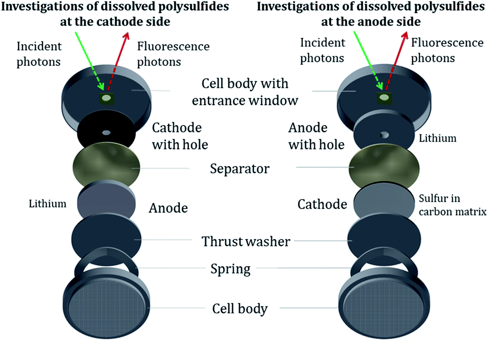 | ||
| Fig. 1 Modified CR2032 coin cells for operando NEXAFS measurements to investigate dissolved PS in the near of the cathode (left) and the anode (right). When analyzing through the aperture, the signal from cathodic S is avoided and only PS dissolved in the electrolyte are detected, which is essential for quantitative analysis. | ||
 | ||
| Fig. 2 Extended schematic side view of the operando cells to depict the probing volume for NEXAFS measurements. (1) Stainless steel coin cell body (commercial CR2032 type) with a hole of 2 mm diameter (2) window consisting of 4 μm HOPG material manually glued in the cell body enables high transmittance as well as working in UHV environment, (3) positive electrode composed of 15 μm aluminum foil as a current collector and 50 μm active material (sulfur, carbon black, binder) with a probing hole (4) hole in the investigated electrode with a diameter of 3 mm and filled with electrolyte, (5) probing volume for detecting the PS depending on the beam dimensions and the electrolyte components. (6) Incident photons, (7) fluorescence photos, (8) separators consisting of 125 μm Freudenberg FS2190 separator facing the cathode side and a 25 μm Celgard 2325 separator facing the anode side. (9) Anode of 500 μm metallic lithium. | ||
In contrast to the works by Cuisinier et al.,14 Gorlin et al.15 and Dominko et al.,21 who used non-sulfurous salts, we employed the standard and most promising salt for Li/S batteries, lithium bis(trifluoromethanesulfonyl)imide (LiTFSI), as conductive salt in 1,3-dioxolane and 1,2-dimethoxyethane (DOL/DME). This chemical composition of the electrolyte yields additional resonances of oxidized sulfur in the XAFS spectra, which is addressed by a more complex data processing. In addition, our experimental approach enables direct access not only to the PS formation but also to transport process from two different locations inside the cell. While most previous studies concentrate on the initial formation of PS, we investigated the formation as well as the evolution over the first three charge–discharge cycles for both electrodes, which is important to study the PS shuttle effect.
The probing volume for detecting the PS depends on the beam dimensions and the electrolyte components. For the used electrolyte as described above, the penetration depth for photons with energies around 2.74 keV is up to 30 μm. The beam dimensions are 300 μm × 325 μm for an incident angle φ of 22.5°. An extended schematic side view of the measurement geometry is shown in Fig. 2.
The NEXAFS experiments were carried out at the four-crystal monochromator (FCM) beamline32 in the laboratory of the Physikalisch-Technische Bundesanstalt (PTB)25 at the synchrotron radiation facility BESSY II in Berlin. All measurements were performed in an ultra-high vacuum (UHV) chamber23 at a pressure of around 2 × 10⁻⁷ mbar due to the tender X-rays used. The operando cells are measured directly after assembling to keep calendar aging and self-discharge effects as low as possible. Considering the transfer to UHV and adjusting the cell position for the NEXAFS measurements, the waiting time before the actual experiment was less than 4 hours. All NEXAFS measurements are performed in fluorescence mode. A calibrated energy-dispersive silicon drift detector (SDD) counted the emitted fluorescence photons,33 and a calibrated photodiode recorded the incident photon flux, serving as a calibration reference for the NEXAFS investigations.
3 Results and discussion
We investigated the electrochemical cycling performance of the operando cells with a galvanostatic charge/discharge, with X-ray radiography (Fig. S2†) and with cyclic voltammetry (Fig. S1†) to evaluate any possible influence of the holes in the electrodes on the cell performance. The results are shown in detail in the ESI.† Compared with cells with non-modified electrodes, the operando cell performance does not suffer from the hole.NEXAFS spectra from studies investigated directly the cathode suffer under self-absorption effects due to high cathodic sulfur content, so that quantitative operando analysis is not appropriate. Performing sulfur K-edge NEXAFS with our operando cells shown in Fig. 1, the spectra only contain contributions from the sulfur in dissolved PS as well as sulfur from the electrolyte salt. In that case of low self-absorption, a NEXAFS spectrum can be considered as the weighted sum of the individual components. Reference spectra for dissolved PS and the conductive salt are shown separately in Fig. S4.†
Each operando NEXAFS measurement takes around 12 minutes while the cell is continuously cycled at 0.1C discharge current and 0.2C charge current between potential limits of 1.6 V and 2.8 V for the first three cycles. In total, about 85 single NEXAFS spectra were recorded over a period of 20 hours for each electrode side. The spectra shown in Fig. 3 are normalized to the incident radiant power, SDD efficiency, and the solid angle of detection.
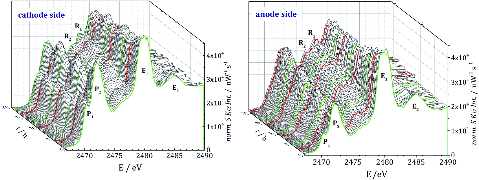 | ||
| Fig. 3 Sulfur K-edge NEXAFS measurements for the first three discharge/charge cycles at the cathode (left) and anode side (right). The green curves are the NEXAFS measurements at the beginning of the discharge. The red curves represent the NEXAFS scans when the cell passes the fully discharged state. | ||
Both cells contain resonances P1 and P2 from PS and E1 and E2 from the conductive salt LiTFSI. The main signal E1 at 2480 eV originates from the sulfonyl group of LiTFSI in the electrolyte salt. For all the PS, a white line (primary signal P2) in the energy range around 2472.1 eV and a pre-edge at 2470.2 eV (P1) are detected. While the white line represents S–S bonds, the pre-edge signal originates from the Li–S metal bonds.2 Even before the beginning of cycling, the presence of PS, caused by the self-discharge mechanism,13 is clearly visible. For the anode side and especially for subsequent cycles, the spectra are noisier than for the cathode side. The lithiation and delithiation could lead to an effective decrease of the anodes' hole diameter, which causes scattering effects due to the light lithium atoms and with that more noise in the spectra.
During cycling, two additional resonances R1 and R2 at 2476.2 eV and 2477.7 eV are detected. We assign them to side reactions, electrolyte decomposition and radiation damage, where functional groups with different S species can be formed.
Furthermore, the radical S3−, which would show a resonance at 2468.5 eV, was not observed on the cathode nor on the anode side. This is in agreement with the NEXAFS studies of Cuisinier et al.34 but in contrast to the work of Wang et al.,35 where the radical for this type of electrolyte was detected with electron paramagnetic resonance (EPR) analysis. This may indicate that the radical could only occur inside the cathode or directly at the cathode surface.
3.1 Quantification
The peak areas of the resonances P1 and P2 are proportional to the amount of sulfur in dissolved PS. Therefore, a spectral deconvolution of each NEXAFS spectrum is performed by using Voigt functions for the resonances and a step function for the K-absorption edge.For a reference-free quantification of the PS mass deposition we use the detected fluorescence signal at an incident photon energy of 2475 eV, since there is nearly no fine structure from PS and the contribution from S in the electrolyte or decomposed electrolyte (resonances R1 and R2 in Fig. 3) is low. The partial photo ionization cross-section36 for the S–K edge at 2475 eV, as well as the fluorescence yield and the relevant mass attenuation coefficients, are taken from the X-raylib37 database. Further details, including the Sherman equation used for quantification, can be found in the ESI.†
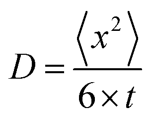
The formation of PS takes place at the surface of the positive electrode, but the detection volume is in the middle of the electrode hole (see Fig. 2). The movement of dissolved PS is a 3-dimensional Brownian movement, and the diffusion coefficient is
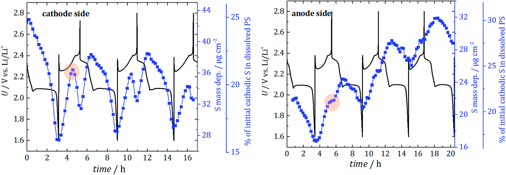 | ||
| Fig. 4 Direct comparison of the absolute mass deposition (blue curve) of S in dissolved PS for the cathode side (left) and anode side (right) for the first three full cycles. The electrochemical performance is shown in black. To compare the cells with different amounts of initial sulfur loading, the percentage of lost cathodic sulfur is determined (3rd y-axis). For the anode side, PS quantification starts after one hour of discharge at first due to beam instabilities. Highlighted is the turning point at 2.35 V in the recharge process that results in a PS concentration gradient. | ||
Additionally, and in conjunction with an estimation of the information depth from which the detected S fluorescence originates, the quantified PS mass deposition can be converted into an absolute mass of PS inside a given volume of electrolyte. To estimate the percentage of initial cathodic sulfur converted in dissolved PS, the inhomogeneities of the different PS in the electrolyte are disregarded in the first approximation. With the known initial cathodic S loadings (determined by weighing) of 2.9 mg for the cell with a hole in the cathode and 1.75 mg for the cell with a hole in the anode, this yields that about 25% and 21% of the cathodic S is dissolved as PS even before starting the cycling of the cells used in the experiment. That corresponds to a concentration of 0.44 mol l−1. The different S mass loadings for the two cells originate from the manual fabrication with knife-edge technique. Performance variations caused by different amounts of cathodic sulfur could be prevented by using mechanized process technology to generate electrodes with optimized reproducibility of S content. In contrast to the mass deposition, the determined fraction of lost cathodic sulfur (displayed as the third y-axis in Fig. 4) has to be seen only as a rough estimation because of the aforementioned approximations.
The two cells are shown here to have a nominal specific discharge capacity of 530 mA h g−1 and 570 mA h g−1 (hole in the cathode and hole in the anode) for the first cycle. Although the initial capacities are not pretty high, the capacity was stable over the three investigation cycles, indicating a well-working battery system with minor fading. CV and X-ray radiography measurements support this finding, see ESI† (“validation of the cell concept”). While, for the anode side, a steady increase of the average PS signal with cyclic fluctuations is detected, the amount at the cathode side is only slightly increased after the first three cycles. In consequence, there is a gradient between the electrodes after three cycles and more PS diffuse towards the anode side.
For the first discharge, at both cell sides, the dissolved PS mass deposition decreases until the cell is fully discharged. In this phase, the formation of insoluble Li2S starts inside the cathode or at the anode surface. Note that the electrode surface itself is not probed due to the hole in the electrodes. The minima of the dissolved PS mass deposition occur when the cells are fully discharged as expected.
During the first recharge, a strong increase in the amount of S in PS is visible for both electrode sides. After approximately half the recharge, a turning point at 2.35 V is reached for the cathode side, and the PS intensity starts to decrease. A local minimum is reached, when the cell is fully recharged according to the formed cathodic S. In contrast to that, for the recharge at the anode side, just a reduction of the slope is detected. That can be explained by a significant movement of PS from the cathode to the anode side during the recharge process due to a sudden increase in concentration gradient between both electrode compartments. During the charging process in Li/S system, lithium ions move from the positive to the negative electrode, which hampers the movement of polysulfides from the anode to the cathode (because it is the opposite direction) and thus leads to an accumulation at the anode side. Due to the lithium metal electrode's potential during charge, there is no electrochemical oxidation in the electrolyte near the anode possible. However, at the same time, the oxidation of polysulfides occurs at the cathode. This creates a concentration gradient and leads to the diffusion of only a fraction of PS back into the electrolyte near the cathode. Hence, the actual formation of the PS is not the main problem, but the concentration driven PS movement to the anode side, which happens during that described recharge process, which is detected for all three cycles.
For the second discharge, there is an increase until the second discharge plateau at 2.1 V is reached. This means that, until 2.1 V, elemental S reacts to form soluble PS, and, at the second plateau, the formation of insoluble Li2S starts and leads to the decrease of dissolved PS. This is in agreement with observations in ref. 8 and 30.
The increase over time indicates that more and more dissolved PS are present in the electrolyte at the anode side, which do not diffuse back to the cathode and form S and, consequently, an increasing amount of cathodic active material is lost.
3.2 Average polysulfide length
In addition to the quantitative information presented, the evolution of the ratio of the two PS resonances (P1 and P2 in Fig. 3) provides information about the average PS chain length. Since long-chained PS have more S–S bonds than short-chained ones, the ratio of Li–S (resonance P1) to S–S (resonance P2) signals indicates the average PS length. In Fig. 5, the P1/P2 intensity ratio is plotted as a function of the cycling time together with the electrochemical behavior.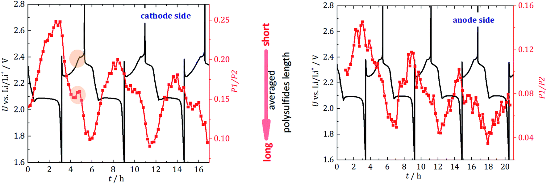 | ||
| Fig. 5 Ratio of P1/P2 (red) to gain information about the average PS chain lengths for the cathode side (left) and for the anode side (right). The black curve indicates the electrochemical behavior. Highlighted is the turning point, where longer PS react to shorter PS and elemental S. | ||
For the cathode side, a linear decrease of the average chain length is detected during discharge until approximately half of the second discharge plateau is reached, at which point the rate decreases. The PS are the shortest right before the cell is fully discharged, which agrees well with expectations and theory.30 When the cell is recharged, the chain length constantly increases until halfway into recharge, where a dip to shorter PS is observed. This dip correlates with the voltage change during recharge and cannot be clearly observed on the anode side. It may be caused by the onset of the sulfur crystal nucleation and growth process. Longer PS disproportionate into short-chain PS and precipitated S8 (e.g., 2Li2S8 → 2Li2S4 + S8). The phase transition (PS to S8) would be in agreement with the dip in the galvanostatic cycling curve. Operando X-ray radiography studies show the precipitation of β-sulfur crystals at this state of charge.40 Also, operando XRD studies found the formation of crystalline sulfur at this characteristic point of the voltage curve.41,42 The gradual increase in long-chain PS at the anode side substantiates the fading mechanism discussed above. The sudden formation of long-chain PS at the cathode side during charge and the accompanying concentration driven migration of these PS through the separator leads to a stepwise accumulation of long-chain PS at the anode side. Unfortunately, these PS are the most vulnerable species towards unwanted side reactions with the metallic lithium anode.
Additionally, it could be explained that during recharge, longer PS, which are the best soluble in the electrolyte, travel to the anode side and cause an effective shorter chain length at the cathode side. This agrees with the observation that this local maximum is not seen on the anode side, where a constant reaction to longer chains is detected. Both processes can lead to the effective accumulation of PS on the anode side which has been observed (Fig. 4).
Furthermore, we performed Raman analysis43 (vibrational spectroscopy) to identify the different PS species on the anode side through their fingerprint spectrum (see ESI Fig. S4 and S5†) to validate our NEXAFS results. Raman spectroscopy allows for the identification of chemical species by their vibration spectrum and is particularly suitable for non-polar, covalent molecules. Because of these characteristics, the Raman method is also well suited for operando investigations of Li/S cells.43–47 Our presented operando cell is suitable for Raman spectroscopy just by substituting the window material (Kapton instead of HOPG). Although the techniques have different penetration depth, after PS formation during first discharge, similar periodic behavior for PS in NEXAFS and Raman measurements is detected. The advantage of vibrational spectroscopy is the access to the individual PS. We detected, that after formation during the first discharge, Li2S4 is the main PS for the first three cycles.
4 Conclusion
With our cell design for dissolved PS and operando sulfur NEXAFS, we have gained for the first time a direct and operando comparison of the absolute amount of dissolved PS with the electrochemical performance of the cell. We proved that the amount of dissolved PS is related to the cells' capacity. We observed initial cathodic S present in dissolved polysulfides of 21% and 25% for the two operando cells. Our studies are in agreement with the results of Diao et al.48 who used ex situ Inductively Coupled Plasma-Optical Emission Spectrometry (ICP-OES) to determine S in dissolved PS. They observed a 20% cathodic sulfur loss for the discharged state, which is the same magnitude that our results have shown. For the charged state, they detected 45% of dissolved S which is much larger than our results which may be explained by their electrode washing and dilution processes. Our approach using calibrated instrumentation and fundamental parameter leads to a quantification with no need for a calibration sample with known concentrations.With the investigation over the first three full cycles in combination with the high time resolution of only 12 min per NEXAFS and spatial resolution, we got access to the different behavior of PS for the cathode and the anode side. While PS are formed with the start of the discharging process of the cell (or even earlier due to self-discharging), we conclude that the main issue for an increasing PS concentration in the electrolyte is the recharging process at 2.35 V. We clearly observed that PS do not diffuse back completely to the cathode side, so that their amount at the anode side increases steadily. With investigations of the average PS chain length the reasons for this behavior can be seen either as a reaction of longer PS with Li2S to shorter PS and elemental S or the different dissolving properties for the various PS. In addition, the diffusion of polysulfides from the anode to the cathode side during charge is hampered caused by the lithium current in the opposite direction. To address this problem and to improve Li/S batteries, the application of a retarding agent or a sparingly solvating solvent could decrease this effect.
Further, we would like to emphasize that the presented quantitative NEXAFS based technique for operando characterization of processes in batteries does not require major changes to the battery structure but can be performed on realistic coin cell batteries. In addition, the used operando techniques enable the investigation of separator materials regarding PS retention. In perspective, the presented methodology can be readily applied to other types of battery materials, e.g., LIBs. It can thus serve as a novel toolset for advanced operando correlation and degradation studies over multiple charging cycles to provide insights for a deeper understanding of mechanisms in current and future battery materials.
Conflicts of interest
There are no conflicts to declare.Acknowledgements
We would like to thank Nikolay Kardjilov and Ingo Manke from Helmholtz-Zentrum Berlin for performing the X-ray Radiography measurements of our cell. We would also like to thank Dr Dieter Fischer and Julia Muche at Leibniz Institut für Polymerforschung Dresden for the ample help and support during the Raman experiments. This research was funded by the German Science Foundation (DFG Project ISIBAT Sta 324/54).References
- X. Ji and L. F. Nazar, Advances in Li–S batteries, J. Mater. Chem., 2010, 20, 9821, 10.1039/b925751a.
- R. Dominko, A. Vizintin, G. Aquilanti, L. Stievano, M. J. Helen, A. R. Munnangi, M. Fichtner and I. Arcon, Polysulfides Formation in Different Electrolytes from the Perspective of X-ray Absorption Spectroscopy, J. Electrochem. Soc., 2018, 165, A5014–A5019, DOI:10.1149/2.0151801jes.
- Q. He, A. T. S. Freiberg, M. U. M. Patel, S. Qian and H. A. Gasteiger, Operando Identification of Liquid Intermediates in Lithium–Sulfur Batteries via Transmission UV-vis Spectroscopy, J. Electrochem. Soc., 2020, 167, 80508, DOI:10.1149/1945-7111/ab8645.
- J. Hannauer, J. Scheers, J. Fullenwarth, B. Fraisse, L. Stievano and P. Johansson, The Quest for Polysulfides in Lithium–Sulfur Battery Electrolytes: An Operando Confocal Raman Spectroscopy Study, ChemPhysChem, 2015, 16, 2755–2759, DOI:10.1002/cphc.201500448.
- N. Saqib, C. J. Silva, C. Mark Maupin and J. M. Porter, A Novel Optical Diagnostic for In Situ Measurements of Lithium Polysulfides in Battery Electrolytes, Appl. Spectrosc., 2017, 71, 1593–1599 CrossRef CAS PubMed.
- C. Dillard, A. Singh and V. Kalra, Polysulfide Speciation and Electrolyte Interactions in Lithium–Sulfur Batteries with in situ Infrared Spectroelectrochemistry, J. Phys. Chem. C, 2018, 122, 18195–18203, DOI:10.1021/acs.jpcc.8b02506.
- G. Aquilanti, M. Giorgetti, R. Dominko, L. Stievano, I. Arčon, N. Novello and L. Olivi, Operando characterization of batteries using X-ray absorption spectroscopy: advances at the beamline XAFS at synchrotron Elettra, J. Phys. D: Appl. Phys., 2017, 50, 74001, DOI:10.1088/1361-6463/aa519a.
- J. Conder, R. Bouchet, S. Trabesinger, C. Marino, L. Gubler and C. Villevieille, Direct observation of lithium polysulfides in lithium–sulfur batteries using operando X-ray diffraction, Nat. Energy, 2017, 2, 17069, DOI:10.1038/nenergy.2017.69.
- H. Wang, Y. Yang, Y. Liang, J. T. Robinson, Y. Li, A. Jackson, Y. Cui and H. Dai, Graphene-wrapped sulfur particles as a rechargeable lithium–sulfur battery cathode material with high capacity and cycling stability, Nano Lett., 2011, 11, 2644–2647, DOI:10.1021/nl200658a.
- M. Agrawal, S. Choudhury, K. Gruber, F. Simon, D. Fischer, V. Albrecht, M. Göbel, S. Koller, M. Stamm and L. Ionov, Porous carbon materials for Li–S batteries based on resorcinol–formaldehyde resin with inverse opal structure, J. Power Sources, 2014, 261, 363–370, DOI:10.1016/j.jpowsour.2014.03.052.
- Y. Yang, M. T. McDowell, A. Jackson, J. J. Cha, S. S. Hong and Y. Cui, New Nanostructured Li2S/Silicon Rechargeable Battery with High Specific Energy, Nano Lett., 2010, 10, 1486–1491, DOI:10.1021/nl100504q.
- M. A. Lowe, J. Gao and H. D. Abruña, Mechanistic insights into operational lithium–sulfur batteries by in situ X-ray diffraction and absorption spectroscopy, RSC Adv., 2014, 4, 18347, 10.1039/c4ra01388c.
- J. Gao, M. A. Lowe, Y. Kiya and H. D. Abruña, Effects of Liquid Electrolytes on the Charge–Discharge Performance of Rechargeable Lithium/Sulfur Batteries: Electrochemical and in situ X-ray Absorption Spectroscopic Studies, J. Phys. Chem. C, 2011, 115, 25132–25137, DOI:10.1021/jp207714c.
- M. Cuisinier, P.-E. Cabelguen, S. Evers, G. He, M. Kolbeck, A. Garsuch, T. Bolin, M. Balasubramanian and L. F. Nazar, Sulfur Speciation in Li–S Batteries Determined by Operando X-ray Absorption Spectroscopy, J. Phys. Chem. Lett., 2013, 4, 3227–3232, DOI:10.1021/jz401763d.
- Y. Gorlin, A. Siebel, M. Piana, T. Huthwelker, H. Jha, G. Monsch, F. Kraus, H. A. Gasteiger and M. Tromp, Operando Characterization of Intermediates Produced in a Lithium–Sulfur Battery, J. Electrochem. Soc., 2015, 162, A1146–A1155, DOI:10.1149/2.0081507jes.
- M. Müller, S. Choudhury, K. Gruber, V. B. Cruz, B. Fuchsbichler, T. Jacob, S. Koller, M. Stamm, L. Ionov and B. Beckhoff, Sulfur X-ray absorption fine structure in porous Li–S cathode films measured under argon atmospheric conditions, Spectrochim. Acta, Part B, 2014, 94–95, 22–26, DOI:10.1016/j.sab.2014.03.001.
- Y. Gorlin, M. U. M. Patel, A. Freiberg, Q. He, M. Piana, M. Tromp and H. A. Gasteiger, Understanding the Charging Mechanism of Lithium–Sulfur Batteries Using Spatially Resolved Operando X-Ray Absorption Spectroscopy, J. Electrochem. Soc., 2016, 163, A930–A939, DOI:10.1149/2.0631606jes.
- K. H. Wujcik, D. R. Wang, T. A. Pascal, D. Prendergast and N. P. Balsara, In Situ X-ray Absorption Spectroscopy Studies of Discharge Reactions in a Thick Cathode of a Lithium–Sulfur Battery, J. Electrochem. Soc., 2017, 164, A18–A27, DOI:10.1149/2.1441614jes.
- A. T. S. Freiberg, A. Siebel, A. Berger, S. M. Webb, Y. Gorlin, M. Tromp and H. A. Gasteiger, Insights into the Interconnection of the Electrodes and Electrolyte Species in Lithium–Sulfur Batteries Using Spatially Resolved Operando X-ray Absorption Spectroscopy and X-ray Fluorescence Mapping, J. Phys. Chem. C, 2018, 122, 5303–5316, DOI:10.1021/acs.jpcc.7b12799.
- Y. Ye, A. Kawase, M.-K. Song, B. Feng, Y.-S. Liu, M. A. Marcus, J. Feng, E. J. Cairns, J. Guo and J. Zhu, X-ray Absorption Spectroscopy Characterization of a Li/S Cell, Nanomaterials, 2016, 6 DOI:10.3390/nano6010014.
- R. Dominko, M. U. M. Patel, V. Lapornik, A. Vizintin, M. Koželj, N. N. Tušar, I. Arčon, L. Stievano and G. Aquilanti, Analytical Detection of Polysulfides in the Presence of Adsorption Additives by Operando X-ray Absorption Spectroscopy, J. Phys. Chem. C, 2015, 119, 19001–19010, DOI:10.1021/acs.jpcc.5b05609.
- L. Zhang, D. Sun, J. Feng, E. J. Cairns and J. Guo, Revealing the Electrochemical Charging Mechanism of Nanosized Li2S by in situ and Operando X-ray Absorption Spectroscopy, Nano Lett., 2017, 17, 5084–5091, DOI:10.1021/acs.nanolett.7b02381.
- J. Lubeck, B. Beckhoff, R. Fliegauf, I. Holfelder, P. Hönicke, M. Müller, B. Pollakowski, F. Reinhardt and J. Weser, A Novel Instrument for Quantitative Nanoanalytics Involving Complementary X-Ray Methodologies, Rev. Sci. Instrum., 2013, 84, 45106, DOI:10.1063/1.4798299.
- B. Beckhoff, Reference-Free X-Ray Spectrometry Based on Metrology Using Synchrotron Radiation, J. Anal. At. Spectrom., 2008, 23, 845, 10.1039/b718355k.
- B. Beckhoff, A. Gottwald, R. Klein, M. Krumrey, R. Müller, M. Richter, F. Scholze, R. Thornagel and G. Ulm, A Quarter-Century of Metrology Using Synchrotron Radiation by PTB in Berlin, Phys. Status Solidi B, 2009, 246, 1415–1434, DOI:10.1002/pssb.200945162.
- M. Kolbe and P. Hönicke, Fundamental parameters of Zr and Ti for a reliable quantitative X-ray fluorescence analysis, X-Ray Spectrom., 2015, 44, 217–220, DOI:10.1002/xrs.2603.
- L. Zielke, C. Barchasz, S. Waluś, F. Alloin, J.-C. Leprêtre, A. Spettl, V. Schmidt, A. Hilger, I. Manke, J. Banhart, R. Zengerle and S. Thiele, Degradation of Li/S Battery Electrodes On 3D Current Collectors Studied Using X-ray Phase Contrast Tomography, Sci. Rep., 2015, 5, 359, DOI:10.1038/srep10921.
- X. Feng, M.-K. Song, W. C. Stolte, D. Gardenghi, D. Zhang, X. Sun, J. Zhu, E. J. Cairns and J. Guo, Understanding the degradation mechanism of rechargeable lithium/sulfur cells: a comprehensive study of the sulfur–graphene oxide cathode after discharge–charge cycling, Phys. Chem. Chem. Phys., 2014, 16, 16931–16940, 10.1039/C4CP01341G.
- J. Tan, D. Liu, X. Xu and L. Mai, In situ/operando characterization techniques for rechargeable lithium–sulfur batteries: a review, Nanoscale, 2017, 9, 19001–19016, 10.1039/c7nr06819k.
- S. S. Zhang, Liquid electrolyte lithium/sulfur battery: fundamental chemistry, problems, and solutions, J. Power Sources, 2013, 231, 153–162, DOI:10.1016/j.jpowsour.2012.12.102.
- Q. Pang, D. Kundu, M. Cuisinier and L. F. Nazar, Surface-enhanced redox chemistry of polysulphides on a metallic and polar host for lithium–sulphur batteries, Nat. Commun., 2014, 5, 4759, DOI:10.1038/ncomms5759.
- M. Krumrey, Design of a Four-Crystal Monochromator Beamline for Radiometry at BESSY II, J. Synchrotron Radiat., 1998, 5, 6–9, DOI:10.1107/S0909049597011825.
- F. Scholze and M. Procop, Measurement of detection efficiency and response functions for an Si(Li) X-ray spectrometer in the range 0.1–5 keV, X-Ray Spectrom., 2001, 30, 69–76, DOI:10.1002/xrs.472.
- M. Cuisinier, C. Hart, M. Balasubramanian, A. Garsuch and L. F. Nazar, Radical or Not Radical: Revisiting Lithium–Sulfur Electrochemistry in Nonaqueous Electrolytes, Adv. Energy Mater., 2015, 5, 1401801, DOI:10.1002/aenm.201401801.
- Q. Wang, J. Zheng, E. Walter, H. Pan, D. Lv, P. Zuo, H. Chen, Z. D. Deng, B. Y. Liaw, X. Yu, X. Yang, J.-G. Zhang, J. Liu and J. Xiao, Direct Observation of Sulfur Radicals as Reaction Media in Lithium Sulfur Batteries, J. Electrochem. Soc., 2014, 162, A474–A478, DOI:10.1149/2.0851503jes.
- P. Hönicke, M. Kolbe and B. Beckhoff, What are the correct L-subshell photoionization cross sections for quantitative X-ray spectroscopy?, X-Ray Spectrom., 2016, 45, 207–211, DOI:10.1002/xrs.2691.
- T. Schoonjans, A. Brunetti, B. Golosio, M. Sanchez del Rio, V. A. Solé, C. Ferrero and L. Vincze, The X-raylib library for X-ray–matter interactions. Recent developments, Spectrochim. Acta, Part B, 2011, 66, 776–784, DOI:10.1016/j.sab.2011.09.011.
- C. Park, A. Ronneburg, S. Risse, M. Ballauff, M. Kanduč and J. Dzubiella, Structural and Transport Properties of Li/S Battery Electrolytes: Role of the Polysulfide Species, J. Phys. Chem. C, 2019, 123, 10167–10177, DOI:10.1021/acs.jpcc.8b10175.
- M. O. Krause, C. W. Nestor Jr, C. J. Sparks Jr and E. Ricci, X-ray fluorescence cross sections for K and L x rays of the elements, 1978 Search PubMed.
- S. Risse, C. J. Jafta, Y. Yang, N. Kardjilov, A. Hilger, I. Manke and M. Ballauff, Multidimensional operando analysis of macroscopic structure evolution in lithium sulfur cells by X-ray radiography, Phys. Chem. Chem. Phys., 2016, 18, 10630–10636, 10.1039/c6cp01020b.
- S. Waluś, C. Barchasz, J.-F. Colin, J.-F. Martin, E. Elkaïm, J.-C. Leprêtre and F. Alloin, New insight into the working mechanism of lithium–sulfur batteries: in situ and operando X-ray diffraction characterization, Chem. Commun., 2013, 49, 7899, 10.1039/c3cc43766c.
- N. A. Cañas, S. Wolf, N. Wagner and K. A. Friedrich, In situ X-ray diffraction studies of lithium–sulfur batteries, J. Power Sources, 2013, 226, 313–319, DOI:10.1016/j.jpowsour.2012.10.092.
- J.-T. Yeon, J.-Y. Jang, J.-G. Han, J. Cho, K. T. Lee and N.-S. Choi, Raman Spectroscopic and X-ray Diffraction Studies of Sulfur Composite Electrodes during Discharge and Charge, J. Electrochem. Soc., 2012, 159, A1308–A1314, DOI:10.1149/2.080208jes.
- H.-L. Wu, L. A. Huff and A. A. Gewirth, In Situ Raman Spectroscopy of Sulfur Speciation in Lithium–Sulfur Batteries, ACS Appl. Mater. Interfaces, 2015, 7, 1709–1719, DOI:10.1021/am5072942.
- B. P. Vinayan, T. Diemant, X.-M. Lin, M. A. Cambaz, U. Golla-Schindler, U. Kaiser, R. Jürgen Behm and M. Fichtner, Nitrogen Rich Hierarchically Organized Porous Carbon/Sulfur Composite Cathode Electrode for High Performance Li/S Battery: A Mechanistic Investigation by Operando Spectroscopic Studies, Adv. Mater. Interfaces, 2016, 3, 1600372, DOI:10.1002/admi.201600372.
- M. Hagen, P. Schiffels, M. Hammer, S. Dörfler, J. Tübke, M. J. Hoffmann, H. Althues and S. Kaskel, In Situ Raman Investigation of Polysulfide Formation in Li–S Cells, J. Electrochem. Soc., 2013, 160, A1205–A1214, DOI:10.1149/2.045308jes.
- J. Hannauer, J. Scheers, J. Fullenwarth, B. Fraisse, L. Stievano and P. Johansson, The Quest for Polysulfides in Lithium–Sulfur Battery Electrolytes: An Operando Confocal Raman Spectroscopy Study, ChemPhysChem, 2015, 16, 2709, DOI:10.1002/cphc.201500708.
- Y. Diao, K. Xie, S. Xiong and X. Hong, Analysis of Polysulfide Dissolved in Electrolyte in Discharge–Charge Process of Li–S Battery, J. Electrochem. Soc., 2012, 159, A421–A425, DOI:10.1149/2.060204jes.
Footnote |
| † Electronic supplementary information (ESI) available. See DOI: 10.1039/d0ta12011a |
| This journal is © The Royal Society of Chemistry 2021 |