
 Open Access Article
 This Open Access Article is licensed under a
 Creative Commons Attribution 3.0 Unported Licence
Peculiar role of the electrolyte viscosity in the electrochemical capacitor performance
Przemyslaw
Galek
 ,
Adam
Slesinski
,
Krzysztof
Fic
* and
Jakub
Menzel
*
,
Adam
Slesinski
,
Krzysztof
Fic
* and
Jakub
Menzel
*
Institute of Chemistry and Technical Electrochemistry, Poznan University of Technology, Berdychowo 4, 60-965 Poznan, Poland. E-mail: jakub.menzel@put.poznan.pl; krzysztof.fic@put.poznan.pl
First published on 15th March 2021
Abstract
This paper reports on the electrochemical performance of symmetric carbon/carbon electrochemical capacitors operating in an aqueous electrolyte (1 mol L−1 Li2SO4 solution) whose viscosity is modified by various amounts of carboxymethyl cellulose additive. The literature states that increased electrolyte viscosity usually decreases the overall capacitor performance. However, it has been found that the influence of this parameter is complex and depends significantly on the carbon electrode texture/structure properties. Fortunately, the application of viscous electrolytes is found to be beneficial in terms of reduced leakage current and internal gas evolution (by approximately 50%). Furthermore, the examination of differently structured carbons showed that in materials with well-designed micro-/mesoporous interconnectivity, it is possible to retain high power and energy performance even for devices with 104-fold increased viscosity.
1. Introduction
Energy generation and consumption are currently among the most important economic and social considerations, especially in highly developed countries. The demand for energy is increasing continuously, which requires the search for new, alternative and highly efficient energy sources.1 The generated energy is also inherently associated with the necessity of storage. Energy storage devices can have the form of bulky, large, stationary units but can also be a component of small, portable devices for everyday use, such as laptops, mobile phones, and cameras.The solutions currently proposed for high-energy-storage devices such as electrochemical cells, fuel cells, and redox flow batteries suffer from limited power output, resulting mostly from sluggish redox reaction kinetics. To overcome this limitation, one can consider electrochemical capacitors (EC), which are characterized by high power performance and long lifetimes, originating from their double-layer charge storage mechanisms.2–5 One way to benefit from both types of these devices is to merge them in the form of a hybrid system to incorporate both energy and power properties. However, such an approach significantly increases the cost of the final energy storage station. The other approach is to develop capacitors with energy approaching that of batteries while maintaining fast charge/discharge kinetics. To reach this goal, much work has been devoted to the development of the two primary EC components, namely, the electrode materials and electrolytes.
In recent years, research on electrode materials has been focused on the development of new materials with high surface porosity. In particular, most of the research has been devoted to the study of porous and layered materials such as activated carbons,2,4,6,7 graphene,8 carbon nanotubes,9,10 carbon nano-onions,11,12 and recently, MXenes as electrode materials.13,14 Nevertheless, activated carbons are still most widely used in commercial devices due to their well-developed specific surfaces, reaching 2500 m2 g−1; high accessibility; and low production costs.15
Simultaneously, a considerable amount of research has focused on electrolyte development, as their properties ultimately determine the maximum operating voltage of ECs.16–19 Currently, in commercial devices, organic-based electrolytes are the most widely used. They are characterized by wide electrochemical stability up to 3 V and the ability to operate within a broad temperature range of −40 °C to 60 °C. However, their main disadvantages are high volatility and flammability, high cost, sensitivity to moisture, and low conductivity.12,13
In recent years, the increase in environmental protection awareness has forced researchers to seek new electrolyte compositions. To meet the environmental friendliness demands, two types of electrolytes are of interest: water-based formulations and ionic liquids. Due to good electrochemical properties, excellent power ratings, and low cost, interest in aqueous-based solutions is still increasing. The main disadvantage of aqueous ECs, especially those based on acidic or alkaline electrolytes, is a narrow operating voltage window limited by thermodynamic water stability (in principle, 1.23 V).20 However, the practical maximum voltage of the devices based on this type of electrolyte can be increased by adjusting the physicochemical properties. Modification of the electrolyte (pH or conductivity) and/or surface chemistry of activated carbons (AC) is a way to affect the evolution potential of di-hydrogen and/or oxidation of the electrode. It results in increased voltage.21 In some cases, it is possible to achieve a voltage of up to 1.8 V.22–24 However, the latest research on “water-in-salt” electrolytes shows that even more than 2 V can be achieved for very concentrated electrolytes.25,26
The third group of electrolytes is ionic liquids; their advantages include the possibility of reaching high voltages, up to 4 V;27–31 non-flammability; and environmental friendliness. However, their high production cost and poor conductivity limit their application ability in high-power devices.
According to many authors, the ideal electrolyte should be characterized by a wide potential window, low resistance, low viscosity, non-flammability, high electrochemical stability, and environmental friendliness.7 In the literature, one can find that high viscosity hinders the mobility of ions in a conductive medium, which is associated with low conductivity.32–37 The diffusion of ions through an electrolyte, leading to the formation of an electric double layer at the electrode/electrolyte interface, is not fast enough during repeated charging/discharging processes, which reduces the EC power and, ultimately, the efficiency. Thus, the transport properties of the electrolyte, such as low ion conductivity and high viscosity, negatively affect the device performance.38 The authors also report reduced device power and increased resistance while using such an electrolyte. Among the disadvantages, there is also poor wettability of the electrodes and poor pore penetration ability of the strongly developed electrode surface. Poor wettability reduces the effective use of the highly developed specific surface area of the carbon material. It has been shown that the low viscosity of water electrolytes enables easy diffusion of ions into pores with diameters less than 1 nm. Additionally, the presence of oxygen/nitrogen functional groups on the surface of the carbon in combination with the aqueous electrolyte increases the capacitive performance of the device by modifying the electronic structure of the carbon electrode.39
The viscosity of electrolytes of organic origin is similar to or even lower than that of aqueous electrolytes. However, their conductivity is limited, e.g., 1 mol L−1 TEA−BF4 in acetonitrile 56 mS cm−1, 1 mol L−1 LiPF6 in acetonitrile, 50 mS cm−1, 1 mol L−1 LiTFSI in acetonitrile 36 mS cm−1,40 1 mol L−1, and LiPF6 in EC![[thin space (1/6-em)]](https://www.rsc.org/images/entities/char_2009.gif) :DMC 10 mS cm−1.
:DMC 10 mS cm−1.
For some solvents, such as ethylene carbonate (EC), where the melting point is slightly above ambient temperature (35 and 38 °C), dimethyl carbonate (DMC), ethyl methyl carbonate (EMC), methyl butyrate (MB), or ethyl butyrate (EB) is added to decrease the viscosity, which simultaneously improves the melting temperature and electrolyte temperature stability. However, due to the increase in the equivalent cell series resistance (ESR), the power density deteriorates.41,42 It has been shown that the range of EC working temperatures can be expanded without sacrificing conductivity and viscosity when using the eutectic IL mixture.43,44
Self-discharge is an unavoidable problem for ECs that causes loss of voltage and stored energy.45,46 Due to self-discharge, the widespread use of electrochemical capacitors as long-term backup energy devices is severely limited. It is accepted that charged ECs are in a high energy state and that the Gibbs free energy is a driving force that induces (mostly) self-discharge. There are three main processes responsible for self-discharge: spontaneous charge diffusion and its redistribution,47–49 faradaic reactions50,51 and so-called ohmic leakage.47 Charge redistribution is caused by the movement or loss of charged ions adsorbed on the electrode due to their concentration gradient.52 Faradaic reactions concern the oxidation or reduction of redox species on the surface of the electrode. Ohmic leakage occurs due to the internal ohmic leakage pathways between electrodes. All these processes will lead to a reduction in voltage and a loss of stored energy of the charged device. Several solutions to this problem have been proposed, including the formation of an insulating layer on the electrode by depositing a thin film of poly(p-phenylene oxide).53 Another method is to use an ion-exchange membrane for active redox54 or addition of surfactants to the electrolyte.55 Due to the long alkyl chain, surfactants adsorbed on the surface of the electrode should serve as a micro-insulator and hinder the flow of discharge current. The method proposed by Xia M. et al. turned out to be a very effective solution.52 They proposed the use of increased electrolyte viscosity in the electrode vicinity. The nematic phase of the 4-N-pentyl-4′-cyanobiphenyl liquid crystal was used for this purpose as an addition to the primary electrolyte. When the EC is charged, the electric field in the double layer near the surfaces of the electrodes induces alignment of the additive particles, resulting in a significantly increased viscosity of the fluid by means of an electrorheological effect. As a result, the diffusion of ions and redox compounds in the electrolyte may be hindered; however, the rate of self-discharge may be reduced. The simulation results confirmed the reduced contribution of both ion diffusion and faradaic reaction to self-discharge. With this solution, the charge efficiency which was obtained was much higher than that of the electric double-layer capacitor (EDLC) without additive.
The authors each time stress the negative effect of increased viscosity, but the positive aspects of such electrolytes are usually neglected.
Our work aims to verify this popular approach in terms of the use of highly viscous electrolytes in electrochemical capacitors. For this purpose, the aqueous 1 mol L−1 Li2SO4 electrolyte was modified by the addition of the carboxymethyl cellulose (CMC) additive, which allows strict control of the solution viscosity. The obtained result provides new insights into the problem of electrolyte viscosity and shows that viscosity itself is not the limiting parameter.
2. Experimental section
2.1 Electrolytes
An aqueous solution of 1 mol L−1 Li2SO4 was prepared by dissolving the appropriate mass of Li2SO4 salt (purity – 99%, Sigma-Aldrich®) in deionized water. Sodium carboxymethylcellulose (CMC) (substitution degree, 1.2; Sigma-Aldrich®) and guar gum (GG) (Sigma-Aldrich®) were selected as viscosity-adjusting agents. The modified electrolytes were prepared by dissolving the relevant mass of CMC (1, 3, 5, and 7 wt%) and GG (1, 2, 3 wt%) in 1 mol L−1 Li2SO4 prepared before. The additives were intended to increase the viscosity only, not to become a source of additional redox activity in the system. Conductivity measurements were performed using a conductometer (Mettler Toledo®), and the final conductivity was the average of three measurements. The viscosity of the electrolytes was examined by a Brookfield® DV2T viscometer.2.2 Electrodes
Carbon electrodes were prepared by the wet method. Three types of carbon materials were used in the research as electrode materials: pristine mesoporous Norit® SX2 (SX2n-A) (897 m2 g−1), microporous AC Kuraray® YP-80F (YP-80F) (1717 m2 g−1) and KOH-activated Norit® SX2 (SX2A) (1833 m2 g−1). The electrodes were prepared by 24 h of mechanical mixing of the AC powders with a 60% polytetrafluoroethylene (PTFE) solution in a ratio of 95:5 (AC:PTFE) immersed in isopropanol until homogeneity was achieved. The homogenized material was formed into rectangular sheets, calendered to produce a 200 μm thick film and dried for 12 h at 70 °C. The specific surface area, pore volume and pore distribution of individual carbonaceous materials were determined by nitrogen adsorption at 77 K with an ASAP 2460 sorptiometer (Micromeritics®, USA). For comparative purposes, the physio-chemical properties of microporous YP-50F were measured and are presented.
2.3 Electrochemical investigation
Electrochemical measurements were performed in a symmetric, two-electrode Swagelok® cell and verified in a three-electrode setup. Two types of three-electrode cells were used: an SVC-3 Biologic® volume cell with two glassy carbon electrodes serving as the working and counter electrodes and a custom-made three-electrode cell with a platinum mesh serving as the counter electrode. In both cases, the Hg/Hg2SO4 reference electrode was used to monitor the potential of the electrodes. The electrodes were immersed in electrolyte for 1 h prior to the measurement and separated by a Whatman GF/A porous membrane. Long-term cycling tests were performed with application of galvanostatic charge/discharge technique at current density of 1 A g−1 for 10000 cycles. The 12-hour self-discharge measurement was performed after system has been charged to the voltages of 1 V, 1.2 V, 1.4 V and 1.6 V, followed by the voltage hold for 2 hours. All current and capacitance values are expressed per mass of one electrode. All measurements were conducted with a computer-controlled multichannel potentiostat/galvanostat (VMP3, Biologic®, France).
2.4 Internal pressure measurements
The gas generation rate was measured for a symmetric carbon/carbon system in a customized cell connected to the pressure sensor (Keller®, Switzerland). To maintain controlled conditions, the cell was placed in a thermostatic chamber at 30 °C and stabilized for 6 h before the experiment. The internal pressure build-up was measured during 2 h of constant voltage at cell voltages of 1.0 V, 1.2 V, 1.4 V, 1.6 V, and 1.8 V.2.5 Electrowetting/contact angle
The electrowetting measurements were performed with a computer-controlled goniometer (Dataphysics® OCA). The carbon samples in the form of pellets (diameter 10 mm) serving as working electrodes were placed horizontally in front of the contact angle camera and the platinum wire (counter electrode). The circuit between the electrodes was closed by placing a 3 μL electrolyte drop on the surface of the electrode material. During the measurement, the subsequent electrodes were then polarized for 6 minutes at a constant voltage. The electrochemical characteristics were carried out with a computer-controlled potentiostat/galvanostat SP-200 Biologic®, France.3. Results and discussion
Fig. 1 presents the nitrogen adsorption isotherms and pore size distributions of selected carbon materials: pristine SX2n-A, SX2A, and YP-80F.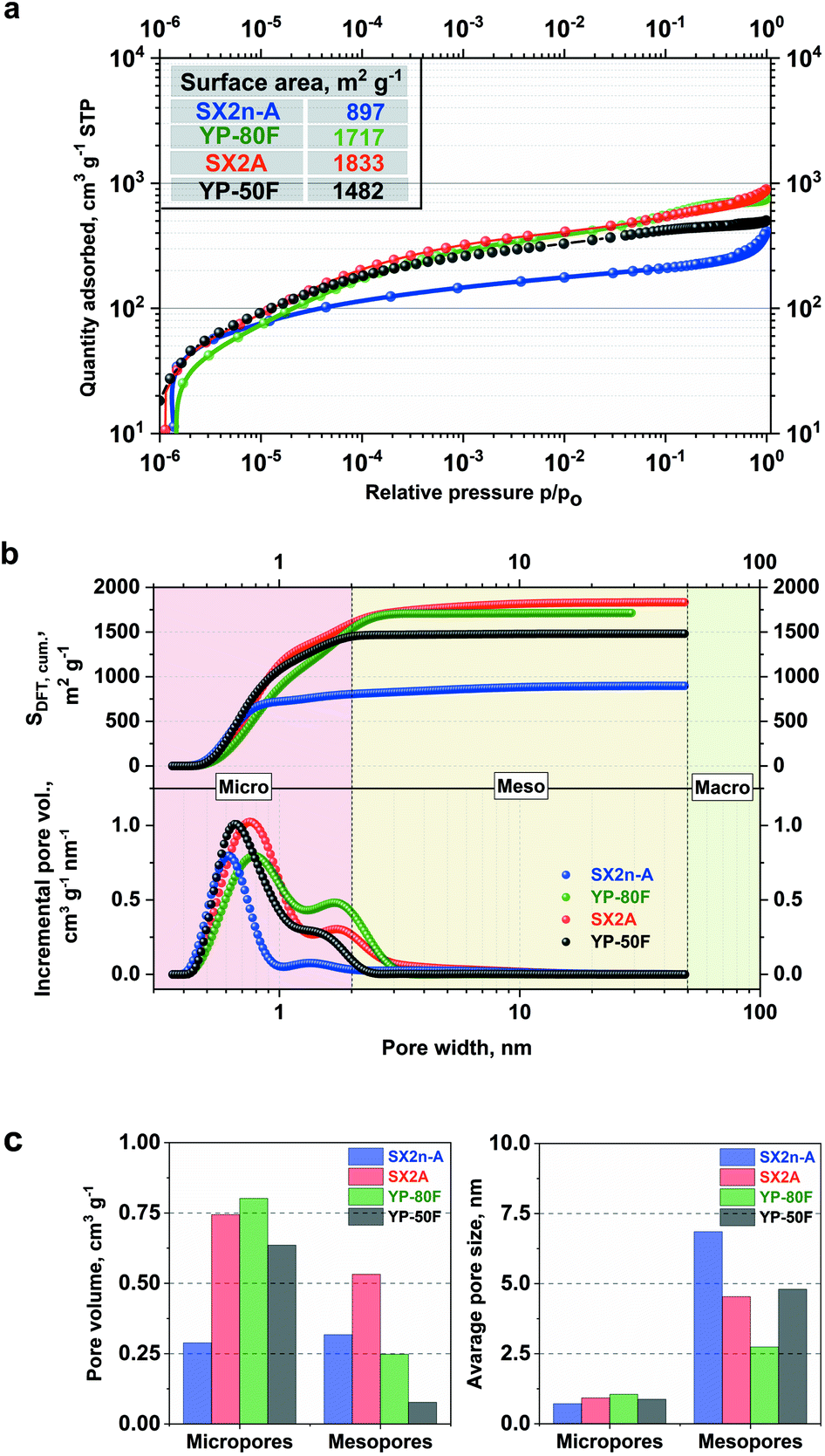 | ||
| Fig. 1 (a) Nitrogen adsorption/desorption isotherms at 77 K; (b) cumulative surface area calculated with NL-DFT method and corresponding pore size distributions; (c) pore volume and average pore size ratio of micro- to mesoporosity for selected carbon materials. | ||
All of the examined materials are represented by type I adsorption/desorption isotherms, which are characteristic of microporous AC. However, for the SX2n-A and SX2A materials, a clearly defined hysteresis loop characteristic for mesoporous materials as well as an upward trend of adsorption is observed. This might be explained by condensation of desorbed nitrogen in the bulk of the mesopores. The shapes of both isotherms are very similar; the only change is in the absolute nitrogen adsorption volume, which is the result of a higher specific surface area, i.e., 1833 m2 g−1 in the case of SX2A and 897 m2 g−1 for SX2n-A. The YP-80F and YP-50F isotherm are typical of microporous materials with an insignificant adsorption/desorption hysteresis loop, and less pronounced upward trend at higher relative pressures. These materials display a high specific surface area of 1717 m2 g−1 and 1482 m2, respectively. The comparison of cumulative surface area and pore size distribution in Fig. 1b also confirm the different porous character of selected carbons. One may observe that for all materials the highest contribution to the total surface area comes from micropores (<2 nm). Quick stabilization of the curve, thus, no further surface increase is observed for microporous carbons YP-80F and YP-50F even up to 3 nm pore width. In the case of micro–mesoporous carbons, an additional increase of the surface area is observed across the whole mesopores (2–50 nm) region. As shown by other authors, the difference in pore distribution has a significant impact on the mass transfer inside the electrode and final electrochemical capacitor performance.56 Hence, in this work, the importance of internal mesoporous channels on the performance of electrochemical capacitors in terms of viscous electrolytes will be discussed. The presented PSD plots confirm the microporous character of selected AC; moreover, the micropore/mesopore volume ratio shows that SX2A and YP-80F and especially YP-50F carbons are mostly microporous carbons. However, in SX2n-A, most of the volume is the contribution of the mesopores. Nonetheless, the comparison of average pore size shows that the SX2n-A carbon is characterized by the smallest micropores size (0.7 nm) while in the case of other carbons it is ∼1 nm. The YP-50F was used only as a comparison material to expose the differences between microporous and micro–mesoporous materials. In further work, we focus on the comparison between YP-80F and SX2A, because of similar surface area (considering both BET and DFT calculations).
To confirm the negligible impact of viscosity on the conductivity of electrolytes, two gelling agents were used, CMC and guar gum. The maximum polymer content in the electrolyte was limited by the polymer solubility. The conductivity to viscosity relation of the prepared electrolytes is presented in Fig. 2.
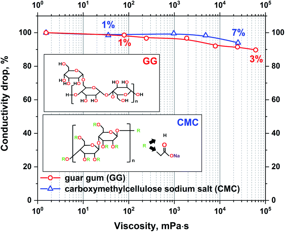 | ||
| Fig. 2 The absolute change in conductivity with increasing viscosity of the 1 mol L−1 Li2SO4 electrolyte with guar gum and CMC additives. | ||
It can be observed that even a small amount of gelling agents has a significant influence on the electrolyte viscosity. The addition of 7% CMC or 3% guar gum increases the viscosity by 100000 times. However, even though such a notable change in viscosity has a marginal effect on the conductivity of the electrolyte, the loss is at a maximum of approximately 10%. Due to the strong impact of even small amounts of GG on the electrolyte viscosity, only CMC was applied as an additive for further research. Small addition enables better control of solution properties.
The measured conductivity drop with increasing viscosity might also be interesting for research on ionic liquid applications in EDLCs. In the research presented in the literature it is frequently stated that viscosity is the limiting parameter of such electrolytes. It has been shown that even slight changes in ionic liquid viscosity have a significant impact on conductivity.57,58 However, the analysis of ionic liquid conductivity and viscosity dependency is always shown as a function of temperature. To avoid the influence of temperature on conductivity in the present research, the temperature of the electrolyte is fixed, and the change in viscosity is determined by the addition of low conducting gelling agents.
Moreover, there is no clear dependence between the high viscosity of specific ionic liquids and their low conductivity. One may find that two different ionic liquids with different viscosities, e.g., N-methyl-N-propylpyrrolidinium dicyanamide (Pyr13DCA) (27 mPa s) and 1-ethyl-3-methylimidazolium bis(fluorosulfonyl)imide (EMIFSI) (17.9 mPa s), are characterized by very similar conductivities of 15.7 and 15.5 mS cm−1, respectively.58,59 This might show that the viscosity is not the only parameter influencing the electrolyte conductivity. The observation of the interaction between the electrode and electrolyte under polarization was performed by the electrowetting experiment with the use of a contact angle apparatus. The measurement of the electrolyte volume change and contact angle was conducted under constant voltage polarization for 6 minutes. For comparison, a reference measurement of the sample without polarization was performed. This experiment was performed only for the electrode composed of SX2A carbon. The droplets were dispensed by an automatically controlled syringe of the volume of 3 μL. The results are presented in Fig. 3.
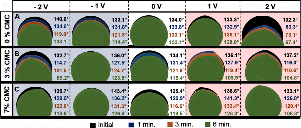 | ||
| Fig. 3 Dynamic contact angle measurements of pristine and modified 1 mol L−1 Li2SO4 electrolyte droplet adsorption on nonpolarized and polarized SX2A electrodes. | ||
As expected, the carbon electrode shows hydrophobic properties. After placing the electrolyte droplet without polarization, the measured contact angle was approximately 134° for both 1 mol L−1 pure Li2SO4 and Li2SO4 with 3% CMC. The electrolyte with 7% CMC had a contact angle of 125.5° (white background). For the non-modified electrolyte, the contact angle did not change during 6 minutes. However, the addition of CMC to the electrolyte significantly increased the electrolyte affinity to the carbon, as observed by a significant change in the contact angle over time; for the 3% additive, it decreased from 134.0° to 115.4°, and for the 7% CMC, it decreased from 125.4° to 118.5°. Additionally, the change in the droplet volume suggests spontaneous wetting of the carbon material. The application of potential has a significant influence on electrolyte behaviour. The cathodic polarization of non-modified 1 mol L−1 Li2SO4 induces gradual wetting of the electrode, as observed both by a change in the contact angle and a decrease in the electrolyte volume. However, the effect of electrolyte modified by the addition of CMC on cathodic polarization is somewhat different, and repulsion of the electrolyte is observed. The behaviour of the electrolyte at a polarization of −1 V might be explained by an ion exchange equilibrium. One may agree that at the interface of the electrolyte and electrode, part of the electrode is spontaneously wetted by the adsorbed electrolyte with a mixture of ions. When cathodic polarization is applied, cations move deeper into the pores of the materials and exchange with previously adsorbed anions. Due to increased viscosity, ion exchange is hindered, and a higher force needs to be applied to exchange them. The change in contact angle suggests similar changes in the affinity of electrolytes towards the electrode. Moreover, one must consider the increased viscosity and surface tension (@ 100 mN m−1) of electrolytes, making it more difficult to penetrate the electrode porous structure. The aforementioned consideration is more pronounced after increasing the cathodic polarization to −2 V. For electrolytes with 3% CMC, a stronger driving force results in faster wetting of the electrode. It is observed that both the contact angle and electrolyte droplet volume decrease. In the case of the electrolyte with 7% CMC, the repulsion effect is observed even when −2 V is applied.
The situation changes significantly for anodic polarization; for non-modified 1 mol L−1 Li2SO4 polarized at 1 V, no remarkable electrode wetting is observed. The contact angle changes negligibly, and the adsorbed volume is marginal. Such a behaviour is explained by the low affinity of anions towards carbon electrodes and low pore penetration ability, as observed by dilatometry experiments.60 However, the situation changes when a voltage of 2 V is applied; a significant change in droplet volume accompanied by a decrease in the contact angle is observed. For 0% and 3% CMC additive, the contact angle changes similarly, and the adsorbed volume is comparable. The only difference is the intensity of the process. However, when 7% CMC is added to the electrolyte, no wetting is observed. For 1 V polarization, there is an insignificant change in the contact angle, and no visible decrease in droplet volume. Even the application of 2 V does not induce penetration of the electrolyte into the electrode pores, despite the decrease in the contact angle from 133.1° to 108.8°. The behaviour of the electrolyte with 3% and 7% CMC additive under anodic polarization confirms the aforementioned consideration regarding the hindered ion exchange in the pores of the material. This shows that in the case of viscous electrolytes, the wetting of the electrode is strictly connected to the applied polarization, viscosity, and surface tension.
The electrochemical stability of modified and non-modified electrolytes was determined by linear sweep voltammetry (LSV) on a glassy carbon electrode. The voltammograms of pure 1 mol L−1 Li2SO4 and a sample with the addition of 7% CMC are shown in Fig. 4a and b.
 | ||
| Fig. 4 Potential window determination by LSV in a 3-electrode cell configuration: (a) pristine 1 mol L−1 Li2SO4 on glassy carbon, (b) 1 mol L−1 Li2SO4 with 7% CMC additive on glassy carbon, (c) comparison of potential limitation on different electrode materials. | ||
The maximum electrochemical window of the examined electrolytes was determined by significant current changes related to hydrogen and oxygen evolution. It can be observed that the addition of CMC does not introduce additional redox activity, and the LSV plot is typical for charge/discharge of the electrical double layer. The disturbance observed for a scan at 100 mV s−1 relates to the reduction and oxidation of hydrogen accumulated at the electrode/electrolyte interface. The limited diffusion of species in the modified electrolytes causes gas accumulation at the electrode surface. A comparison of the hydrogen/oxygen evolution potentials and theoretical maximum voltage shows no influence of CMC on these parameters. For the pristine electrolyte, the maximum voltage was 3.95 V, and for the modified electrolyte, it was 3.99 V. The abnormal values of the stability window exceed the thermodynamic correct value of 1.23 V because of the cell construction, where the overpotential, planar electrode, and excess electrolyte increase the overall result. Nevertheless, this method is ideal to observe the influence of electrolyte and electrode parameters on theoretical electrochemical stability. No significant differences are observed, regardless of whether CMC is present in the solution. However, in the case of the porous carbon electrodes, the influence of the CMC is more pronounced.
Fig. 4c presents a comparison of the maximum potential limitations of carbon electrodes estimated by the LSV method. In the case of typical mesoporous materials, SX2n-A and SX2A, during cathodic polarization, the hydrogen evolution potential is shifted towards more negative potentials when CMC is engaged. On the other hand, the oxygen evolution potential is not modified during anodic polarization. In the case of the microporous YP-80F material, hydrogen evolution is in the range of less negative values during cathodic polarization than in the case of the pristine electrolyte. Such behaviour might be explained by the aforementioned electrowetting properties of modified electrolytes. In the case of mesopores, the electrolyte is electrochemically adsorbed and may reach the micropores. The shift of the potential towards more negative values is caused by hydrogen sorption overpotential.26,61,62 In the case of anodic polarization, the shift of the potential is marginal, and it is in the same range of values as in the case of the glassy carbon electrode. The situation is somewhat different in the case of microporous YP-80F carbon, where during cathodic polarization, the potential limitation is shifted towards less negative values. Such behaviour might relate to the inaccessibility of micropores by electrolytes and induces hydrogen evolution in wider pores. That is why for microporous carbon, the hydrogen evolution potential is the same as for glassy carbon electrodes. During anodic polarization, the oxygen evolution limit is shifted towards more positive values. This might be related to a lack of oxygen groups on the surface of the electrode and their formation. As shown by He et al., the oxidation of carbon electrodes leads to the evolution of CO and CO2.63 This might mean that in the case of YP-80F, the generated oxygen is used to recombine on the electrode surface and build up as surface groups. This leads further to a shift of the gas evolution potential during anodic polarization towards more positive values.
The real voltage limitation of the prepared electrolytes was estimated by GITT (galvanostatic intermittent titration technique), as shown in Fig. 5. During the GITT experiment, the current is applied to the system for a given time. After the specific charge is reached (titrated), the polarization is interrupted by open-circuit conditions until the potential stabilizes (or for a given time). The process is repeated until the desired electrode potential (or the total charge titrated) is reached. This experiment allows the equilibrium potentials to be determined.
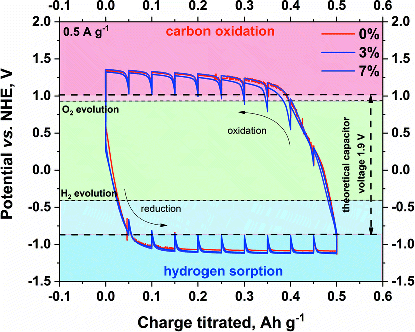 | ||
| Fig. 5 Determination of the maximum stability window of pristine and modified electrolytes on SX2A electrode by GITT (current regime – 0.5 A g−1). | ||
The experiment was conducted in a three-electrode setup. The technique itself enables the determination of equilibrium potentials of the electrodes. Briefly, a constant current of low magnitude is applied to the capacitor to reach the potential plateau. After the plateau is maintained, the current is terminated, and the electrode tends to reach its equilibrium potential. The maximum theoretical capacitor voltage was estimated by the offset of the resting potential during hydrogen sorption at the negative electrode and carbon oxidation at the positive electrode. The obtained value of the voltage window is 1.9 V. Such a value would be acceptable for the capacitor if the potentials were equally distributed among the electrodes. In the real system, as shown by other authors, the safe voltage limitation for a 1 mol L−1 Li2SO4 aqueous-based capacitor is 1.5–1.6 V. The presented result shows that the addition of CMC does not influence the performance26,64–66 of electrolytes on the carbon electrode. Although an earlier experiment showed shifting of the hydrogen evolution potential towards lower potential values for modified electrolytes, in this case, such behaviour is not observed. Consequently, for the full capacitor cell, the voltage limitation should be the same, regardless of the modification of the electrolyte. Additionally, the shape of the hydrogen desorption hysteresis is the same, meaning that an increase in viscosity did not influence the hydrogen sorption/desorption efficiency.
The capacitor performance with modified electrolytes was examined by galvanostatic charge/discharge at 0.5–10 A g−1 current regimes. The galvanostatic charge/discharge profiles from 0 to 1.6 V are presented in Fig. 6.
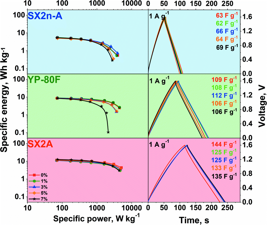 | ||
| Fig. 6 The graphs on the left are Ragone plots for different carbons with non-modified and CMC-modified 1 mol L−1 Li2SO4 electrolyte, and the graphs on the right are the corresponding galvanostatic charge/discharge profiles at the 1 A g−1 current regime. | ||
Typical linear voltage increases on charging and decreases on discharging are observed, confirming additional redox reaction occurrence, irrespective of the carbon material used and CMC content. Nonetheless, the hydrogen sorption phenomena characteristic for aqueous neutral electrolytes cannot be neglected. As the discharge time increases, the capacitance of the carbon material increases in the order SX2n-A, YP-80F, and SX2A. This difference is strictly connected with carbon differences in the surface area and pore accessibility. What may be noticed is that the CMC addition does not impact the shape of galvanostatic curves or the polarizability, recorded at 1 A g−1. The calculated power and energy values are presented on the Ragone plot.
For all carbons, the modification of the electrolyte did not influence the maximum energy recorded at a low power regime. This suggests that in all cases, the same active surface area is in contact with the electrolyte with the same capacitance. Such performance might be explained by the application of so-called conditioning cycles, just before the collection of data for the Ragone plot. The conditioning was performed to stabilize the system. For this reason, one cannot exclude the effect of gradual wetting of the electrode and pore penetration by the electrolyte during continuous charge/discharge cycles. However, this observation once more confirms that even highly viscous electrolytes might demonstrate satisfactory performance. Nevertheless, the structural properties of carbon have a significant influence on the maximum recorded power. On the one hand, in mesoporous carbon materials (SX2n-A and SX2A), the loss of power with an increase in electrolyte viscosity is marginal. However, the visible deterioration of the power in the case of SX2n-A carbon can be explained by the inaccessibility of the strict microporosity. This carbon is characterized by the smallest average micropore size ca. 0.7 nm, while in the case of SX2A and YP-80F carbon, the average pore size is ca. 0.9 and 1 nm respectively. On the other hand, for microporous carbon (YP-80F), the loss of power with an increase in viscosity is significant. This loss of power may be related to the accessibility of the electrolyte to the slit porosity without ensuring enough mesoporosity to serve as transport channels. During polarization, the continuous dragging of the electrolyte towards the pore surface is ongoing. As ions together with their solvation shell enter the micropores, they may also be accompanied by their counterions via so-called co-insertion. As the mixture of ions is attracted to the micropores, those contributing to charge storage must exchange places with “inert” ions. In the case of viscous electrolytes applied to microporous electrodes, the mobility of ions is limited, which results in limited power performance. In the case of mesoporous carbons, this effect is less visible, the ions have more space, and the exchange is easier. Therefore, in this case, the power is less affected by the viscosity of the electrolyte. This finding stresses that micropore accessibility is a power limiting factor in the case of viscous electrolytes.
The effect of viscosity was also examined in terms of internal pressure build-up. The measurement was performed for the capacitor placed in the thermostatic chamber at 30 °C. The electrochemical experiment involved galvanostatic charging to the desired voltage, followed by 2 h of constant voltage hold. The gas generation rate was then calculated as the slope of the pressure build-up during the voltage hold period. The change in the gas generation rate and leakage current with voltage is shown in Fig. 7a.
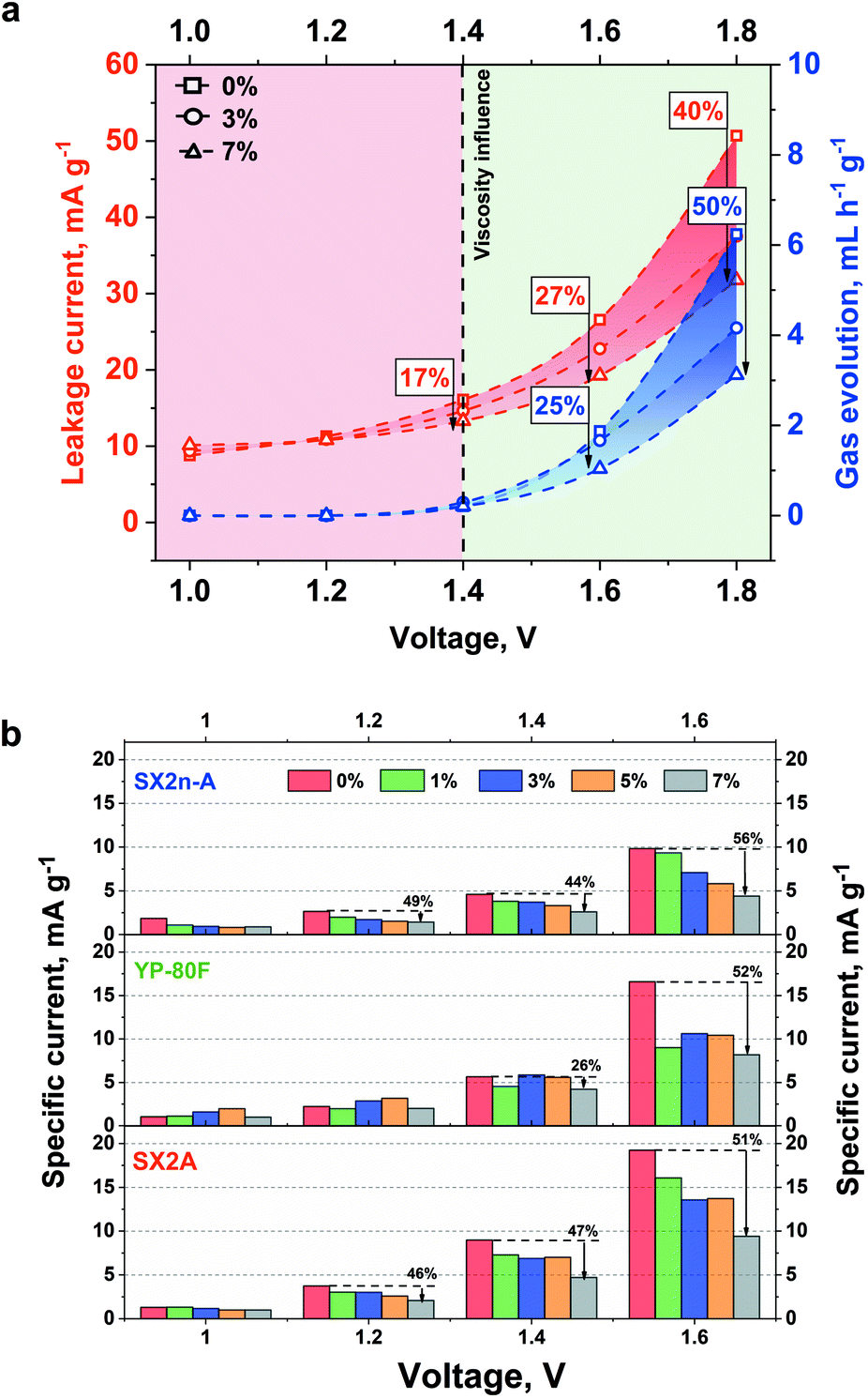 | ||
| Fig. 7 (a) Leakage current and volume of generated gases in the system working based on electrolytes with different viscosities. (b) Comparison of leakage current for selected carbons with increasing voltage limitation. | ||
A positive impact of increased viscosity on these two parameters is observed. With increasing viscosity, the internal pressure build-up and leakage current decrease. As the reduction of ionic mobility is not considered (no change of conductivity was recorded with increased viscosity), the leakage current reduction is most likely not connected with limited ion redistribution. Nonetheless, in the case of the aqueous electrolytes, the hydrogen sorption phenomenon needs to be here considered. Generally, at the negative electrode the water decomposes, and the generated hydrogen is ad-hoc adsorbed in the electrode microporosity. Additionally, as shown by He et al.,67 even at low voltage the CO and CO2 evolution might be observed. As the leakage current measurement is performed for 2 hours and the constant (equilibrated) current is reached, the electrode in such conditions might be considered as a reactor. In that case, the oxidation process will be performed until the equilibrium between substrate and product will be reached. In the case of the non-viscous electrolytes, the generated CO and CO2 can easily diffuse and can shift the equilibrium towards substrate, resulting in increased leakage current. In the case of viscous electrolytes the mobility of gaseous product is limited and less current is necessary to stabilize equilibrium in the system. In case of the YP-80F carbon due to high microporosity the CO and CO2 have limited mobility and the effect of electrolyte viscosity is less pronounced. However, in the case 1.6 V additional H2 recombination and evolution on negative electrode need to be considered. This case might be explained in similar manner as for CO and CO2 evolution. There is an equilibrium between ad-hoc hydrogen adsorption and recombination. In case of the viscous electrolytes the evacuation of gaseous product is limited this current of lower density is necessary to keep the electrode charged. The leakage current itself depends on the susceptibility of the ions for their redistribution in the EDL. The diffusion parameter at a given potential does not change with time at a given potential step. Therefore, this parameter is closely related to the value of the leakage current. The increased electrolyte viscosity should limit the gas diffusion from the material pores and thus reduce the value of the leakage current. Our results also prove this concept. We assume that narrow micropores (like in YP-80F) up to 1.4 V strongly limit the gas diffusion. In this case, the narrow pores constitute a barrier. The second factor is higher electrolyte viscosity and the addition of 7% CMC at 1.4 V reduced the leakage current by 26%. Voltage of 1.6 V is already high (so the driving force of the decomposition process) that the narrow pores are not able to hold the generated gases. In this case, viscosity begins to play a leading role (reduction of leakage current by 52%). In mesoporous materials and materials with a mixed pore content, viscosity begins to play a major role. Wider mesopores provide a more flexible path for gas diffusion. For SX2n-A and SX2A materials, the viscosity at relatively low voltage values (1, 1.2, 1.4 V) reduces gas diffusion. The pore width for mesoporous materials is not so small as to significantly limit the diffusion of gas.
The self-discharge measurement also showed interesting results. For YP-80F systems operating with 1 mol L−1 Li2SO4 and with the addition of 7% CMC (Fig. 8a), the self-discharge course is nearly the same. For SX2A-based capacitor, the addition of CMC slightly reduces the self-discharge, especially in the first 2 hours. The biggest difference was observed for SX2n-A, for which the CMC addition significantly reduces the self-discharge process. For 1 mol L−1 Li2SO4 the voltage dropped to 0.63, 0.7, 0.83 and 0.97 V for 1.0, 1.2, 1.4 and 1.6 V respectively. For electrolytes with 7% CMC, the voltage reached 0.79, 0.9, 1.02, and 1.1 V. Thus, one can conclude that to stabilize the voltage in the system based on mesoporous electrode material, the higher electrolyte viscosity should be applied. The stabilization most likely results from preventing the charge reorganization in the EDL once the polarization has subsided. As mentioned, the self-discharge process is caused by at least three types of processes: activation-controlled, diffusion-controlled, or so-called ohmic leakage. The diffusion-controlled process can be associated with the ions redistribution inside the micropores; activation-controlled processes are usually redox reactions resulting from the presence of pollutants, redox-active species in the electrolyte (or at electrode surface), and electrolyte decomposition. The ohmic leak usually occurs in the event of an internal short-circuit.
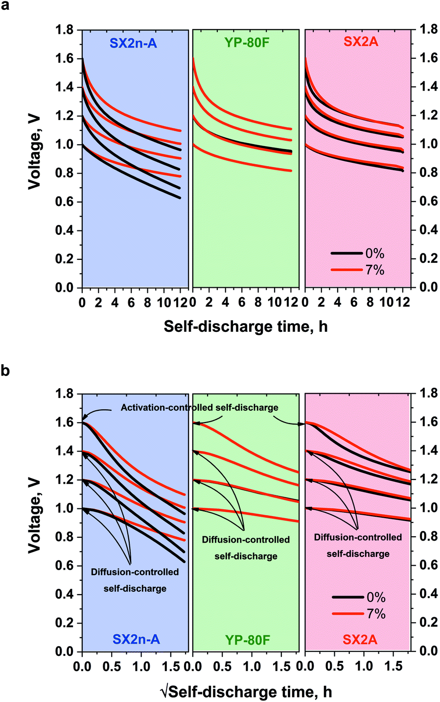 | ||
| Fig. 8 Self-discharge profiles of capacitors operating with 1 mol L−1 Li2SO4 and with 7% CMC addition dependence on (a) linear self-discharge time and (b) self-discharge time in a square-root time scale. | ||
Based on the profile of the voltage vs. the self-discharge square root time (Fig. 8b), it can be concluded that, in fact, there are two self-discharge processes in the tested systems. At a 1, 1.2, and 1.4 V the linear course of the self-discharge indicates nearly typical diffusion-controlled process. The non-linear curve for 1.6 V for all materials, regardless of the electrolyte viscosity, indicates the appearance of additional, parasitic reactions, such as electrolyte decomposition that govern and accelerate the self-discharge process.
The influence of the increased electrolyte viscosity on the long-term performance was tested by the application of 10000 charge/discharge cycles at 1 A g−1 current load (Fig. 9). One can easily notice that for all electrode materials, the capacitance reached 95% of its initial value after the same number of cycles. Therefore, we claim that no negative effect of increased electrolyte viscosity is observed.
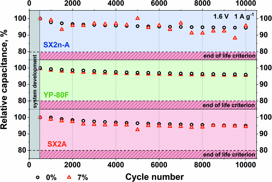 | ||
| Fig. 9 Long-term cycling test for a capacitor with 1 mol L−1 Li2SO4 and 7% CMC addition. | ||
4. Conclusions
This article describes the influence of increased electrolyte viscosity on electrochemical capacitor performance. The interaction between the viscous electrolyte and the porous carbon electrode is a complex relationship. It is postulated that unveiling its limiting factors can lead to further development of high-power-energy storage devices. The obtained results might be especially interesting in terms of the application of ionic liquids.One of the major conclusions that we should underline is that increase in the electrolyte viscosity does not significantly reduce the mobility of the ions (conductivity). However, the increased viscosity of the electrolyte reduces the electrowetting phenomenon; nonetheless, it depends on the polarization magnitude. The ion exchange in viscous electrolytes inside porous structures is certainly hindered. This might lead to insufficient pore penetration (especially for micropores) and deterioration of the electrochemical capacitor performance. It is recommended, before the actual operation of the capacitor based on high-viscous electrolyte, to condition the system. This solution should increase electrode wettability and device performance. The stability of the electrolytes verified with LSV technique shows that there are no significant differences between the low- and high-viscous electrolytes upon application of a glassy carbon electrode. While using a porous electrode, the differences become observable. However, they strongly depend on the carbon porous structure; surprisingly, mesoporous materials are more affected than microporous ones. The GITT technique is better suited to estimate the electrolyte stability window than the LSV technique, which tends to overestimate the potential stability. The increased viscosity has a marginal effect on the final voltage window of the device. The increased electrolyte viscosity does not affect the hydrogen sorption/desorption process efficiency. Moreover, in this article, we present that the impact of the electrolyte viscosity on the electrochemical capacitor energy and power performance is determined by the pore structure of carbon and pore accessibility. Higher electrolyte viscosity does not necessarily result in an energy decrease. Proper selection of the electrode material porosity is required. A significant advantage of increased viscosity (the case in which 7% CMC was used) is reducing the parasitic reactions of water decomposition at high voltage, as observed in the gas generation experiment (twice as low at 1.8 V). In a microporous AC based system higher electrolyte viscosity slightly reduce the discharge degree. However, a significant reduction in self-discharge by limiting the charge delocalization in the EDL was noticed in mesoporous materials. Another positive aspect seems to be the lack of electrolyte viscosity influence on the long-term performance stability, regardless of the electrode material porosity.
The presented results highlight the topic of viscous electrolyte/porous carbon interactions. Finally, these results give rise to be more sceptical to the overall statement that the viscosity being itself the limiting factor of electrochemical capacitor performance.
Conflicts of interest
There are no conflicts to declare.Acknowledgements
The authors would like to acknowledge the financial support from the European Research Council within the Starting Grant project (GA 759603) under the European Unions' Horizon 2020 research and innovation programme.Notes and references
- J. Khan and M. H. Arsalan, Renewable Sustainable Energy Rev., 2016, 55, 414–425 CrossRef.
- P. Simon and Y. Gogotsi, Nat. Mater., 2008, 7, 845–854 CrossRef CAS PubMed.
- R. Kötz and M. Carlen, Electrochim. Acta, 2000, 45, 2483–2498 CrossRef.
- E. Frackowiak and F. Beguin, Carbon, 2001, 39, 937–950 CrossRef CAS.
- B. E. Conway and W. G. Pell, J. Solid State Electrochem., 2003, 7, 637–644 CrossRef CAS.
- K. Fic, A. Platek, J. Piwek and E. Frackowiak, Mater. Today, 2018, 21, 437–454 CrossRef CAS.
- M. Mirzaeian, Q. Abbas, A. Ogwu, P. Hall, M. Goldin, M. Mirzaeian and H. F. Jirandehi, Int. J. Hydrogen Energy, 2017, 42, 25565–25587 CrossRef CAS.
- Y. Zhu, S. Murali, M. D. Stoller, K. J. Ganesh, W. Cai, P. J. Ferreira, A. Pirkle, R. M. Wallace, K. A. Cychosz, M. Thommes, D. Su, E. A. Stach and R. S. Ruoff, Science, 2011, 332, 1537–1541 CrossRef CAS PubMed.
- C. Niu, E. K. Sichel, R. Hoch, D. Moy and H. Tennent, Appl. Phys. Lett., 1997, 70, 1480–1482 CrossRef CAS.
- C. S. Du and N. Pan, Nanotechnology, 2006, 17, 5314–5318 CrossRef CAS.
- G. Moussa, C. M. Ghimbeu, P. L. Taberna, P. Simon and C. Vix-Guterl, Carbon, 2016, 105, 628–637 CrossRef CAS.
- R. Borgohain, J. C. Li, J. P. Selegue and Y. T. Cheng, J. Phys. Chem. C, 2012, 116, 15068–15075 CrossRef CAS.
- B. Anasori, M. R. Lukatskaya and Y. Gogotsi, Nat. Rev. Mater., 2017, 2, 16098 CrossRef CAS.
- Y. Gogotsi and B. Anasori, ACS Nano, 2019, 13, 8491–8494 CrossRef CAS PubMed.
- H. Marsh and F. Rodríguez-Reinoso, in Activated Carbon, 2006, pp. 13–86 Search PubMed.
- E. Frackowiak and F. Beguin, Carbon, 2002, 40, 1775–1787 CrossRef CAS.
- J. Lee, P. Srimuk, S. Fleischmann, X. Su, T. A. Hatton and V. Presser, Prog. Mater. Sci., 2019, 101, 46–89 CrossRef CAS.
- J. Krummacher, C. Schutter, L. H. Hess and A. Balducci, Curr. Opin. Electrochem., 2018, 9, 64–69 CrossRef CAS.
- F. Ghamouss, A. Brugere and J. Jacquemin, J. Phys. Chem. C, 2014, 118, 14107–14123 CrossRef CAS.
- E. Frackowiak, Q. Abbas and F. Beguin, J. Energy Chem., 2013, 22, 226–240 CrossRef CAS.
- K. Fic, M. Meller and E. Frackowiak, Electrochim. Acta, 2014, 128, 210–217 CrossRef CAS.
- V. Khomenko, E. Raymundo-Pinero, E. Frackowiak and F. Beguin, Appl. Phys. A: Mater. Sci. Process., 2006, 82, 567–573 CrossRef CAS.
- J. Menzel, K. Fic and E. Frackowiak, Prog. Nat. Sci.: Mater. Int., 2015, 25, 642–649 CrossRef CAS.
- A. Slesinski, C. Matei-Ghimbeu, K. Fic, F. Beguin and E. Frackowiak, Carbon, 2018, 129, 758–765 CrossRef CAS.
- L. Suo, O. Borodin, T. Gao, M. Olguin, J. Ho, X. Fan, C. Luo, C. Wang and K. Xu, Science, 2015, 350, 938–943 CrossRef CAS PubMed.
- K. Fic, A. Płatek, J. Piwek, J. Menzel, A. Ślesiński, P. Bujewska, P. Galek and E. Frąckowiak, Energy Storage Mater., 2019, 22, 1–14 CrossRef.
- M. P. Mousavi, B. E. Wilson, S. Kashefolgheta, E. L. Anderson, S. He, P. Buhlmann and A. Stein, ACS Appl. Mater. Interfaces, 2016, 8, 3396–3406 CrossRef CAS PubMed.
- A. Balducci, J. Power Sources, 2016, 326, 534–540 CrossRef CAS.
- A. Brandt, S. Pohlmann, A. Varzi, A. Balducci and S. Passerini, MRS Bull., 2013, 38, 554–559 CrossRef CAS.
- A. Balducci, U. Bardi, S. Caporali, M. Mastragostino and F. Soavi, Electrochem. Commun., 2004, 6, 566–570 CrossRef CAS.
- W. Y. Tsai, R. Y. Lin, S. Murali, L. L. Zhang, J. K. McDonough, R. S. Ruoff, P. L. Taberna, Y. Gogotsi and P. Simon, Nano Energy, 2013, 2, 403–411 CrossRef CAS.
- A. Lewandowski, A. Olejniczak, M. Galinski and I. Stepniak, J. Power Sources, 2010, 195, 5814–5819 CrossRef CAS.
- A. B. McEwen, S. F. McDevitt and V. R. Koch, J. Electrochem. Soc., 1997, 144, L84–L86 CrossRef CAS.
- Q. Zhang, J. P. Rong, D. S. Ma and B. Q. Wei, Energy Environ. Sci., 2011, 4, 2152–2159 RSC.
- T. Abdallah, D. Lemordant and B. Claude-Montigny, J. Power Sources, 2012, 201, 353–359 CrossRef CAS.
- A. Krause and A. Balducci, Electrochem. Commun., 2011, 13, 814–817 CrossRef CAS.
- H. N. Kwon, S. J. Jang, Y. C. Kang and K. C. Roh, Sci. Rep., 2019, 9, 1180 CrossRef PubMed.
- J. Barthel, R. Neueder and H. Roch, J. Chem. Eng. Data, 2000, 45, 1007–1011 CrossRef CAS.
- M. Anouti, E. Couadou, L. Timperman and H. Galiano, Electrochim. Acta, 2012, 64, 110–117 CrossRef CAS.
- P. Leung, A. A. Shah, L. Sanz, C. Flox, J. R. Morante, Q. Xu, M. R. Mohamed, C. P. de Leon and F. C. Walsh, J. Power Sources, 2017, 360, 243–283 CrossRef CAS.
- D. R. MacFarlane, N. Tachikawa, M. Forsyth, J. M. Pringle, P. C. Howlett, G. D. Elliott, J. H. Davis, M. Watanabe, P. Simon and C. A. Angell, Energy Environ. Sci., 2014, 7, 232–250 RSC.
- Z. Y. Li, M. S. Akhtar and O. B. Yang, J. Alloys Compd., 2015, 653, 212–218 CrossRef CAS.
- M. Kunze, S. Jeong, E. Paillard, M. Winter and S. Passerini, J. Phys. Chem. C, 2010, 114, 12364–12369 CrossRef CAS.
- L. Timperman, A. Vigeant and M. Anouti, Electrochim. Acta, 2015, 155, 164–173 CrossRef CAS.
- C. Zhong, Y. Deng, W. Hu, J. Qiao, L. Zhang and J. Zhang, Chem. Soc. Rev., 2015, 44, 7484–7539 RSC.
- W. T. Gu and G. Yushin, WIREs Energy Environ., 2014, 3, 424–473 CrossRef CAS.
- B. E. Conway, W. G. Pell and T. C. Liu, J. Power Sources, 1997, 65, 53–59 CrossRef CAS.
- W. G. Pell, B. E. Conway, W. A. Adams and J. de Oliveira, J. Power Sources, 1999, 80, 134–141 CrossRef CAS.
- A. M. Oickle and H. A. Andreas, J. Phys. Chem. C, 2011, 115, 4283–4288 CrossRef CAS.
- H. A. Andreas, J. Electrochem. Soc., 2015, 162, A5047–A5053 CrossRef CAS.
- A. Lewandowski, P. Jakobczyk, M. Galinski and M. Biegun, Phys. Chem. Chem. Phys., 2013, 15, 8692–8699 RSC.
- M. Y. Xia, J. H. Nie, Z. L. Zhang, X. M. Lu and Z. L. Wang, Nano Energy, 2018, 47, 43–50 CrossRef CAS.
- T. Tevi, H. Yaghoubi, J. Wang and A. Takshi, J. Power Sources, 2013, 241, 589–596 CrossRef CAS.
- L. B. Chen, H. Bai, Z. F. Huang and L. Li, Energy Environ. Sci., 2014, 7, 1750–1759 RSC.
- K. Fic, G. Lota and E. Frackowiak, Electrochim. Acta, 2010, 55, 7484–7488 CrossRef CAS.
- J. X. Li, Y. Gao, K. H. Han, J. H. Qi, M. Li and Z. C. Teng, Sci. Rep., 2019, 9, 17270 CrossRef PubMed.
- T. Sato, G. Masuda and K. Takagi, Electrochim. Acta, 2004, 49, 3603–3611 CrossRef CAS.
- C. Wolff, S. Jeong, E. Paillard, A. Balducci and S. Passerini, J. Power Sources, 2015, 293, 65–70 CrossRef CAS.
- N. Handa, T. Sugimoto, M. Yamagata, M. Kikuta, M. Kono and M. Ishikawa, J. Power Sources, 2008, 185, 1585–1588 CrossRef CAS.
- M. M. Hantel, V. Presser, R. Kotz and Y. Gogotsi, Electrochem. Commun., 2011, 13, 1221–1224 CrossRef CAS.
- L. Demarconnay, E. Raymundo-Pinero and F. Beguin, Electrochem. Commun., 2010, 12, 1275–1278 CrossRef CAS.
- Q. Gao, L. Demarconnay, E. Raymundo-Pinero and F. Beguin, Energy Environ. Sci., 2012, 5, 9611–9617 RSC.
- M. L. He, K. Fic, E. Frackowiak, P. Novak and E. J. Berg, Energy Environ. Sci., 2016, 9, 623–633 RSC.
- P. Ratajczak, K. Jurewicz, P. Skowron, Q. Abbas and F. Beguin, Electrochim. Acta, 2014, 130, 344–350 CrossRef CAS.
- Q. Abbas, P. Ratajczak, P. Babuchowska, A. Le Comte, D. Belanger, T. Brousse and F. Beguin, J. Electrochem. Soc., 2015, 162, A5148–A5157 CrossRef CAS.
- A. Platek, C. Nita, C. M. Ghimbeu, E. Frąckowiak and K. Fic, Electrochim. Acta, 2020, 338, 135788 CrossRef CAS.
- M. He, K. Fic, E. Frąckowiak, P. Novák and E. J. Berg, Energy Environ. Sci., 2016, 9, 623–633 RSC.
| This journal is © The Royal Society of Chemistry 2021 |