
Efficient spatial charge separation in unique 2D tandem heterojunction CdxZn1−xIn2S4–CdS–MoS2 rendering highly-promoted visible-light-induced H2 generation†
Jiakun
Wu‡
a,
Bowen
Sun‡
a,
Hui
Wang
c,
Yanyan
Li
a,
Ying
Zuo
d,
Wenjing
Wang
a,
Haifeng
Lin
 *a,
Shaoxiang
Li
b and
Lei
Wang
*ab
*a,
Shaoxiang
Li
b and
Lei
Wang
*ab
aKey Laboratory of Eco-chemical Engineering, Key Laboratory of Optic-electric Sensing and Analytical Chemistry of Life Science, Taishan Scholar Advantage and Characteristic Discipline Team of Eco-Chemical Process and Technology, College of Chemistry and Molecular Engineering, Qingdao University of Science and Technology, Qingdao 266042, P. R. China. E-mail: hflin20088@126.com
bShandong Engineering Research Center for Marine Environment Corrosion and Safety Protection, College of Environment and Safety Engineering, Qingdao University of Science and Technology, Qingdao 266042, P. R. China. E-mail: inorchemwl@126.com
cKey Laboratory of Rubber-Plastics of Ministry of Education, School of Polymer Science and Engineering, Qingdao University of Science and Technology, Qingdao 266042, P. R. China
dScientific Instrument Center, Shanxi University, Taiyuan 030006, P. R. China
First published on 9th December 2020
Abstract
Two-dimensional (2D) semiconductor nanostructures have exhibited great prospect as an efficient photocatalyst for solar-to-fuel application. In this work, a unique 2D tandem heterojunction consisting of ultrathin CdxZn1−xIn2S4 nanosheets coupled with rectangular CdS flakes and defect-rich MoS2 few-layered nanosheets was constructed for the first time. Remarkably, the efficient electron transfer channels present in the CdS/CdxZn1−xIn2S4 and CdxZn1−xIn2S4/MoS2 2D tandem heterojunctions facilitate the spatial separation and directional migration of photo-induced charge carriers effectively. Moreover, such 2D tandem heterojunction CdxZn1−xIn2S4–CdS–MoS2 is provided with excellent light harvesting capacity and abundant HER active sites from the defective MoS2 co-catalyst. These distinct advantages endow the optimized C0.15ZIS–5C–3M hybrid (5 wt% CdS, 3 wt% MoS2) with an exceptional photocatalytic H2 evolution reaction (HER) activity of 27.14 mmol h−1 g−1, approximately 47 times that of pure ZnIn2S4 and it is much superior to that of Pt-decorated C0.15ZIS–5C and most ZnIn2S4-based composites reported previously. A high HER apparent quantum yield (AQY) of 19.97% is achieved at λ = 400 nm. In addition, both the cycling and long-term HER measurements evidence the prominent stability of C0.15ZIS–5C–3M for H2 production. The results indicated here could pave the way for the exploitation of new 2D heterostructures toward highly-efficient solar conversion and utilization.
1. Introduction
Semiconductor photocatalysis for hydrogen (H2) generation via water-splitting holds enormous promise in ameliorating the worsening energy shortage and environment degradation as it can make direct use of the inexhaustible and clean solar energy.1–3 So far, numerous semiconductor photocatalysts such as metal oxides,4 sulfides,5 and nitrides6 have been developed systematically. Particularly, the metal sulfides like binary CdS and ternary ZnIn2S4 have received tremendous interests as their strong ability for visible-light harvest and appropriate band structures for water reduction. Yet, the photocatalytic H2 generation efficiency of metal sulfides is still unsatisfactory as a result of the rapid charge recombination along with photocorrosion issues.7 To surmount the above problems, several effective approaches, including morphological control,8,9 heteroatom doping,10,11 heterojunction construction,12,13etc. have been demonstrated to afford a significant promotion on the photocatalytic capability.Recently, two-dimensional (2D) nanostructures have aroused considerable research interests for photocatalysis due to their distinct structural virtues, for instance, the shortened bulk-to-surface transfer distance for photo-excited charge carriers, higher surface areas for the adsorption of reactant species, and more exposed catalytically active sites for redox reactions,14,15 all of which play crucial roles in improving the photocatalytic activity. Among various 2D metal sulfides, layer-structured ZnIn2S4 nanosheets have been widely studied as the matrix of heterostructures for photocatalytic H2 formation, seeing that the separation and transport of photogenerated charges can be dramatically accelerated by the built-in electric field formed at the heterointerfaces to obtain remarkably boosted photo-activity and stability.16 Nevertheless, the ZnIn2S4 products are usually produced as larger aggregates with lower surface area and active-site amount,17–19 thus it still remains a big challenge so far to fabricate the free-standing multi-component ZnIn2S4-based 2D heterostructures with controllable compositions and interface structures. In addition, serving as the key component of hybrid semiconductors, the co-catalyst has important roles in providing abundant reaction active sites and inhibiting the recombination of charge carriers through the interfacial heterojunctions.20 Hence, optimizing the microstructure of co-catalyst is a vital means to achieve superior photocatalytic ability. Of late, layered transition metal chalcogenides, especially MoS2, have been extensively utilized as the noble-metal-alternative co-catalyst for H2 evolution.21,22 Previous study confirms that,23 the HER active sites of MoS2 locate on the edges, while the basal planes are inactive for H2 formation. As a result, it is desirable to fabricate the MoS2 nanosheets co-catalyst with an ultrathin thickness and rich structural defects, which can bring about numerous additional active edge sites to facilitate the H2 production effectively.24,25 Therefore, the ultrathin defect-rich MoS2 nanosheets are expected to be a promising co-catalyst for the construction of highly-efficient 2D semiconductor heterostructures with remarkable HER activity, although the relevant investigations are rarely reported to now.
Herein, unique 2D tandem heterojunction CdxZn1−xIn2S4–CdS–MoS2 comprising CdxZn1−xIn2S4 ultrathin nanosheets coupled with rectangular CdS flakes and defect-rich MoS2 few-layered nanosheets was synthesized for the first time. These CdxZn1−xIn2S4–CdS–MoS2 composites are endowed with excellent light harvesting capacity, abundant HER active sites from the defective MoS2 nanosheets, as well as effective spatial isolation and directional transmission of photogenerated carriers through the efficient electron transfer channels generated in the CdS/CdxZn1−xIn2S4 and CdxZn1−xIn2S4/MoS2 2D tandem heterojunctions. As a result, when irradiated by visible-light (λ > 400 nm), the optimized CdxZn1−xIn2S4–CdS–MoS2 with 5 wt% CdS and 3 wt% MoS2 (C0.15ZIS–5C–3M) displays an outstanding HER activity, which is 47 times that of pure ZnIn2S4 and much better than that of Pt-loaded C0.15ZIS–5C and most ZnIn2S4-based hybrid photocatalysts ever documented. The present results demonstrate the controllable fabrication of uniform 2D tandem heterojunction CdxZn1−xIn2S4–CdS–MoS2 and the defect-rich MoS2 few-layered nanosheets as co-catalyst have great potential for highly-efficient photocatalytic H2 generation. Moreover, the detailed synthesis, characterizations on the morphology and structure, chemical valence states, and physicochemical properties of the prepared photocatalysts are also reported.
2. Experimental section
2.1. Materials
All chemicals used in the present work were analytically pure and supplied by Sinopharm Chemical Reagent, Co., Ltd.2.2. Synthesis of 2D CdxZn1−xIn2S4 ultrathin nanosheets
The CdxZn1−xIn2S4 ultrathin nanosheets were prepared via a facile ethanediol-assisted solvothermal method. Typically, calculated amounts of ZnCl2, CdCl2·2.5H2O, and InCl3·4H2O for the fabrication of 1 mmol CdxZn1−xIn2S4 (labeled as CxZIS, 0 ≤ x ≤ 1) were first dissolved into 60 mL ethylene glycol under stirring condition. Following this step, 4 mmol thioacetamide was put into the above solution and agitated to obtain a homogeneous mixture. Finally, the solution was sealed in a 100 mL autoclave to carry out the solvothermal reaction at 180 °C for 24 h. After reaction completed, the products were washed using deionized water and ethanol and dried at 70 °C for 5 h under vacuum condition.2.3. Synthesis of C0.15ZIS–CdS hybrid nanosheets
Typically, 0.2 g C0.15ZIS nanosheets were dispersed by sonication into 30 mL deionized water to form a suspension. Then, a certain quantity of CdCl2·H2O, C6H5Na3O7·2H2O, and CH4N2S (mole ratio of 1![[thin space (1/6-em)]](https://www.rsc.org/images/entities/char_2009.gif) :1.4:2) were dissolved into the above suspension under ultrasonic condition. After that, 2 mL NH3·H2O was decanted into the foregoing mixture, which was subsequently sealed in a 50 mL autoclave to perform the hydrothermal reaction at 180 °C for 24 h. When reaction finished, the products were rinsed separately by deionized water and ethanol and dried under vacuum condition. The obtained C0.15ZIS–CdS nano-hybrids are named as C0.15ZIS–yC, in which y denotes the weight percentage of CdS multiplied by 100.
:1.4:2) were dissolved into the above suspension under ultrasonic condition. After that, 2 mL NH3·H2O was decanted into the foregoing mixture, which was subsequently sealed in a 50 mL autoclave to perform the hydrothermal reaction at 180 °C for 24 h. When reaction finished, the products were rinsed separately by deionized water and ethanol and dried under vacuum condition. The obtained C0.15ZIS–CdS nano-hybrids are named as C0.15ZIS–yC, in which y denotes the weight percentage of CdS multiplied by 100.
2.4. Synthesis of defect-rich MoS2 nanosheets and C0.15ZIS–5C–MoS2 hybrid nanosheets
The MoS2 nanosheets with abundant structural defects were prepared by a hydrothermal method. Generally, appropriate amounts of (NH4)6Mo7O24·4H2O (1 mmol) and CH4N2S (30 mmol) were dissolved into 35 mL deionized water by vigorous stirring to get a transparent solution. After that, the above solution was sealed in an autoclave (50 mL) and heated at 200 °C for 24 h. Finally, the resultant MoS2 precipitate was washed using deionized water and ethanol and finally dried in a vaccum oven.The C0.15ZIS–5C–MoS2 composites were prepared with a self-assembly strategy. Specifically, 30 mL DMF suspension containing a certain amount of MoS2 nanosheets was prepared beforehand through an ultrasonic exfoliation treatment for 3 h. Following this step, 0.2 g C0.15ZIS–5C was mixed with the above suspension by ultrasonication and a 12 h agitation was performed to induce the self-assembly reaction. Finally, the resultant C0.15ZIS–5C–MoS2 hybrid nanosheets were washed by centrifugation with ethanol for three times. The C0.15ZIS–5C–MoS2 products were abbreviated as C0.15ZIS–5C–zM, where z equals to the mass fraction of MoS2 multiplied by 100.
2.5. Synthesis of Pt-loaded C0.15ZIS–5C hybrid nanosheets via photo-deposition
The Pt-decorated C0.15ZIS–5C hybrid nanosheets were fabricated via an in situ photocatalytic reduction reaction. Prior to irradiation, 10 mg C0.15ZIS–5C was dispersed by ultrasonication into 100 mL aqueous solution comprising hole-scavenger. After that, a certain amount of H2PtCl6 was added and the mixture was then transferred to the reactor and evacuated for 0.5 h to get rid of the dissolved air. The light source for photo-deposition was provided by a Xe lamp (300 W, PLS-SXE 300D) installed with a cut-off filter. Finally, Pt-loaded C0.15ZIS–5C hybrid nanosheets can be obtained after the photo-reduction reaction for 1 h.2.6. Characterization
Powder X-ray diffraction (XRD) signals were examined by an X-ray diffractometer (Rigaku D/max 2500 PC) employing the scanning rate of 5° min−1. Scanning electron microscopy (SEM) measurements were carried out on a ZEISS MERLIN Compact scanning electron microscope. Transmission electron microscopy (TEM), high-resolution TEM (HRTEM), dark-field scanning TEM (STEM), as well as the energy-dispersive X-ray spectroscopy (EDX) results were tested by a transmission electron microscope (JEOL JEM-2100F). Atomic force microscopy (AFM) results were obtained through the use of an atomic force microscope (Bruker MultiMode 8). Brunauer–Emmett–Teller (BET) tests were carried out with an automatic adsorption machine (Micromeritics TriStar II 3020). Electron paramagnetic resonance (EPR) data was obtained by a Bruker A300 spectrometer operating at 113 K. X-ray photoelectron spectroscopy (XPS) spectra were measured using a Thermo Fisher ESCALAB 250 Xi spectrometer. Ultraviolet-visible (UV-vis) absorption was detected on a Shimadzu UV 3600 spectrometer. Photoluminescence (PL) signals were collected with an Edinburgh FLS 980 fluorescence spectrophotometer adopting a 365 nm exciting light.2.7. Photocatalytic H2 generation activity
Photocatalytic H2 production test was carried out with a Labsolar-6A apparatus purchased from Beijing Perfectlight Technology Co., Ltd. The reaction temperature was adjusted as 6 °C by a circulating water-bath device. A PLS-SXE 300D Xe lamp (300 W, 400 nm cutoff filter) was employed to give the required irradiation. For a routine test, 10 mg photocatalyst was dispersed by sonication into 100 mL aqueous solution comprising 10 vol% lactic acid. Then, the reaction solution was vacuumized for 0.5 h to remove the dissolved air. At a specific interval, the generated H2 was detected by a GC-7900 online gas chromatograph. Besides, 0.35 M Na2S/0.25 M Na2SO3, 10 vol% triethanolamine (TEOA), and 0.375 M ascorbic acid solutions were also used for reaction so as to examine the effect of hole scavenger on the HER property of photocatalyst. HER apparent quantum yield (AQY) under 400 nm irradiation was determined on the basis of the following equation:
2.8. Electrochemical and photoelectrochemical tests
To investigate the electrochemical and photoelectrochemical properties of synthesized photocatalysts, a CHI 660E electrochemical analyzer with a standard three-electrode configuration was used for measurement. Pt plate was used as counter-electrode, and Ag/AgCl was chosen as reference electrode. For working electrode, the preparation of which was implemented according to the procedure bellow: firstly, the photocatalyst ink was drop-casted onto a fluorine-doped tin oxide (FTO) glass slide (contacting area of 2 cm2) and then dried naturally, before calcining at 450 °C for 1 h under flowing N2. Mott–Schottky curves were measured employing 0.5 M Na2SO4 aqueous solution as electrolyte under the testing conditions of 0.01 V amplitude and 500 Hz frequency. Photocurrent response was examined in 10 vol% lactic acid aqueous solution adopting the bias potential of 0.5 V. Electrochemical impedance spectroscopy (EIS) data were collected under open circuit potentials using 0.5 M Na2SO4 aqueous solution as electrolyte. The measurement was performed with the testing conditions of 0.005 V amplitude and 0.1–106 Hz frequency.3. Results and discussion
3.1. Catalyst characterization
The CdxZn1−xIn2S4–CdS–MoS2 2D heterostructures were synthesized through a three-step strategy (Fig. 1). In the first step, ultrathin CdxZn1−xIn2S4 solid solution nanosheets were fabricated through the solvothermal reaction in ethylene glycol. Secondly, by using CdxZn1−xIn2S4 nanosheets as substrate, rectangular CdS flakes were grown uniformly onto CdxZn1−xIn2S4 nanosheets under hydrothermal conditions to form the CdxZn1−xIn2S4–CdS hybrid nanosheets. Finally, the defect-rich MoS2 nanosheets obtained via a solvothermal method were exfoliated by ultrasonication for 3 h, which were then combined with the CdxZn1−xIn2S4–CdS to produce the unique CdxZn1−xIn2S4–CdS–MoS2 ternary hybrids by means of the self-assembly process under stirring condition. | ||
| Fig. 1 Diagram illustrating the synthesis of CdxZn1−xIn2S4–CdS–MoS2 composites. | ||
The crystalline structure of products was confirmed by XRD tests. According to Fig. 2a, the diffraction peaks of synthesized ZnIn2S4 can be indexed as hexagonal ZnIn2S4 (JCPDS no. 65-2023). Interestingly, the diffraction signals of CdxZn1−xIn2S4 (x = 0.05, 0.10, 0.15, and 0.20) were successively moved toward lower angle with the increasing Cd ratio (inset), which indicates that the products were Cd-doped ZnIn2S4 instead of the mixture of ZnIn2S4 and CdIn2S4.26 It is well known that, the Cd2+ possesses a larger radius (0.97 Å) than that of Zn2+ (0.74 Å). Therefore, the lattice expansion happened after the Zn2+ sites of ZnIn2S4 crystal were occupied by Cd2+, resulting in the low-angle-shift of XRD peaks.27,28 However, when the ZnCl2 was completely replaced by CdCl2 for synthesis, the resultant product was CdIn2S4 (JCPDS no. 27-0060) mixed with some CdS (JCPDS no. 80-0006) and CdCO3 (JCPDS no. 52-1547) (Fig. S1†). The XRD patterns of MoS2, CdS, C0.15ZIS, as well as their hybrids were displayed in Fig. 2b. The XRD signals of individual CdS and C0.15ZIS are assigned to the wurtzite CdS and hexagonal ZnIn2S4, corresponding to JCPDS no. 65-3414 and no. 65-2023, respectively. Compared to bulk MoS2 (JCPDS no. 77-1716), the layer-spacing of as-synthesized MoS2 nanosheets was enlarged as the two peaks of (002) and (004) were shifted to lower angles.29 The increased layer-spacing of MoS2 nanosheets could contribute to the exposure of more unsaturated S atoms on the edge sites, which serve as the active sites for H2 evolution. Moreover, the expanded layer-spacing of MoS2 nanosheets makes their exfoliation much easier to generate abundant active S atoms to promote the HER efficiently. We can see that the XRD patterns of C0.15ZIS–5C and C0.15ZIS–5C–3M exhibit the signals originating from C0.15ZIS component, while the diffraction peaks of CdS and MoS2 couldn't be observed due to their lower loading amounts.30 By increasing the MoS2 content to 10 wt%, the (002) peak of MoS2 appeared in the diffraction pattern of C0.15ZIS–5C–10M composite.
 | ||
| Fig. 2 (a) XRD patterns of CdxZn1−xIn2S4 nanosheets. (b) XRD patterns of MoS2, CdS, C0.15ZIS, C0.15ZIS–5C, C0.15ZIS–5C–3M, and C0.15ZIS–5C–10M. | ||
Fig. 3 presents the ultraviolet-visible (UV-vis) absorption spectra of MoS2, CdS, ZnIn2S4, C0.15ZIS, C0.15ZIS–5C, and C0.15ZIS–5C–3M. It is found that the ZnIn2S4 displays an optical absorption edge around 462.3 nm, which is moved to 471.9 nm when the C0.15ZIS is concerned. By comparison to ZnIn2S4 and C0.15ZIS, the light-harvesting capability of CdS is significantly enhanced and the corresponding optical absorption edge is evidently red-shifted to 567.6 nm. Noticeably, the MoS2 is provided with an intense light-absorption stretching across the ultraviolet-light to visible-light bands. After the C0.15ZIS was hybridized by CdS and MoS2, the optical absorption edges of produced C0.15ZIS–5C and C0.15ZIS–5C–3M composites are sequentially moved toward longer wavelengths to show a notably improved light-absorption property. Generally, the bandgap of semiconductors can be determined by the Kubelka–Munk equation of (Ahν)n = K(hν − Eg) (A: absorbance, hν: photon energy, K: constant, Eg: bandgap, n: 0.5 and 2 for indirect-transition and direct-transition semicondutors, respectively).31 By employing the Kubelka–Munk method, the bandgaps of CdS, ZnIn2S4, C0.15ZIS, and MoS2 can be calculated to be 2.29, 2.82, 2.75, and 1.40 eV, respectively (Fig. S2†).
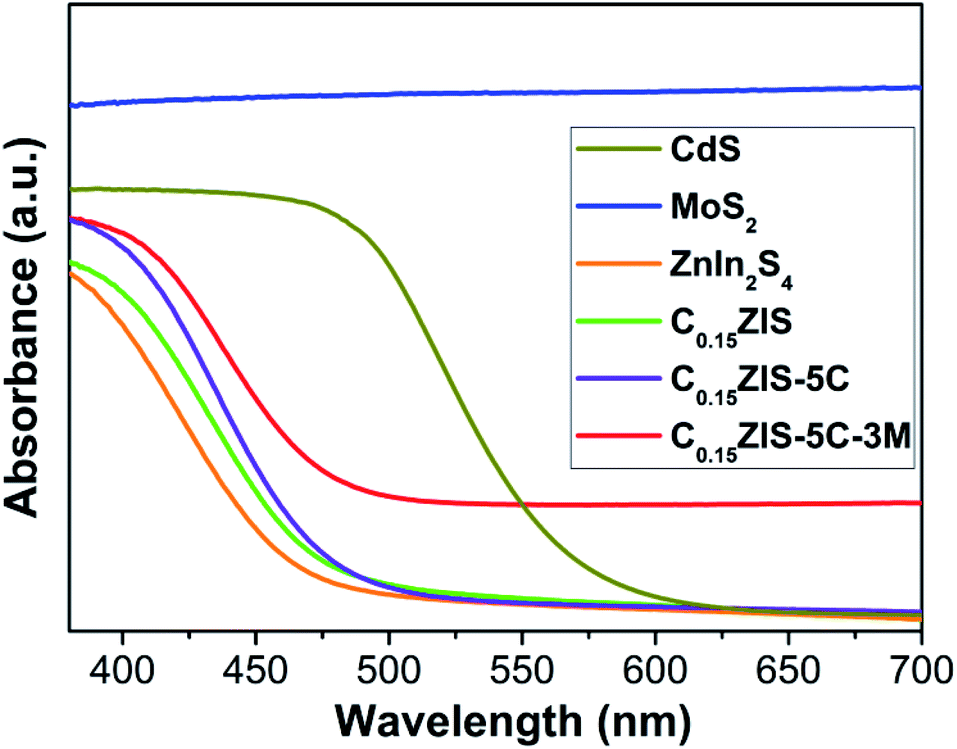 | ||
| Fig. 3 UV-vis absorption spectra of MoS2, CdS, ZnIn2S4, C0.15ZIS, C0.15ZIS–5C, and C0.15ZIS–5C–3M. | ||
SEM observations were carried out to discern the macroscopic morphology of synthesized ZnIn2S4 and C0.15ZIS. One can find from Fig. 4a that, the synthesized ZnIn2S4 is featured by a uniform sheet-like structure. Moreover, as revealed by Fig. 4b, the free-standing sheet-like structure was maintained after the ZnIn2S4 was doped by Cd to form C0.15ZIS. It is noteworthy that, the free-standing ZnIn2S4 or C0.15ZIS nanosheets prepared in this work are quite different from those reported in the literatures,17,32,33 which are frequently the large-sized aggregates with lower Brunauer–Emmett–Teller (BET) surface area and active-site number, unfavorable for the photocatalytic application. The regular 2D morphology of C0.15ZIS nanosheets were further confirmed by TEM measurements (Fig. 4c). Additionally, the top and bottom facets are identified as (001) plane according to the fast Fourier transform (FFT) result of the HRTEM graph of a lying C0.15ZIS nanosheet (Fig. 4d). In addition, the thickness of C0.15ZIS nanosheets is estimated to be 4.0 nm from the AFM test results shown in Fig. 4e and f. These ultrathin C0.15ZIS nanosheets are in possession of a large BET surface area (Fig. S3 and Table S1†), which enables them to serve as an ideal matrix to construct novel 2D semiconductor heterostructures with outstanding photocatalytic properties. In addition, elements Cd, Zn, In, and S are uniformly distributed in C0.15ZIS nanosheets as proved by the STEM and corresponding EDX results in Fig. 4g.
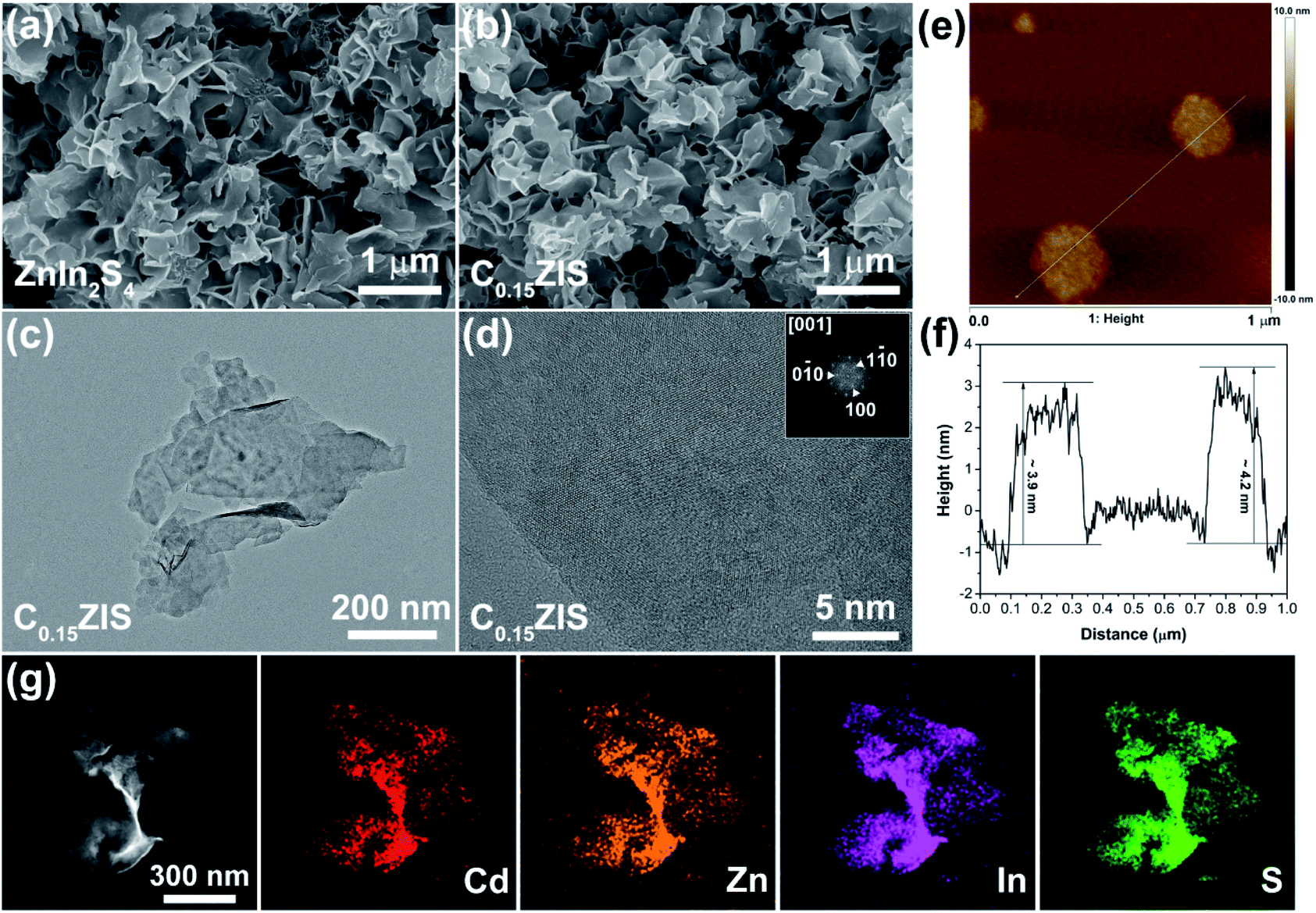 | ||
| Fig. 4 (a and b) SEM images of (a) ZnIn2S4 and (b) C0.15ZIS nanosheets. (c) TEM image, (d) HRTEM image, (e) AFM image and (f) corresponding height profile, as well as (g) STEM and corresponding EDX elemental mapping results of the C0.15ZIS nanosheets. | ||
The microstructure of the C0.15ZIS–CdS–MoS2 hybrids was studied by TEM tests. Fig. 5a exhibits the typical morphology of the C0.15ZIS–5C–3M composite, in which many rectangular flakes are uniformly distributed on the surface of bigger nanosheets. On the basis of HRTEM analyses in Fig. 5b, the lattice spacing of 0.33 nm is assigned to (100) plane of C0.15ZIS nanosheet substrate (JCPDS no. 65-2023). The rectangular flakes display a 0.35 nm lattice spacing, corresponding to (100) plane of CdS (JCPDS no. 65-3414). According to the synthetic procedure of C0.15ZIS–CdS, pure CdS nanocrystals with irregular shapes were obtained in the absence of C0.15ZIS nanosheets (Fig. S4†), which confirms the importance of C0.15ZIS substrate in guiding the formation of rectangular CdS flakes. Meanwhile, the lattice spacing of 0.95 nm is attributed to the expanded layers ((002) plane) of MoS2 nanosheets (JCPDS no. 77-1716), coinciding well with the XRD results (Fig. 2b). Additionally, there are numerous structural defects (such as lattice distortion and missing, etc.) existed in the MoS2 few-layered nanosheets as indicated by the cyan dashed circles (Fig. 5b, c and S5†). What's more, the electron paramagnetic resonance (EPR) signal at g = 2.008 demonstrates the presence of S vacancies in the MoS2 nanosheets (Fig. S6†).34 Similarly, the lattice fringes of rectangular flakes in Fig. 5c own the spacings of 0.31 and 0.35 nm, belonging to the (101) and (100) facets of CdS (JCPDS no. 65-3414), respectively. Besides, the lattice spacing of 0.95 nm also confirms the formation of expanded layers in the MoS2 component. The above TEM, HRTEM, and EPR data evidence unambiguously the presence of C0.15ZIS nanosheets, rectangular CdS flakes, and defect-rich MoS2 nanosheets in the C0.15ZIS–5C–3M hybrid. Besides, the element distribution of Cd, Zn, In, Mo, and S of C0.15ZIS–5C–3M was corroborated by the STEM and corresponding EDX results shown in Fig. 5d.
 | ||
| Fig. 5 (a) TEM and (b and c) HRTEM images, (d) dark-field STEM photo and corresponding EDX elemental mapping results of the C0.15ZIS–5C–3M composite. | ||
XPS investigation was carried out to examine the chemical valence states of surface species for C0.15ZIS–CdS–MoS2 composites. Here, we select the C0.15ZIS–5C–10M as an example for interpretation. As shown in Fig. 6a, elements Cd, Zn, In, Mo, and S were co-existed in C0.15ZIS–5C–10M composite. The Cd 3d spectrum displays two signals at 404.9 and 411.6 eV (Fig. 6b), which are consistent with that of Cd2+ state.35 For Zn 2p spectrum (Fig. 6c), the doublet signals locating at 1021.5–1044.6 eV can be ascribed to the Zn2+ species.36 Meanwhile, the In 3d5/2 and 3d3/2 signals are observed at 444.7 and 452.2 eV (Fig. 6d), confirming the formation of In3+ ions.37 In the Mo 3d spectrum (Fig. 6e), two sets of doublet peaks around 228.1–231.4 eV and 228.9–232.2 eV are assigned to the Mo4+ and Mo5+, respectively.30,38 By comparison to pure C0.15ZIS and MoS2 (Fig. S7a–c and e†), the binding energies of Cd 3d, Zn 2p, In 3d, and Mo 3d peaks of C0.15ZIS–5C–10M are all changed, implying that there exist electron transfer and strong interaction between the C0.15ZIS, CdS, and MoS2 components of C0.15ZIS–5C–10M.39 Regarding to S 2p spectrum, the doublet signals at 161.3–162.4 eV are related to the S2− ligands,40 while the doublet peaks at 162.7–163.5 eV match well with the S22− species.41 As documented in the literature,41,42 the presence of Mo5+ ions is usually accompanied by the generation of S22− species, and both Mo5+ and S22− are the active sites for H2 evolution. Moreover, the Mo5+ and S22− can also be found in individual MoS2 (Fig. S7f†), which indicates that these Mo5+ and S22− active sites should originate from the MoS2 component. Hence, the C0.15ZIS–CdS–MoS2 composites decorated with MoS2 co-catalyst are anticipated to exhibit a superior activity toward photocatalytic H2 production.
 | ||
| Fig. 6 (a) XPS survey and (b) Cd 3d, (c) Zn 2p, (d) In 3d, (e) Mo 3d, and (f) S 2p spectra of the C0.15ZIS–5C–10M hybrid. | ||
3.2. Photocatalytic activity and stability
The visible-light-excited (λ > 400 nm) H2 evolution activity for the prepared samples was studied when lactic acid was used as the hole scavenger. It is seen from Fig. 7a and S8a† that, the MoS2, CdS, CdIn2S4, and ZnIn2S4 are all in possession of lower activities toward photocatalytic H2 evolution. Compared with pristine ZnIn2S4, the HER activity of CdxZn1−xIn2S4 is increased because of the enhanced light-harvesting (Fig. 3), and the C0.15ZIS with 15 mol% Cd-doping achieves the maximum HER rate of 2.31 mmol h−1 g−1 (Fig. S9a and b†). The H2 evolution activity of C0.20ZIS is lowered in relation to that of C0.15ZIS, probably due to the smaller BET surface area of the former (Table S1†) that gives rise to less active sites for H2 evolution. Moreover, after the C0.15ZIS was hybridized by CdS to form the C0.15ZIS–CdS composites, the HER performance is notably heightened and the C0.15ZIS–5C with 5 wt% CdS presents the optimal activity of 7.69 mmol h−1 g−1 (Fig. S9c and d†). The H2 evolution activity of C0.15ZIS–CdS is reduced at a higher CdS content, which may result from the excess CdS coverage that diminishes the charge separation efficiency and catalytically active sites on C0.15ZIS. Interestingly, the HER property of C0.15ZIS–5C can be further dramatically improved when it was decorated by MoS2 to produce C0.15ZIS–5C–MoS2. Fig. S9e and f† exhibit that, the HER activity of C0.15ZIS–5C–MoS2 is elevated with the raising MoS2 concentration and the highest HER rate of 27.14 mmol h−1 g−1 is achieved at the 3 wt%-MoS2 (C0.15ZIS–5C–3M). The apparent quantum yield (AQY) for H2 evolution of C0.15ZIS–5C–3M under 420 nm irradiation is calculated as 11.80%, which is raised to 19.97% when the H2 generation reaction is driven by 400 nm irradiation (Fig. S10†). However, further increasing the MoS2 content leads to a decreased HER capability. The possible reason is that excess MoS2 will screen the light-absorption of CdS and C0.15ZIS, which reduces the amount of photo-induced charge carriers and thus cuts down the H2 production efficiency accordingly. The H2 formation rate of C0.15ZIS–5C–3M is about 47 times that of pure ZnIn2S4 and it exceeds that of most known ZnIn2S4-based photocatalysts (Table S2†). Additionally, the C0.15ZIS–5C–3M is far more active than the C0.15ZIS–5C–3 wt% Pt as well as the bi-component C0.15ZIS–5C, C0.15ZIS–3M, and CdS–MoS2 with the same CdS/MoS2 ratio as that in C0.15ZIS–5C–3M (Fig. 7a), suggesting that the excellent photocatalytic activity of C0.15ZIS–5C–3M results from the synergistic cooperation of the C0.15ZIS, CdS, and MoS2 components. On the other hand, the effect of sacrificial agents on the HER capability of C0.15ZIS–5C–3M was investigated. We can find from Fig. 7b and S8b† that, the H2 production of C0.15ZIS–5C–3M is facilitated more effectively in lactic acid solution as compared with that in other solutions containing ascorbic acid, TEOA, or Na2S/Na2SO3. The pH value of lactic acid, ascorbic acid, TEOA, and Na2S/Na2SO3 solutions used for HER is around 1.3, 2.5, 10.8, and 13.4, respectively. Therefore, the higher HER activity of C0.15ZIS–5C–3M in lactic acid solution could result from the presence of more H+ ions for H2 production due to the smaller pH value of lactic acid solution than the other three solutions. In addition, under long-time irradiation, the steady increase on the evolved H2 amount of C0.15ZIS–5C–3M (Fig. 7c) evidences that the C0.15ZIS–5C–3M possesses favorable stability for sustainable H2 production from photocatalytic water-splitting. Furthermore, the HER cycling stability of C0.15ZIS–5C–3M was examined utilizing the same photocatalyst and testing conditions. After five consecutive measurements, no obvious alteration was observed for the HER activity of C0.15ZIS–5C–3M (Fig. 7d), which also manifests the outstanding photocatalytic stability of C0.15ZIS–5C–3M for H2 evolution.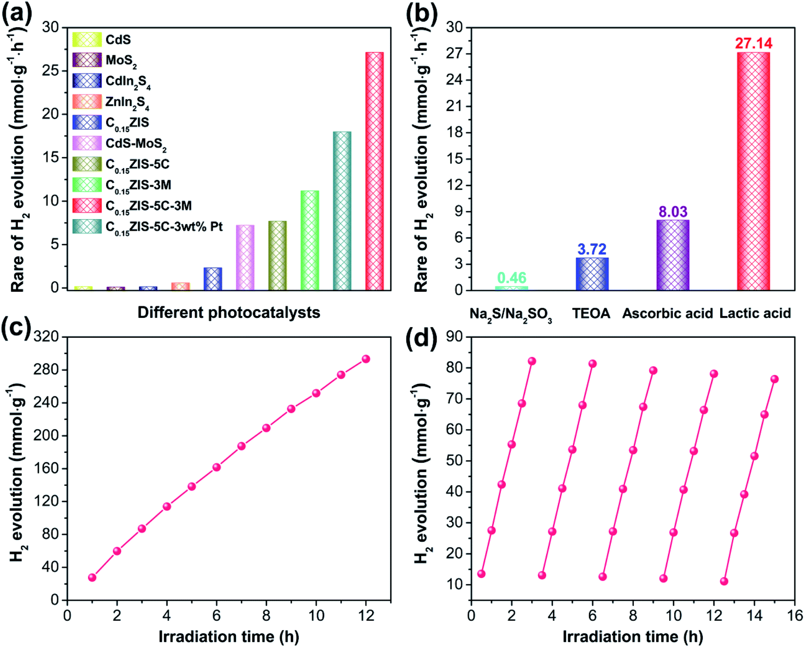 | ||
| Fig. 7 (a) Photocatalytic H2 evolution rates of different samples. (b) HER activity of C0.15ZIS–5C–3M in different sacrificial-agent solutions. (c) Long-term and (d) cycling H2 generation durability of C0.15ZIS–5C–3M. | ||
The structure of C0.15ZIS–5C–MoS2 after H2 production reaction was also characterized by XRD, HRTEM, and XPS measurements. As displayed in Fig. S11,† the XRD signals of used C0.15ZIS–5C–3M were nearly unchanged with respect to the original one, certifying that the crystal structure of C0.15ZIS–5C–3M was well preserved after catalytic reaction. Moreover, the TEM and HRTEM images in Fig. S12† verify the existence of C0.15ZIS nanosheets, CdS rectangular flakes, and defect-rich MoS2 nanosheets in the recovered C0.15ZIS–5C–3M hybrid. Besides, the XPS spectra in Fig. S13† demonstrate that, the chemical constituents and related valence states of C0.15ZIS–5C–10M were maintained after HER test. Therefore, the above XRD, HRTEM, and XPS results jointly corroborate the prominent stability of the C0.15ZIS–5C–MoS2 composites toward visible-light-driven H2 evolution.
3.3. Photocatalytic mechanism
The excellent photocatalytic activity of C0.15ZIS–5C–3M composite could be associated with its superior charge separation capability, which was verified by the photocurrent, EIS, and PL measurements. It is seen from Fig. 8a, the C0.15ZIS–5C–3M displays a much higher photocurrent density than the MoS2, CdS, and C0.15ZIS, suggesting that the charge recombination is effectively impeded by C0.15ZIS–5C–3M as compared with the latter three.43 Moreover, the EIS Nyquist profiles in Fig. 8b exhibit that, the arc diameter of C0.15ZIS–5C–3M is reduced in relation to that of CdS, MoS2, and C0.15ZIS. It is well known that,44 a smaller Nyquist arc diameter is indicative of a lowered charge-transfer resistance. Thus, the charge-transfer resistance of C0.15ZIS–5C–3M is decreased in contrast with that of CdS, MoS2, and C0.15ZIS, which originates from the promoted transfer and separation of photogenerated charges, conforming to the photocurrent results. In addition, the PL spectra of CdS, C0.15ZIS, and C0.15ZIS–5C–3M were tested as shown in Fig. 8c. All these three samples present the signals around 470 and 520 nm, corresponding to the excitonic and trap-state emissions, respectively.30,45 By comparison to CdS and C0.15ZIS, the PL emission of C0.15ZIS–5C–3M was notably quenched, manifesting that the latter has a better capability for depressing the charge recombination,46 which is in agreement with the photocurrent response and EIS analyses. Therefore, the enhanced charge transfer and separation of C0.15ZIS–5C–3M is responsible for its outstanding performance toward photocatalytic reaction.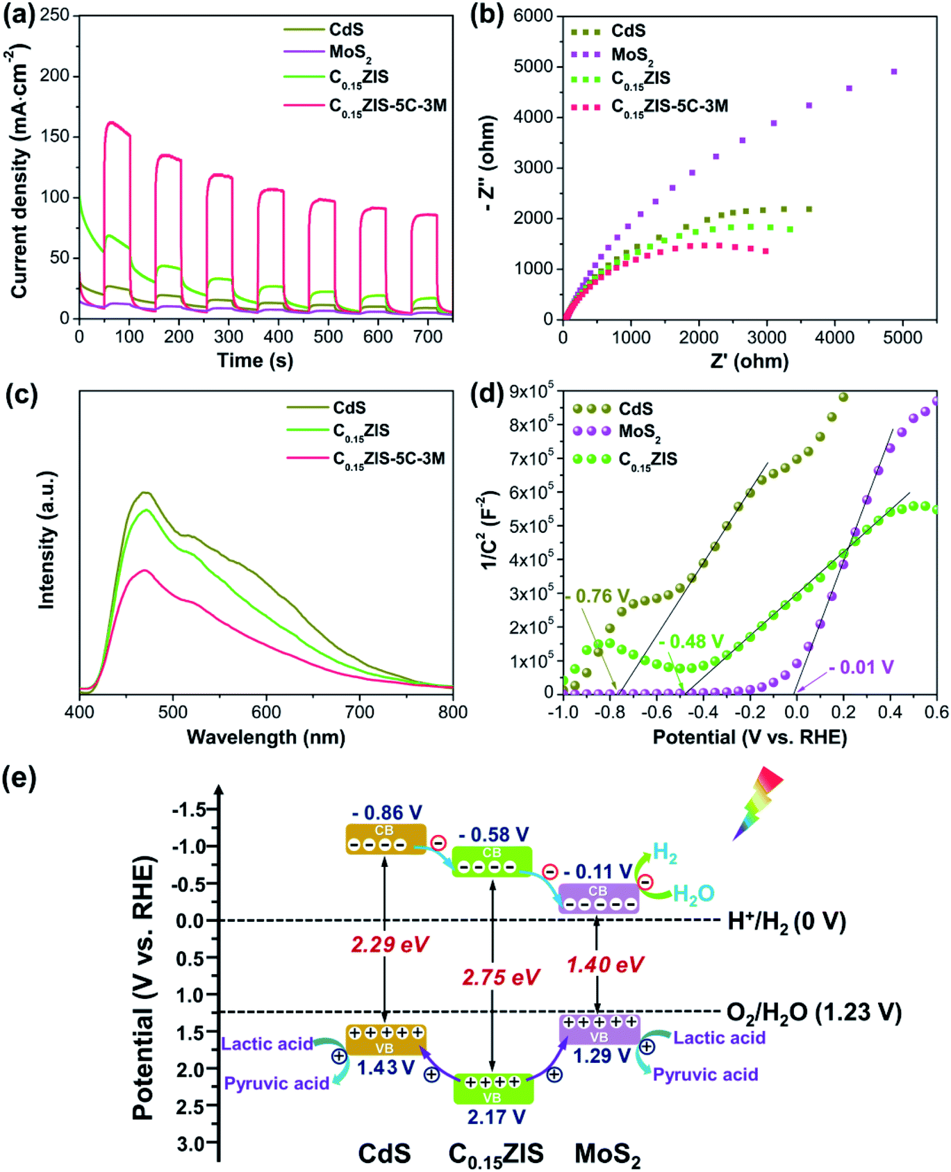 | ||
| Fig. 8 (a) Transient photocurrent responses, (b) EIS Nyquist curves, and (c) PL spectra of MoS2, CdS, C0.15ZIS, and C0.15ZIS–5C–3M. (d) Mott–Schottky plots of MoS2, CdS, and C0.15ZIS. (e) Schematic energy band alignments of MoS2, CdS, and C0.15ZIS. | ||
To probe into the origin for the heightened charge separation of C0.15ZIS–CdS–MoS2 composites, the electronic band structures of C0.15ZIS, CdS, and MoS2 were investigated. The Mott–Schottky curves of C0.15ZIS, CdS, and MoS2 were collected using three different testing frequencies (Fig. 8d and S14†), and the corresponding flat-band potentials can be determined by the tangent intersection with horizontal axis as −0.48, −0.76, and −0.01 V vs. RHE, respectively. Moreover, the positive slopes of Mott–Schottky curves indicate the C0.15ZIS, CdS, and MoS2 are n-type semiconductors.47 It is known that, the conduction band minimum (CBM) of n-type semiconductors is 0.1 V more negative in relation to their corresponding flat-band potential.48 Hence, the CBM potential of C0.15ZIS, CdS, and MoS2 are estimated as −0.58, −0.86, and −0.11 V vs. RHE, respectively. Combining the CBM positions of C0.15ZIS, CdS, and MoS2 with their bandgaps (Fig. S2†), the corresponding band alignments were established. As shown in Fig. 8e, the CBM level of C0.15ZIS is higher than that of MoS2 but lower than that of CdS, whilst the valence band maximum (VBM) level for C0.15ZIS shifts downward with respect to MoS2 and CdS. Therefore, after visible-light excitation, the photogenerated electrons will first flow from the CB of CdS to the CB of C0.15ZIS, and subsequently to the CB of MoS2. Meanwhile, photo-holes in the valence band (VB) of C0.15ZIS could migrate to the VB of MoS2 and CdS due to the existed potential difference. Because of the above charge-transfer processes, the recombination of photo-induced charge carriers can be effectively hindered, leading to significantly improved photocatalytic efficiency. Besides, the stronger visible-light-absorption abilities of CdS and MoS2 (Fig. 3) help to enhance the light-harvesting of C0.15ZIS–CdS–MoS2. What's more, there exist abundant HER active sites in the defect-rich MoS2 nanosheets (Fig. 5b, c, 6, and S5†). Benefiting from the above advantages, the C0.15ZIS–CdS–MoS2 hybrids demonstrate an outstanding photocatalytic property toward visible-light-induced H2 evolution.
4. Conclusions
In summary, unique C0.15ZIS–CdS–MoS2 2D tandem heterojunction photocatalyst was fabricated for the first time, in which the C0.15ZIS ultrathin nanosheets were coupled by CdS rectangular flakes and defect-rich MoS2 few-layered nanosheets. Detailed characterizations reveal that this type of 2D tandem heterojunction is critical to the highly-improved HER performance. Benefiting from the presence of efficient electron-transfer channels in the CdS/CdxZn1−xIn2S4 and CdxZn1−xIn2S4/MoS2 2D tandem heterojunctions, the spatial separation and directional migration of photo-excited charge carriers are facilitated effectively as confirmed by the PL, photocurrent response, and EIS results. Meanwhile, the excellent light harvesting and abundant HER active sites are also very conducive to the exceptional photocatalytic activity of CdxZn1−xIn2S4–CdS–MoS2 hybrid. The optimized C0.15ZIS–5C–3M hybrid (5 wt% CdS and 3 wt% MoS2) shows the maximum HER rate of 27.14 mmol h−1 g−1, approximately 47 times that of pure ZnIn2S4 and it is much superior to that of Pt-loaded C0.15ZIS–5C and the most known ZnIn2S4-based photocatalysts. The apparent quantum yield (AQY) for H2 production reaches up to 19.97% at λ = 400 nm. In addition, the C0.15ZIS–5C–3M is in possession of outstanding cycling and long-term H2 production stabilities under visible-light irradiation. The findings reported here could inspire the rational design of novel 2D semiconductor heterostructures to facilitate the efficient solar conversion and utilization.Conflicts of interest
There are no conflicts to declare.Acknowledgements
The authors thank the financial support from the National Natural Science Foundation of China (51802170, 51772162, 21801150), the Natural Science Foundation of Shandong Province (ZR2019MB001, ZR2019JQ14), the Youth Innovation and Technology Foundation of Shandong Higher Education Institutions, China (2019KJC004), the Taishan Scholar Project of Shandong Province (ts201712047), the Special Fund Project to Guide Development of Local Science and Technology by Central Government, and the Taishan Scholar Program of Advantage and Characteristic Discipline Team of Eco-Chemical Process and Technology.Notes and references
- S. B. Wang, Y. Wang, S. L. Zhang, S. Q. Zang and X. W. Lou, Adv. Mater., 2019, 31, 1903404 CrossRef CAS PubMed.
- Z. Wang, C. Li and K. Domen, Chem. Soc. Rev., 2019, 48, 2109 RSC.
- J. A. Nasir, Z. U. Rehman, S. N. A. Shah, A. Khan, I. S. Butler and C. R. A. Catlow, J. Mater. Chem. A, 2020, 8, 20752 RSC.
- Y. Z. Wei, J. Y. Wang, R. B. Yu, J. W. Wan and D. Wang, Angew. Chem., Int. Ed., 2019, 58, 1422 CrossRef CAS PubMed.
- Y. J. Yuan, D. Q. Chen, Z. T. Yu and Z. G. Zou, J. Mater. Chem. A, 2018, 6, 11606 RSC.
- M. Xiao, B. Luo, M. Lyu, S. C. Wang and L. Z. Wang, Adv. Energy Mater., 2018, 8, 1701605 CrossRef.
- Y. Xia, B. Cheng, J. J. Fan, J. G. Yu and G. Liu, Small, 2019, 15, 1902459 CrossRef PubMed.
- Y. Z. Wei, N. L. Yang, K. K. Huang, J. W. Wan, F. F. You, R. B. Yu, S. H. Feng and D. Wang, Adv. Mater., 2020, 7, 2002556 CrossRef PubMed.
- J. Xiong, J. Di and H. M. Li, J. Mater. Chem. A, 2020, 8, 12928 RSC.
- R. Shi, H. F. Ye, F. Liang, Z. Wang, K. Li, Y. X. Weng, Z. S. Lin, W. F. Fu, C. M. Che and Y. Chen, Adv. Mater., 2018, 30, 1705941 CrossRef PubMed.
- S. Li, L. J. Zhang, T. F. Jiang, L. P. Chen, Y. H. Lin, D. J. Wang and T. F. Xie, Chem.–Eur. J., 2014, 20, 311 CrossRef CAS PubMed.
- S. Chandrasekaran, L. Yao, L. B. Deng, C. Bowen, Y. Zhang, S. Chen, Z. Q. Lin, F. Peng and P. X. Zhang, Chem. Soc. Rev., 2019, 48, 4178 RSC.
- X. F. Ning and G. X. Lu, Nanoscale, 2020, 12, 1213 RSC.
- Z. Y. Sun, N. Talreja, H. C. Tao, J. Texter, M. Muhler, J. Strunk and J. F. Chen, Angew. Chem., Int. Ed., 2018, 57, 7610–7627 CrossRef CAS PubMed.
- J. Di, J. Xiong, H. M. Li and Z. Liu, Adv. Mater., 2018, 30, 1704548 CrossRef PubMed.
- Y. P. Yuan, L. W. Ruan, J. Barber, S. C. J. Loo and C. Xue, Energy Environ. Sci., 2014, 7, 3934–3951 RSC.
- Y. Q. He, H. Rao, K. P. Song, J. X. Li, Y. Yu, Y. Lou, C. G. Li, Y. Han, Z. Shi and S. H. Feng, Adv. Funct. Mater., 2019, 29, 1905153 CrossRef CAS.
- S. S. Li, D. S. Dai, L. Ge, Y. Q. Gao, C. C. Han and N. Xiao, Dalton Trans., 2017, 46, 10620 RSC.
- G. Ma, C. Q. Shang, M. L. Jin, L. L. Shui, Q. G. Meng, Y. G. Zhang, Z. Zhang, H. Liao, M. Li, Z. H. Chen, M. Z. Yuan, X. Wang, C. Y. Wang and G. F. Zhou, J. Mater. Chem. C, 2020, 8, 2693 RSC.
- X. F. Zhou, Y. X. Fang, X. Cai, S. S. Zhang, S. Y. Yang, H. Q. Wang, X. H. Zhong and Y. P. Fang, ACS Appl. Mater. Interfaces, 2020, 12, 20579 CrossRef CAS PubMed.
- K. Chang, X. Hai and J. H. Ye, Adv. Energy Mater., 2016, 6, 1502555 CrossRef.
- X. Zong, H. J. Yan, G. P. Wu, G. J. Ma, F. Y. Wen, L. Wang and C. Li, J. Am. Chem. Soc., 2008, 130, 7176 CrossRef CAS PubMed.
- T. F. Jaramillo, K. P. Jørgensen, J. Bonde, J. H. Nielsen, S. Horch and I. Chorkendorff, Science, 2007, 317, 100 CrossRef CAS PubMed.
- J. Z. Chen, X. J. Wu, L. S. Yin, B. Li, X. Hong, Z. X. Fan, B. Chen, C. Xue and H. Zhang, Angew. Chem., Int. Ed., 2015, 54, 1210–1214 CrossRef CAS PubMed.
- J. F. Xie, H. Zhang, S. Li, R. X. Wang, X. Sun, M. Zhou, J. F. Zhou, X. W. Lou and Y. Xie, Adv. Mater., 2013, 25, 5807–5813 CrossRef CAS PubMed.
- F. Yang, N. N. Yan, S. Huang, Q. Sun, L. Z. Zhang and Y. Yu, J. Phys. Chem. C, 2012, 116, 9078 CrossRef CAS.
- X. N. Xing, Q. Zhang, Z. Huang, Z. J. Lu, J. B. Zhang, H. Q. Li, H. B. Zeng and T. Y. Zhai, Small, 2016, 12, 874 CrossRef CAS PubMed.
- H. F. Ye, R. Shi, X. Yang, W. F. Fu and Y. Chen, Appl. Catal., B, 2018, 233, 70 CrossRef CAS.
- J. F. Xie, J. J. Zhang, S. Li, F. Grote, X. D. Zhang, H. Zhang, R. X. Wang, Y. Lei, B. C. Pan and Y. Xie, J. Am. Chem. Soc., 2013, 135, 17881 CrossRef CAS PubMed.
- X. L. Yin, L. L. Li, W. J. Jiang, Y. Zhang, X. Zhang, L. J. Wan and J. S. Hu, ACS Appl. Mater. Interfaces, 2016, 8, 15258 CrossRef CAS.
- M. Nowak, B. Kauch and P. Szperlich, Rev. Sci. Instrum., 2009, 80, 046107 CrossRef CAS PubMed.
- Y. Z. Wang, D. Chen, L. S. Qin, J. H. Liang and Y. X. Huang, Phys. Chem. Chem. Phys., 2019, 21, 25484 RSC.
- Z. Y. Zhang, K. C. Liu, Z. Q. Feng, Y. N. Bao and B. Dong, Sci. Rep., 2016, 6, 19221 CrossRef CAS PubMed.
- C. Du, Q. Zhang, Z. Y. Lin, B. Yan, C. X. Xia and G. W. Yang, Appl. Catal., B, 2019, 248, 193 CrossRef CAS.
- M. Y. Xing, B. C. Qiu, M. M. Du, Q. H. Zhu, L. Z. Wang and J. L. Zhang, Adv. Funct. Mater., 2017, 27, 1702624 CrossRef.
- M. Zhou, S. B. Wang, P. J. Yang, Z. S. Luo, R. S. Yuan, A. M. Asiri, M. Wakeel and X. C. Wang, Chem.–Eur. J., 2018, 24, 18529 CrossRef CAS PubMed.
- S. J. Peng, P. N. Zhu, V. Thavasi, S. G. Mhaisalkar and S. Ramakrishna, Nanoscale, 2011, 3, 2602 RSC.
- H. F. Lin, B. W. Sun, H. Wang, Q. Q. Ruan, Y. L. Geng, Y. Y. Li, J. K. Wu, W. J. Wang, J. Liu and X. Wang, Small, 2019, 15, 1804115 CrossRef PubMed.
- S. M. Zhu, Y. N. Zhang, X. J. Qian, X. X. Wang and W. Y. Su, Appl. Surf. Sci., 2020, 504, 144396 CrossRef CAS.
- L. Wei, Y. J. Chen, Y. P. Lin, H. S. Wu, R. S. Yuan and Z. H. Li, Appl. Catal., B, 2014, 144, 521 CrossRef CAS.
- J. H. Xiong, Y. H. Liu, D. K. Wang, S. J. Liang, W. M. Wu and L. Wu, J. Mater. Chem. A, 2015, 3, 12631 RSC.
- Y. H. Chang, R. D. Nikam, C. T. Lin, J. K. Huang, C. C. Tseng, C. L. Hsu, C. C. Cheng, C. Y. Su, L. J. Li and D. H. C. Chua, ACS Appl. Mater. Interfaces, 2014, 6, 17679 CrossRef CAS PubMed.
- D. Q. Zeng, L. Xiao, W. J. Ong, P. Y. Wu, H. F. Zheng, Y. Z. Chen and D. L. Peng, ChemSusChem, 2017, 10, 4624 CrossRef CAS PubMed.
- S. B. Wang, B. Y. Guan and X. W. D. Lou, J. Am. Chem. Soc., 2018, 140, 5037 CrossRef CAS PubMed.
- T. Simon, N. Bouchonville, M. J. Berr, A. Vaneski, A. Adrović, D. Volbers, R. Wyrwich, M. Döblinger, A. S. Susha, A. L. Rogach, F. Jäckel, J. K. Stolarczyk and J. Feldmann, Nat. Mater., 2014, 13, 1013 CrossRef CAS PubMed.
- Q. M. Sun, N. Wang, J. H. Yu and J. C. Yu, Adv. Mater., 2018, 30, 1804368 CrossRef PubMed.
- F. K. Meng, J. T. Li, S. K. Cushing, M. J. Zhi and N. Q. Wu, J. Am. Chem. Soc., 2013, 135, 10286 CrossRef CAS PubMed.
- C. C. Ling, X. J. Ye, J. H. Zhang, J. F. Zhang, S. J. Zhang, S. G. Meng, X. L. Fu and S. F. Chen, Sci. Rep., 2017, 7, 28174428 Search PubMed.
Footnotes |
| † Electronic supplementary information (ESI) available: Bandgaps, N2 adsorption–desorption isotherms, EPR signal, Mott–Schottky curves, tables summarizing the BET surface areas and reported HER data, as well as additional XRD patterns, XPS spectra, TEM images, and HER activities. See DOI: 10.1039/d0ta10564c |
| ‡ Equal contribution to this work. |
| This journal is © The Royal Society of Chemistry 2021 |