
Recent advances in and comprehensive consideration of the oxidation half reaction in photocatalytic CO2 conversion
Yanjie
Wang
 a and
Tao
He
*ab
a and
Tao
He
*ab
aCAS Key Laboratory of Nanosystem and Hierarchical Fabrication, CAS Center for Excellence in Nanoscience, National Center for Nanoscience and Technology, Beijing 100190, China. E-mail: het@nanoctr.cn
bUniversity of Chinese Academy of Sciences, Beijing 100049, China
First published on 17th November 2020
Abstract
Photocatalytic conversion of CO2 into value-added chemicals is a promising method to tackle the global warming issue and ease the need for sustainable energy. To date, much effort has been devoted to improving the electron behavior of the reduction process for effective CO2 reduction. However, it is often overlooked that the simultaneous control of electrons and holes is more meaningful and beneficial for an overall photocatalytic reaction, since the two half reactions driven respectively by electrons and holes are equally important. Considering that much less attention has been paid to the oxidation half reaction, this review specifically highlights the approaches and strategies for promoting the oxidation half reaction that accompanies CO2 conversion, which can in turn improve the CO2 photoreduction performance. In detail, a comprehensive discussion on regulating the hole behavior (e.g. lifetime and driving force) is presented in three parts, viz. materials design (element modification, oxidation co-catalysts, and Z-scheme structures), electron donors (H2O and sacrificial electron donors), and reaction system management (high value-added oxidation reaction). We anticipate that this review will offer a systematic summary of the past achievements and general considerations for the oxidation half reaction occurring during CO2 reduction, which will provide possible routes and/or implications for scientists to further improve the CO2 conversion efficiency.
 Yanjie Wang | Yanjie Wang received her PhD in physical chemistry from the National Center for Nanoscience and Technology, China, in 2018. After that she joined the National Center for Nanoscience and Technology. Her current research focuses on the rational design of nanomaterials and their application in sustainable energy. |
 Tao He | Tao He received his PhD from the Institute of Chemistry, Chinese Academy of Sciences in 2002. After postdoctoral training at the Weizmann Institute of Science and Rice University, he joined the National Center for Nanoscience and Technology, China in 2009. He is now a professor at the National Center for Nanoscience and Technology, China. He was selected by the Hundred Talents Program (Chinese Academy of Sciences) in 2009. His current research interest mainly focuses on R&D of novel photoelectric functional nanomaterials and related devices that can efficiently utilize light energy at a relatively low cost, specifically for the photocatalytic reduction of CO2. |
1 Introduction
Considering the ever-growing threat from CO2 emission into the atmosphere, it is critical to balance the carbon cycle in nature. Carbon conversion is a feasible strategy to reduce CO2 emission and simultaneously meet the increasing demand for sustainable energy. To this end, photocatalytic CO2 reduction to value-added chemicals has attracted ever-increasing attention for decades as a green technique. Because the CO2 molecule is extremely stable (ΔGθf = −394.4 kJ mol−1), a significant amount of energy input is required for activation and hence a highly efficient photocatalyst is needed.1 In the past decades, enormous efforts have been made to realize photocatalytic CO2 conversion by developing semiconductor photocatalysts, such as metal oxides, metal sulfides and metal nitrides, which possess a conduction band potential negative enough to drive the CO2 reduction reaction (CO2RR) (Fig. 1). To achieve high conversion efficiency, extensive efforts have been devoted to regulating the photogenerated electron behavior to boost the CO2RR both thermodynamically and kinetically. Approaches like doping, loading cocatalysts and fabricating heterojunctions have been widely employed.2,3 However, the photocatalytic CO2RR performance is still below expectations and far from commercial applications, implying that other factors should be considered.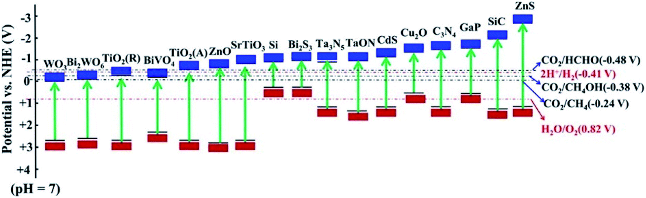 | ||
| Fig. 1 Energy band diagram for semiconductors used in the CO2 reduction. Reprinted with permission from ref. 4. Copyright 2019, American Chemical Society. | ||
It is to be noted that an overall photocatalytic reaction involves both reduction and oxidation half-reactions driven respectively by photogenerated electrons and holes. So the photocatalysis is highly dependent on the behavior of electrons and holes (such as generation, separation/recombination and transport) and surface redox reaction, with electron–hole recombination as the dominant loss and surface reaction as the rate-determining step. The overall catalytic efficiency can be improved by promoting the charge separation and surface redox reaction via controlling the behavior of either electrons or holes. In this regard, modulation of hole behavior is as important as that of electrons for the photocatalysis. Taking CO2 photoconversion in H2O as an example,5 in the oxidation part (2H2O + 4h+ → O2 + 4H+), it requires four holes to remove four protons from two H2O molecules for the production of one O2 molecule, with a minimum required potential of 0.82 V vs. SHE. Hence, besides the CO2RR, the oxidation part is also a bottleneck for improved solar-to-chemical conversion efficiency.
Moreover, the mobility of photogenerated holes is usually lower than that of electrons in a semiconductor.6 Increasing the hole mobility can accelerate the oxidation half reaction (OHR) and leave more electrons and protons for the reduction half reaction. Zou et al. proved this by combining experimental and theoretical calculation results, i.e., higher hole mobility on the {100} facets of ZnGa2O4 is favorable for efficient H2O oxidation, leading to more protons for CO2 reduction to CH4.7 In addition, some of the oxidation processes are relatively slow (around 0.3 s for H2O),8 and the holes accumulated on the photocatalyst surface may accelerate the charge recombination, which will slow down the overall photocatalytic process. Kamat pointed out the importance of trapping or scavenging either charge carrier to accelerate the dynamics of the opposite carrier.9 Hence, promoting hole consumption will also help suppress the electron–hole recombination and thus accelerate the CO2RR.
For the time being, most of the attention is focused on regulating the electron behavior in CO2RR research, while much less attention is focused on the modulation of the hole behavior. Some approaches have been used to promote the OHR in the CO2RR like introducing sacrificial electron donors, loading oxidation cocatalysts, and establishing Z-scheme structures.10–12 All of these approaches can either enhance the hole-involving reactions or promote the behavior of both electrons and holes synergistically. Despite the availability of many review articles on the general aspects of the CO2RR like photocatalyst design and mechanism study,5,13–17 there is a lack of comprehensive summary of the general considerations and progress of these studies on the OHR.
Herein, we present a systematic review of the state of the art of the OHR involved in the CO2RR study. An overview of the topics covered in this article is provided in Fig. 2. Firstly, materials design, which aims to improve the trapping ability or maintain the high driving force of photogenerated holes, is presented in detail. Then, electron donors are discussed, including the widely used H2O and various other sacrificial electron donors. The CO2RR occurring in aqueous solution is highlighted, and studies on the stoichiometric yield of reduction and oxidation products are systematically analyzed. Furthermore, tandem systems aiming to fully utilize the overall reaction, for which both oxidation and reduction half reactions are meaningful, are covered. This review aims to present a detailed discussion on the OHR in the CO2RR study, which can help researchers understand CO2 reduction at the full scale and further inspire them to achieve high conversion efficiency.
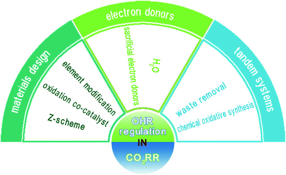 | ||
| Fig. 2 Overview of the topics discussed in this review. | ||
2 Materials design for boosting oxidation reactions
Materials design is a common way to boost the photocatalytic activity by tuning the charge behavior, such as redox potential and charge generation/separation efficiency. The performance of a single pure photocatalyst is limited by the possible backward reactions on neighboring active sites and its intrinsic properties that cannot meet all the requirements. To further improve the CO2RR activity, modification of the photocatalytic systems is desired, which can increase the driving force of the charge carrier and spatially separate the two half reactions. The common approaches include functionalizing the photocatalyst with other elements, loading cocatalysts and interfacial engineering (forming heterostructures). Since advances in materials design for improved CO2RR have already been thoroughly summarized in the literature, here we only focus on the strategies and approaches of managing the associated OHR.2.1 Element modification
Introducing foreign elements (i.e., doping) into the lattice of a photocatalyst is an effective means to narrow down the bandgap by creating acceptor levels above the valence band (VB) or donor levels below the conduction band (CB). Various semiconductors, especially those with wide bandgap values, have been employed as host materials, such as TiO2, SrTiO3, WO3, C3N4 and Fe2O3.18–22 However, the influence of doping on the charge behavior, especially on the hole behavior, is still a subject of debate. Even though the visible-light response can be enhanced and it was claimed that most photogenerated holes can avoid being trapped at the N-induced gap,23 a number of reports have pointed out that undesired effects may emerge as a result of doping, resulting in decreased photoactivity. Many doping methods rely on raising the energy position of the VB. For example, it is popular to partially replace O in metal oxides by N or C to raise the VB position for narrowing the bandgap. Taking N doping in TiO2 as an example, since the N 2p orbital has higher energy than the O 2p orbital, the additional intraband state from N 2p lies above the VB of TiO2 (Fig. 3). Dynamics of the charge carriers derived from time-resolved absorption spectra show that the states induced by N doping may result in electron–hole recombination and reduce the oxidation power of photogenerated holes,18 leading to decreased water oxidation performance.5,18 Therefore, when introducing a foreign element into a photocatalyst, it is desirable to consider its influence on the VB position of the host material and thereby the hole behavior simultaneously.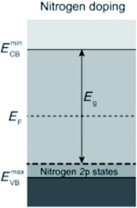 | ||
| Fig. 3 Semiconductor with dopant states above the VB. Reprinted with permission from ref. 5. Copyright 2013, Wiley-VCH. | ||
Halogen elements (especially Cl−) incorporated on semiconductors are able to help trap the photogenerated holes, facilitate the charge separation and thereby improve the photocatalytic CO2RR; however, the explanations in various studies on how Cl− works are still controversial. Li et al. claimed that Cl− adsorbed on TiO2 can lower the activation energy for water oxidation by reacting with the OHR intermediate (Fig. 4a),24 while Jing et al. proposed that the Cl− incorporated on rutile TiO2 nanorods can trap holes due to its lone-pair electrons and the appropriate electronegativity of the Cl atom intermediate which is favorable for water oxidation (Fig. 4b).25 Moreover, they reported that rutile TiO2 nanorods co-modified with Cl− and phosphate groups, both of which are demonstrated to help trap holes, can lead to improved CO2 conversion to CH4 and CO.26 They further indicated that the strong electronegativity of halogens (F−, Cl−, and Br−) can induce surface polarization on g-C3N4 and hence the positively charged holes can be effectively captured (Fig. 4c).27 Therefore, the halogen modified g-C3N4 shows simultaneously enhanced reduction and oxidation activity in the photocatalytic CO2RR and 2,4-dichlorophenol degradation, respectively. Recently, Cl was doped into Cu2O.28 Interestingly, the authors proposed that Cl shifts the VB of Cu2O to a more positive potential for more efficient water oxidation (Fig. 4d). Cl doped Cu2O exhibits much higher photocatalytic CO2RR performance than pure Cu2O, and the O2 evolution reaction (OER) occurs following an almost stoichiometric ratio to the reduction product (Fig. 4e). In addition, an 18O isotope labelling experiment was employed to verify that the evolved O2 comes from H2O rather than the photocatalyst.28
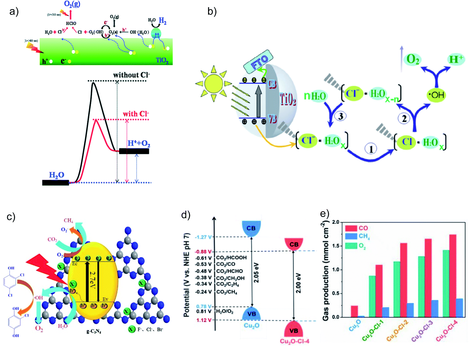 | ||
| Fig. 4 Schematic illustrations of (a) a possible mechanism for how Cl− lowers the water oxidation activation energy on a Cl− adsorbed TiO2 surface. Reprinted with permission from ref. 24. Copyright 2014, Royal Society of Chemistry. (b) Photogenerated hole transfer and reaction pathway with water on Cl-modified rutile TiO2. Reprinted with permission from ref. 25. Copyright 2016, Springer Nature. (c) Photogenerated charge process over halogen-modified g-C3N4. Reprinted with permission from ref. 27. Copyright 2017, Elsevier. (d) Band structure alignments of pure Cu2O and Cu2O–Cl-4. Reprinted with permission from ref. 28. Copyright 2019, Elsevier. (e) Photocatalytic CO2 reduction performance over pure Cu2O and Cl-doped Cu2O samples under 6 h visible-light irradiation. Reprinted with permission from ref. 28. Copyright 2019, Elsevier. | ||
2.2 Oxidation cocatalysts
Cocatalysts usually help lower the activation energy of catalytic reactions, extract/trap superfluous photogenerated carriers to inhibit recombination, and provide active sites for the redox reactions.11 In this case, both reduction cocatalysts for electron capture and oxidation cocatalysts for hole capture have been developed (Fig. 5). Many efforts have been devoted to developing reduction cocatalysts for the photocatalytic CO2RR including various metals (Pt, Ag, Au, etc.), semiconductors (Cu2O, MoS2, etc.) and carbonaceous materials (Fig. 5), while much less attention has been paid to oxidation cocatalysts. In essence, the photogenerated holes usually suffer from low oxidation ability, especially for catalysts with relatively high VB positions. Since oxidation cocatalysts can help lower the activation energy and promote hole trapping, it is desirable to develop oxidation cocatalysts for efficient oxidation reactions accompanying the CO2RR.29–32 So far, some oxidation cocatalysts, such as CoOx, MnOx, RuOx, IrOx and CoPi, have been applied to CO2RR systems, and they exhibit high performance in promoting the oxidation reactions.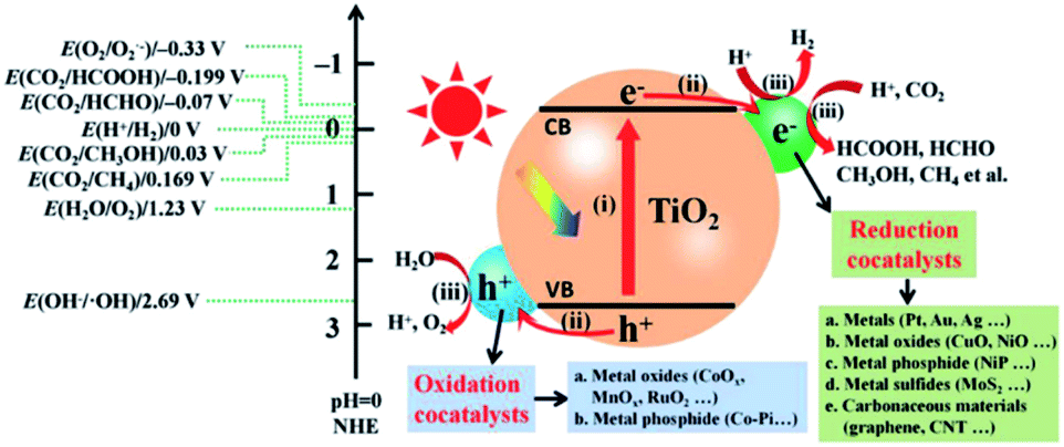 | ||
| Fig. 5 Photocatalytic CO2 reduction over TiO2 loaded with reduction and oxidation cocatalysts (potentials in the plot at pH = 0 vs. NHE). Reprinted with permission from ref. 11. Copyright 2019, Wiley-VCH. | ||
There are some materials that possess the required reduction power for the CO2RR, but the VB position is not positive enough or the overpotential is not large enough to drive the OHR efficiently. In this case, the adoption of oxidation cocatalysts can be helpful. For example, CoOx particles incorporated on g-C3N4 act as an effective oxidative promoter to accelerate the charge transfer kinetics and thus enhance the CO2 to CO conversion.37 Similarly, the introduction of polyoxometalates (Co4) onto g-C3N4 not only facilitates the charge transfer but also increases the surface catalytic oxidative ability of the system, giving rise to high CO yield.38
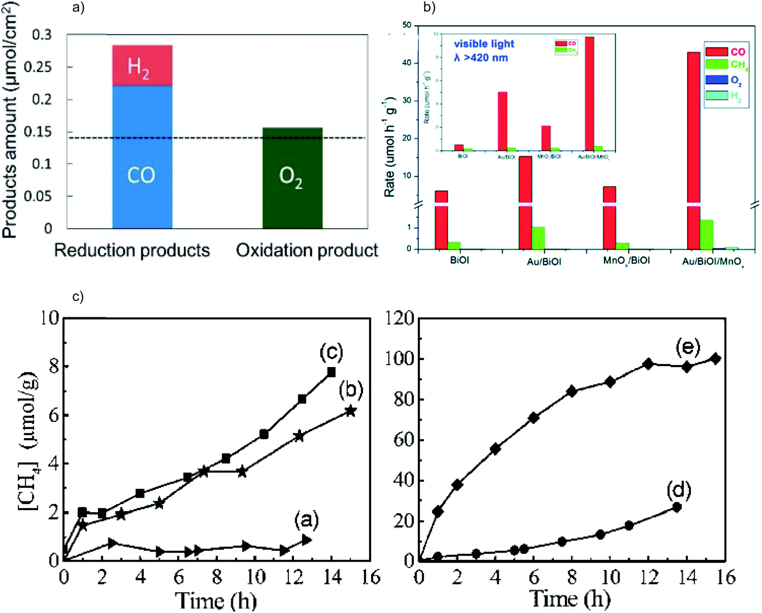 | ||
| Fig. 6 (a) Product yield of photocatalytic CO2 reduction over CuxO/SrTiO3/CoPi. Reprinted with permission from ref. 39. Copyright 2017, American Chemical Society. (b) Photocatalytic CO2RR performance of BiOI, Au/BiOI/MnOx, Au/BiOI and MnOx/BiOI under Xe lamp irradiation; the inset shows the results under visible light irradiation. Reprinted with permission from ref. 40. Copyright 2016, Royal Society of Chemistry. (c) Photocatalytic CO2RR performance of (a) bulk Zn2GeO2, (b) Zn2GeO2 nanoribbons, (c) Pt/Zn2GeO2 nanoribbons, (d) RuO2/Zn2GeO2 nanoribbons and (e) Pt/Zn2GeO2 nanoribbons/RuO2. Reprinted with permission from ref. 41. Copyright 2010, American Chemical Society. | ||
Although the parallel utilization of oxidation and reduction cocatalysts is favorable for the CO2RR, their random distribution may lead to contact between them, giving rise to increased chances of charge recombination and reverse reactions and thus lowered overall efficiency. Accordingly, researchers started to consider designing photocatalysts with a well-defined structure (facet, morphology, etc.) and carefully tuning the loading sites of the reduction and oxidation cocatalysts on the materials.
Hierarchical structures are useful in separating the spatial location of dual cocatalysts. The core–shell structure is the most frequently employed structure among them. For example, TiO2/In2O3 mesoporous hollow spheres with Pt and MnOx loaded on the inner and outer surfaces show high activity for water oxidation because of the opposite flow direction of photogenerated electrons and holes driven by the respective cocatalyst.44 Similarly, TiO2 hollow spheres decorated with spatially separated MnOx and CuPt (Fig. 7a) exhibit a high CO yield of 84.2 μmol g−1 h−1.45 Furthermore, it is also possible to separate the locations of the dual cocatalysts in a 3D porous structure. TiO2–SiO2 with spatially separated CoOx and Pt on the inner and outer surfaces of the skeleton (Fig. 7b) shows a good CH4 production rate and selectivity for the photocatalytic CO2RR in water vapor, which is higher than that of TiO2–SiO2 decorated with randomly scattered CoOx and Pt (Fig. 7c).46
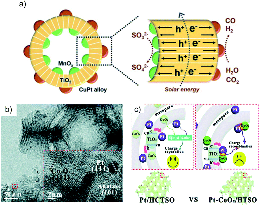 | ||
| Fig. 7 (a) Schematic of MnOx@TiO2@CuPt alloy mesoporous hollow spheres and the charge behavior. Reprinted with permission from ref. 45. Copyright 2018, Royal Society of Chemistry. (b) TEM image of 2%Pt/TiO2–SiO2/CoOx; the inset is the HRTEM image of the red square in the TEM image. Reprinted with permission from ref. 46. Copyright 2016, Royal Society of Chemistry. (c) Comparison of the charge transfer route in the TiO2–SiO2 with separated Pt–CoOx locations (Pt/HCTSO) and random Pt–CoOx locations (Pt–CoOx/HTSO). Reprinted with permission from ref. 46. Copyright 2016, Royal Society of Chemistry. | ||
Photocatalysts with different exposed crystal facets are interesting because it is possible to separate reduction and oxidation locations on a single crystal. A facet heterojunction can be established to drive the photogenerated electrons and holes to migrate toward the respective facet owing to the different work functions of different facets. The reduction and oxidation cocatalysts can be synthesized on the corresponding facets to trap the respective charge carriers so as to further increase the charge separation efficiency. TiO2 is a typical semiconductor that can be prepared with a co-exposed hole-rich {001} facet and electron-rich {101} facet to form the facet heterojunction. The oxidation and reduction cocatalysts are selectively deposited on the corresponding facet to trap the electrons and holes, respectively. Ag/TiO2{101}/TiO2{001}/MnOx47,48 and Pt/TiO2{101}/TiO2{001}/MnOx49 have been demonstrated to be efficient systems for the photocatalytic CO2RR. Taking the Pt/TiO2{101}/TiO2{001}/MnOx system as an example, Pt and MnOx are selectively deposited on the respective facets of TiO2{101} and {001} (Fig. 8a–d). TiO2 with the dual cocatalysts shows enhanced photocatalytic CO2RR performance (Fig. 8e) due to the efficient carrier migration induced by the facet junction and joint electron–hole extraction by the cocatalysts (Fig. 8f).
 | ||
| Fig. 8 (a–d) SEM images and (e) photocatalytic CO2RR performance of TiO2 (T), TiO2/MnOx (TM), TiO2/Pt (TP) and TiO2/MnOx/Pt (TMP), (f) schematic diagram of the photocatalytic CO2RR mechanism of TiO2/MnOx/Pt. Reprinted with permission from ref. 49. Copyright 2019, American Chemical Society. | ||
2.3 Z-Scheme structures
Combining different semiconductors to form a heterostructure offers a feasible way to realize the photocatalysis with a tunable light response, efficient charge separation, prolonged charge carrier lifetime, and long-term stability of the photocatalysts. Typically, two types of heterostructures are most frequently used for photocatalysis, type II and Z-scheme systems. The type II heterojunction is a classical structure with enhanced catalytic performance compared to the single semiconductor, due to an extended light response and efficient spatial charge separation via the favorable staggered band alignment. However, in the type II structure the CO2RR and OHR are respectively driven by charges with weakened reduction and oxidation power (Fig. 9a). The Z-scheme heterostructure stands out as a more efficient “artificial photosynthesis” system than the type II heterojunction, which exhibits stronger redox capability by simultaneously retaining the electrons and holes in the respective higher levels of the VB and CB (Fig. 9b). Generally, in a Z-scheme system the holes with less positive oxidation potentials recombine with the electrons with less negative reduction potentials, and thus the high redox power can be maintained. Therefore, Z-scheme systems usually deliver higher photocatalytic performance than their single material counterparts, due to long carrier lifetime, no energy loss, and high stability owing to the timely consumption of photogenerated charge carriers. Since the Z-scheme systems for the photocatalytic CO2RR have been systematically summarized recently,12 here we just discuss some of them to demonstrate the importance of the Z-scheme in boosting the OHR and thus enhancing the CO2RR performance.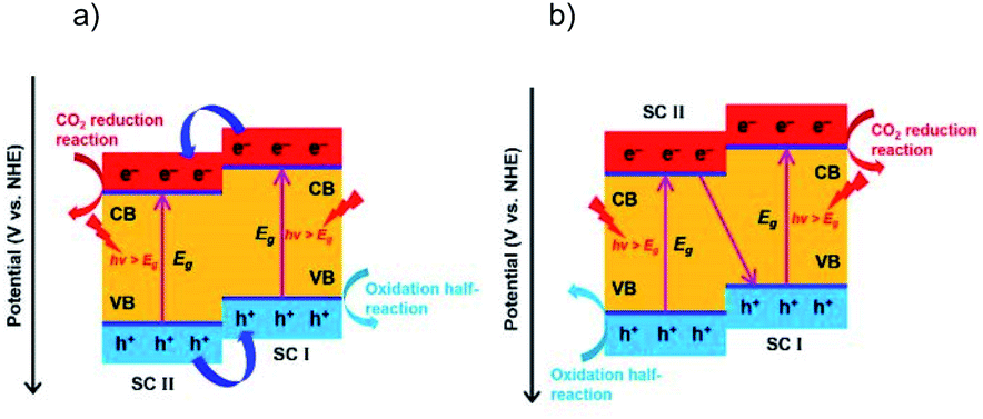 | ||
| Fig. 9 Photocatalytic CO2 reduction on (a) a type II heterojunction, and (b) Z-scheme system. Reprinted with permission from ref. 12. Copyright 2020, Wiley-VCH. | ||
In a Z-scheme photocatalytic system, one semiconductor has a high CB position and another has a low VB position, making it possible to couple the CO2RR active semiconductor with that usually active in the OHR. Thus, many Z-scheme systems can be used to photoreduce CO2 in aqueous solution. The common Z-scheme systems include indirect and direct ones. In an indirect Z-scheme system, there is a redox mediator such as Fe3+/Fe2+ or IO3−/I− or an electron bridge like a noble metal or RGO, while a direct Z-scheme system consists of two semiconductors in direct contact.
g-C3N4/Bi4O5I2 with I3−/I− as the redox mediator is an efficient system for the photocatalytic CO2RR in H2O.50 CO is found to be the major reduction product with an optimized yield 7.9 and 2.3 times higher than that using pure g-C3N4 and Bi4O5I2, respectively (Fig. 10a). Interestingly, O2 is produced as the oxidation product over g-C3N4/Bi4O5I2 and pure C3N4, while no O2 is observed over Bi4O5I2. This phenomenon indicates that the high oxidation capability is preserved in C3N4/Bi4O5I2, which has also been confirmed via hydroxyl radical (˙OH) quantification experiments (Fig. 10b). Another example is all-solid-state Z-scheme systems with Au in between two semiconductors as the electron bridge. WO3 is usually used as the oxidation photocatalyst, with high oxidation power but no CO2 reduction capability. The Z-scheme charge transfer mode is realized between WO3 and semiconductors with a high CB position for enhanced photocatalytic CO2RR, such as CdS,51 Cu2O52 and In2S3.53 For instance, WO3 is coupled with In2S3, which exhibits a high enough reduction power for the CO2RR, to construct the WO3/Au/In2S3 Z-scheme system.53 The results of Kelvin probe force microscopy (KPFM) indicate that the surface potential of WO3/Au/In2S3 is much higher than that of pure WO3 and WO3/In2S3, demonstrating the highest number of photogenerated holes accumulated in WO3/Au/In2S3 (Fig. 11a). This work clearly indicates that the Z-scheme charge transfer is effective in promoting the high oxidation ability of WO3 and thereby extracting more electrons from In2S3 for the CO2RR (Fig. 11b).
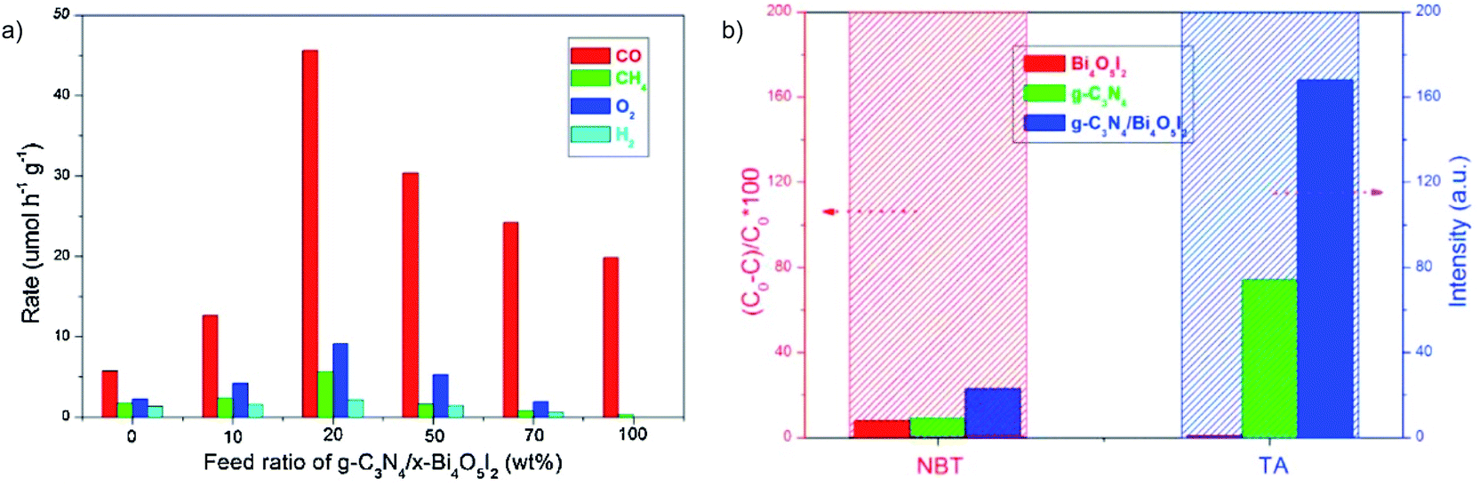 | ||
| Fig. 10 (a) Photocatalytic CO2RR rate for g-C3N4/x-Bi4O5I2 (x = 0, 10, 20, 50, 70 and 100), and (b) reactive oxygen species quantification experiments: TA represents ˙OH. Reprinted with permission from ref. 50. Copyright 2016, Elsevier. | ||
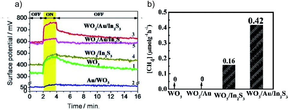 | ||
| Fig. 11 (a) Surface potential of samples under test (1–4 and 5 under λ = 410 and 550 nm illumination), and (b) photocatalytic CO2RR results over different samples. Reprinted with permission from ref. 53. Copyright 2016, American Chemical Society. | ||
Similar results are obtained over the CoZnAl-LDH/RGO/g-C3N4 Z-scheme, which has superior activity for both reduction and oxidation in selective conversion of CO2 to CO and methylene blue degradation, respectively.54 Recently, the common oxidation semiconductor α-Fe2O3 was combined with CsPbBr3, using amine functionalized RGO as an efficient mediator to regulate the interfacial interactions (Fig. 12a–d). Such α-Fe2O3/amine-RGO/CsPbBr3 Z-scheme system makes it possible to take advantage of the high reduction power of CsPbBr3 for the CO2RR and high oxidation power of α-Fe2O3 for the OER, resulting in significantly higher activity for the CO2RR than that using CsPbBr3 and α-Fe2O3/CsPbBr3 with almost stoichiometric O2 production (Fig. 12e).55 Control experiments have confirmed that the sources of reduction and oxidation products are CO2 and H2O, respectively.
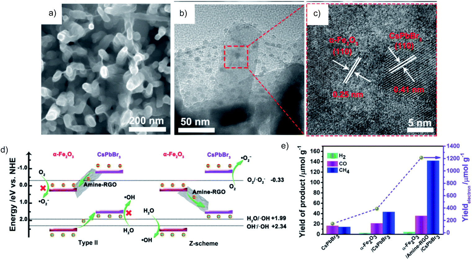 | ||
| Fig. 12 a) SEM, (b) TEM and (c) HRTEM images of α-Fe2O3/amine-RGO/CsPbBr3, (d) energy band diagram and the reaction mechanism in type II and Z-scheme heterojunctions (pH = 0), and (e) photocatalytic CO2RR performance after 15 h. Reprinted with permission from ref. 55. Copyright 2020, Elsevier. | ||
The direct Z-scheme system consisting of two semiconductors is more easily achieved considering the preparation simplicity. It is to be noted that it is always necessary to verify the charge carrier migration path to differentiate it from the type II heterojunction. Although CdS/Au/TiO2 is an efficient Z-scheme system,56 it is also possible to directly construct an interface between CdS and TiO2 that follows the Z-scheme charge transfer mechanism. For example, Low et al. reported a direct Z-scheme TiO2/CdS film.57 Both in situ irradiated X-ray photoelectron spectroscopy (ISI-XPS) and photoluminescence (PL) spectroscopy are used to prove the Z-scheme charge migration in TiO2/CdS that exhibits much higher performance for the photocatalytic CO2RR in H2O, compared to that of pure CdS, TiO2 and commercial P25 (Fig. 13a). The binding energy of Ti 2p and Cd 3d respectively shows a blue and a red shift under illumination compared to that without illumination, corresponding respectively to decreased and increased electron density under illumination (Fig. 13b and c). Moreover, probing the oxidation capability is another means to study the Z-scheme transfer path. With the help of a probe molecule for ˙OH detection, the PL spectrum results indicate significantly enhanced production of oxidative ˙OH in TiO2/CdS, but a very low PL signal for CdS due to its less positive VB potential for ˙OH radical generation (Fig. 13d). Thus, the holes accumulated in this composite come from Z-scheme transfer rather than the type II mode (Fig. 13e and f). Another structure, InVO4/β-AgVO3, is also proved by ISI-XPS to be an effective Z-scheme system for the photocatalytic CO2RR with O2 as the oxidation product from H2O. The carbon source of the reduction products and oxygen source of the obtained O2 was confirmed by isotopically labelled 13CO2 and H218O, respectively.58
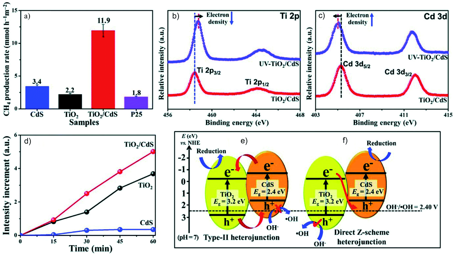 | ||
| Fig. 13 (a) The photocatalytic CO2RR over CdS, TiO2, TiO2/CdS and P25, high resolution XPS spectra of (b) Ti 2p and (c) Cd 3d under irradiation, (d) PL intensity of 7-hydroxycoumarin over CdS, TiO2 and TiO2/CdS under illumination, and comparison of the charge carrier migration paths following (e) type II and (f) Z-scheme mechanisms for TiO2/CdS. Reprinted with permission from ref. 57. Copyright 2018, Wiley-VCH. | ||
3D-SiC@2D-MoS2 is another efficient direct Z-scheme system for simultaneous photocatalytic CO2 reduction to CH4 and H2O oxidation to O2.59 The high performance is not only due to the Z-scheme charge separation, but also the high hole mobility of MoS2 and electron mobility of SiC that respectively accelerate the water oxidation and CO2 reduction, with 18O and 13C tracer experiments confirming the product origin.
Apart from the favorable charge separation and driving force, the Z-scheme system is also effective in improving the photocatalyst stability. Among the semiconductors active for the CO2RR, the narrow bandgap ones that possess high reduction power usually undergo self-oxidation by the photogenerated holes and rapid charge recombination, such as metal sulfides and Cu2O. The Z-scheme mechanism provides a recombination drive-thru for the photogenerated charge carriers with inferior redox potentials, resulting in fast consumption of the holes and accordingly protecting the photocatalyst. The stability of Cu2O is enhanced by constructing a Z-scheme system with TiO2, and the obtained Cu2O/TiO2 showed a 4 times higher production rate of CO than pure Cu2O.60 CuGaS2/RGO/TiO2 is another efficient and stable Z-scheme system for the photocatalytic CO2RR, with a stoichiometric ratio of O2 and reduction products.61
Besides the systems mentioned in Sections 2.1, 2.2 and 2.3, other strategies have also been considered to tune the hole behavior. For instance, the formation of a Schottky junction between Au and a p-GaN photocathode can favor the collection of plasmon-induced hot holes with strong oxidation power, resulting in enhanced activity and selectivity of CO production from photoelectrochemical CO2 reduction in aqueous electrolyte.62
Despite the remarkable progress in tuning hole behavior through photocatalyst design like doping, loading cocatalysts and establishing Z-scheme structures, there are still obstacles that remain to be overcome. For example, compared to the large number of reductive semiconductors and cocatalysts for the CO2RR, only a few oxidative candidates are available to construct effective Z-scheme or semiconductor/cocatalyst systems. Moreover, the activity of oxidation cocatalysts is still not equivalent to that of the reduction cocatalysts, which needs further study to balance the reduction and oxidation performance.2 In addition, the contact between different materials in a composite photocatalyst is always important for efficient electron–hole transfer. Thus, special attention should also be paid to the rational design of the interface between semiconductors and/or cocatalysts and deliberate consideration of the lattice mismatch, as well as an in-depth understanding of the structure–property relationship.
3 Electron donors
To prevent the accumulation of holes on the photocatalyst surface and to facilitate the charge separation and CO2RR as well, electron donors are essential for donating electrons and protons during the reactions. Generally, electron donors exhibit different donating properties, and range from strong donors like triethanolamine (TEOA) to weak donors like H2O. The CO2RR is an uphill reaction (ΔGθ > 0) when H2O serves as the electron donor, making the overall reaction “nonsacrificial”, while the adoption of a strong electron donor can make the overall reaction “sacrificial” (ΔGθ < 0).633.1 H2O
H2O is the most frequently adopted electron donor for CO2 conversion to value-added chemicals since it provides a “green chemistry” route, given that no external sacrificial reagents are consumed.64 Ideally, the reaction between H2O and holes can generate O2 or H2O2, as well as protons that can also participate in the CO2RR.65In terms of standard electrode potentials of the reduction and oxidation half reactions, one can deduce the minimum driving force for the CO2RR in H2O (eqn (1)–(5)), where ΔGθ is the free energy and ΔEθ is the standard redox potential.66,67 Taking the conversion of CO2 into CO as an example, it requires a bandgap value of at least 1.33 eV for a photocatalyst to drive this reaction (Eqn (1)).
| CO2 → CO + O2, ΔGθ = 257 kJ mol−1, ΔEθ = 1.33 V | (1) |
| CO2 + H2O → HCOOH + 1/2O2, ΔGθ = 286 kJ mol−1, ΔEθ = 1.48 V | (2) |
| CO2 + H2O → HCHO + O2, ΔGθ = 522 kJ mol−1, ΔEθ = 1.35 V | (3) |
| CO2 + 2H2O → CH3OH + 3/2O2, ΔGθ = 703 kJ mol−1, ΔEθ = 1.21 V | (4) |
| CO2 + 2H2O → CH4 + 2O2, ΔGθ = 818 kJ mol−1, ΔEθ = 1.06 V | (5) |
It seems that the bandgap requirement is not very harsh. However, considering that the power of both electrons and holes should respectively meet the CO2RR and OER potential, and an overpotential is usually required, suitable semiconductors for the CO2RR in H2O usually have a wide bandgap. Pioneering work for the photocatalytic CO2RR in H2O was reported in 1979, in which several photocatalysts (including TiO2, ZnO, CdS, GaP and SiC) were used to reduce CO2 to organic compounds in H2O.68 Substantial efforts have been devoted thereafter to photocatalysts for the CO2RR with H2O as the electron donor, including the aforementioned TiO2,69,70 and other materials like K2Ti6O13,71 BiOCl,72 Mg–In layered double hydroxides73 and g-C3N4.74
The efficiency for photocatalytic CO2 reduction with H2O has been unsatisfactory hitherto, making it difficult to reproduce reliable results. Moreover, even though it is well accepted that the CO2RR is accompanied by the OER from the water oxidation, the activity is often evaluated only by the CO2RR product yield. In many cases, the evolution of O2 is not observed or reported, leading to vagueness in the consumption of photogenerated holes or the stability of the semiconductors, since holes can be consumed by either the electron donors, photocatalysts, or residual carbon species. In this respect, the study of the OER is necessary and evidence is required to demonstrate that the produced O2 is generated from H2O oxidation. The isotope tracer experiment using H218O as the reagent is one method to verify that H2O is the oxygen source.75,76 Another method is to calculate the ratio of reacted electrons to holes, which should be unity to indicate that H2O is the sole electron donor (i.e. e−/h+ = 1).77
Stoichiometric chemistry is always a challenge for the CO2RR in H2O, even though overall H2O splitting has been widely proved to be feasible in which O2 and H2 are evolved simultaneously. It is difficult to ideally couple the CO2RR with H2O oxidation since it requires high reduction and oxidation power for the photogenerated charge carriers to drive the two half reactions, and there is a competitive H2O reduction as well.
So far most of the research has only focused on characterizing the reduction products. The O2 amount is disregarded in most cases, or no stoichiometric ratio of the reduction products/O2 is reached. The first report on the CO2 photoconversion accompanied by the OER dates back to 1992 over the CeO2/TiO2 composite.78 So far, only a limited number of materials have clearly been demonstrated to be capable of producing O2 as the oxidation product. Table 1 shows those that can realize the photocatalytic CO2RR in H2O with simultaneous production of O2 and CO2RR products.
| No. | Photocatalyst | Weight/g | Bandgap/eV | Reduction productsa | Oxidation products (O2)a | e−/h+b | Conditions (solution & illumination) | Ref. |
|---|---|---|---|---|---|---|---|---|
| Unit is μmol g h−1 unless otherwise noted | Unit is μmol g h−1 unless otherwise noted | |||||||
| a The amount of reduction and oxidation products is converted to the same unit by processing the original data, which are just used for reference. It is meaningless to directly compare them, as the experimental conditions can be quite different among them, such as the catalyst amount, electrolyte, illumination source and reaction time, all of which have a strong impact on evaluating the photocatalysts. b e−/h+ = (number of electrons consumed for reduction products)/(number of holes consumed for O2 formation). c ‘—’ means that the corresponding data are not mentioned in the related reference. | ||||||||
| 1 | 1.0 wt% Cu/ZrO2 | 1.0 | 5.0 | CO: 2.5 ± 0.1, H2: 19.5 ± 0.3 | 10.8 ± 0.2 | 1.02 | NaHCO3 aqueous solution, 400 W high-pressure Hg lamp | (1993)101 |
| 2 | 2.0 wt% Ag/BaLa4Ti4O15 | 0.3 | 3.9 | CO: 73.33, HCOOH: 2.33, H2: 33.33 | 53.33 | 1.02 | H2O, 400 W high-pressure mercury lamp | (2011)79 |
| 3 | 1.0 wt% Ag/La2Ti2O7 | 1.0 | 4.05 | CO: 5.2, H2: 4.9 | 5.3 | 0.95 | H2O, 400 W high-pressure mercury lamp | (2015)102 |
| 4 | 0.5 wt% Ag/CaTiO3 | 0.2 | 3.6 | CO: 1.75, H2: 2.15 | 1.8 | 1.08 | NaHCO3 aqueous solution (1.1 mol L−1), 300 W xenon lamp | (2015)103 |
| 5 | 3.5 wt%Ag/CaTiO3 | 0.3 | 3.6 | CO: 180, H2: 10.33 | 83.33 | 1.14 | NaHCO3 aqueous solution (1 mol L−1), 100 W high pressure mercury lamp | (2017)104 |
| 6 | 1.0 wt% Ag/4 mol% Al–SrTiO3 | 0.5 | — | CO: 14.4, H2: 0.3 | 7.16 | 1.03 | NaHCO3 aqueous solution (0.1 mol L−1), 400 W high-pressure Hg lamp (λ > 300 nm) | (2020)19 |
| 7 | 0.5 wt% Ag/SrNb2O6 nanorods | 0.5 | 3.86 | CO: 102.4, H2: 2.2 | 49.6 | 1.05 | NaHCO3 aqueous solution (0.1 mol L−1), 400 W high-pressure Hg lamp | (2017)105 |
| 8 | KTaO3 | 0.1 | 3.7 | CO: 61.98 ppm g−1 h−1, H2: 1323.00 ppm g−1 h−1 | 501.87 ppm g−1 h−1 | 1.38 | H2O, 300 W xenon arc lamp | (2014)106 |
| 9 | 0.5 wt% Ag/KCaSrTa5O15 | 0.5 | 4.1 | CO: 16.2, H2: 112 | 74 | 0.83 | H2O, 400 W high-pressure mercury lamp | (2014)80 |
| 10 | 0.5 wt% Ag/KCaSrTa5O15 | 0.5 | 4.12 | CO: 194, H2: 30 | 92 | 1.22 | NaHCO3 aqueous solution (0.1 mol L−1), 400 W high-pressure mercury lamp | (2015)81 |
| 11 | (a) 2.0 wt% Ag/NaTaO3:Ca (5.0%) | 0.25–0.5 | 4.1 | (a) CO: 394.67, H2: 40 | (a) 224 | (a) 0.97 | H2O, 400 W high-pressure Hg lamp | (2017)82 |
| (b) 2 wt% Ag/NaTaO3:Sr (5%) | (b) CO: 469.33, H2: 74.67 | (b) 272 | (b) 1.00 | |||||
| (c) 3.0 wt% Ag/NaTaO3:Ba (5.0%) | (c) CO: 333.33, H2: 64 (0.375 g for calculation) | (c) 202.67 | (c) 0.98 | |||||
| 12 | 3.0 wt% Ag/ZnTa2O6 | 0.5 | 4.5 | CO: 38.6, H2: 50.2 | 37.2 | 1.19 | NaHCO3 aqueous solution (0.1 mol L−1), 400 W high-pressure Hg lamp | (2016)107 |
| 13 | Ag/SrO/Ta2O5 | 1.0 | — | CO: 6.8, H2: 3.8 | 5.1 | 1.04 | NaHCO3 aqueous solution (0.1 mol L−1), 400 W high-pressure mercury lamp | (2015)108 |
| 14 | 1.0 wt% Ag–Sr2KTa5O15 | 1.0 | 4.0 | CO: 65.5, H2: 8 | 35 | 1.05 | NaHCO3 aqueous solution (0.1 mol L−1), 400 W high-pressure mercury lamp | (2016)109 |
| 15 | 1.0 wt% Ag/Sr1.6K0.37Na1.43Ta5O15 | 1.0 | 3.95 | CO: 94.6, H2: 16 | 53.8 | 1.03 | NaHCO3 aqueous solution (0.1 mol L−1), 400 W high-pressure mercury lamp | (2017)110 |
| 16 | 1.0 wt% Ag/K2YTa5O15 | 1.0 | 3.86 | CO: 91.9, H2: 16.3 | 43.2 | 1.25 | NaHCO3 aqueous solution (0.1 mol L−1), 400 W high-pressure mercury lamp | (2018)111 |
| 17 | 0.1 wt% Ag/Ga2O3 | 0.2 | 4.1 | CO: 10, H2: 47 | 23 | 1.24 | NaHCO3 aqueous solution (1 mol L−1), 300 W xenon lamp | (2015)112 |
| 18 | Ag/Zn-Doped Ga2O3 | 1.0 | — | CO: 117.0, H2: 16.9 | 70.1 | 0.96 | NaHCO3 aqueous solution (0.1 mol L−1), 400 W high-pressure mercury lamp | (2014)113 |
| 19 | 1.0 wt% Ag/Ga2O3 with a (3.0 mol%) ZnGa2O4 layer | 1.0 | Ga2O3: 4.6, ZnGa2O4: 4.2 | CO: 108, H2: 8.9 | 60.6 | 0.96 | NaHCO3 aqueous solution (0.1 mol L−1), 400 W high-pressure mercury lamp | (2016)114 |
| 20 | Ag/3.0 mol% Yb-3.0 mol% Zn/Ga2O3 | 0.5 | 4.68 | CO: 300, H2: 75.2 | 206 | 0.91 | NaHCO3 aqueous solution (0.1 mol L−1), 400 W Hg lamp | (2017)115 |
| 21 | Ag/3.0 mol% Pr/Ga2O3 | 0.5 | — | CO: 498, H2: 129.4 | 300.8 | 1.04 | NaHCO3 aqueous solution (0.1 mol L−1), 400 W high-pressure mercury lamp | (2017)116 |
| 22 | 0.25 wt% Ag/95-MgAl LDH/Ga2O3 | 1.0 | — | CO: 211.7, H2: 130 | 169 | 1.01 | NaHCO3 aqueous solution (0.1 mol L−1), 400 W high-pressure mercury lamp | (2017)117 |
| 23 | 1.0 mol% Ag-1.0 mol% Cr/Ga2O3 | 0.5 | — | CO: 960, H2: 185.8 | 562 | 1.02 | NaHCO3 aqueous solution (0.1 mol L−1), 400 W high-pressure mercury lamp | (2018)118 |
| 24 | 0.25 mol% Ag@Cr/Ga2O3 | 0.5 | — | CO: 1050.6, H2: 180 | 650 | 0.95 | NaHCO3 aqueous solution (0.1 mol L−1), 400 W high-pressure mercury lamp | (2018)119 |
| 25 | Ag–Cr/Ga2O3:Rh (0.7 mol%) | 0.5 | Ga2O3: 4.7, Ga2O3:Rh: 3.6 & 2.9 | CO: 7.8, H2: 20.6 | 13 | 1.09 | NaHCO3 aqueous solution (0.1 mol L−1), 400 W high-pressure mercury lamp (λ > 300 nm) | (2018)120 |
| 26 | ZnGa2O4 nanocubes | 0.1 | 4.4 | CH4: 1.6 | 12.0 | 0.27 | H2O vapor, UV-enhanced (200 to 350 nm) 300 W xenon arc lamp | (2013)7 |
| 27 | 1.0 wt% Ag/ZnGa2O4 | 1.0 | 4.67 | CO: 155, H2: 8.5 | 74.3 | 1.10 | NaHCO3 aqueous solution (0.1 mol L−1), 400 W high-pressure mercury lamp | (2015)121 |
| 28 | Mg–In LDH | 0.1 | —c | CO: 3.21 | 17 | 0.09 | H2O, 200 W Hg–Xe lamp | (2012)73 |
| 29 | Bi2O2(OH) (NO3)–Br | 0.02 | 3.15 | CO: 6.5 | 3.0 | 1.08 | H2O vapor, 300 W xenon lamp | (2019)122 |
| 30 | InVO4 sheets | 0.1 | 2.3 | CO: 18.3, CH4: 0.3 | 8.5 | 1.14 | H2O vapor, xenon lamp | (2019)85 |
| 31 | InVO4/β-AgVO3 | 0.05 | β-AgVO3: 2.15, InVO4: 2.36 | CO: 12.61, H2: 0.13 | 5400 | 0.0012 | H2O vapor, 300 W xenon lamp (λ > 420 nm) | (2019)58 |
| 32 | WO3 | — | 2.36 | CO: 2.8 | 1.7 | 0.85 | H2O, 40 W silicon nitride lamp (0.8 to 17 μm) | (2018)86 |
| 33 | WO3/Au/In2S3 | 10 cm2 | CH4: 0.42 | 0.86 | 0.98 | H2O vapor, 300 W xenon arc lamp (λ > 420 nm) | (2016)53 | |
| 34 | Hollow multi-shelled structures of Co3O4 dodecahedron | 0.005 | 2.33 | CO: 46.3 | 22 | 1.05 | H2O vapor, 200 W Xe lamp with a standard AM 1.5 filter and a 780 nm reflector | (2019)123 |
| 35 | CoN | — | 1.44 | CO: 0.29 | 0.15 | 0.97 | H2O, xenon lamp (λ > 800 nm) | (2020)87 |
| 36 | Mg2(DOBDC)/TiO2, DOBDC = 2,5-dioxido-1,4-benzenedicarboxylate | 0.01 | — | CO: 4.1, CH4: 2.4 | 6.3 | 1.07 | H2O vapor, four 4 W UV lamps with a wavelength centered at 365 nm | (2016)88 |
| 37 | TTCOF–Zn | 0.01 | 1.49 | CO: 2.06 | 0.98 | 1.05 | H2O, 300 W xenon lamp (λ = 420–800 nm) | (2019)89 |
| 38 | BiOI/g-C3N4 | 0.1 | BiOI: 1.75, g-C3N4: 2.69 | CO: 4.86, CH4: 0.18 | 0.78 | 3.58 | H2O vapor, 300 W xenon arc lamp (λ > 400 nm) | (2016)65 |
| 39 | Bi4O5I2/g-C3N4 | 0.1 | Bi4O5I2: 1.45, g-C3N4: 2.31 | CO: 45.6, CH4: 6, H2: 2.2 | 9 | 3.99 | H2O vapor, 300 W xenon lamp (λ > 400 nm) | (2016)50 |
| 40 | Bi2WO6/RGO/g-C3N4 | 0.05 | g-C3N4: 2.65, Bi2WO6: 2.82 | CO: 16, CH4: 2.5, H2: 2.25 | 10.5 | 1.35 | H2O vapor, 300 W xenon arc lamp (λ > 420 nm) | (2018)124 |
| 41 | Nb–TiO2/g-C3N4 | 0.1 | Nb–TiO2: 2.91, g-C3N4: 2.68 | CH4: 562, CO: 420, HCOOH: 698 | 1702 | 0.99 | H2O vapor, two 30W white bulbs | (2019)125 |
| 42 | CuGaS2/RGO/TiO2 | 0.1 | CuGaS2: 2.3 | CO: 1.5, H2: 288 | 112 | 1.29 | H2O, 300 W xenon lamp (λ > 330 nm) | (2017)61 |
| 43 | Cl-Doped Cu2O nanorods | — | Cu2O–Cl-4: 2 | CO: 1.74 μmol cm−2, CH4: 0.39 μmol cm−2 | 1.41 μmol cm−2 | 1.17 | H2O vapor, 350 W xenon lamp (λ > 420 nm) | (2019)28 |
| 44 | CuxO/SrTiO3/CoPi | — | SrTiO3: 3.2 | CO: 0.225 μmol cm−2, H2: 0.06 μmol cm−2 | 0.155 μmol cm−2 | 0.92 | Aqueous solution containing KHCO3 (0.5 mol L−1), KH2PO4 (0.025 mol L−1), and K2HPO4 (0.025 mol L−1), Hg- xenon lamp (UV light irradiation) | (2017)39 |
| 45 | Cu2O/WO3 | 0.085 | WO3: 2.75, Cu2O: 2.05 | CO: 137.65, H2: 67.06 | 8.24 | 12.4 | H2O vapor, 300 W xenon arc lamp (λ > 400 nm) | (2019)52 |
| 46 | α-Fe2O3/amine-RGO/CsPbBr3 | — | CsPbBr3: 2.36, α-Fe2O3: 2.2 | CH4: 9.45, CO: 2.36, H2: 0.29 | 18.67 | 1.08 | H2O vapor, 150 W xenon lamp (λ > 420 nm) | (2020)55 |
| 47 | Fe2V4O13/RGO/CdS | 0.025 | Fe2V4O13: 1.83, CdS: 2.4 | CH4: 156 | 92 | 3.39 | H2O vapor, 300 W xenon lamp | (2015)126 |
| 48 | SiC@MoS2 | 0.01 | SiC: 2.48, MoS2: 1.77 | CH4: 323 μL g−1 h−1 | 621 μL g−1 h−1 | 1.04 | H2O vapor, 300 W xenon lamp (λ ≥ 420 nm) | (2018)59 |
It is to be noted that Kudo et al. have reported a series of Ag loaded ALa4Ti4O15 (A = Ca, Sr and Ba) photocatalysts with a wide bandgap, showing simultaneous CO2 reduction and H2O oxidation. Specifically, Ag/BaLa4Ti4O15 exhibits selective CO2 reduction over H2O splitting with stoichiometric O2 production (Fig. 14).79 Ag/KCaSrTa5O15 (ref. 80 and 81) and Ag/(Ca, Sr, Ba) doped NaTaO3 (ref. 82) also show good performance for CO2 reduction with the ratio of reacted electrons/holes as unity. Tanaka et al. have developed a bunch of metal oxides modified by Ag or doped with other metals, including Ga2O3, ZnGa2O4, Ta2O5, ZnTa2O6, La2Ti2O7, SrNb2O6, Sr2KTa5O15, K2YTa5O15, layered double hydroxides (LDHs) and SrTiO3, which can realize stoichiometric CO2 reduction and H2O oxidation (see Table 1).
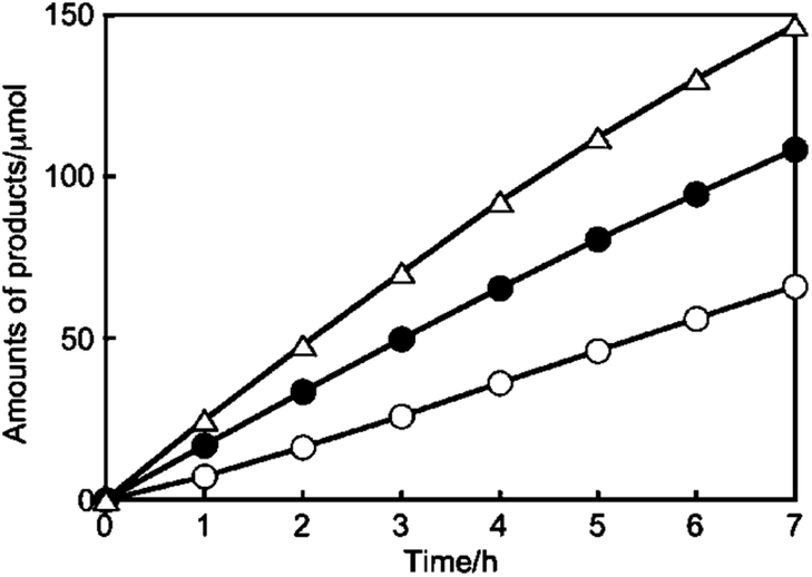 | ||
| Fig. 14 Photocatalytic CO2RR performance over Ag/BaLa4Ti4O15: amounts of H2 (○), O2 (●), and CO (△) produced. Reprinted with permission from ref. 79. Copyright 2011, American Chemical Society. | ||
Even though some materials have been reported to show CO2 reduction activity in H2O, not all of them exhibit higher selectivity for CO2 reduction than H2 evolution, as listed in Table 1. Moreover, most of the materials in Table 1 possess a wide bandgap so as to meet the requirement for reduction and oxidation potentials, while they are only responsive to UV light that accounts for ca. 4% of the total solar energy. Recently, some efforts have been devoted to developing photocatalysts with an extended light-response spectrum. Zou et al. reported simultaneous photocatalytic conversion of CO2 and H2O under visible-light irradiation over ultrathin WO3 nanosheets83 and over Bi2WO6 nanoplates,84 while no O2 evolution information was reported. They also prepared atomically thin InVO4 nanosheets (Eg = 2.3 eV) with highly selective CO2 reduction performance, exhibiting almost stoichiometric CO and CH4 with O2.85 Furthermore, considering that infrared (IR) light occupies around 50% of the solar radiation, IR-activated CO2 reduction in H2O is appealing. Xie et al. reported IR-driven CO2 reduction to CO and O2 over oxygen-deficient WO3 atomic layers with an intermediate band (Fig. 15a–f).86 They also designed metallic CoN porous atomic layers with a narrow bandgap (Eg = 1.44 eV) for CO2 reduction in H2O under IR light illumination, displaying a 2![[thin space (1/6-em)]](https://www.rsc.org/images/entities/char_2009.gif) :1 ratio of CO to O2, but the evolution rate is very low without using sacrificial reagents (CO: 0.29 μmol g−1 h−1, O2: 0.15 μmol g−1 h−1).87 Hence, further development of active photocatalysts with a broadband spectrum response is imperative. Except for the aforementioned photocatalysts, other materials and structures have also shown successful CO2RR and OER, such as lead halide perovskites,75 metal–organic frameworks (entry 36, Table 1)88 and covalent organic frameworks (entry 37, Table 1).89 In order to tune the properties of the photocatalyst system in a more flexible way, heterostructures consisting of different materials are employed (e.g. entries 33, 38, 42, 45, 47 and 48 in Table 1), which can either extend the light response region, favor the charge separation, or meet the requirement for the CO2 reduction and H2O oxidation reaction simultaneously. Some of these systems have been analyzed in detail in Section 2.
:1 ratio of CO to O2, but the evolution rate is very low without using sacrificial reagents (CO: 0.29 μmol g−1 h−1, O2: 0.15 μmol g−1 h−1).87 Hence, further development of active photocatalysts with a broadband spectrum response is imperative. Except for the aforementioned photocatalysts, other materials and structures have also shown successful CO2RR and OER, such as lead halide perovskites,75 metal–organic frameworks (entry 36, Table 1)88 and covalent organic frameworks (entry 37, Table 1).89 In order to tune the properties of the photocatalyst system in a more flexible way, heterostructures consisting of different materials are employed (e.g. entries 33, 38, 42, 45, 47 and 48 in Table 1), which can either extend the light response region, favor the charge separation, or meet the requirement for the CO2 reduction and H2O oxidation reaction simultaneously. Some of these systems have been analyzed in detail in Section 2.
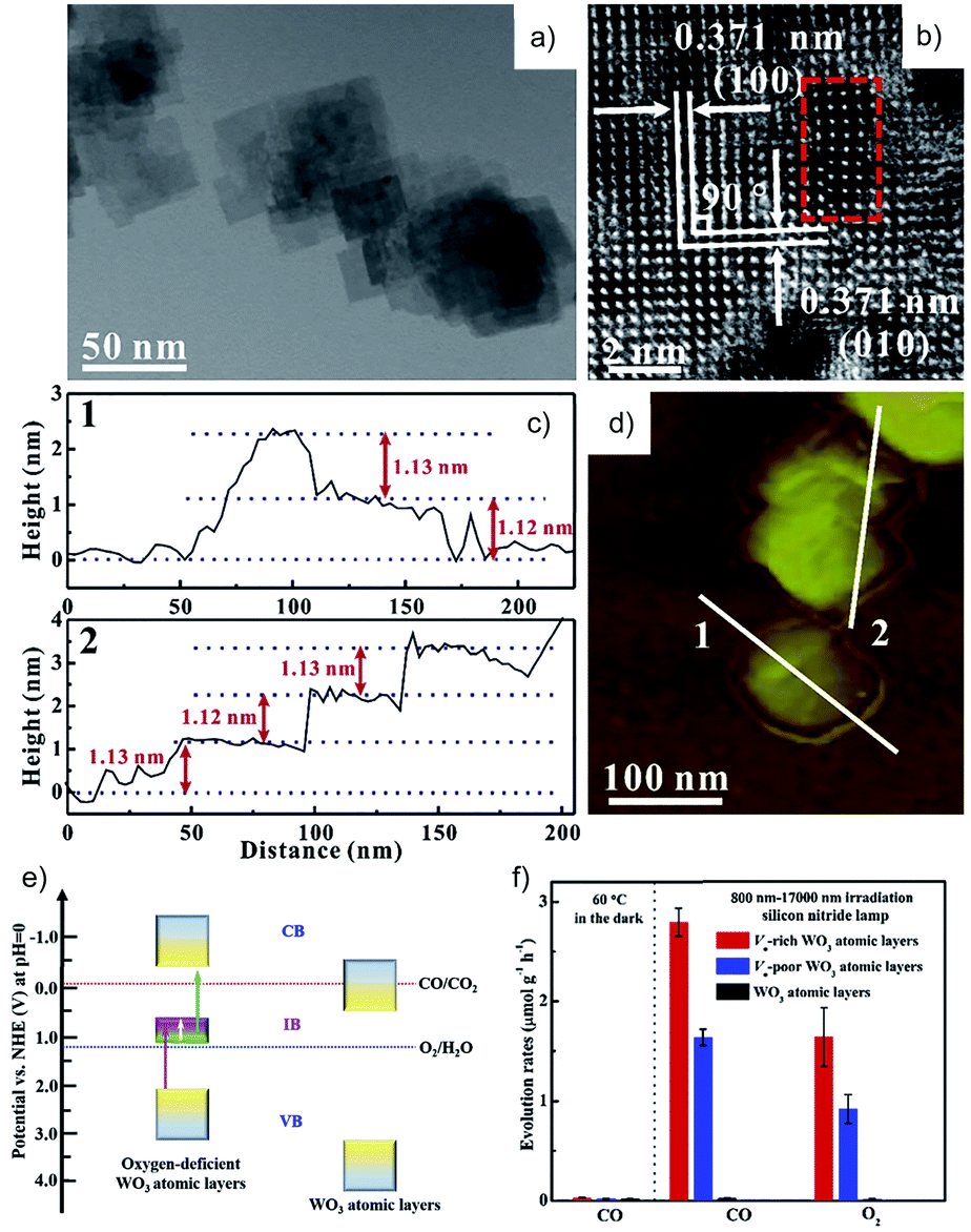 | ||
| Fig. 15 (a) TEM and (b) HRTEM images, (c) height profiles and the corresponding (d) AFM image, (e) schematic electronic band structure, and (f) photocatalytic CO2RR activity of oxygen vacancy-rich WO3 atomic layers in H2O. Reprinted with permission from ref. 86. Copyright 2018, Elsevier. | ||
Although the stoichiometric generation of reduction and oxidation products is an important indicator for authentic photocatalytic CO2RR in H2O, it is to be noted that sometimes the OER cannot be successfully observed, albeit CO2 is indeed converted to the chemicals.8 First, it is possible that back reactions occur between the CO2RR products and O2, but in this case both reduction products and O2 will be simultaneously consumed. Secondly, free O2 can be adsorbed on the photocatalyst surface in the presence of H2O, which makes it difficult to determine the actual amount of O2 produced.90–92 It is also evidenced by theoretical calculations that the adsorption affinity of O2 on C3N4 is larger than that of CO.93 Especially, oxygen vacancies on the catalyst surface can favor the adsorption of O2 and Oad species94 and formation of O2− or H2O2via reactions with electrons,95,96 and thus prevent O2 evolution from the solution. Alternatively, O2 molecules can further form a peroxide complex, except that some of them are adsorbed as physisorbed, chemisorbed and O2− species.97,98 It is worth mentioning that the surface peroxo species may also hold back the holes for H2O oxidation and increase the electron–hole recombination possibility. Moreover, the holes can be consumed by other chemical species besides H2O. Organic surfactant is frequently used during the preparation of the photocatalysts, resulting in the inevitable carbon residuals on the surface. It is possible that the organic residuals (e.g. PVP) on the photocatalysts can consume the photogenerated holes,99 resulting in no O2 generated at the early stage. Evolved O2 or photogenerated holes with lower quasi Fermi energy than the oxidation potential of the photocatalysts can also react with the photocatalysts, leading to changes in the catalysts upon the reaction.78,100 Moreover, the detection accuracy of O2 also needs to be considered since there is probable O2 leakage from the atmosphere, which can be reasonably deduced from the accompanying N2 amount also from the atmosphere.
Therefore, achieving stoichiometric CO2 reduction and H2O oxidation is still a challenge for many reasons, such as the photocatalytic activity and other chemical species that may consume the photogenerated holes, which need to be distinguished when analyzing the system activity.
3.2 Sacrificial electron donors
As mentioned above, considering all the requirements for a photocatalyst, as well as the competitive H2O reduction, it is a great challenge to close the photosynthetic cycle of CO2 reduction and H2O oxidation, especially the conversion of CO2 into four-electron (and above) reduction products. Moreover, when H2O serves as the electron donor, the resultant O2 or hydroxyl radicals (˙OH) may partially participate in oxidizing the reduction products like formic acid and/or the CO2RR intermediates. The VB position for many semiconductors with a narrow bandgap is usually unsuitable for the H2O oxidation, making it difficult to oxidize H2O, but easy to undergo self-photocorrosion.127,128 Hence, the H2O oxidation half reaction can be achieved by surrogate reactions with sacrificial electron donors that usually possess good electron donating properties, which can pick up the photogenerated holes quickly and thus improve the efficiency and photocatalyst stability, such as inorganic anions (e.g. SO32−, Cl−) and organic compounds (e.g. triethylamine (TEA), 2-propanol).129 In addition, the adoption of sacrificial electron donors also allows the utilization of semiconductors with low stability like non-oxides (i.e., CdS, CdSe, GaAs, GaP, etc.) by preventing them from being oxidized.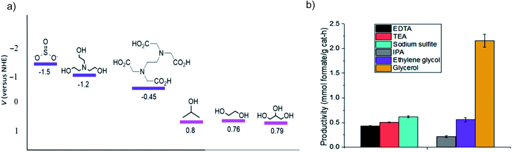 | ||
| Fig. 16 (a) Oxidation potential for SO32−, TEA, EDTA, 2-propanol, ethylene glycol and glycerol, and (b) formate production from bicarbonate photocatalytic reduction over Cu2O in the above sacrificial electron donors. Reprinted with permission from ref. 131. Copyright 2018, Cambridge University Press. | ||
Besides the thermodynamic issue of the oxidation potential, kinetic factors also play a critical role in the proton dissociation process for the electron donors, which can be determined by the number of available hydroxyl groups. For example, glycerol is considered the most efficient electron donor among several candidates with one secondary and two primary alcohol groups, which are the potential sites for oxidation. The results of ultrafast transient absorption spectroscopy indicate that the hole scavenging efficiency of glycerol (rate constant ks = 1.0 × 10¹⁰ M−1 s−1) is higher than that of methanol (ks = 1.4 × 10⁹ M−1 s−1), formaldehyde (ks = 3.1 × 10⁹ M−1 s−1) and H2O.132 A DFT study suggests that the scavenging power of five different organic compounds follows the order of glycerol > tert-butanol > 2-propanol > methanol > formic acid.133 Moreover, for the photocatalytic experiments over Cu2O, TiO2 and ZnS, glycerol is also more efficient in formate production compared to ethylene glycol and 2-propanol that possess similar oxidation potentials.131,134
However, it is not always true that the activity of electron donors follows the above rules derived from the influence of redox potential and number of oxidation sites. For instance, unlike the trend mentioned above, it is reported that methanol shows higher electron donor ability than glycerol in a TiO2/NiSx system.135 Moreover, Yanagida et al. proposed a joint influence from oxidation potential and CO2 adsorption of different aliphatic amine electron donors on CO production over CdS.136 Specifically, for TEA, Et2NMe and Et2NH with similar numbers of alkyl groups, the increased CO production yield follows the decreasing order of oxidation potential value: TEA > Et2NMe > Et2NH. For TEA (0.66 V vs. SCE), (N–Pr)3N (0.64 V vs. SCE) and (n-Bu)3N (0.62 V vs. SCE) with similar oxidation potentials, the CO yield presents a reverse trend to the ease of oxidation, with (n-Bu)3N showing the lowest performance due to the hindering effect on CO2 adsorption from the increased number of alkyl groups.
Therefore, choosing an appropriate sacrificial electron donor is complicated since its activity can be influenced by various factors. The photocatalytic CO2RR is a very complex process and the reaction conditions can be different among systems (such as photocatalyst, solvent, temperature, etc.), which can influence the charge transfer process and/or trapping ability of the electron donors. For instance, since the VB positions of distinct photocatalysts are different, the choice of electron donors is diverse considering the oxidation potential. Moreover, the solvent also has an impact on screening the electron donors as the interactions between electron donors and solvent may influence the activity. Currently, electron donors that are universally effective for all systems are still unavailable. Some common sacrificial electron donors and the corresponding applications are presented in this section.
![[double bond, length as m-dash]](https://www.rsc.org/images/entities/char_e001.gif) CHCH3/HCO2− ion pair, and then form Et2NCHCH2 and HCO2H.137 A slightly different oxidation process for TEA over CdS is presented in entry 1 of Table 2, indicating that TEA serves as an electron and proton donor, and is finally decomposed into Et2NH and CH3CHO. With a strong ability for trapping holes, tertiary amines are widely used in semiconductor systems like Pt/C–In2O3,138 CdS,136,139 metal complex/semiconductor140,141 and COF.142 Specifically, a suitable electron donor like TEOA is required for metal complex photocatalysts since they cannot directly extract electrons from H2O.140 Moreover, the electron donor can also influence the CO2RR selectivity as evidenced by the work on tertiary amines. CO2 is reduced over the CoTe photocatalyst to a small amount of CH4 in H2O, while more CO is generated when TEOA acts as the electron donor, which is probably due to the low CO adsorption on CoTe in the presence of TEOA.143 In addition, the CO2RR selectivity may also be influenced by the pH of solution caused by different electron donors.144 Maeda et al. showed that the main product over RuP/C3N4 hybrids is formic acid in a mixed DMA and TEOA basic solution,145 while it is CO in DMA and methanol acidic solution.63 Moreover, the selectivity of the CO2RR product can also be influenced by the nature of tertiary amines. Lehn et al. tested the photochemical reduction of CO2 and H2O over the Ru(2,2′-bipyridine)32+/Co2+ system using different tertiary amines as electron donors and the product ratio CO/H2 increases from 0.79 to 400, following the order of trimethylamine, TEA, tripropylamine, and TEOA.146 They suggested that these tertiary amines may influence the reaction by coordination to cobalt. Still, no detailed mechanism is available on the influence of electron donors on the photocatalytic process.
CHCH3/HCO2− ion pair, and then form Et2NCHCH2 and HCO2H.137 A slightly different oxidation process for TEA over CdS is presented in entry 1 of Table 2, indicating that TEA serves as an electron and proton donor, and is finally decomposed into Et2NH and CH3CHO. With a strong ability for trapping holes, tertiary amines are widely used in semiconductor systems like Pt/C–In2O3,138 CdS,136,139 metal complex/semiconductor140,141 and COF.142 Specifically, a suitable electron donor like TEOA is required for metal complex photocatalysts since they cannot directly extract electrons from H2O.140 Moreover, the electron donor can also influence the CO2RR selectivity as evidenced by the work on tertiary amines. CO2 is reduced over the CoTe photocatalyst to a small amount of CH4 in H2O, while more CO is generated when TEOA acts as the electron donor, which is probably due to the low CO adsorption on CoTe in the presence of TEOA.143 In addition, the CO2RR selectivity may also be influenced by the pH of solution caused by different electron donors.144 Maeda et al. showed that the main product over RuP/C3N4 hybrids is formic acid in a mixed DMA and TEOA basic solution,145 while it is CO in DMA and methanol acidic solution.63 Moreover, the selectivity of the CO2RR product can also be influenced by the nature of tertiary amines. Lehn et al. tested the photochemical reduction of CO2 and H2O over the Ru(2,2′-bipyridine)32+/Co2+ system using different tertiary amines as electron donors and the product ratio CO/H2 increases from 0.79 to 400, following the order of trimethylamine, TEA, tripropylamine, and TEOA.146 They suggested that these tertiary amines may influence the reaction by coordination to cobalt. Still, no detailed mechanism is available on the influence of electron donors on the photocatalytic process.

2-Propanol is claimed to be a better hole scavenger than methanol,147 with acetone as the photooxidation product (entry 2, Table 2). It is to be noted that the CO2 reduction product yield initially increases with increasing concentration of 2-propanol, and then decreases at higher concentration. This optimized scavenger concentration reflects the less hindered CO2 adsorption due to the large scavenger amount.148,149
Cyclohexanol can function as both solvent and electron donor, due to its better CO2 solubility and less positive oxidation potential (+0.85 V vs. NHE) than that of water oxidation.150 Song et al. studied the photocatalytic CO2RR activity in cyclohexanol over a series of materials, such as CdS/TiO2,150 ZnFe2O4/TiO2 (ref. 151) and ZnFe2O4/BiOCl.152 Formic acid is the reduction product, which further reacts with cyclohexanol to produce cyclohexyl formate, and cyclohexanol is simultaneously oxidized to cyclohexanone by the photogenerated holes (entry 3, Table 2).
The low-cost Na2SO3 is often employed in photocatalytic systems that are at the risk of photooxidation like Cu2O,36,127 CdS/Cu2S153 and ZnS,154 with Na2SO4 produced (entry 4, Table 2). An enhanced yield of the photocatalytic CO2RR product is achieved over the TiO2–CoPc system with Na2SO3 as the electron donor compared to that without Na2SO3.155 Generally, a higher concentration of Na2SO3 leads to a more effective photoreduction reaction, while a concentration plateau may exist sometimes.155 Moreover, the concentration of Na2SO3 also plays an important role in the reduction product selectivity. With P25 as the photocatalyst, gas products (H2 and CO) decrease with the increase of Na2SO3 concentration (1.66 to 6.68 g L−1), while formic acid yield follows the opposite trend with increments of up to 9 times from low to high Na2SO3 concentration.159 This may be because the Na2SO3 hole scavenger can prohibit the oxidation of the obtained organic products and thus favor the further formation of formic acid. In the case of Na2SO3 with low concentration, as soon as Na2SO3 runs out, the generated organic products will act as scavengers with gas products evolved.160,161 So the photoreduction products can be tuned by adjusting the electron donor concentration.
The S2− ion is another popular electron donor. Xie et al. analyzed the carrier dynamics with and without the S2− hole scavenger by femtosecond time-resolved transient absorption (fs-TA) spectroscopy, indicating that the charge recombination time in Na2S solution increases by 1.6-fold than that in H2O.87 Hence the lifetime of electrons is prolonged, as the photogenerated holes are consumed via the reaction with S2− ions (2S2− + 2h+ → S22−), leading to an increment of CO evolution rate by 50 times in Na2S solution compared to that in H2O.
Halide anions can also trap the photogenerated holes. For instance, Cl− has been used to improve the conversion efficiency in CO2 reduction. Tanaka et al. proved that the addition of NaCl to water can increase the selective photocatalytic conversion of CO2 to CO by two times compared to that in pure water over Ni–Al layered double hydroxides (LDHs).157 For the first time, HClO is proposed to be the oxidation product in H2O based on the experimental results (entry 5, Table 2), whose amount is in a stoichiometric ratio to CO. The photocatalytic CO2RR efficiency using NaCl as the electron donor can be further improved by controlling the morphology of the LDH-based photocatalysts at the nanoscale162 or tuning their chemical composition.163 Interestingly, Ni–V LDH shows significantly high photocatalytic CO2 reduction properties due to the use of sacrificial Cl− and the regeneration of Cl2 by V3+.163
NH3 is a typical environmental contaminant and can be removed by oxidation from water.164 The photooxidation of NH3 or NH4+ is much less demanding than H2O oxidation since ΔGθ for NH3 → N2 (18 kJ mol−1) is much less than that for H2O → O2 (237 kJ mol−1),158 which makes it more favorable as the hole scavenger for the photocatalytic CO2RR. Tanaka et al. indicated that NH3 can work as an effective electron donor for the CO2RR.165 CO and H2 are the reduction products with a rate of 0.5 mmol h−1 for CO, and stoichiometric N2 is found to be the oxidation product. They further reported enhanced CO2RR performance compared to H2O using ammonia as the reducing reagent over Ag/Ba2KTa5O15 under illumination of λ > 280 nm, with a CO production yield of 117 μmol h−1 and selectivity up to 98.6% in 0.7 mol L−1 NH3·H2O.166 Recently NH4HCO3 was also used as the electron donor, and it shows significantly higher selective CO production than other additives like NaOH, Na2CO3, KHCO3 and a Na2HPO4/NaH2PO4 mixture.167 During the photooxidation of NH3 or NH4+, it is claimed that N2H4 is the first intermediate that is more active than NH3.166,168 So N2H4·H2O can also work as an electron donor, as manifested in the Au–Cu/SrTiO3/TiO2 system.169 Besides being the electron donor, in this work N2H4·H2O also serves as the H source and reducing agent for protecting the metal from oxidation. Thus, this system shows a much higher CH4 evolution rate than that in H2O.
Besides the aforementioned organic and inorganic electron donors, other chemicals can also facilitate hole trapping and thereby enhance the photocatalytic CO2RR performance, such as ascorbic acid,170 methanol,171 EDTA172 and NaH2PO2.173 Moreover, apart from those employed in the liquid phase, H2 and CH4 are the representative gas-phase reductants.
In summary, sacrificial chemicals acting as the electron donors can consume the superfluous photogenerated holes in the semiconductors, resulting in more efficient electron utilization. However, the sacrificial electron donor is not recyclable, and needs to be supplemented during the reaction to maintain the high performance. Therefore, in most cases the product amount tends to increase nonlinearly with time, as the sacrificial electron donors are consumed during the reaction. Accordingly, designing a recyclable electron donor that can be regenerated from its oxidized state is desired. A cyclic reaction was proposed using carbon-coated In2O3 as the photocatalyst, H2O as the reductant, and TEOA as the electron donor.138 TEOA is oxidized by the photogenerated holes during the reaction and regenerated by the hydroxyl ions. However, relevant evidence is needed to support this, since water oxidation is more formidable than TEOA oxidation. Moreover, the radical cations for the tertiary amines decompose easily into a mixture, which is difficult to convert back to the initial state. Based on the computational results, Richardson et al. revealed two remote C–H activation modes for amine radical cations that might make it possible to regenerate the electron donor.174 A general strategy is thus put forward theoretically in photochemical CO2 reduction by introducing a reducing mediating reagent that can recycle amines via hydrogenation (eqn (6)–(9)).175 However, further experiments are needed to confirm this.
 | (6) |
 | (7) |
 | (8) |
Overall reaction:
| 4hν + 2CO2 + 2H2O → 2HCOOH + O2 | (9) |
4 Multifunctional CO2RR systems with effective use of the OHR
As discussed in Section 3.1, the photocatalytic CO2RR using H2O as an electron donor is an ideal choice to mimic photosynthesis. However, H2O oxidation needs a high overpotential. In addition, the evolved O2 is an undesired by-product and is difficult to separate from the CO2 reduction products. As for the sacrificial electron donors discussed in Section 3.2 (such as TEA, TEOA and 2-propanol), they are of high value, while the related oxidation products are usually useless and may cause environmental concern as well. Therefore, it is highly desirable to effectively utilize the oxidative holes to drive meaningful reactions, via integrating with the CO2RR consuming the electrons. Since waste treatment and organic transformation are common oxidation processes, efforts have been devoted to coupling the photocatalytic CO2RR with these processes.Some systems have been reported to show activity in both the photocatalytic CO2RR and useful OHR, especially the Z-scheme and cocatalyst-modified systems. For instance, Al–O-linked porous-g-C3N4/TiO2-nanotube Z-scheme composites,176 SnO2 and Ag co-modified g-C3N4,177 TiO2-coupled N-doped porous perovskite LaFeO3 nanocomposites,178 chloride and phosphate anion modified P25 TiO2 (ref. 179) and TiO2 nanotubes co-modified with MnOx and RGO180 have all shown high performance in both the photocatalytic CO2RR and degradation of 2,4-dichlorophenol. Other g-C3N4 containing heterogeneous systems181–189 or semiconductor systems like zinc silicate,190 SnO2-coupled α-Fe2O3,191 SnO2/Ag/MoS2,192 CeO2/Ti3C2-MXene,193 LaDySn2O7/SnSe,194 N-doped graphene/Zn1.231Ge0.689N1.218O0.782,195 and Pt,N co-doped BiOCl196 have also exhibited activity for both the CO2RR and degradation of various organic pollutants (such as rhodamine B, methyl orange, methylene blue (MB), phenol, tetracycline, acetaldehyde, 4-chlorophenol, and benzyl alcohol). However, it should be pointed out that in the aforementioned work the CO2RR and OHR are tested in separate experiments. For real applications, it is highly desirable to carry out the two half reactions simultaneously in a single multifunctional system, which is helpful for decreasing energy demand and promoting the overall reaction for a sustainable chemistry. In this regard, since the concept of (photo)electrochemical setup is useful for the photocatalytic system design, the related advances will be presented in this section for a deep and broad reference.
4.1 CO2 reduction combined with waste treatment
For CO2 reduction in tandem with waste treatment by the (photo)electrochemical method, the waste oxidation can accelerate the overall conversion efficiency via lowering the required input energy as compared to the OER. A recent analysis of Gibbs free energy indicates that for the electrocatalytic CO2RR in H2O, ∼90% of the overall energy is used to drive the H2O oxidation.197 Using an alternative OHR with superior thermodynamics can lower the energy requirement for a specific system. For instance, the replacement of H2O oxidation by glycerol oxidation can reduce the electricity input by 53% during the CO2 electroreduction.197 Another study by Guo et al. employed an integrated cell with Cu nanowires as the cathode for CO2 reduction and Sb/SnO2–TiO2 nanotubes as the anode for photoelectrocatalytic phenol oxidation (Fig. 17a).198 Coupling these two reactions leads to a decreased energy consumption by 51.33% compared to the sum of the two half reduction and oxidation reactions (Fig. 17b). Moreover, Bevilacqua et al. developed an electrocatalytic device for the CO2RR to yield useful chemicals (CH4, C2H4, and HCOO−) at the cathode and ethanol oxidation to acetate at the anode, for which the operation potential decreases as compared to the OER at the anode.199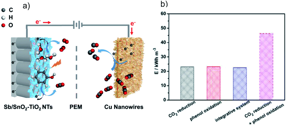 | ||
| Fig. 17 (a) Schematic diagram of the integrated cell with Cu nanowires as the cathode for CO2 reduction and Sb/SnO2–TiO2 nanotubes as the anode for photoelectrocatalytic phenol oxidation, and (b) energy consumption for different reaction systems. Reprinted with permission from ref. 198. Copyright 2019, Wiley-VCH. | ||
Apart from the organic degradation, other waste removal reactions can also be used as the OHR. Poisonous SO2 removal and CO2 reduction are integrated in a photoelectrochemical cell, with improved CO2RR efficiency and faradaic efficiency of the corresponding products. The high performance benefits from the introduction of SO2 because of its lower activation energy and faster kinetics than those of H2O oxidation.200 Moreover, simultaneous efficient As(III) oxidation to As(V) over Ti/Ir1−xTaxOy/TiO2 and CO2 reduction to formate on a Bi electrode has been realized, driven by a photovoltaic device.201 In addition, Li et al. proposed a solar-driven electrochemical system to simultaneously convert CO2 and H2S, the usual contaminants in natural gas, respectively, to CO and S, with the configuration shown in Fig. 18.202 The oxidation of H2S is achieved with the aid of EDTA–Fe2+ on graphene, and the CO2RR occurs over the graphene-encapsulated ZnO catalyst.
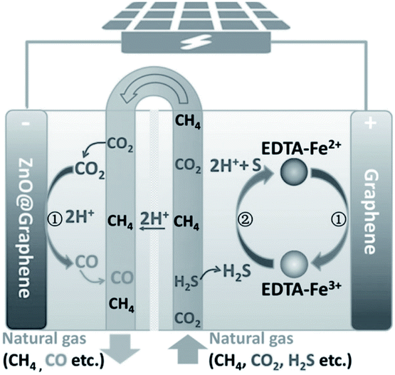 | ||
| Fig. 18 Configuration used for simultaneous conversion of CO2 and H2S. Reprinted with permission from ref. 202. Copyright 2018, Wiley-VCH. | ||
4.2 One-pot conversion of pollutants to value-added chemicals
Considering that the oxidation of organic pollutants usually generates CO2 as the final product, utilization of the obtained CO2 can make it possible to convert organic pollutants to useful chemicals. Such a carbon cycle is an important resource utilization method, and may realize the real applications of reduction and oxidation reactions in a synergistic way.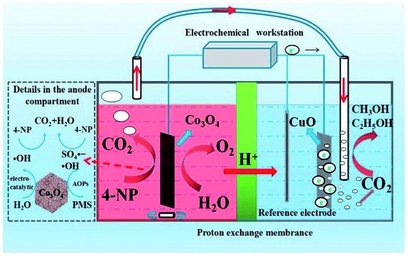 | ||
| Fig. 19 Setup used for one-pot conversion of 4-nitrophenol to methanol and ethanol and the possible reaction processes. Reprinted with permission from ref. 204. Copyright 2019, Elsevier. | ||
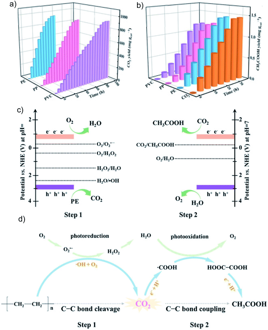 | ||
| Fig. 20 The yield of (a) CO2 and (b) acetic acid during photoconversion of PE, PP and PVC over Nb2O5, (c) band edge positions for Nb2O5 and related redox potentials, and (d) mechanism for C–C cleavage and coupling during PE photoconversion to acetic acid. Reprinted with permission from ref. 208. Copyright 2020, Wiley-VCH. | ||
4.3 CO2RR integrated with chemical oxidative synthesis
Forming value-added products from both the reduction and oxidation half reactions is an appealing concept, which makes full utilization of the electrons and holes. There are some reports on tandem CO2 reduction and selective organic oxidation to produce value-added chemicals. For example, the photocatalytic CO2RR coupled with selective oxidation of alcohols is realized over a Ag/TiO2 composite, with a maximum methanol yield of 358.7 μmol g−1 for the CO2RR and 91.7% aromatic alcohol oxidation to aldehyde.209 Moreover, simultaneous photocatalytic CO2 reduction and benzyl alcohol oxidation to benzyl acetate (or benzaldehyde) is achieved over a Cu2O/Cu (or Cu2O-RGO/BiVO4) composite.210,211 Li et al. reported an OHR involving conversion of four alcohols to high value-added hydrocarbon products with >78% yield and CO2 reduction to CO with a high faradaic efficiency.212 However, some alcohols may not be the ideal resource for the oxidation synthesis considering their value. Alternatively, using a waste product or common synthetic material for valuable chemical oxidative synthesis is usually preferred.Llorente et al. designed a system consisting of CO2 reduction to CO at the cathode coupled with syringaldehyde and o-phenylenediamine oxidative condensation to 2-(3,5-dimethoxy-4-hydroxyphenyl) benzimidazole at the anode.213 Furthermore, the direct oxidation of organic materials to useful chemicals is more frequently used. A BiOBr photoanode coupled with a CuO photocathode can yield useful chemicals by merging the oxidation of the tetracycline pollutant with photoelectrocatalytic reduction of CO2.214 Wu et al. combined the photocatalytic CO2RR with oxidative synthesis of pinacol, an important pharmaceutical intermediate, from 1-phenylethanol over CdSe/CdS quantum dots, with the utilization ratio of photogenerated electrons and holes close to 1.215 The oxidative conversion of pinacol from 1-phenylethanol can reach 98% yield, which also provides electrons and protons for highly selective conversion of CO2 to CO. Moreover, the reduction product CO and oxidation product pinacol can spontaneously separate in different phases. Another pharmaceutical intermediate, dihydroisoquinoline (DHIQ) can be obtained by dehydrogenation of the corresponding tetrahydroisoquinoline (THIQ) precursors. The lower oxidation potential of THIQ than water makes it a possible candidate to boost the OHR. Zhao et al. integrated the photocatalytic CO2RR with selective THIQ oxidation to DHIQ over an InP–In2O3 junction with a CO yield of 170 μmol g−1 h−1.216
5 Conclusion & perspectives
In summary, this review highlights the progress on managing the OHR in photocatalytic CO2 conversion. The related studies cover materials design, electron donors and valuable oxidation integrated with CO2 reduction.Investigations on materials design mainly aim at regulating the hole behavior, such as accelerating the transfer process and/or preserving the high driving force. Element modification like with Cl− can help trap photogenerated holes, facilitate the charge separation, and thereby improve the photocatalytic CO2RR. Similarly, loading oxidation cocatalysts can promote extraction and trapping of the photogenerated holes, and serve as active sites for the OHR. Furthermore, dual cocatalysts stand out as a better choice due to parallel extraction of the electrons and holes to the respective reaction sites. Different from dual cocatalysts, Z-scheme systems simultaneously modulate the behavior of electrons and holes by retaining their high driving force and enhancing the carrier lifetime.
Electron donors play an important role in accelerating the reaction process. The photocatalytic CO2RR in H2O is an ideal case but is very challenging for the time being. So far, only a few studies clearly reported the overall CO2 reduction with O2 as the oxidation product, but with unsatisfactory efficiency. Higher performance can be achieved by replacing H2O with sacrificial electron donors, which can react with the photogenerated holes very quickly. However, there is still a lack of detailed and systematic study on the oxidation mechanism of the electron donor and its impact on the CO2RR, which makes it difficult to rationally design highly efficient systems by matching the appropriate electron donor. Moreover, sacrificial electron donors are not the ultimate solution, as the experiments will slow down as soon as they run out and many sacrificial electron donors are more valuable compared with the useless oxidation products. Accordingly, it is hard to say whether the benefit from the CO2RR can make up for the cost of the sacrificial chemicals, but one major strength of sacrificial agents is their contribution to the studies that only focus on the reduction half reactions.
Integrating the CO2RR with a meaningful OHR offers a possible approach to address the above concern. Deliberate integration of the two half reactions can result in the maximum use of the electrons and holes, and thus high efficiency of the full reaction. This has been demonstrated by combining the CO2RR with waste treatment or oxidative organic transformation. However, so far only a few studies have been devoted to this. More efforts are needed to construct effective systems to further increase the activity and product selectivity for both half reactions. Specifically, a better understanding of both half reactions is highly desired so that a perfect match between the reduction and oxidation reactions can be established and, accordingly, a high overall efficiency can be achieved.
To conclude, study of the OHR that accompanies the CO2RR is quite necessary for long-term research. Although significant achievements have been made hitherto, there is still a long way to go to realize the expected practical applications. Advances in the photocatalytic CO2RR are often hindered by the sophisticated multi-electron–hole involving reaction processes, low quantum efficiency, and poor photocatalyst stability. In future studies, a more rational design of the photocatalyst and better understanding of the mechanism are needed. It is highly desirable to explore new photocatalysts for the overall photocatalytic CO2 reduction, especially for synchronously managing the behavior of electrons and holes. Systematic investigations should be focused on the mechanism of CO2 reduction, especially that coupled with a sacrificial electron donor or meaningful oxidation.
Conflicts of interest
There are no conflicts to declare.Acknowledgements
This work was supported by the Belt and Road Initiative by the Chinese Academy of Sciences (121D11KYSB20170050), National Natural Science Foundation of China (21972029), and Strategic Priority Research Program of the Chinese Academy of Sciences (XDB36000000).References
- T. Sakakura, J. C. Choi and H. Yasuda, Chem. Rev., 2007, 107, 2365–2387 CrossRef CAS
.
- N. N. Vu, S. Kaliaguine and T. O. Do, Adv. Funct. Mater., 2019, 29, 1901825 CrossRef
- J. L. White, M. F. Baruch, J. E. Pander III, Y. Hu, I. C. Fortmeyer, J. E. Park, T. Zhang, K. Liao, J. Gu, Y. Yan, T. W. Shaw, E. Abelev and A. B. Bocarsly, Chem. Rev., 2015, 115, 12888–12935 CrossRef CAS
- X. Li, J. Yu, M. Jaroniec and X. Chen, Chem. Rev., 2019, 119, 3962–4179 CrossRef CAS
- S. N. Habisreutinger, L. Schmidt-Mende and J. K. Stolarczyk, Angew. Chem., Int. Ed., 2013, 52, 7372–7408 CrossRef CAS
- J. Fu, K. Jiang, X. Qiu, J. Yu and M. Liu, Mater. Today, 2020, 32, 222–243 CrossRef CAS
- S. Yan, J. Wang, H. Gao, N. Wang, H. Yu, Z. Li, Y. Zhou and Z. Zou, Adv. Funct. Mater., 2013, 23, 758–763 CrossRef CAS
- J. Tang, J. R. Durrant and D. R. Klug, J. Am. Chem. Soc., 2008, 130, 13885–13891 CrossRef CAS
- P. V. Kamat, Chem. Rev., 1993, 93, 267–300 CrossRef CAS
- J. Z. Y. Tan and M. M. Maroto-Valer, J. Mater. Chem. A, 2019, 7, 9368–9385 RSC
- A. Meng, L. Zhang, B. Cheng and J. Yu, Adv. Mater., 2019, 31, e1807660 CrossRef
- W. Zhang, A. R. Mohamed and W. J. Ong, Angew. Chem., Int. Ed., 2020 DOI:10.1002/anie.201914925
- L. J. Guo, Y. J. Wang and T. He, Chem. Rec., 2016, 16, 1918–1933 CrossRef CAS
- K. Li, X. An, K. H. Park, M. Khraisheh and J. Tang, Catal. Today, 2014, 224, 3–12 CrossRef CAS
- E. Karamian and S. Sharifnia, J. CO2 Util., 2016, 16, 194–203 CrossRef CAS
- W. Tu, Y. Zhou and Z. Zou, Adv. Mater., 2014, 26, 4607–4626 CrossRef CAS
- A. D. Handoko, K. Li and J. Tang, Curr. Opin. Chem. Eng., 2013, 2, 200–206 CrossRef
- J. Tang, A. J. Cowan, J. R. Durrant and D. R. Klug, J. Phys. Chem. C, 2011, 115, 3143–3150 CrossRef CAS
- S. Wang, K. Teramura, T. Hisatomi, K. Domen, H. Asakura, S. Hosokawa and T. Tanaka, ACS Appl. Energy Mater., 2020, 3, 1468–1475 CrossRef CAS
- S. L. Liew, Z. Zhang, T. W. G. Goh, G. S. Subramanian, H. L. D. Seng, T. S. A. Hor, H. K. Luo and D. Z. Chi, Int. J. Hydrogen Energy, 2014, 39, 4291–4298 CrossRef CAS
- K. Wang, J. Fu and Y. Zheng, Appl. Catal., B, 2019, 254, 270–282 CrossRef CAS
- R. Zhang, Y. Y. Fang, T. Chen, F. L. Qu, Z. Liu, G. Du, A. M. Asiri, T. Gao and X. P. Sun, ACS Sustainable Chem. Eng., 2017, 5, 7502–7506 CrossRef CAS
- R. Nakamura, T. Tanaka and Y. Nakato, J. Phys. Chem. B, 2004, 108, 10617–10620 CrossRef CAS
- L. Huang, R. Li, R. Chong, G. Liu, J. Han and C. Li, Catal. Sci. Technol., 2014, 4, 2913–2918 RSC
- X. Zhang, H. Cui, M. Humayun, Y. Qu, N. Fan, X. Sun and L. Jing, Sci. Rep., 2016, 6, 21430 CrossRef CAS
- J. Wu, H. Lu, X. Zhang, F. Raziq, Y. Qu and L. Jing, Chem. Commun., 2016, 52, 5027–5029 RSC
- J. Li, X. Zhang, F. Raziq, J. Wang, C. Liu, Y. Liu, J. Sun, R. Yan, B. Qu, C. Qin and L. Jing, Appl. Catal., B, 2017, 218, 60–67 CrossRef CAS
- L. Yu, X. Ba, M. Qiu, Y. Li, L. Shuai, W. Zhang, Z. Ren and Y. Yu, Nano Energy, 2019, 60, 576–582 CrossRef CAS
- X. Zhang, X. Zhang, W. Ali, X. Chen, K. Hu, Z. Li, Y. Qu, L. Bai, Y. Gao and L. Jing, ChemCatChem, 2019, 11, 6282–6287 CrossRef CAS
- T. Yoshinaga, M. Saruyama, A. Xiong, Y. Ham, Y. Kuang, R. Niishiro, S. Akiyama, M. Sakamoto, T. Hisatomi, K. Domen and T. Teranishi, Nanoscale, 2018, 10, 10420–10427 RSC
- D. Liu, L. Jing, P. Luan, J. Tang and H. Fu, ACS Appl. Mater. Interfaces, 2013, 5, 4046–4052 CrossRef CAS
- Y. Zheng, Y. Jiao, Y. Zhu, Q. Cai, A. Vasileff, L. H. Li, Y. Han, Y. Chen and S. Z. Qiao, J. Am. Chem. Soc., 2017, 139, 3336–3339 CrossRef CAS
- B. H. Meekins and P. V. Kamat, J. Phys. Chem. Lett., 2011, 2, 2304–2310 CrossRef CAS
- M. W. Kanan and D. G. Nocera, Science, 2008, 321, 1072–1075 CrossRef CAS
- M. Barroso, A. J. Cowan, S. R. Pendlebury, M. Gratzel, D. R. Klug and J. R. Durrant, J. Am. Chem. Soc., 2011, 133, 14868–14871 CrossRef CAS
- A. D. Handoko and J. Tang, Int. J. Hydrogen Energy, 2013, 38, 13017–13022 CrossRef CAS
- J. Lin, Z. Pan and X. Wang, ACS Sustainable Chem. Eng., 2013, 2, 353–358 CrossRef
- J. Zhou, W. Chen, C. Sun, L. Han, C. Qin, M. Chen, X. Wang, E. Wang and Z. Su, ACS Appl. Mater. Interfaces, 2017, 9, 11689–11695 CrossRef CAS
- S. Shoji, A. Yamaguchi, E. Sakai and M. Miyauchi, ACS Appl. Mater. Interfaces, 2017, 9, 20613–20619 CrossRef CAS
- Y. Bai, L. Ye, L. Wang, X. Shi, P. Wang and W. Bai, Environ. Sci.: Nano, 2016, 3, 902–909 RSC
- Q. Liu, Y. Zhou, J. Kou, X. Chen, Z. Tian, J. Gao, S. Yan and Z. Zou, J. Am. Chem. Soc., 2010, 132, 14385–14387 CrossRef CAS
- Q. Liu, Y. Zhou, Z. Tian, X. Chen, J. Gao and Z. Zou, J. Mater. Chem., 2012, 22, 2033–2038 RSC
- C. Dong, S. Hu, M. Xing and J. Zhang, Nanotechnology, 2018, 29, 154005 CrossRef
- A. Li, X. Chang, Z. Huang, C. Li, Y. Wei, L. Zhang, T. Wang and J. Gong, Angew. Chem., Int. Ed., 2016, 55, 13734–13738 CrossRef CAS
- A. Li, T. Wang, X. Chang, Z. J. Zhao, C. Li, Z. Huang, P. Yang, G. Zhou and J. Gong, Chem. Sci., 2018, 9, 5334–5340 RSC
- C. Dong, M. Xing and J. Zhang, Mater. Horiz., 2016, 3, 608–612 RSC
- Z. Jiang, D. Ding, L. Wang, Y. Zhang and L. Zan, Catal. Sci. Technol., 2017, 7, 3065–3072 RSC
- M. S. Akple, J. Low, S. Liu, B. Cheng, J. Yu and W. Ho, J. CO2 Util., 2016, 16, 442–449 CrossRef CAS
- A. Meng, L. Zhang, B. Cheng and J. Yu, ACS Appl. Mater. Interfaces, 2019, 11, 5581–5589 CrossRef CAS
- Y. Bai, L. Ye, L. Wang, X. Shi, P. Wang, W. Bai and P. K. Wong, Appl. Catal., B, 2016, 194, 98–104 CrossRef CAS
- J. Jin, J. Yu, D. Guo, C. Cui and W. Ho, Small, 2015, 11, 5262–5271 CrossRef CAS
- W. Shi, X. Guo, C. Cui, K. Jiang, Z. Li, L. Qu and J.-C. Wang, Appl. Catal., B, 2019, 243, 236–242 CrossRef CAS
- H. Li, Y. Gao, Y. Zhou, F. Fan, Q. Han, Q. Xu, X. Wang, M. Xiao, C. Li and Z. Zou, Nano Lett., 2016, 16, 5547–5552 CrossRef CAS
- Y. Yang, J. Wu, T. Xiao, Z. Tang, J. Shen, H. Li, Y. Zhou and Z. Zou, Appl. Catal., B, 2019, 255, 117771 CrossRef CAS
- Y. Jiang, J. Liao, H. Chen, H. Zhang, J. Li, X. Wang and D. Kuang, Chem, 2020, 6, 766–780 CAS
- H. Tada, T. Mitsui, T. Kiyonaga, T. Akita and K. Tanaka, Nat. Mater., 2006, 5, 782–786 CrossRef CAS
- J. Low, B. Dai, T. Tong, C. Jiang and J. Yu, Adv. Mater., 2019, 31, e1802981 CrossRef
- J. Yang, J. Hao, S. Xu, Q. Wang, J. Dai, A. Zhang and X. Pang, ACS Appl. Mater. Interfaces, 2019, 11, 32025–32037 CrossRef CAS
- Y. Wang, Z. Zhang, L. Zhang, Z. Luo, J. Shen, H. Lin, J. Long, J. C. S. Wu, X. Fu, X. Wang and C. Li, J. Am. Chem. Soc., 2018, 140, 14595–14598 CrossRef CAS
- M. E. Aguirre, R. Zhou, A. J. Eugene, M. I. Guzman and M. A. Grela, Appl. Catal., B, 2017, 217, 485–493 CrossRef CAS
- T. Takayama, K. Sato, T. Fujimura, Y. Kojima, A. Iwase and A. Kudo, Faraday Discuss., 2017, 198, 397–407 RSC
- J. S. DuChene, G. Tagliabue, A. J. Welch, W. H. Cheng and H. A. Atwater, Nano Lett., 2018, 18, 2545–2550 CrossRef CAS
- R. Kuriki, O. Ishitani and K. Maeda, ACS Appl. Mater. Interfaces, 2016, 8, 6011–6018 CrossRef CAS
- N. M. Dimitrijevic, B. K. Vijayan, O. G. Poluektov, T. Rajh, K. A. Gray, H. He and P. Zapol, J. Am. Chem. Soc., 2011, 133, 3964–3971 CrossRef CAS
- J. C. Wang, H. C. Yao, Z. Y. Fan, L. Zhang, J. S. Wang, S. Q. Zang and Z. J. Li, ACS Appl. Mater. Interfaces, 2016, 8, 3765–3775 CrossRef CAS
- X. Li, J. Wen, J. Low, Y. Fang and J. Yu, Sci. China: Chem., 2014, 57, 70–100 Search PubMed
- Z. Chen, J. J. Concepcion, M. K. Brennaman, P. Kang, M. R. Norris, P. G. Hoertz and T. J. Meyer, Proc. Natl. Acad. Sci. U. S. A., 2012, 109, 15606–15611 CrossRef CAS
- T. Inoue, A. Fujishima, S. Konishi and K. Honda, Nature, 1979, 277, 637–638 CrossRef CAS
- H. Wang, Y. Wang, L. Guo, X. Zhang, C. Ribeiro and T. He, Chin. J. Catal., 2020, 41, 131–139 CrossRef CAS
- T. Di, J. Zhang, B. Cheng, J. Yu and J. Xu, Sci. China: Chem., 2018, 61, 344–350 CrossRef CAS
- L. F. Garay-Rodríguez, L. M. Torres-Martínez and E. Moctezuma, J. Energy Chem., 2019, 37, 18–28 CrossRef
- J. Jin, Y. Wang and T. He, RSC Adv., 2015, 5, 100244–100250 RSC
- K. Teramura, S. Iguchi, Y. Mizuno, T. Shishido and T. Tanaka, Angew. Chem., Int. Ed., 2012, 51, 8008–8011 CrossRef CAS
- Y. Huang, Y. Wang, Y. Bi, J. Jin, M. F. Ehsan, M. Fu and T. He, RSC Adv., 2015, 5, 33254–33261 RSC
- Y. F. Mu, W. Zhang, X. X. Guo, G. X. Dong, M. Zhang and T. B. Lu, ChemSusChem, 2019, 12, 4769–4774 CrossRef CAS
- Y. A. Wu, I. McNulty, C. Liu, K. C. Lau, Q. Liu, A. P. Paulikas, C.-J. Sun, Z. Cai, J. R. Guest, Y. Ren, V. Stamenkovic, L. A. Curtiss, Y. Liu and T. Rajh, Nat. Energy, 2019, 4, 957–968 CrossRef CAS
- K. Teramura and T. Tanaka, Phys. Chem. Chem. Phys., 2018, 20, 8423–8431 RSC
- K. Ogura, M. Kawano, J. Yano and Y. Sakata, J. Photochem. Photobiol., A, 1992, 66, 91–97 CrossRef CAS
- K. Iizuka, T. Wato, Y. Miseki, K. Saito and A. Kudo, J. Am. Chem. Soc., 2011, 133, 20863–20868 CrossRef CAS
- T. Takayama, K. Tanabe, K. Saito, A. Iwase and A. Kudo, Phys. Chem. Chem. Phys., 2014, 16, 24417–24422 RSC
- T. Takayama, A. Iwase and A. Kudo, Bull. Chem. Soc. Jpn., 2015, 88, 538–543 CrossRef CAS
- H. Nakanishi, K. Iizuka, T. Takayama, A. Iwase and A. Kudo, ChemSusChem, 2017, 10, 112–118 CrossRef CAS
- X. Chen, Y. Zhou, Q. Liu, Z. Li, J. Liu and Z. Zou, ACS Appl. Mater. Interfaces, 2012, 4, 3372–3377 CrossRef CAS
- Y. Zhou, Z. Tian, Z. Zhao, Q. Liu, J. Kou, X. Chen, J. Gao, S. Yan and Z. Zou, ACS Appl. Mater. Interfaces, 2011, 3, 3594–3601 CrossRef CAS
- Q. Han, X. Bai, Z. Man, H. He, L. Li, J. Hu, A. Alsaedi, T. Hayat, Z. Yu, W. Zhang, J. Wang, Y. Zhou and Z. Zou, J. Am. Chem. Soc., 2019, 141, 4209–4213 CrossRef CAS
- L. Liang, X. Li, Y. Sun, Y. Tan, X. Jiao, H. Ju, Z. Qi, J. Zhu and Y. Xie, Joule, 2018, 2, 1004–1016 CrossRef CAS
- L. Liang, X. Li, J. Zhang, P. Ling, Y. Sun, C. Wang, Q. Zhang, Y. Pan, Q. Xu, J. Zhu, Y. Luo and Y. Xie, Nano Energy, 2020, 69, 104421 CrossRef CAS
- M. Wang, D. Wang and Z. Li, Appl. Catal., B, 2016, 183, 47–52 CrossRef CAS
- M. Lu, J. Liu, Q. Li, M. Zhang, M. Liu, J. L. Wang, D. Q. Yuan and Y. Q. Lan, Angew. Chem., Int. Ed., 2019, 58, 12392–12397 CrossRef CAS
- I. H. Tseng, W.-C. Chang and J. C. S. Wu, Appl. Catal., B, 2002, 37, 37–48 CrossRef CAS
- H. Yamashita, H. Nishiguchi, N. Kamada, M. Anpo, Y. Teraoka, H. Hatano, S. Ehara, K. Kikui, L. Palmisano, A. Sclafani, M. Schiavello and M. A. Fox, Res. Chem. Intermed., 1994, 20, 815–823 CrossRef CAS
- G. Munuera, V. Rives-Arnau and A. Saucedo, J. Chem. Soc., Faraday Trans. 1, 1979, 75, 736–747 RSC
- B. Zhu, S. Wageh, A. A. Al-Ghamdi, S. Yang, Z. Tian and J. Yu, Catal. Today, 2019, 335, 117–127 CrossRef CAS
- E. Lira, S. Wendt, P. Huo, J. O. Hansen, R. Streber, S. Porsgaard, Y. Wei, R. Bechstein, E. Laegsgaard and F. Besenbacher, J. Am. Chem. Soc., 2011, 133, 6529–6532 CrossRef CAS
- P. Salvador and C. Gutiérrez, Surf. Sci., 1983, 124, 398–406 CrossRef CAS
- M. V. Rao, K. Rajeshwar, V. R. P. Verneker and J. DuBow, J. Phys. Chem., 1980, 84, 1987–1991 CrossRef CAS
- J. Kiwi and M. Graetzel, J. Phys. Chem., 1984, 88, 1302–1307 CrossRef CAS
- R. Nakamura and Y. Nakato, J. Am. Chem. Soc., 2004, 126, 1290–1298 CrossRef CAS
- K. L. Bae, J. Kim, C. K. Lim, K. M. Nam and H. Song, Nat. Commun., 2017, 8, 1156 CrossRef
- T. Abe, E. Suzuki, K. Nagoshi, K. Miyashita and M. Kaneko, J. Phys. Chem. B, 1999, 103, 1119–1123 CrossRef CAS
- K. Sayama and H. Arakawa, J. Phys. Chem., 1993, 97, 531–533 CrossRef CAS
- Z. Wang, K. Teramura, S. Hosokawa and T. Tanaka, Appl. Catal., B, 2015, 163, 241–247 CrossRef CAS
- H. Yoshida, L. Zhang, M. Sato, T. Morikawa, T. Kajino, T. Sekito, S. Matsumoto and H. Hirata, Catal. Today, 2015, 251, 132–139 CrossRef CAS
- A. Anzai, N. Fukuo, A. Yamamoto and H. Yoshida, Catal. Commun., 2017, 100, 134–138 CrossRef CAS
- R. Pang, K. Teramura, H. Asakura, S. Hosokawa and T. Tanaka, Appl. Catal., B, 2017, 218, 770–778 CrossRef CAS
- K. Li, A. D. Handoko, M. Khraisheh and J. Tang, Nanoscale, 2014, 6, 9767–9773 RSC
- S. Iguchi, K. Teramura, S. Hosokawa and T. Tanaka, Catal. Sci. Technol., 2016, 6, 4978–4985 RSC
- K. Teramura, H. Tatsumi, Z. Wang, S. Hosokawa and T. Tanaka, Bull. Chem. Soc. Jpn., 2015, 88, 431–437 CrossRef CAS
- Z. Huang, K. Teramura, S. Hosokawa and T. Tanaka, Appl. Catal., B, 2016, 199, 272–281 CrossRef CAS
- Z. Huang, S. Yoshizawa, K. Teramura, H. Asakura, S. Hosokawa and T. Tanaka, ACS Omega, 2017, 2, 8187–8197 CrossRef CAS
- Z. Huang, K. Teramura, H. Asakura, S. Hosokawa and T. Tanaka, Catal. Today, 2018, 300, 173–182 CrossRef CAS
- M. Yamamoto, T. Yoshida, N. Yamamoto, T. Nomoto, Y. Yamamoto, S. Yagi and H. Yoshida, J. Mater. Chem. A, 2015, 3, 16810–16816 RSC
- K. Teramura, Z. Wang, S. Hosokawa, Y. Sakata and T. Tanaka, Chemistry, 2014, 20, 9906–9909 CrossRef CAS
- Z. Wang, K. Teramura, Z. Huang, S. Hosokawa, Y. Sakata and T. Tanaka, Catal. Sci. Technol., 2016, 6, 1025–1032 RSC
- H. Tatsumi, K. Teramura, Z. Huang, Z. Wang, H. Asakura, S. Hosokawa and T. Tanaka, Langmuir, 2017, 33, 13929–13935 CrossRef CAS
- Z. Huang, K. Teramura, H. Asakura, S. Hosokawa and T. Tanaka, J. Mater. Chem. A, 2017, 5, 19351–19357 RSC
- S. Iguchi, Y. Hasegawa, K. Teramura, S. Kidera, S. Kikkawa, S. Hosokawa, H. Asakura and T. Tanaka, Sustainable Energy Fuels, 2017, 1, 1740–1747 RSC
- R. Pang, K. Teramura, H. Tatsumi, H. Asakura, S. Hosokawa and T. Tanaka, Chem. Commun., 2018, 54, 1053–1056 RSC
- R. Pang, K. Teramura, H. Asakura, S. Hosokawa and T. Tanaka, ACS Sustainable Chem. Eng., 2018, 7, 2083–2090 CrossRef
- S. Kikkawa, K. Teramura, H. Asakura, S. Hosokawa and T. Tanaka, J. Phys. Chem. C, 2018, 122, 21132–21139 CrossRef CAS
- Z. Wang, K. Teramura, S. Hosokawa and T. Tanaka, J. Mater. Chem. A, 2015, 3, 11313–11319 RSC
- L. Hao, L. Kang, H. Huang, L. Ye, K. Han, S. Yang, H. Yu, M. Batmunkh, Y. Zhang and T. Ma, Adv. Mater., 2019, 31, e1900546 CrossRef
- L. Wang, J. Wan, Y. Zhao, N. Yang and D. Wang, J. Am. Chem. Soc., 2019, 141, 2238–2241 CrossRef CAS
- W.-K. Jo, S. Kumar, S. Eslava and S. Tonda, Appl. Catal., B, 2018, 239, 586–598 CrossRef CAS
- N. T. Thanh Truc, L. Giang Bach, N. Thi Hanh, T. D. Pham, N. Thi Phuong Le Chi, D. T. Tran, M. V. Nguyen and V. N. Nguyen, J. Colloid Interface Sci., 2019, 540, 1–8 CrossRef
- P. Li, Y. Zhou, H. Li, Q. Xu, X. Meng, X. Wang, M. Xiao and Z. Zou, Chem. Commun., 2015, 51, 800–803 RSC
- X. An, K. Li and J. Tang, ChemSusChem, 2014, 7, 1086–1093 CrossRef CAS
- J. A. Mendoza, H. K. Kim, H. K. Park and K. Y. Park, Korean J. Chem. Eng., 2012, 29, 1483–1486 CrossRef CAS
- H. Yoneyama, Catal. Today, 1997, 39, 169–175 CrossRef CAS
- M. J. Berr, P. Wagner, S. Fischbach, A. Vaneski, J. Schneider, A. S. Susha, A. L. Rogach, F. Jäckel and J. Feldmann, Appl. Phys. Lett., 2012, 100, 223903 CrossRef
- H. Pan and M. D. Heagy, MRS Commun., 2018, 8, 1173–1177 CrossRef CAS
- N. M. Dimitrijevic, I. A. Shkrob, D. J. Gosztola and T. Rajh, J. Phys. Chem. C, 2011, 116, 878–885 CrossRef
- C. Di Valentin and D. Fittipaldi, J. Phys. Chem. Lett., 2013, 4, 1901–1906 CrossRef CAS
- D. P. Leonard, H. Pan and M. D. Heagy, ACS Appl. Mater. Interfaces, 2015, 7, 24543–24549 CrossRef CAS
- Y. Wei, G. Cheng, J. Xiong, J. Zhu, Y. Gan, M. Zhang, Z. Li and S. Dou, J. Energy Chem., 2019, 32, 45–56 CrossRef
- S. Yanagida, M. Kanemoto, K.-i. Ishihara, Y. Wada, T. Sakata and H. Mori, Bull. Chem. Soc. Jpn., 1997, 70, 2063–2070 CrossRef CAS
- B. K. Carpenter, J. Phys. Chem. A, 2007, 111, 3719–3726 CrossRef CAS
- Y. X. Pan, Y. You, S. Xin, Y. Li, G. Fu, Z. Cui, Y. L. Men, F. F. Cao, S. H. Yu and J. B. Goodenough, J. Am. Chem. Soc., 2017, 139, 4123–4129 CrossRef CAS
- H. Fujiwara, H. Hosokawa, K. Murakoshi, Y. Wada, S. Yanagida, T. Okada and H. Kobayashi, J. Phys. Chem. B, 1997, 101, 8270–8278 CrossRef CAS
- S. Sato, T. Morikawa, S. Saeki, T. Kajino and T. Motohiro, Angew. Chem., Int. Ed., 2010, 49, 5101–5105 CrossRef CAS
- L. Lin, C. Hou, X. Zhang, Y. Wang, Y. Chen and T. He, Appl. Catal., B, 2018, 221, 312–319 CrossRef CAS
- W. Zhong, R. Sa, L. Li, Y. He, L. Li, J. Bi, Z. Zhuang, Y. Yu and Z. Zou, J. Am. Chem. Soc., 2019, 141, 7615–7621 CrossRef CAS
- L. Zhou, X. H. Zhang, L. Lin, P. Li, K. J. Shao, C. Z. Li and T. He, Acta Phys.-Chim. Sin., 2017, 33, 1884–1890 CAS
- H. Ishida, K. Tanaka and T. Tanaka, Organometallics, 1987, 6, 181–186 CrossRef CAS
- R. Kuriki, K. Sekizawa, O. Ishitani and K. Maeda, Angew. Chem., Int. Ed., 2015, 54, 2406–2409 CrossRef CAS
- J. M. Lehn and R. Ziessel, Proc. Natl. Acad. Sci. U. S. A., 1982, 79, 701–704 CrossRef CAS
- W. Choi and M. R. Hoffmann, Environ. Sci. Technol., 1997, 31, 89–95 CrossRef CAS
- N. Sasirekha, S. Basha and K. Shanthi, Appl. Catal., B, 2006, 62, 169–180 CrossRef CAS
- S. Kaneco, Y. Shimizu, K. Ohta and T. Mizuno, J. Photochem. Photobiol., A, 1998, 115, 223–226 CrossRef CAS
- G. Song, F. Xin, J. Chen and X. Yin, Appl. Catal., A, 2014, 473, 90–95 CrossRef CAS
- G. Song, F. Xin and X. Yin, J. Colloid Interface Sci., 2015, 442, 60–66 CrossRef CAS
- G. Song, X. Wu, F. Xin and X. Yin, J. Nanosci. Nanotechnol., 2017, 17, 2438–2446 CrossRef CAS
- A. Manzi, T. Simon, C. Sonnleitner, M. Doblinger, R. Wyrwich, O. Stern, J. K. Stolarczyk and J. Feldmann, J. Am. Chem. Soc., 2015, 137, 14007–14010 CrossRef CAS
- H. Pang, X. Meng, P. Li, K. Chang, W. Zhou, X. Wang, X. Zhang, W. Jevasuwan, N. Fukata, D. Wang and J. Ye, ACS Energy Lett., 2019, 4, 1387–1393 CrossRef CAS
- S. Liu, Z. Zhao and Z. Wang, Photochem. Photobiol. Sci., 2007, 6, 695–700 RSC
- G. R. Dey, J. Nat. Gas Chem., 2007, 16, 217–226 CrossRef CAS
- S. Iguchi, K. Teramura, S. Hosokawa and T. Tanaka, Phys.
Chem. Chem. Phys., 2015, 17, 17995–18003 RSC
- H. Kominami, H. Nishimune, Y. Ohta, Y. Arakawa and T. Inaba, Appl. Catal., B, 2012, 111–112, 297–302 CrossRef CAS
- E. Bahadori, A. Tripodi, A. Villa, C. Pirola, L. Prati, G. Ramis and I. Rossetti, Catalysts, 2018, 8, 430 CrossRef
- M. Compagnoni, G. Ramis, F. S. Freyria, M. Armandi, B. Bonelli and I. Rossetti, Rend. Fis. Acc. Lincei, 2017, 28, 151–158 CrossRef
- F. Galli, M. Compagnoni, D. Vitali, C. Pirola, C. L. Bianchi, A. Villa, L. Prati and I. Rossetti, Appl. Catal., B, 2017, 200, 386–391 CrossRef CAS
- Y. Tokudome, M. Fukui, S. Iguchi, Y. Hasegawa, K. Teramura, T. Tanaka, M. Takemoto, R. Katsura and M. Takahashi, J. Mater. Chem. A, 2018, 6, 9684–9690 RSC
- S. Iguchi, Y. Hasegawa, K. Teramura, S. Hosokawa and T. Tanaka, J. CO2 Util., 2016, 15, 6–14 CrossRef CAS
- H. Wang, Y. Su, H. Zhao, H. Yu, S. Chen, Y. Zhang and X. Quan, Environ. Sci. Technol., 2014, 48, 11984–11990 CrossRef CAS
- Z. Huang, K. Teramura, H. Asakura, S. Hosokawa and T. Tanaka, Chem. Sci., 2017, 8, 5797–5801 RSC
- Z. Huang, S. Yoshizawa, K. Teramura, H. Asakura, S. Hosokawa and T. Tanaka, ACS Sustainable Chem. Eng., 2018, 6, 8247–8255 CrossRef CAS
- R. Pang, K. Teramura, H. Asakura, S. Hosokawa and T. Tanaka, ACS Appl. Energy Mater., 2019, 2, 5397–5405 CrossRef CAS
- H. Yuzawa, T. Mori, H. Itoh and H. Yoshida, J. Phys. Chem. C, 2012, 116, 4126–4136 CrossRef CAS
- Q. Kang, T. Wang, P. Li, L. Liu, K. Chang, M. Li and J. Ye, Angew. Chem., Int. Ed., 2015, 54, 841–845 CrossRef CAS
- J. C. Cardoso, S. Stulp, M. K. R. de Souza, F. F. Hudari, J. R. Gubiani, R. C. G. Frem and M. V. B. Zanoni, J. Electroanal. Chem., 2020, 856, 113384 CrossRef CAS
- K. Sekizawa, K. Maeda, K. Domen, K. Koike and O. Ishitani, J. Am. Chem. Soc., 2013, 135, 4596–4599 CrossRef CAS
- G. Kim and W. Choi, Appl. Catal., B, 2010, 100, 77–83 CrossRef CAS
- M. Kanemoto, T. Shiragami, C. Pac and S. Yanagida, J. Phys. Chem., 1992, 96, 3521–3526 CrossRef CAS
- R. D. Richardson and B. K. Carpenter, J. Am. Chem. Soc., 2008, 130, 3169–3180 CrossRef CAS
- R. D. Richardson, E. J. Holland and B. K. Carpenter, Nat. Chem., 2011, 3, 301–303 CrossRef CAS
- J. Wu, Y. Feng, B. E. Logan, C. Dai, X. Han, D. Li and J. Liu, ACS Sustainable Chem. Eng., 2019, 7, 15289–15296 CrossRef CAS
- W. Ali, X. Zhang, X. Zhang, S. Ali, L. Zhao, S. Shaheen and L. Jing, Mater. Res. Bull., 2020, 122, 110676 CrossRef CAS
- M. Humayun, Y. Qu, F. Raziq, R. Yan, Z. Li, X. Zhang and L. Jing, Environ. Sci. Technol., 2016, 50, 13600–13610 CrossRef CAS
- Y. Liu, J. Wu, H. Lu, J. Wang, Y. Qu and L. Jing, Mater. Res. Bull., 2017, 92, 23–28 CrossRef CAS
- J. Wu, Y. Tian, D. Li, X. Han, J. Liu and Y. Feng, Chemosphere, 2019, 226, 704–714 CrossRef CAS
- Y. He, L. Zhang, M. Fan, X. Wang, M. L. Walbridge, Q. Nong, Y. Wu and L. Zhao, Sol. Energy Mater. Sol. Cells, 2015, 137, 175–184 CrossRef CAS
- X. Li, C. Liu, D. Wu, J. Li, P. Huo and H. Wang, Chin. J. Catal., 2019, 40, 928–939 CrossRef CAS
- A. Zada, N. Ali, F. Subhan, N. Anwar, M. I. Ali Shah, M. Ateeq, Z. Hussain, K. Zaman and M. Khan, Prog. Nat. Sci.: Mater. Int., 2019, 29, 138–144 CrossRef CAS
- Y. Bai, T. Chen, P. Wang, L. Wang, L. Ye, X. Shi and W. Bai, Sol. Energy Mater. Sol. Cells, 2016, 157, 406–414 CrossRef CAS
- H. Li, S. Gan, H. Wang, D. Han and L. Niu, Adv. Mater., 2015, 27, 6906–6913 CrossRef CAS
- Z. Feng, L. Zeng, Y. Chen, Y. Ma, C. Zhao, R. Jin, Y. Lu, Y. Wu and Y. He, J. Mater. Res., 2017, 32, 3660–3668 CrossRef CAS
- Y. Xu, Y. You, H. Huang, Y. Guo and Y. Zhang, J. Hazard. Mater., 2020, 381, 121159 CrossRef CAS
- F. Raziq, Y. Qu, M. Humayun, A. Zada, H. Yu and L. Jing, Appl. Catal., B, 2017, 201, 486–494 CrossRef CAS
- X. Hu, J. Hu, Q. Peng, X. Ma, S. Dong and H. Wang, Mater. Res. Bull., 2020, 122, 110682 CrossRef CAS
- L. Wang, D. W. Bahnemann, L. Bian, G. Dong, J. Zhao and C. Wang, Angew. Chem., Int. Ed., 2019, 58, 8103–8108 CrossRef CAS
- Z. Li, P. Luan, X. Zhang, Y. Qu, F. Raziq, J. Wang and L. Jing, Nano Res., 2017, 10, 2321–2331 CrossRef CAS
- B. Khan, F. Raziq, M. Bilal Faheem, M. Umar Farooq, S. Hussain, F. Ali, A. Ullah, A. Mavlonov, Y. Zhao, Z. Liu, H. Tian, H. Shen, X. Zu, S. Li, H. Xiao, X. Xiang and L. Qiao, J. Hazard. Mater., 2020, 381, 120972 CrossRef CAS
- J. Shen, J. Shen, W. Zhang, X. Yu, H. Tang, M. Zhang, Zulfiqar and Q. Liu, Ceram. Int., 2019, 45, 24146–24153 CrossRef CAS
- N. Karamat, M. N. Ashiq, K. S. Joya, S. Ijaz, M. Sharif, M. F. Ehsan, M. Sher and N. Ul-Haq, ChemistrySelect, 2019, 4, 11511–11517 CrossRef CAS
- J. Liang and L. Li, J. Mater. Chem. A, 2017, 5, 10998–11008 RSC
- H. Maimaitizi, A. Abulizi, K. Kadeer, D. Talifu and Y. Tursun, Appl. Surf. Sci., 2020, 502, 144083 CrossRef CAS
- S. Verma, S. Lu and P. J. A. Kenis, Nat. Energy, 2019, 4, 466–474 CrossRef CAS
- C. Guo, P. He, R. Cui, Q. Shen, N. Yang and G. Zhao, Adv. Energy Mater., 2019, 9, 1900364 CrossRef
- M. Bevilacqua, J. Filippi, A. Lavacchi, A. Marchionni, H. A. Miller, W. Oberhauser, E. Vesselli and F. Vizza, Energy Technol., 2014, 2, 522–525 CrossRef CAS
- K. Li, J. Han, Y. Yang, T. Wang, Y. Feng, S. Ajmal, Y. Liu, Y. Deng, M. A. Tahir and L. Zhang, Chem. Eng. J., 2019, 355, 11–21 CrossRef CAS
- W. Choi, M. Kim, B.-j. Kim, Y. Park, D. S. Han, M. R. Hoffmann and H. Park, Appl. Catal., B, 2020, 265, 118607 CrossRef
- W. Ma, H. Wang, W. Yu, X. Wang, Z. Xu, X. Zong and C. Li, Angew. Chem., Int. Ed., 2018, 57, 3473–3477 CrossRef CAS
- R. Cui, Q. Shen, C. Guo, B. Tang, N. Yang and G. Zhao, Appl. Catal., B, 2020, 261, 118253 CrossRef CAS
- J. P. Zou, Y. Chen, S. S. Liu, Q. J. Xing, W. H. Dong, X. B. Luo, W. L. Dai, X. Xiao, J. M. Luo and J. Crittenden, Water Res., 2019, 150, 330–339 CrossRef CAS
- M. Zhu, L. Zhang, S. Liu, D. Wang, Y. Qin, Y. Chen, W. Dai, Y. Wang, Q. Xing and J. Zou, Chin. Chem. Lett., 2020, 31, 1961–1965 CrossRef CAS
- J.-P. Zou, D.-D. Wu, J. Luo, Q.-J. Xing, X.-B. Luo, W.-H. Dong, S.-L. Luo, H.-M. Du and S. L. Suib, ACS Catal., 2016, 6, 6861–6867 CrossRef CAS
- W.-H. Dong, D.-D. Wu, J.-M. Luo, Q.-J. Xing, H. Liu, J.-P. Zou, X.-B. Luo, X.-B. Min, H.-L. Liu, S.-L. Luo and C.-T. Au, J. Catal., 2017, 349, 218–225 CrossRef CAS
- X. Jiao, K. Zheng, Q. Chen, X. Li, Y. Li, W. Shao, J. Xu, J. Zhu, Y. Pan, Y. Sun and Y. Xie, Angew. Chem., Int. Ed., 2020, 56, 15497–15501 CrossRef
- L. Wang, X. Zhang, L. Yang, C. Wang and H. Wang, Catal. Sci. Technol., 2015, 5, 4800–4805 RSC
- Y. Chen, M. Wang, Y. Ma, Y. Li, J. Cai and Z. Li, Catal. Sci. Technol., 2018, 8, 2218–2223 RSC
- X. Li, D. Wei, L. Ye and Z. Li, Inorg. Chem. Commun., 2019, 104, 171–177 CrossRef CAS
- T. Li, Y. Cao, J. He and C. P. Berlinguette, ACS Cent. Sci., 2017, 3, 778–783 CrossRef CAS
- M. J. Llorente, B. H. Nguyen, C. P. Kubiak and K. D. Moeller, J. Am. Chem. Soc., 2016, 138, 15110–15113 CrossRef CAS
- S. Liu, Q. Xing, Y. Chen, M. Zhu, X. Jiang, S. Wu, W. Dai and J. Zou, ACS Sustainable Chem. Eng., 2018, 7, 1250–1259 CrossRef
- Q. Guo, F. Liang, X. Li, Y. Gao, M. Huang, Y. Wang, S. Xia, X. Gao, Q. Gan, Z. Lin, C. Tung and L. Wu, Chem, 2019, 5, 2605–2616 CAS
- B. Zhao, Y. Huang, D. Liu, Y. Yu and B. Zhang, Sci. China: Chem., 2019, 63, 28–34 CrossRef
| This journal is © The Royal Society of Chemistry 2021 |